EP2196378B1 - Wheel diameter measuring instrument for electric vehicle - Google Patents
Wheel diameter measuring instrument for electric vehicle Download PDFInfo
- Publication number
- EP2196378B1 EP2196378B1 EP07830057A EP07830057A EP2196378B1 EP 2196378 B1 EP2196378 B1 EP 2196378B1 EP 07830057 A EP07830057 A EP 07830057A EP 07830057 A EP07830057 A EP 07830057A EP 2196378 B1 EP2196378 B1 EP 2196378B1
- Authority
- EP
- European Patent Office
- Prior art keywords
- wheel diameter
- voltage
- detector
- electric vehicle
- voltage detector
- Prior art date
- Legal status (The legal status is an assumption and is not a legal conclusion. Google has not performed a legal analysis and makes no representation as to the accuracy of the status listed.)
- Not-in-force
Links
Images


Classifications
-
- B—PERFORMING OPERATIONS; TRANSPORTING
- B61—RAILWAYS
- B61K—AUXILIARY EQUIPMENT SPECIALLY ADAPTED FOR RAILWAYS, NOT OTHERWISE PROVIDED FOR
- B61K9/00—Railway vehicle profile gauges; Detecting or indicating overheating of components; Apparatus on locomotives or cars to indicate bad track sections; General design of track recording vehicles
- B61K9/12—Measuring or surveying wheel-rims
-
- B—PERFORMING OPERATIONS; TRANSPORTING
- B60—VEHICLES IN GENERAL
- B60L—PROPULSION OF ELECTRICALLY-PROPELLED VEHICLES; SUPPLYING ELECTRIC POWER FOR AUXILIARY EQUIPMENT OF ELECTRICALLY-PROPELLED VEHICLES; ELECTRODYNAMIC BRAKE SYSTEMS FOR VEHICLES IN GENERAL; MAGNETIC SUSPENSION OR LEVITATION FOR VEHICLES; MONITORING OPERATING VARIABLES OF ELECTRICALLY-PROPELLED VEHICLES; ELECTRIC SAFETY DEVICES FOR ELECTRICALLY-PROPELLED VEHICLES
- B60L15/00—Methods, circuits, or devices for controlling the traction-motor speed of electrically-propelled vehicles
- B60L15/02—Methods, circuits, or devices for controlling the traction-motor speed of electrically-propelled vehicles characterised by the form of the current used in the control circuit
- B60L15/025—Methods, circuits, or devices for controlling the traction-motor speed of electrically-propelled vehicles characterised by the form of the current used in the control circuit using field orientation; Vector control; Direct Torque Control [DTC]
-
- B—PERFORMING OPERATIONS; TRANSPORTING
- B60—VEHICLES IN GENERAL
- B60L—PROPULSION OF ELECTRICALLY-PROPELLED VEHICLES; SUPPLYING ELECTRIC POWER FOR AUXILIARY EQUIPMENT OF ELECTRICALLY-PROPELLED VEHICLES; ELECTRODYNAMIC BRAKE SYSTEMS FOR VEHICLES IN GENERAL; MAGNETIC SUSPENSION OR LEVITATION FOR VEHICLES; MONITORING OPERATING VARIABLES OF ELECTRICALLY-PROPELLED VEHICLES; ELECTRIC SAFETY DEVICES FOR ELECTRICALLY-PROPELLED VEHICLES
- B60L3/00—Electric devices on electrically-propelled vehicles for safety purposes; Monitoring operating variables, e.g. speed, deceleration or energy consumption
- B60L3/12—Recording operating variables ; Monitoring of operating variables
-
- B—PERFORMING OPERATIONS; TRANSPORTING
- B61—RAILWAYS
- B61L—GUIDING RAILWAY TRAFFIC; ENSURING THE SAFETY OF RAILWAY TRAFFIC
- B61L15/00—Indicators provided on the vehicle or train for signalling purposes
- B61L15/0081—On-board diagnosis or maintenance
-
- G—PHYSICS
- G01—MEASURING; TESTING
- G01B—MEASURING LENGTH, THICKNESS OR SIMILAR LINEAR DIMENSIONS; MEASURING ANGLES; MEASURING AREAS; MEASURING IRREGULARITIES OF SURFACES OR CONTOURS
- G01B7/00—Measuring arrangements characterised by the use of electric or magnetic techniques
- G01B7/12—Measuring arrangements characterised by the use of electric or magnetic techniques for measuring diameters
- G01B7/125—Measuring arrangements characterised by the use of electric or magnetic techniques for measuring diameters of objects while moving
-
- B—PERFORMING OPERATIONS; TRANSPORTING
- B60—VEHICLES IN GENERAL
- B60L—PROPULSION OF ELECTRICALLY-PROPELLED VEHICLES; SUPPLYING ELECTRIC POWER FOR AUXILIARY EQUIPMENT OF ELECTRICALLY-PROPELLED VEHICLES; ELECTRODYNAMIC BRAKE SYSTEMS FOR VEHICLES IN GENERAL; MAGNETIC SUSPENSION OR LEVITATION FOR VEHICLES; MONITORING OPERATING VARIABLES OF ELECTRICALLY-PROPELLED VEHICLES; ELECTRIC SAFETY DEVICES FOR ELECTRICALLY-PROPELLED VEHICLES
- B60L2200/00—Type of vehicles
- B60L2200/26—Rail vehicles
-
- B—PERFORMING OPERATIONS; TRANSPORTING
- B60—VEHICLES IN GENERAL
- B60L—PROPULSION OF ELECTRICALLY-PROPELLED VEHICLES; SUPPLYING ELECTRIC POWER FOR AUXILIARY EQUIPMENT OF ELECTRICALLY-PROPELLED VEHICLES; ELECTRODYNAMIC BRAKE SYSTEMS FOR VEHICLES IN GENERAL; MAGNETIC SUSPENSION OR LEVITATION FOR VEHICLES; MONITORING OPERATING VARIABLES OF ELECTRICALLY-PROPELLED VEHICLES; ELECTRIC SAFETY DEVICES FOR ELECTRICALLY-PROPELLED VEHICLES
- B60L2220/00—Electrical machine types; Structures or applications thereof
- B60L2220/10—Electrical machine types
- B60L2220/14—Synchronous machines
-
- Y—GENERAL TAGGING OF NEW TECHNOLOGICAL DEVELOPMENTS; GENERAL TAGGING OF CROSS-SECTIONAL TECHNOLOGIES SPANNING OVER SEVERAL SECTIONS OF THE IPC; TECHNICAL SUBJECTS COVERED BY FORMER USPC CROSS-REFERENCE ART COLLECTIONS [XRACs] AND DIGESTS
- Y02—TECHNOLOGIES OR APPLICATIONS FOR MITIGATION OR ADAPTATION AGAINST CLIMATE CHANGE
- Y02T—CLIMATE CHANGE MITIGATION TECHNOLOGIES RELATED TO TRANSPORTATION
- Y02T10/00—Road transport of goods or passengers
- Y02T10/60—Other road transportation technologies with climate change mitigation effect
- Y02T10/64—Electric machine technologies in electromobility
Definitions
- This invention relates to a wheel diameter measuring apparatus of an electric vehicle, and particularly is a wheel diameter measuring apparatus of an electric vehicle used in an electric automobile, a railroad vehicle, etc. to which a synchronous motor is applied.
- the conventional wheel diameter measuring apparatus used in correction of a wheel diameter it is premised on the case of applying an induction motor to an electric vehicle and particularly in speed sensorless vector control, a rotational speed of a driving shaft is estimated using a slip frequency peculiar to the induction motor, so that it could not be used as it is in an electric vehicle to which, for example, a synchronous motor is applied. That is, in the electric vehicle of the speed sensorless vector control driven by the synchronous motor, a conventional wheel diameter estimation method could not be applied and there was a problem of being difficult to implement electric vehicle control similar to the case of applying the induction motor.
- the invention has been implemented to solve the problem as described above, and an object of the invention is to provide a wheel diameter measuring apparatus capable of accurately measuring a wheel diameter of an electric vehicle capable of being supplied to a wheel diameter correction particularly in an electric vehicle of speed sensorless vector control to which a synchronous motor is applied.
- a wheel diameter measuring apparatus of an electric vehicle is an apparatus for measuring a wheel diameter of an electric vehicle comprising a synchronous motor driven by an electric power converter for converting a DC voltage into an AC voltage, and comprises a voltage detector for detecting an AC voltage generated by a magnetic field of the synchronous motor during coasting of the electric vehicle in which the electric power converter stops, and a calculation part for calculating a wheel diameter of a wheel driven by the synchronous motor from an AC voltage detected by the voltage detector and speed information about the electric vehicle.
- a wheel diameter measuring apparatus of the invention particularly in an electric vehicle of speed sensorless vector control to which a synchronous motor is applied, a wheel diameter can be measured accurately, so that stable control of the electric vehicle can be performed.
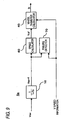
- Fig. 1 is a configuration diagram showing a configuration of a wheel diameter measuring apparatus of an electric vehicle in the first embodiment of the invention.
- an electric power converter 1 converts a DC voltage supplied from a pantograph 6 into an AC voltage, and supplies the voltage to a synchronous motor 2.
- the synchronous motor 2 shall be a permanent magnet synchronous motor for producing a magnetic field by a permanent magnet attached to a rotor, but is not limited to this.
- a wheel diameter measuring apparatus 3 is made of a voltage detector 4 for detecting an AC voltage of this electric power converter 1 and the synchronous motor 2, and a calculation part 5 for calculating a wheel diameter by the detected AC voltage.
- a wheel 7b is a drive wheel connected to the synchronous motor 2 through a gear and an axle (not shown), and a wheel 7a is a non-drive wheel which is not connected to the synchronous motor 2 directly, and is equipped with a speed detector 8 for detecting a speed of this non-drive wheel.
- This speed detector 8 may be a speed detector disposed in a security device or a brake device which is not connected to the synchronous motor 2, or a speed detector for measuring a vehicle speed for a speed meter of a cab in the front vehicle in the case of, for example, an electric vehicle.
- Respective connecting terminals 1u, 1v, 1w of a U phase, a V phase, a W phase of the AC side of the electric power converter 1 are connected to respective connecting terminals 2u, 2v, 2w of a U phase, a V phase, a W phase of the synchronous motor 2 by wiring 9 (made of 9u, 9v, 9w).
- the voltage detector 4 is connected to the U phase connecting terminal 1u and the V phase connecting terminal 1v of the AC side of the electric power converter, and detects a line voltage Vuv between U and V applied to the synchronous motor 2, but is not limited to this, and the voltage detector 4 could detect a line voltage applied to the synchronous motor 2.
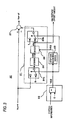
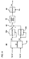
- Fig. 2 is a configuration diagram showing a configuration of the calculation part 5 in the first embodiment of the invention.
- the line voltage Vuv inputted from the voltage detector 4 is first inputted to a filter 10 and unnecessary noise obviously larger than the number of rotations of the synchronous motor 2 is eliminated and the line voltage Vuv becomes an output value Vuv-f.
- the output value Vuv-f is inputted to a speed calculator 30 as an output value Vuv-of after an influence of an offset voltage of the voltage detector 4 is further eliminated by an offset compensator 20.
- a rotational angle frequency ⁇ is calculated from Vuv-of and a calculation result is outputted to a wheel diameter calculator 40 as Vvf.
- a wheel diameter D is calculated by this Vvf and speed information V detected by the speed detector 8.
- a line voltage Vuv between U and V generated by production of a magnetic field by a permanent magnet attached to a rotor of the synchronous motor 2 is detected by the voltage detector 4.
- torque is generated in operation of the electric power converter 1, so that minute idling and sliding may occur in a drive wheel and the electric power converter 1 desirably be stopped in order to measure a wheel diameter with high accuracy.
- the line voltage Vuv between U and V detected by the voltage detector 4 is inputted to the filter 10 and unnecessary noise is eliminated.
- the filter 10 can be constructed of a first-order lag function as shown in Fig. 2 .
- a time constant T is set so that a frequency 10 times or more the maximum number of rotations of the synchronous motor 2 can be eliminated.
- the maximum number of rotations of the synchronous motor 2 is 300 Hz
- unnecessary noise can be eliminated when the time constant T of the filter 10 is set as shown in Formula (1).
- Fig. 3 is a configuration diagram showing a configuration of the offset compensator 20 in the first embodiment of the invention.
- the offset compensator 20 is made of a calculator 21, a stop deciding device 22 and a stop time measuring device 23, and makes a correction so that an output voltage becomes zero when an input voltage is zero.
- speed information V and an output value Vuv-f of the filter 10 are inputted and the synchronous motor does not rotate, an average offset amount ofav of the voltage detector 4 is computed and its average offset amount ofav is subtracted from Vuv-f and thereby, an influence of the offset amount can be eliminated. Consequently, an influence of an offset voltage of the voltage detector 4 can be eliminated and an accurate speed can be calculated.
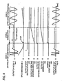
- Fig. 4 is an operation diagram showing an operation of the offset compensator 20 in the first embodiment of the invention.
- the operation of the offset compensator 20 will hereinafter be described using Figs. 3 and 4 .
- a voltage value Vuv-f inputted to the offset compensator 20 becomes imbalanced up and down by an influence of an offset of the voltage detector 4 as shown in Fig. 4 .
- a switching device 24a of Fig. 3 has a switch in the side of 0 (zero), and both outputs of an integrator 25 and a divider 26 become zero.
- the stop deciding device 22 sets an output value V22 at 0 and outputs the output value V22 to the switching devices 24a, 24b and the stop time measuring device 23.
- a switch of the switching device 24b is in the output side of the divider 26.
- Vuv-f is inputted through the switching device 24ato the integrator 25, to which an offset amount of the voltage detector 4 is inputted integrates its offset amount as shown in Fig. 4 .
- An output value V25 of this integrator 25 is inputted to the divider 26 and V25 is divided by an output value V23 of the stop time measuring device 23 inputted likewise and thereby, an average offset amount ofav within the stop time can be computed.
- the output value V22 of the stop deciding device 22 changes from 1 to 0 and the state proceeds to a state 3 shown in Fig. 4 .
- the switch returns to the 0 side in the switching device 24a and an input of the integrator 25 becomes zero and thereby, the output value V25 of the integrator 25 continues to hold the value before the input becomes zero.
- the output value V23 of the stop time measuring device 23 similarly continues to hold the value of the measured stop time. Consequently, when the electric vehicle does not stop, the average offset amount ofav becomes a constant value and in the switching device 24b, the switch returns from the 0 (zero) side to the side to which an output ofav of the divider 26 is inputted. Then, the average offset amount ofav is inputted to the switching device 24b and the average offset amount ofav is subtracted from a voltage value Vuv-f by a subtracter 27. Therefore, as shown in Fig.
- an influence of an offset amount of the voltage detector 4 can be eliminated and up and down imbalance in plus and minus is eliminated and thereby, a speed can be calculated accurately and a wheel diameter can be measured with high accuracy.
- FIG. 5 is a configuration diagram showing a configuration of the speed calculator 30 in the first embodiment of the invention. As shown in Fig. 5 , Vuv-of inputted to the speed calculator 30 is first differentiated two times by a two-time differentiator 31 and is divided by the original Vuv-of by a divider 32. Consequently, a speed [rad] of Vuv-of can be computed.
- the output value Vuv-of of the offset compensator 20 can be expressed as shown in Formula (2) when an amplitude is set at A and a rotational angle frequency of an AC voltage is set at ⁇ [rad].
- Formula (2) it is considered that an offset amount of the voltage detector 4 can be eliminated by the offset compensator 20 and the offset amount is set at zero.
- This divider 32 An output value of this divider 32 is inputted to a multiplier 33 and is multiplied by -1 and thereby, the value becomes a positive value and is inputted to a square root device 34. Then, the rotational angle frequency ⁇ of the AC voltage is computed easily by the square root device 34.
- the voltage value Vuv-of inputted to the speed calculator 30 is differentiated two times by the two-time differentiator 31, but it is an AC voltage, so that zero is present periodically and when the zero is differentiated, the value may become a large value infinitely or in a plus or minus direction.
- ⁇ computed by the square root device 34 is inputted to a filter 35 and a component of rotational angle frequency ⁇ of the stable AC voltage can be obtained and ⁇ is outputted as Vvf.
- T2 could be set at, for example, the minimum number or more of rotations measured. That is, when the number of rotations of 1 Hz or more wants to be measured, the number of rotations of 1 Hz or more can be measured stably by setting a value of Formula (6) as the time constant T2.
- the rotational angle frequency ⁇ of the AC voltage can be calculated easily from the output value Vuv-of of the offset compensator 20, so that the number of rotations of the synchronous motor 2 is found easily.
- An output value Vvf of this speed calculator 30 is next inputted to the wheel diameter calculator 40.
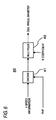
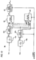
- Fig. 6 is a configuration diagram showing a configuration of the wheel diameter calculator 40 in the first embodiment of the invention.
- a wheel diameter D of the electric vehicle can be calculated from speed information V and the output value Vvf of the speed calculator 30.
- the wheel diameter D [m] can be computed by the following Formula (8).
- V WHEEL DIAMETER D GEAR RATIO GR x 3.6 POLAR LOGARITHM Pm xVvf
- the polar logarithm Pm is a constant of the synchronous motor 2 and the gear ratio GR indicates a ratio of a gear to the wheel 7b connected to the synchronous motor 2 through an axle and a gear.
- This gear ratio varies depending on setting of performance and a kind of the electric vehicle and the polar logarithm Pm also varies depending on performance and a kind of the synchronous motor 2, so that a coefficient K is defined as shown in Formula (9). Consequently, Formula (8) can be expressed as shown in Formula (10).
- the wheel diameter calculator 40 implements Formula (10) and as shown in Fig. 6 , the inputted speed information V is divided by Vvf by a divider 41 and is inputted to a multiplier 42 and is multiplied by the coefficient K previously prepared and the wheel diameter D can be calculated.
- This failure detector 50 is means for deciding that it is a failure of the voltage detector 4 when Vuv-of detected by the voltage detector 4 and offset-compensated, is smaller than the average offset amount ofav in the case where the synchronous motor 2 rotates and the speed information V is larger than a predetermined value.
- Fig. 7 is a configuration diagram showing a configuration of the failure detector 50 in the first embodiment of the invention
- Fig. 8 is an operation diagram showing an operation of the failure detector 50 in the first embodiment of the invention.
- An operation of the failure detector 50 will hereinafter be described using Figs. 7 and 8 .
- Vuv-of inputted to the failure detector 50 is first inputted to an absolute value device 51a
- Vuv-of is inputted to a filter 52.
- the filter 52 has a function of converting a value rectified by the absolute value device 51a into a DC voltage, so that a time constant T3 may be a sufficiently late value and could be set as shown by, for example, a value of Formula (11).
- An output value V52 of this filter 52 becomes a value of a DC voltage as shown in Fig. 8 . That is, here, an effective value of an AC voltage is obtained.
- a magnetic field is produced by a permanent magnet attached to a rotor and an AC voltage is generated and this AC voltage is detected by the voltage detector 4, so that the AC voltage can be detected when the synchronous motor 2 rotates. Therefore, it can be decided that it is in an abnormal state in which, for example, the voltage detector 4 fails when an effective value of an AC voltage value, in other words, the output value V52 of the filter 52 is zero or a small value in the case where the speed information V is larger than a predetermined speed.
- the speed information V inputted to the failure detector 50 is inputted to a greater-than comparator 54 and is compared with a predetermined speed V0.
- the predetermined speed V0 compared by the greater-than comparator 54 could be set at a value about 1/10 the maximum speed. For example, for an electric vehicle with the maximum speed of 300 km/h, the speed V0 is set at 30 km/h and when the speed information V exceeds 30 km/h, failure detection is performed.
- the wheel diameter measuring apparatus in an electric vehicle of speed sensorless vector control driven by a synchronous motor, can accurately measure a wheel diameter of the electric vehicle by detecting an AC voltage generated by a magnetic field of the synchronous motor. Also, there is an effect of obtaining the wheel diameter measuring apparatus of the electric vehicle with higher reliability by comprising a failure detector of a voltage detector.
- a wheel diameter D obtained by the wheel diameter measuring apparatus according to the first embodiment is supplied to a wheel diameter correction and thereby the correction according to a difference between the wheel diameters of each wheel can be made, so that the electric vehicle can be controlled accurately like the case of applying a conventional induction motor.
- a decision on replacement of a wheel may be made by measuring the extent of wear of the wheel using the wheel diameter D obtained by the wheel diameter measuring apparatus of the present application. Also, it may be used as management information about the electric vehicle by transmitting a measured value to a driving control system etc. of a station etc. and a communication network extended inside the electric vehicle of an integrated system, a vehicular train controller or a monitoring device of a cab, etc.
- a wheel diameter measuring apparatus 3 in a second embodiment is made of a voltage detector 4 for detecting an AC voltage of a synchronous motor 2 and an electric power converter 1, and a calculation part 5 (5a in the second embodiment) for calculating a wheel diameter by the detected AC voltage like the first embodiment, and differs from the first embodiment in that a speed calculator performs two-time differentiation two times (that is, four-time differentiation) in the calculation part 5a. Consequently, an influence of an offset of the voltage detector can be eliminated, so that it is configured so as not to require an offset compensator.
- the explanation is omitted by assigning the same numerals to the same portions as those of the first embodiment.
- Fig. 9 is a configuration diagram showing a configuration of the calculation part 5a in the second embodiment of the invention.
- a line voltage Vuv inputted from the voltage detector 4 is first inputted to a filter 10 and unnecessary noise obviously larger than the number of rotations of the synchronous motor 2 is eliminated and the line voltage Vuv becomes an output value Vuv-f. Then, the output value Vuv-f is inputted to a speed calculator 60.
- Fig. 10 is a configuration diagram showing a configuration of the speed calculator 60 in the second embodiment of the invention. An operation of this speed calculator 60 will hereinafter be described using Fig. 10 .
- Vuv-f inputted from the filter 10 can be expressed as shown in Formula (12) when an amplitude is set at A and a rotational angle frequency of an AC voltage is set at ⁇ [rad] and an offset amount is set at b.
- (Vuv-f)" in which (Vuv-f)' expressed by Formula (13) is further differentiated one time can be expressed as shown in Formula (14). That is, Formula (14) differentiates Vuv-f two times, and corresponds to an output value of a two-time differentiator 61a shown in Fig. 10 . Then, in this value, the offset amount is eliminated.
- the output value (Vuv-f)" of this two-time differentiator 61a is inputted to a two-time differentiator 61b and a divider 62, and is further differentiated two times in the two-time differentiator 61b, and becomes (Vuv-f)"" expressed by Formula (16).
- a square value of the rotational angle frequency ⁇ of an AC voltage can be calculated by dividing these output values as shown in Formula (17).
- the value becomes a positive value and is inputted to a square root device 64. Then, the rotational angle frequency ⁇ of the AC voltage can easily be computed by the square root device 64.
- Fig. 11 is a configuration diagram showing a configuration of the failure detector 70 in the second embodiment of the invention. An operation of this failure detector 70 will hereinafter be described using Fig. 11 .
- the failure detector 70 differs from the failure detector 50 of the first embodiment in that a value compared with an effective value of a voltage detection value Vuv-f by a less-than comparator 71 is only zero as shown in Fig. 11 .
- a filter 52 In the filter 52, like the first embodiment, a value rectified by the absolute value device 51c is converted into a DC voltage, so that a time constant T3 may be a sufficiently late value and could be set as shown by, for example, a value of Formula (11).
- An output value V52 of this filter 52 is an effective value of an AC voltage and is inputted to the less-than comparator 71.
- abnormal detection is performed when the effective value of the AC voltage becomes zero, but a comparison value of the less-than comparator 71 is not limited to this, and may be set at a predetermined value sufficiently smaller than a voltage generated by a magnetic field by a permanent magnet attached to a rotor at a predetermined speed V0 inputted to a greater-than comparator 54.
- the logical product (AND) device 55 to which V71 and V54 are respectively inputted from the less-than comparator 71 and the greater-than comparator 54 outputs Vuv-er which is an abnormal detection signal, and abnormality is detected.
- the wheel diameter measuring apparatus in an electric vehicle of speed sensorless vector control driven by a synchronous motor, can eliminate an influence of an offset amount of a voltage detector without using an offset compensator by having a speed calculator for performing calculation of two-time differentiation, and the wheel diameter measuring apparatus of the electric vehicle with higher reliability and a smaller number of components than the first embodiment can be obtained.
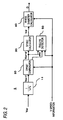
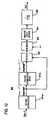
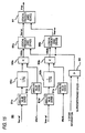
- Fig. 12 is a configuration diagram showing a configuration of a wheel diameter measuring apparatus in a third embodiment of the invention.
- the third embodiment differs from the first embodiment in that a wheel diameter measuring apparatus 3 comprises two voltage detectors 4a, 4b for detecting an AC voltage of a synchronous motor 2 and this electric power converter 1 and is made of a calculation part 5b for calculating a wheel diameter by the AC voltages detected from the two voltage detectors 4a, 4b.
- the explanation is omitted by assigning the same numerals to the same portions as those of the first embodiment.
- Fig. 13 is a configuration diagram showing a configuration of the calculation part 5b in the third embodiment of the invention.
- the line voltages are respectively outputted to offset compensators 20a, 20b as output values Vuv-f, Vvw-f.
- values Vuv-of, Vvw-of in which offset amounts of the voltage detectors 4a, 4b are eliminated are respectively calculated, and are outputted to a speed calculator 80 like the first embodiment.
- Fig. 14 is a configuration diagram showing a configuration of the speed calculator 80 in the third embodiment of the invention. An operation of this speed calculator 80 will hereinafter be described using Fig. 14 .
- Vuv-of, Vvw-of inputted to the speed calculator 80 are respectively converted into V ⁇ , V ⁇ expressed by Formula (18) by an ⁇ converter 81.
- Vvf indicating the number of rotations of the synchronous motor 2 can be calculated as shown in Formula (20) using Formula (19) .
- V ⁇ , V ⁇ outputted from the ⁇ converter 81 are respectively inputted to multipliers 82a, 82b and are squared
- V ⁇ , V ⁇ are inputted to an adder 83 and a square root device 84 and calculation of the right side of Formula (19) is performed.
- This result is inputted to a divider 85 and is divided by the magnetic flux ⁇ a of the permanent magnet previously prepared, and Formula (20) is calculated.
- Vvf indicating the number of rotations of the synchronous motor 2 can be obtained as an output of the divider 85.
- a wheel diameter D of the electric vehicle can be obtained like the first embodiment.
- a failure detector 90 to which the output values Vuv-of, Vvw-of, average offset amounts ofav1, ofav2 of the two offset compensators 20a, 20b and speed information V are inputted will be described in Fig. 13 .
- This failure detector 90 detects that the two voltage detectors 4a, 4b are abnormal, but a possibility that the two voltage detectors 4a, 4b fail simultaneously is low, so that the failure detector 90 detects both of abnormal detections Vuv-er and Vvw-er and detects that either the voltage detectors 4a, 4b or the synchronous motor 2 is abnormal.
- Fig. 15 is a configuration diagram showing a configuration of the failure detector 90 in the third embodiment of the invention. An operation of this failure detector 90 will hereinafter be described using Fig. 15 .
- Vuv-of inputted to the failure detector 90 is first inputted to an absolute value device 51a
- Vuv-of is inputted to a filter 52a.
- a value rectified by the absolute value device 51a is converted into a DC voltage, so that a time constant T3 may be a sufficiently late value and could be set as shown by, for example, a value of Formula (11).
- An output value of this filter 52a and a value in which an absolute value of an average offset amount ofav is taken by an absolute value device 51b are inputted to a less-than comparator 53a.
- a value compared by the less-than comparators 53a, 53b may be zero rather than the value in which the absolute value of the average offset amount ofav is taken.
- the speed information V inputted to the failure detector 90 is inputted to a greater-than comparator 54 and is compared with a predetermined speed V0.
- the predetermined speed V0 compared by the greater-than comparator 54 could be set at, for example, a value about 1/10 the maximum speed and for an electric vehicle with the maximum speed of 300 km/h, the speed V0 is set at 30 km/h and when the speed information V exceeds 30 km/h, failure detection is performed.
- the abnormal detection signals Vuv-er, Vvw-er are transmitted to, for example, a monitoring device of a cab other than the logical product (AND) device 91 and the monitoring device is notified of abnormality, or the abnormal detection signals Vuv-er, Vvw-er are inputted to a controller of the electric power converter 1 and an electric vehicle is stopped and a state of the synchronous motor 2 or the voltage detector 4 can be checked.
- the logical product (AND) device 91 detects that either the voltage detectors 4a, 4b or the synchronous motor 2 is abnormal, and outputs V-er. That is, by demagnetizing or detaching the permanent magnet attached to the rotor of the synchronous motor 2, a voltage is not generated even at high speed and this state is grasped from a situation in which the two voltage detectors are abnormal and it is detected as abnormality of the synchronous motor 2.
- the wheel diameter measuring apparatus in an electric vehicle of speed sensorless vector control driven by a synchronous motor, can calculate a wheel diameter of the electric vehicle by only simple calculation without performing complicated differential calculation processing in a calculation part by comprising two voltage detectors for detecting AC voltages of two places generated in the synchronous motor. Therefore, as compared with the first embodiment and the second embodiment described above, for example, the number of components of a circuit constructing the apparatus can be reduced greatly, so that the wheel diameter measuring apparatus with high reliability and a simple apparatus configuration can be obtained.
- failure detectors are had with respect to the respective voltage detectors, so that a failure can be detected individually and also abnormality of the synchronous motor itself can be detected by information from these two failure detectors and when abnormality occurs in the synchronous motor and the two voltage detectors, the abnormality can be respectively handled speedily and there is an effect capable of obtaining the wheel diameter measuring apparatus of the electric vehicle with higher reliability.
- the voltage detectors 4a, 4b shown in Fig. 12 are connected to a U phase connecting terminal lu and a V phase connecting terminal 1v and the V phase connecting terminal 1v and a W phase connecting terminal 1w of the AC side of the electric power converter, and detect a line voltage Vuv between U and V and a line voltage Vvw between V and W applied to the synchronous motor 2, but are not limited to this, and the voltage detector 4 could detect different two line voltages applied to the synchronous motor 2. Also, it goes without saying that it may be attached to a connecting terminal of the AC side of the synchronous motor 2.
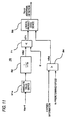
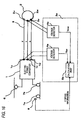
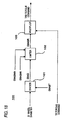
- Fig. 17 is a configuration diagram showing a configuration of a wheel diameter measuring apparatus in a fourth embodiment of the invention.
- a wheel diameter correcting part 100 is added and using a wheel diameter D calculated by a calculation part 5 of a wheel diameter measuring apparatus 3b, a torque command for controlling an electric power converter 1 can be corrected according to a wheel diameter difference.
- the explanation is omitted by assigning the same numerals to the same portions as those of the first embodiment.
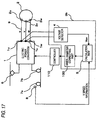
- Fig. 17 is a configuration diagram showing a configuration of the wheel diameter correcting part 100 in the fourth embodiment of the invention. An operation of this wheel diameter correcting part 100 will hereinafter be described using Fig. 18 .
- the wheel diameter correcting part 100 is constructed of a divider 101 for dividing a wheel diameter D by a reference wheel diameter DIAST and calculating a wheel diameter correction gain DIAG, a limiter 102 for setting the wheel diameter correction gain DIAG which is an output of the divider 101 so as not to become a minimum wheel diameter correction gain DIAGMI or less and a maximum wheel diameter correction gain DIAGMX or more, and a multiplier 103 for multiplying a wheel diameter correction gain DIAGR which is an output of the limiter 102 by a torque command TR as shown in Fig. 18 .
- the reference wheel diameter DIAST is normally set at 0.82 [m]. Also, the inventor et al. found that the wheel diameter D of an electric vehicle was within a range of 0.73m ⁇ D ⁇ 0.90m even on operating condition of any electric vehicle. Therefore, the wheel diameter gain DIAG which is an output calculated by the divider 101 is inputted to the limiter 102 and the following processing is performed.
- an output value DIAGR of the limiter 102 is set at the wheel diameter gain DIAG.
- the output value DIAGR of the limiter 102 is set at the minimum wheel diameter correction gain DIAGMI.
- the output value DIAGR of the limiter 102 is set at the maximum wheel diameter correction gain DIAGMX.
- the output value DIAGR of the limiter 102 and the torque command TR given from a cab etc. are inputted to the multiplier 103 and are multiplication is performed.
- the torque command TRD in consideration of the wheel diameter difference is generated and is outputted to the controller 110. That is, by inputting the torque command TRD according to an individual wheel diameter to the controller 110, the controller 110 can control the electric power converter 1 by, for example, publicly known vector control with wheel diameter correction.
- the wheel diameter measuring apparatus of the electric vehicle according to the fourth embodiment can correct a torque command for controlling an electric power converter according to a wheel diameter difference by inputting a wheel diameter D calculated by a calculation part to a wheel diameter correcting part since the wheel diameter correcting part is added in addition to the configuration of the first embodiment. That is, wheel diameter correction of the electric vehicle of speed sensorless vector control driven by the synchronous motor can be made, so that stable acceleration and deceleration control of the electric vehicle can be implemented and travel of the electric vehicle is made comfortable.
- the wheel diameter measuring apparatus 3 is based on the first embodiment, but is not limited to this, and it goes without saying that a similar effect can be obtained in the wheel diameter measuring apparatus of the second embodiment and the third embodiment.
Landscapes
- Engineering & Computer Science (AREA)
- Mechanical Engineering (AREA)
- Transportation (AREA)
- Power Engineering (AREA)
- Sustainable Development (AREA)
- Physics & Mathematics (AREA)
- General Physics & Mathematics (AREA)
- Life Sciences & Earth Sciences (AREA)
- Health & Medical Sciences (AREA)
- Sustainable Energy (AREA)
- General Health & Medical Sciences (AREA)
- Biomedical Technology (AREA)
- Electric Propulsion And Braking For Vehicles (AREA)
- Control Of Ac Motors In General (AREA)
- Measurement Of Length, Angles, Or The Like Using Electric Or Magnetic Means (AREA)
- Control Of Electric Motors In General (AREA)
Description
- This invention relates to a wheel diameter measuring apparatus of an electric vehicle, and particularly is a wheel diameter measuring apparatus of an electric vehicle used in an electric automobile, a railroad vehicle, etc. to which a synchronous motor is applied.
- The features of the preamble of
claim 1 are disclosed in documentCH-A-688728
In wheels of an electric vehicle, a minute diameter difference between each of the wheels occurs by wear during travel and in the case of assuming that torque of an electric motor is constant, acceleration of the wheel whose diameter has become small becomes large apparently. In order to stably control the electric vehicle in which acceleration and deceleration change apparently, estimating and correcting a wheel diameter from a rotational speed of each of the wheels has been implemented conventionally (for example, see Patent Reference 1). - On the other hand, from the standpoint of improvement in maintainability, reliability or miniaturization, a speed sensor for detecting a rotational speed of a driving shaft of an electric motor for driving an electric vehicle is not used in speed sensorless vector control applied to the electric vehicle in recent years. As a result, correcting a wheel diameter by estimating a rotational speed for a predetermined time while a torque current command increases or decreases has been proposed (for example, see Patent Reference 2).
-
- Patent Reference 1:
JP-A-60-210101 Fig. 1 ) - Patent Reference 2:
JP-A-2005-312126 Page 6,Fig. 1 ) - In the conventional wheel diameter measuring apparatus used in correction of a wheel diameter, it is premised on the case of applying an induction motor to an electric vehicle and particularly in speed sensorless vector control, a rotational speed of a driving shaft is estimated using a slip frequency peculiar to the induction motor, so that it could not be used as it is in an electric vehicle to which, for example, a synchronous motor is applied.
That is, in the electric vehicle of the speed sensorless vector control driven by the synchronous motor, a conventional wheel diameter estimation method could not be applied and there was a problem of being difficult to implement electric vehicle control similar to the case of applying the induction motor. - The invention has been implemented to solve the problem as described above, and an object of the invention is to provide a wheel diameter measuring apparatus capable of accurately measuring a wheel diameter of an electric vehicle capable of being supplied to a wheel diameter correction particularly in an electric vehicle of speed sensorless vector control to which a synchronous motor is applied.
- The invention is defined by the features of
claim 1. A wheel diameter measuring apparatus of an electric vehicle according to the invention is an apparatus for measuring a wheel diameter of an electric vehicle comprising a synchronous motor driven by an electric power converter for converting a DC voltage into an AC voltage, and comprises a voltage detector for detecting an AC voltage generated by a magnetic field of the synchronous motor during coasting of the electric vehicle in which the electric power converter stops, and a calculation part for calculating a wheel diameter of a wheel driven by the synchronous motor from an AC voltage detected by the voltage detector and speed information about the electric vehicle. Advantage of the Invention - According to a wheel diameter measuring apparatus of the invention, particularly in an electric vehicle of speed sensorless vector control to which a synchronous motor is applied, a wheel diameter can be measured accurately, so that stable control of the electric vehicle can be performed.
-
- [
Fig. 1] Fig. 1 is a configuration diagram of a wheel diameter measuring apparatus of an electric vehicle according to a first embodiment of the invention. - [
Fig. 2] Fig. 2 is a configuration diagram of a calculation part according to the first embodiment of the invention. - [
Fig. 3] Fig. 3 is a configuration diagram of an offset compensator according to the first embodiment of the invention. - [Fig. ]
Fig. 4 is an operation diagram showing an operation of the offset compensator according to the first embodiment of the invention. - [
Fig. 5] Fig. 5 is a configuration diagram of a speed calculator according to the first embodiment of the invention. - [
Fig. 6] Fig. 6 is a configuration diagram of a wheel diameter calculator according to the first embodiment of the invention. - [
Fig. 7] Fig. 7 is a configuration diagram of a failure detector according to the first embodiment of the invention. - [
Fig. 8] Fig. 8 is an operation diagram showing an operation of the failure detector according to the first embodiment of the invention. - [
Fig. 9] Fig. 9 is a configuration diagram of a calculation part of a wheel diameter measuring apparatus according to a second embodiment of the invention. - [
Fig. 10] Fig. 10 is a configuration diagram of a speed calculator according to the second embodiment of the invention. - [
Fig. 11] Fig. 11 is a configuration diagram of a failure detector according to the second embodiment of the invention. - [
Fig.12] Fig. 12 is a configuration diagram of a wheel diameter measuring apparatus of an electric vehicle according to a third embodiment of the invention. - [
Fig. 13] Fig. 13 is a configuration diagram of a calculation part according to the third embodiment of the invention. - [
Fig. 14] Fig. 14 is a configuration diagram of a speed calculator according to the third embodiment of the invention. - [
Fig. 15] Fig. 15 is a configuration diagram of a failure detector according to the third embodiment of the invention. - [
Fig. 16] Fig. 16 is another configuration diagram of the wheel diameter measuring apparatus of the electric vehicle according to the third embodiment of the invention. - [
Fig. 17] Fig. 17 is a configuration diagram of a wheel diameter measuring apparatus of an electric vehicle according to a fourth embodiment of the invention. - [
Fig. 18] Fig. 18 is a configuration diagram of a wheel diameter correcting part according to the fourth embodiment of the invention. -
- 1
- ELECTRIC POWER CONVERTER
- 1u,1v,1w
- CONNECTING TERMINAL
- 2
- SYNCHRONOUS MOTOR
- 2u,2v,2w
- CONNECTING TERMINAL
- 3,3a,3b
- WHEEL DIAMETER MEASURING APPARATUS
- 4,4a,4b,4c
- VOLTAGE DETECTOR
- 5,5a,5b
- CALCULATION PART
- 6
- PANTOGRAPH
- 7a,7b
- WHEEL
- 8
- SPEED DETECTOR
- 9,9u,9v,9w
- WIRING
- 10,10a,10b
- FILTER
- 20,20a,20b
- OFFSET COMPENSATOR
- 21
- OFFSET AMOUNT CALCULATOR
- 22
- STOP DECIDING DEVICE
- 23
- STOP TIME MEASURING DEVICE
- 24a,24b
- SWITCHING DEVICE
- 25
- INTEGRATOR
- 26
- DIVIDER
- 27
- SUBTRACTER
- 30
- SPEED CALCULATOR
- 31
- TWO-TIME DIFFERENTIATOR
- 32
- DIVIDER
- 33
- MULTIPLIER
- 34
- SQUARE ROOT DEVICE
- 35
- FILTER
- 40
- WHEEL DIAMETER CALCULATOR
- 41
- DIVIDER
- 42
- MULTIPLIER
- 50
- FAILURE DETECTOR
- 51a,51b,51c,51d,51e
- ABSOLUTE VALUE DEVICE
- 52,52a,52b
- FILTER
- 53,53a,53b
- LESS-THAN COMPARATOR
- 54
- GREATER-THAN COMPARATOR
- 55,55a,55b
- LOGICAL PRODUCT (AND) DEVICE
- 60
- SPEED CALCULATOR
- 61a,61b
- TWO-TIME DIFFERENTIATOR
- 62
- MULTIPLIER
- 63
- MULTIPLIER
- 64
- SQUARE ROOT DEVICE
- 65
- FILTER
- 70
- FAILURE DETECTOR
- 71
- LESS-THAN COMPARATOR
- 80
- SPEED CALCULATOR
- 81
- αβ CONVERTER
- 82a,82b
- MULTIPLIER
- 83
- ADDER
- 84
- SQUARE ROOT DEVICE
- 85
- DIVIDER
- 90
- FAILURE DETECTOR
- 91
- LOGICAL PRODUCT (AND) DEVICE
- 100
- WHEEL DIAMETER CORRECTING PART
- 101
- DIVIDER
- 102
- LIMITER
- 103
- MULTIPLIER
- 110
- CONTROLLER
- The invention will hereinafter be described in detail based on the drawings showing its embodiment.
-
Fig. 1 is a configuration diagram showing a configuration of a wheel diameter measuring apparatus of an electric vehicle in the first embodiment of the invention. InFig. 1 , anelectric power converter 1 converts a DC voltage supplied from apantograph 6 into an AC voltage, and supplies the voltage to asynchronous motor 2. In the present embodiment, thesynchronous motor 2 shall be a permanent magnet synchronous motor for producing a magnetic field by a permanent magnet attached to a rotor, but is not limited to this. A wheeldiameter measuring apparatus 3 is made of a voltage detector 4 for detecting an AC voltage of thiselectric power converter 1 and thesynchronous motor 2, and acalculation part 5 for calculating a wheel diameter by the detected AC voltage. - A
wheel 7b is a drive wheel connected to thesynchronous motor 2 through a gear and an axle (not shown), and awheel 7a is a non-drive wheel which is not connected to thesynchronous motor 2 directly, and is equipped with aspeed detector 8 for detecting a speed of this non-drive wheel. Thisspeed detector 8 may be a speed detector disposed in a security device or a brake device which is not connected to thesynchronous motor 2, or a speed detector for measuring a vehicle speed for a speed meter of a cab in the front vehicle in the case of, for example, an electric vehicle. - Respective connecting
terminals electric power converter 1 are connected to respective connectingterminals synchronous motor 2 by wiring 9 (made of 9u, 9v, 9w). Here, the voltage detector 4 is connected to the U phase connecting terminal 1u and the V phase connecting terminal 1v of the AC side of the electric power converter, and detects a line voltage Vuv between U and V applied to thesynchronous motor 2, but is not limited to this, and the voltage detector 4 could detect a line voltage applied to thesynchronous motor 2. -
Fig. 2 is a configuration diagram showing a configuration of thecalculation part 5 in the first embodiment of the invention. As shown inFig. 2 , in thecalculation part 5, the line voltage Vuv inputted from the voltage detector 4 is first inputted to afilter 10 and unnecessary noise obviously larger than the number of rotations of thesynchronous motor 2 is eliminated and the line voltage Vuv becomes an output value Vuv-f. The output value Vuv-f is inputted to aspeed calculator 30 as an output value Vuv-of after an influence of an offset voltage of the voltage detector 4 is further eliminated by an offsetcompensator 20. Then, in thespeed calculator 30, a rotational angle frequency ω is calculated from Vuv-of and a calculation result is outputted to awheel diameter calculator 40 as Vvf. In thewheel diameter calculator 40, a wheel diameter D is calculated by this Vvf and speed information V detected by thespeed detector 8. - Next, an operation of the wheel diameter measuring apparatus constructed as mentioned above will be described.
First, during coasting of an electric vehicle in which theelectric power converter 1 stops, a line voltage Vuv between U and V generated by production of a magnetic field by a permanent magnet attached to a rotor of thesynchronous motor 2 is detected by the voltage detector 4. For the electric vehicle, torque is generated in operation of theelectric power converter 1, so that minute idling and sliding may occur in a drive wheel and theelectric power converter 1 desirably be stopped in order to measure a wheel diameter with high accuracy.
The line voltage Vuv between U and V detected by the voltage detector 4 is inputted to thefilter 10 and unnecessary noise is eliminated. Here, thefilter 10 can be constructed of a first-order lag function as shown inFig. 2 . In this case, a time constant T is set so that afrequency 10 times or more the maximum number of rotations of thesynchronous motor 2 can be eliminated. For example, when the maximum number of rotations of thesynchronous motor 2 is 300 Hz, unnecessary noise can be eliminated when the time constant T of thefilter 10 is set as shown in Formula (1). -

-
Fig. 3 is a configuration diagram showing a configuration of the offsetcompensator 20 in the first embodiment of the invention. As shown inFig. 3 , the offsetcompensator 20 is made of acalculator 21, astop deciding device 22 and a stoptime measuring device 23, and makes a correction so that an output voltage becomes zero when an input voltage is zero. When speed information V and an output value Vuv-f of thefilter 10 are inputted and the synchronous motor does not rotate, an average offset amount ofav of the voltage detector 4 is computed and its average offset amount ofav is subtracted from Vuv-f and thereby, an influence of the offset amount can be eliminated. Consequently, an influence of an offset voltage of the voltage detector 4 can be eliminated and an accurate speed can be calculated. -
Fig. 4 is an operation diagram showing an operation of the offsetcompensator 20 in the first embodiment of the invention. The operation of the offsetcompensator 20 will hereinafter be described usingFigs. 3 and4 .
First, in astate 1 before making offset compensation, a voltage value Vuv-f inputted to the offsetcompensator 20 becomes imbalanced up and down by an influence of an offset of the voltage detector 4 as shown inFig. 4 . In this state, aswitching device 24a ofFig. 3 has a switch in the side of 0 (zero), and both outputs of anintegrator 25 and adivider 26 become zero. When speed information V is not zero, thestop deciding device 22 sets an output value V22 at 0 and outputs the output value V22 to theswitching devices time measuring device 23. In addition, in thestate 1, a switch of theswitching device 24b is in the output side of thedivider 26. - Next, the
electric power converter 1 stops and the speed information V decreases gradually and in the case of becoming astate 2 in which the speed information V becomes zero, the speed information V=0 is inputted to the stop decidingdevice 22 and the output value V22=1 is outputted. Then, in theswitching device 24a to which this output value V22 is inputted, the switch is switched from the 0 (zero) side to the side to which Vuv-f is inputted and on the other hand, the switch is switched to the 0 (zero) side in theswitching device 24b. - The stop
time measuring device 23 measures time for which the synchronous motor stops by inputting V22=1. As one example of means for measuring the stop time, an input value to the stoptime measuring device 23 is 1, so that an output becomes 1 when integration is performed for one second by simply performing integration by an integrator. That is, when V22=1 is inputted, an output of integration matches with integration time (stop time of the synchronous motor) and the stop time can be measured. - On the other hand, Vuv-f is inputted through the switching device 24ato the
integrator 25, to which an offset amount of the voltage detector 4 is inputted integrates its offset amount as shown inFig. 4 . An output value V25 of thisintegrator 25 is inputted to thedivider 26 and V25 is divided by an output value V23 of the stoptime measuring device 23 inputted likewise and thereby, an average offset amount ofav within the stop time can be computed. - Further, when the
synchronous motor 2 rotates or the electric vehicle accelerates and the speed information V does not become zero, the output value V22 of thestop deciding device 22 changes from 1 to 0 and the state proceeds to astate 3 shown inFig. 4 . In the case of proceeding to thestate 3, as shown inFig. 4 , the switch returns to the 0 side in theswitching device 24a and an input of theintegrator 25 becomes zero and thereby, the output value V25 of theintegrator 25 continues to hold the value before the input becomes zero. - Also, the output value V23 of the stop
time measuring device 23 similarly continues to hold the value of the measured stop time. Consequently, when the electric vehicle does not stop, the average offset amount ofav becomes a constant value and in theswitching device 24b, the switch returns from the 0 (zero) side to the side to which an output ofav of thedivider 26 is inputted. Then, the average offset amount ofav is inputted to theswitching device 24b and the average offset amount ofav is subtracted from a voltage value Vuv-f by asubtracter 27. Therefore, as shown inFig. 4 , in an output voltage value Vuv-of of the offsetcompensator 20, an influence of an offset amount of the voltage detector 4 can be eliminated and up and down imbalance in plus and minus is eliminated and thereby, a speed can be calculated accurately and a wheel diameter can be measured with high accuracy. - Then, this Vuv-of is inputted to the
speed calculator 30 and afailure detector 50.Fig. 5 is a configuration diagram showing a configuration of thespeed calculator 30 in the first embodiment of the invention. As shown inFig. 5 , Vuv-of inputted to thespeed calculator 30 is first differentiated two times by a two-time differentiator 31 and is divided by the original Vuv-of by adivider 32. Consequently, a speed [rad] of Vuv-of can be computed. - The principle will hereinafter be described using a formula.
The output value Vuv-of of the offsetcompensator 20 can be expressed as shown in Formula (2) when an amplitude is set at A and a rotational angle frequency of an AC voltage is set at ω [rad]. In addition, in Formula (2), it is considered that an offset amount of the voltage detector 4 can be eliminated by the offsetcompensator 20 and the offset amount is set at zero. -

- (Vuv-of)' in which Vuv-of expressed by Formula (2) is differentiated one time can be expressed as shown in Formula (3).
-

- Then, (Vuv-of) " in which (Vuv-of)' expressed by Formula (3) is further differentiated one time, that is, an output value of the two-
time differentiator 31 can be expressed as shown in Formula (4). -

- In the
divider 32, use of Formula (2) and Formula (4) shows Formula (5) and a square value of the rotational angle frequency ω of the AC voltage can be computed. -

- An output value of this
divider 32 is inputted to amultiplier 33 and is multiplied by -1 and thereby, the value becomes a positive value and is inputted to asquare root device 34. Then, the rotational angle frequency ω of the AC voltage is computed easily by thesquare root device 34. - Here, the voltage value Vuv-of inputted to the
speed calculator 30 is differentiated two times by the two-time differentiator 31, but it is an AC voltage, so that zero is present periodically and when the zero is differentiated, the value may become a large value infinitely or in a plus or minus direction. In order to eliminate that, ω computed by thesquare root device 34 is inputted to afilter 35 and a component of rotational angle frequency ω of the stable AC voltage can be obtained and ω is outputted as Vvf. - In addition, when a time constant of the
filter 35 is set at T2, T2 could be set at, for example, the minimum number or more of rotations measured. That is, when the number of rotations of 1 Hz or more wants to be measured, the number of rotations of 1 Hz or more can be measured stably by setting a value of Formula (6) as the time constant T2. -

- As described above, in the
speed calculator 30, the rotational angle frequency ω of the AC voltage can be calculated easily from the output value Vuv-of of the offsetcompensator 20, so that the number of rotations of thesynchronous motor 2 is found easily. An output value Vvf of thisspeed calculator 30 is next inputted to thewheel diameter calculator 40. -
Fig. 6 is a configuration diagram showing a configuration of thewheel diameter calculator 40 in the first embodiment of the invention. As shown inFig. 6 , in thewheel diameter calculator 40, a wheel diameter D of the electric vehicle can be calculated from speed information V and the output value Vvf of thespeed calculator 30.
Now, when a unit of the speed information V shall be km/h, the following relation between the speed information V and Vvf [rad] indicating the number of rotations of thesynchronous motor 2 holds generally and the wheel diameter D [m] can be computed by the following Formula (8). -

-

- In addition, the polar logarithm Pm is a constant of the
synchronous motor 2 and the gear ratio GR indicates a ratio of a gear to thewheel 7b connected to thesynchronous motor 2 through an axle and a gear. This gear ratio varies depending on setting of performance and a kind of the electric vehicle and the polar logarithm Pm also varies depending on performance and a kind of thesynchronous motor 2, so that a coefficient K is defined as shown in Formula (9).
Consequently, Formula (8) can be expressed as shown in Formula (10). -

-

- Here, the
wheel diameter calculator 40 implements Formula (10) and as shown inFig. 6 , the inputted speed information V is divided by Vvf by adivider 41 and is inputted to amultiplier 42 and is multiplied by the coefficient K previously prepared and the wheel diameter D can be calculated. - On the other hand, the
failure detector 50 to which the speed information V, the average offset amount ofav and the output value Vuv-of of the offsetcompensator 20 are inputted will be described inFig. 2 . Thisfailure detector 50 is means for deciding that it is a failure of the voltage detector 4 when Vuv-of detected by the voltage detector 4 and offset-compensated, is smaller than the average offset amount ofav in the case where thesynchronous motor 2 rotates and the speed information V is larger than a predetermined value. -
Fig. 7 is a configuration diagram showing a configuration of thefailure detector 50 in the first embodiment of the invention, andFig. 8 is an operation diagram showing an operation of thefailure detector 50 in the first embodiment of the invention. An operation of thefailure detector 50 will hereinafter be described usingFigs. 7 and8 .
As shown inFig. 7 , after Vuv-of inputted to thefailure detector 50 is first inputted to anabsolute value device 51a, Vuv-of is inputted to afilter 52. Thefilter 52 has a function of converting a value rectified by theabsolute value device 51a into a DC voltage, so that a time constant T3 may be a sufficiently late value and could be set as shown by, for example, a value of Formula (11). -

- An output value V52 of this
filter 52 becomes a value of a DC voltage as shown inFig. 8 . That is, here, an effective value of an AC voltage is obtained. When thesynchronous motor 2 rotates, a magnetic field is produced by a permanent magnet attached to a rotor and an AC voltage is generated and this AC voltage is detected by the voltage detector 4, so that the AC voltage can be detected when thesynchronous motor 2 rotates.
Therefore, it can be decided that it is in an abnormal state in which, for example, the voltage detector 4 fails when an effective value of an AC voltage value, in other words, the output value V52 of thefilter 52 is zero or a small value in the case where the speed information V is larger than a predetermined speed. - As a result of that, the output value V52 of the
filter 52 and a value in which an absolute value of the average offset amount ofav is taken by anabsolute value device 51b are inputted to a less-thancomparator 53 and the less-thancomparator 53 compares these values and when the output value V52 of thefilter 52 is smaller than an output value of theabsolute value device 51b, an output value V53=1 is outputted to a logical product (AND)device 55 and when the output value V52 is larger than or equal to the output value in reverse, the output value V53=0 is outputted to the logical product (AND)device 55. - On the other hand, the speed information V inputted to the
failure detector 50 is inputted to a greater-thancomparator 54 and is compared with a predetermined speed V0. The greater-thancomparator 54 outputs an output value V54=1 to the logical product (AND)device 55 when the speed information V is larger than the predetermined speed V0, and outputs the output value V54=0 to the logical product (AND)device 55 when the speed information V is smaller than or equal to the predetermined speed V0 in reverse. In addition, the predetermined speed V0 compared by the greater-thancomparator 54 could be set at a value about 1/10 the maximum speed. For example, for an electric vehicle with the maximum speed of 300 km/h, the speed V0 is set at 30 km/h and when the speed information V exceeds 30 km/h, failure detection is performed. - The logical product (AND)
device 55 to which V53 and V54 are respectively inputted from the less-thancomparator 53 and the greater-thancomparator 54 outputs Vuv-er which is an abnormal detection signal when V53=1 and V54=1 are satisfied. It may be constructed so that this abnormal detection signal Vuv-er is transmitted to, for example, a monitoring device of a cab and the monitoring device is notified of abnormality, or the abnormal detection signal Vuv-er is inputted to a controller of theelectric power converter 1 and an electric vehicle is stopped and a state of thesynchronous motor 2 or the voltage detector 4 can be checked. - As described above, in an electric vehicle of speed sensorless vector control driven by a synchronous motor, the wheel diameter measuring apparatus according to the first embodiment can accurately measure a wheel diameter of the electric vehicle by detecting an AC voltage generated by a magnetic field of the synchronous motor. Also, there is an effect of obtaining the wheel diameter measuring apparatus of the electric vehicle with higher reliability by comprising a failure detector of a voltage detector.
- Further, a wheel diameter D obtained by the wheel diameter measuring apparatus according to the first embodiment is supplied to a wheel diameter correction and thereby the correction according to a difference between the wheel diameters of each wheel can be made, so that the electric vehicle can be controlled accurately like the case of applying a conventional induction motor. Also, a decision on replacement of a wheel may be made by measuring the extent of wear of the wheel using the wheel diameter D obtained by the wheel diameter measuring apparatus of the present application. Also, it may be used as management information about the electric vehicle by transmitting a measured value to a driving control system etc. of a station etc. and a communication network extended inside the electric vehicle of an integrated system, a vehicular train controller or a monitoring device of a cab, etc.
- A wheel
diameter measuring apparatus 3 in a second embodiment is made of a voltage detector 4 for detecting an AC voltage of asynchronous motor 2 and anelectric power converter 1, and a calculation part 5 (5a in the second embodiment) for calculating a wheel diameter by the detected AC voltage like the first embodiment, and differs from the first embodiment in that a speed calculator performs two-time differentiation two times (that is, four-time differentiation) in thecalculation part 5a. Consequently, an influence of an offset of the voltage detector can be eliminated, so that it is configured so as not to require an offset compensator.
In addition, the explanation is omitted by assigning the same numerals to the same portions as those of the first embodiment. -
Fig. 9 is a configuration diagram showing a configuration of thecalculation part 5a in the second embodiment of the invention. In thecalculation part 5a of the second embodiment, a line voltage Vuv inputted from the voltage detector 4 is first inputted to afilter 10 and unnecessary noise obviously larger than the number of rotations of thesynchronous motor 2 is eliminated and the line voltage Vuv becomes an output value Vuv-f. Then, the output value Vuv-f is inputted to aspeed calculator 60. -
Fig. 10 is a configuration diagram showing a configuration of thespeed calculator 60 in the second embodiment of the invention. An operation of thisspeed calculator 60 will hereinafter be described usingFig. 10 .
First, Vuv-f inputted from thefilter 10 can be expressed as shown in Formula (12) when an amplitude is set at A and a rotational angle frequency of an AC voltage is set at ω [rad] and an offset amount is set at b. -

- Here, the inventor et al. found that the offset amount b was eliminated as shown in the following Formula (13) in (Vuv-f)' in which Vuv-f expressed by Formula (12) is differentiated one time.
-

- (Vuv-f)" in which (Vuv-f)' expressed by Formula (13) is further differentiated one time can be expressed as shown in Formula (14). That is, Formula (14) differentiates Vuv-f two times, and corresponds to an output value of a two-time differentiator 61a shown in
Fig. 10 . Then, in this value, the offset amount is eliminated. -

- The output value (Vuv-f)" of this two-time differentiator 61a is inputted to a two-
time differentiator 61b and adivider 62, and is further differentiated two times in the two-time differentiator 61b, and becomes (Vuv-f)"" expressed by Formula (16). -

-

- In the
divider 62 to which the output value (Vuv-f)" of the two-time differentiator 61a and the output value (Vuv-f)"" of the two-time differentiator 61b are inputted, a square value of the rotational angle frequency ω of an AC voltage can be calculated by dividing these output values as shown in Formula (17). -

- Afterward, like the first embodiment, by being inputted to a
multiplier 63 and being multiplied by -1, the value becomes a positive value and is inputted to asquare root device 64. Then, the rotational angle frequency ω of the AC voltage can easily be computed by thesquare root device 64. - Next, a
failure detector 70 to which speed information V and the output value Vuv-f of thefilter 10 are inputted will be described inFig. 9 .
Fig. 11 is a configuration diagram showing a configuration of thefailure detector 70 in the second embodiment of the invention. An operation of thisfailure detector 70 will hereinafter be described usingFig. 11 .
Thefailure detector 70 differs from thefailure detector 50 of the first embodiment in that a value compared with an effective value of a voltage detection value Vuv-f by a less-thancomparator 71 is only zero as shown inFig. 11 . - In
Fig. 11 , after the output value Vuv-f of thefilter 10 inputted to thefailure detector 70 is first inputted to anabsolute value device 51c, Vuv-f is inputted to afilter 52. In thefilter 52, like the first embodiment, a value rectified by theabsolute value device 51c is converted into a DC voltage, so that a time constant T3 may be a sufficiently late value and could be set as shown by, for example, a value of Formula (11). - An output value V52 of this
filter 52 is an effective value of an AC voltage and is inputted to the less-thancomparator 71. In the less-thancomparator 71, when the output value V52 of thefilter 52 is smaller than zero, an output value V71=1 is outputted to a logical product (AND)device 55 and when the output value V52 is larger than or equal to zero in reverse, the output value V71=0 is outputted to the logical product (AND)device 55. Therefore, here, abnormal detection is performed when the effective value of the AC voltage becomes zero, but a comparison value of the less-thancomparator 71 is not limited to this, and may be set at a predetermined value sufficiently smaller than a voltage generated by a magnetic field by a permanent magnet attached to a rotor at a predetermined speed V0 inputted to a greater-thancomparator 54. - Like the first embodiment, when V71=1 and V54=1 are satisfied, the logical product (AND)
device 55 to which V71 and V54 are respectively inputted from the less-thancomparator 71 and the greater-thancomparator 54 outputs Vuv-er which is an abnormal detection signal, and abnormality is detected. - As described above, in an electric vehicle of speed sensorless vector control driven by a synchronous motor, the wheel diameter measuring apparatus according to the second embodiment can eliminate an influence of an offset amount of a voltage detector without using an offset compensator by having a speed calculator for performing calculation of two-time differentiation, and the wheel diameter measuring apparatus of the electric vehicle with higher reliability and a smaller number of components than the first embodiment can be obtained.
-
Fig. 12 is a configuration diagram showing a configuration of a wheel diameter measuring apparatus in a third embodiment of the invention. The third embodiment differs from the first embodiment in that a wheeldiameter measuring apparatus 3 comprises twovoltage detectors synchronous motor 2 and thiselectric power converter 1 and is made of acalculation part 5b for calculating a wheel diameter by the AC voltages detected from the twovoltage detectors
In addition, the explanation is omitted by assigning the same numerals to the same portions as those of the first embodiment. - As shown in
Fig. 12 , first, during coasting of an electric vehicle in which theelectric power converter 1 stops, line voltages Vuv, Vvw between U and V and between V and W generated by production of a magnetic field by a permanent magnet attached to a rotor of thesynchronous motor 2 are detected by thevoltage detectors calculation part 5b. -
Fig. 13 is a configuration diagram showing a configuration of thecalculation part 5b in the third embodiment of the invention. As shown inFig. 13 , after the inputted line voltages Vuv, Vvw are respectively inputted tofilters compensators compensators voltage detectors speed calculator 80 like the first embodiment. -
Fig. 14 is a configuration diagram showing a configuration of thespeed calculator 80 in the third embodiment of the invention. An operation of thisspeed calculator 80 will hereinafter be described usingFig. 14 .
First, Vuv-of, Vvw-of inputted to thespeed calculator 80 are respectively converted into Vα, Vβ expressed by Formula (18) by anαβ converter 81. -

- Here, when a magnetic flux of the permanent magnet attached to the rotor of the
synchronous motor 2 is set at Φa and the number of rotations of thesynchronous motor 2 is set at Vvf, Vα, Vβ of Formula (18) can be expressed as shown in the following Formula (19). -

- Since the magnetic flux Φa of the permanent magnet attached to the rotor of the
synchronous motor 2 can be grasped previously, Vvf indicating the number of rotations of thesynchronous motor 2 can be calculated as shown in Formula (20) using Formula (19) . -

- As shown in
Fig. 14 , after Vα, Vβ outputted from theαβ converter 81 are respectively inputted tomultipliers adder 83 and asquare root device 84 and calculation of the right side of Formula (19) is performed. This result is inputted to adivider 85 and is divided by the magnetic flux Φa of the permanent magnet previously prepared, and Formula (20) is calculated. As a result of this, Vvf indicating the number of rotations of thesynchronous motor 2 can be obtained as an output of thedivider 85. - After Vvf calculated by the
speed calculator 80 as described above is inputted to awheel diameter calculator 40 as shown inFig. 13 , a wheel diameter D of the electric vehicle can be obtained like the first embodiment. - On the other hand, a
failure detector 90 to which the output values Vuv-of, Vvw-of, average offset amounts ofav1, ofav2 of the two offsetcompensators Fig. 13 . Thisfailure detector 90 detects that the twovoltage detectors voltage detectors failure detector 90 detects both of abnormal detections Vuv-er and Vvw-er and detects that either thevoltage detectors synchronous motor 2 is abnormal. -
Fig. 15 is a configuration diagram showing a configuration of thefailure detector 90 in the third embodiment of the invention. An operation of thisfailure detector 90 will hereinafter be described usingFig. 15 .
After Vuv-of inputted to thefailure detector 90 is first inputted to anabsolute value device 51a, Vuv-of is inputted to afilter 52a. In thefilter 52a, like the first embodiment, a value rectified by theabsolute value device 51a is converted into a DC voltage, so that a time constant T3 may be a sufficiently late value and could be set as shown by, for example, a value of Formula (11). - An output value of this
filter 52a and a value in which an absolute value of an average offset amount ofav is taken by anabsolute value device 51b are inputted to a less-thancomparator 53a. The less-thancomparator 53a compares these values and when the output value of thefilter 52a is smaller than an output value of theabsolute value device 51b, an output value V53a=1 is outputted to a logical product (AND)device 55a and when the output value is larger than or equal to the output value in reverse, the output value V53a=O is outputted to the logical product (AND)device 55a. - Similarly, Vvw-of between V and W is calculated and an output value V53b=1 or V53b=0 is outputted from a less-than
comparator 53b to a logical product (AND)device 55b. In addition, like the second embodiment, a value compared by the less-thancomparators - On the other hand, the speed information V inputted to the
failure detector 90 is inputted to a greater-thancomparator 54 and is compared with a predetermined speed V0. The greater-thancomparator 54 outputs an output value V54=1 to the logical product (AND)devices devices comparator 54 could be set at, for example, a value about 1/10 the maximum speed and for an electric vehicle with the maximum speed of 300 km/h, the speed V0 is set at 30 km/h and when the speed information V exceeds 30 km/h, failure detection is performed. - Like the case of the first embodiment, the logical product (AND)
devices device 91, and output Vvw-er when V53b=1 and V54=1 are satisfied to the logical product (AND)device 91. In addition, it may be constructed so that the abnormal detection signals Vuv-er, Vvw-er are transmitted to, for example, a monitoring device of a cab other than the logical product (AND)device 91 and the monitoring device is notified of abnormality, or the abnormal detection signals Vuv-er, Vvw-er are inputted to a controller of theelectric power converter 1 and an electric vehicle is stopped and a state of thesynchronous motor 2 or the voltage detector 4 can be checked. - Also, when both of Vuv-er and Vvw-er are inputted, the logical product (AND)
device 91 detects that either thevoltage detectors synchronous motor 2 is abnormal, and outputs V-er. That is, by demagnetizing or detaching the permanent magnet attached to the rotor of thesynchronous motor 2, a voltage is not generated even at high speed and this state is grasped from a situation in which the two voltage detectors are abnormal and it is detected as abnormality of thesynchronous motor 2. - As described above, in an electric vehicle of speed sensorless vector control driven by a synchronous motor, the wheel diameter measuring apparatus according to the third embodiment can calculate a wheel diameter of the electric vehicle by only simple calculation without performing complicated differential calculation processing in a calculation part by comprising two voltage detectors for detecting AC voltages of two places generated in the synchronous motor. Therefore, as compared with the first embodiment and the second embodiment described above, for example, the number of components of a circuit constructing the apparatus can be reduced greatly, so that the wheel diameter measuring apparatus with high reliability and a simple apparatus configuration can be obtained.
- Further, failure detectors are had with respect to the respective voltage detectors, so that a failure can be detected individually and also abnormality of the synchronous motor itself can be detected by information from these two failure detectors and when abnormality occurs in the synchronous motor and the two voltage detectors, the abnormality can be respectively handled speedily and there is an effect capable of obtaining the wheel diameter measuring apparatus of the electric vehicle with higher reliability.
- In addition, the
voltage detectors Fig. 12 are connected to a U phase connecting terminal lu and a V phase connecting terminal 1v and the V phase connecting terminal 1v and a W phase connecting terminal 1w of the AC side of the electric power converter, and detect a line voltage Vuv between U and V and a line voltage Vvw between V and W applied to thesynchronous motor 2, but are not limited to this, and the voltage detector 4 could detect different two line voltages applied to thesynchronous motor 2. Also, it goes without saying that it may be attached to a connecting terminal of the AC side of thesynchronous motor 2. - Therefore, for example, as shown in
Fig. 16 , when thevoltage detector 4a is disposed in a terminal of the side of theelectric power converter 1 and thevoltage detector 4c is disposed in a terminal of the side of thesynchronous motor 2, it becomes unnecessary to attach two voltage detectors to one phase connecting terminal as described in the voltage detectors shown inFig. 12 and there is an effect capable of improving efficiency of attachment work. -
Fig. 17 is a configuration diagram showing a configuration of a wheel diameter measuring apparatus in a fourth embodiment of the invention. In addition to the configuration of the first embodiment, in the fourth embodiment, a wheeldiameter correcting part 100 is added and using a wheel diameter D calculated by acalculation part 5 of a wheeldiameter measuring apparatus 3b, a torque command for controlling anelectric power converter 1 can be corrected according to a wheel diameter difference.
In addition, the explanation is omitted by assigning the same numerals to the same portions as those of the first embodiment. - As shown in
Fig. 17 , in the wheeldiameter measuring apparatus 3b of an electric vehicle according to the fourth embodiment, the wheel diameter D calculated by thecalculation part 5 is inputted to the wheeldiameter correcting part 100 and a torque command TRD in consideration of a wheel diameter difference is generated and is inputted to acontroller 110 for controlling theelectric power converter 1.
Fig. 18 is a configuration diagram showing a configuration of the wheeldiameter correcting part 100 in the fourth embodiment of the invention. An operation of this wheeldiameter correcting part 100 will hereinafter be described usingFig. 18 . - The wheel
diameter correcting part 100 is constructed of adivider 101 for dividing a wheel diameter D by a reference wheel diameter DIAST and calculating a wheel diameter correction gain DIAG, alimiter 102 for setting the wheel diameter correction gain DIAG which is an output of thedivider 101 so as not to become a minimum wheel diameter correction gain DIAGMI or less and a maximum wheel diameter correction gain DIAGMX or more, and amultiplier 103 for multiplying a wheel diameter correction gain DIAGR which is an output of thelimiter 102 by a torque command TR as shown inFig. 18 . - In the
divider 101, calculation of the following Formula (21) is performed. -

- In addition, the reference wheel diameter DIAST is normally set at 0.82 [m]. Also, the inventor et al. found that the wheel diameter D of an electric vehicle was within a range of 0.73m≤D≤0.90m even on operating condition of any electric vehicle. Therefore, the wheel diameter gain DIAG which is an output calculated by the
divider 101 is inputted to thelimiter 102 and the following processing is performed. - In the case of minimum wheel diameter correction gain DIAGMI≤wheel diameter gain DIAG≤maximum wheel diameter correction gain DIAGMX, an output value DIAGR of the
limiter 102 is set at the wheel diameter gain DIAG.
In the case of minimum wheel diameter correction gain DIAGMI>wheel diameter gain DIAG, the output value DIAGR of thelimiter 102 is set at the minimum wheel diameter correction gain DIAGMI.
In the case of wheel diameter gain DIAG>maximum wheel diameter correction gain DIAGMX, the output value DIAGR of thelimiter 102 is set at the maximum wheel diameter correction gain DIAGMX. - Here, the maximum wheel diameter correction gain DIAGMX could be set at, for example, a value of 1 or more and 1.1 (=0.90/0.82) or less since the wheel diameter D is within the range of 0.73m≤wheel diameter D≤0. 90m and similarly, the minimum wheel diameter correction gain DIAGMI could be set at, for example, a value of 0.9 (=0.73/0.82) or more and 1 or less since the wheel diameter D is within the range of 0.73m≤wheel diameter D≤0.90m.
By thislimiter 102, correction is not made by a gain incapable of assumption and reliability of torque command control can be enhanced. - The output value DIAGR of the
limiter 102 and the torque command TR given from a cab etc. are inputted to themultiplier 103 and are multiplication is performed. As a result of that, the torque command TRD in consideration of the wheel diameter difference is generated and is outputted to thecontroller 110. That is, by inputting the torque command TRD according to an individual wheel diameter to thecontroller 110, thecontroller 110 can control theelectric power converter 1 by, for example, publicly known vector control with wheel diameter correction. - As described above, in an electric vehicle of speed sensorless vector control driven by a synchronous motor, the wheel diameter measuring apparatus of the electric vehicle according to the fourth embodiment can correct a torque command for controlling an electric power converter according to a wheel diameter difference by inputting a wheel diameter D calculated by a calculation part to a wheel diameter correcting part since the wheel diameter correcting part is added in addition to the configuration of the first embodiment. That is, wheel diameter correction of the electric vehicle of speed sensorless vector control driven by the synchronous motor can be made, so that stable acceleration and deceleration control of the electric vehicle can be implemented and travel of the electric vehicle is made comfortable.
- In addition, in the explanation of the fourth embodiment described above, the wheel
diameter measuring apparatus 3 is based on the first embodiment, but is not limited to this, and it goes without saying that a similar effect can be obtained in the wheel diameter measuring apparatus of the second embodiment and the third embodiment.
Claims (14)
- A wheel diameter (3, 3a, 3b) measuring apparatus of an electric vehicle comprising a synchronous motor (2) driven by an electric power converter (1) for converting a DC voltage into an AC voltage, characterized by comprising:a voltage detector (4, 4a, 4b) for detecting an AC voltage generated by a magnetic field of the synchronous motor (2) during coasting of the electric vehicle in which the electric power converter (1) stops, anda calculation part (5, 5a, 5b) for calculating a wheel diameter (7a, 7b) of a wheel driven by the synchronous motor (2) from an AC voltage detected by the voltage detector (4, 4; 4b) and speed information about the electric vehicle.
- A wheel diameter measuring apparatus of an electric vehicle as claimed in claim 1, characterized in that the calculation part comprises a speed detector (8) for detecting a speed of a non-driving wheel which is not driven directly by the synchronous motor (2), and a failure detector (50) for comparing a predetermined value with the detection value of the speed detector (8) and detecting a failure of the voltage detector (4, 4a, 4b).
- A wheel diameter measuring apparatus of an electric vehicle as claimed in claim 1, characterized in that the calculation part (5, 5a, 5b) comprises a speed calculator (60, 80) for computing a rotational angle frequency and eliminates an offset voltage from an AC voltage detected by the voltage detector (4, 4a, 4b).
- A wheel diameter measuring apparatus of an electric vehicle as claimed in claim 1, characterized in that the calculation part (5, 5a, 5b) comprises an offset compensator (20, 20a, 20b) for computing an average offset amount of the voltage detector (4, 4a, 4b) while the synchronous motor (2) does not rotate and eliminating the average offset amount from an AC voltage detected by the voltage detector (4, 4a, 4b).
- A wheel diameter measuring apparatus of an electric vehicle as claimed in claim 1, characterized in that the calculation part (5, 5a, 5b) comprises a speed calculator (60, 80) for performing differential calculation processing of an AC voltage detected by the voltage detector (4, 4a, 4b) and eliminating an offset voltage of the voltage detector (4, 4a, 4b).
- A wheel diameter measuring apparatus of an electric vehicle as claimed in claim 1, characterized in that the voltage detector (4, 4a, 4b) is made of a first voltage detector (4a) and a second voltage detector (4b) for detecting line voltages of different two places applied to the synchronous motor (2), and the calculation part (5, 5a, 5b) calculates a wheel diameter of a wheel (7a, 7b) driven by the synchronous motor (2) from AC voltages detected by the first voltage detector (4a) and the second voltage detector (4b) and speed information about the electric vehicle.
- A wheel diameter measuring apparatus of an electric vehicle as claimed in claim 6, characterized in that the calculation part (5, 5a, 5b) comprises a failure detector (50, 70, 90) for comparing a predetermined value with detection values of the first voltage detector (4a) and the second voltage detector (4b) and detecting abnormalities of the first voltage detector (4a) and the second voltage detector (4b).
- A wheel diameter measuring apparatus of an electric vehicle as claimed in claim 7, characterized in that the failure detector (50, 70, 90) comprises a first failure detector and a second failure detector for respectively comparing a predetermined value with detection values of the first voltage detector (4a) and the second voltage detector (4b), and the calculation part detects abnormality of the synchronous motor (2) or the first voltage detector (4a) or the second voltage detector (4b) based on outputs of the first failure detector and the second failure detector.
- A wheel diameter measuring apparatus of an electric vehicle as claimed in any of claims 1-8, characterized by comprising a wheel diameter correcting part (100) for correcting a torque command value for controlling the electric power converter (1) according to a wheel diameter calculated by the calculation part (5, 5a, 5b).
- A wheel diameter measuring apparatus of an electric vehicle as claimed in claim 9, characterized in that the wheel diameter correcting part (100) comprises a limiter for setting a wheel diameter correction gain in which a wheel diameter calculated by the calculation part (5, 5a, 5b) is divided by a reference wheel diameter within a predetermined range.
- A wheel diameter measuring apparatus of an electric vehicle as claimed in claim 4, characterized in that the calculation part (5, 5a, 5b) comprises a speed calculator (50, 60, 80) which carries out calculation described in formula 1:

where
Vuv-of : value inputted into the speed calculator
A : amplitude of AC voltage
ω : rotational angle frequency of AC voltage
t : time. - A wheel diameter measuring apparatus of an electric vehicle as claimed in claim 5, characterized in that the speed calculator (30, 60, 80) carries out calculation described in formula 2:

where
Vuv-f : value inputted into the speed calculator
A : amplitude of AC voltage
ω : rotational angle frequency of AC voltage
t : time. - A wheel diameter measuring apparatus of an electric vehicle as claimed in claim 1, characterized in that the wheel diameter calculated by the calculation part (5, 5a, 5b) is used as management information by transmitting the wheel diameter to a vehicular train controller or a driving control system.
- A wheel diameter measuring apparatus of an electric vehicle as claimed in claim 1, characterized in that the calculation part (5, 5a, 5b) comprises:a speed detector (30, 60, 80) for detecting a speed of a non-driving wheel which is not driven directly by the synchronous motor (2);a offset compensator (20, 20a, 20b) for computing an average offset amount of the voltage detector (4, 4a, 4b) and outputting a value obtained by eliminating the average offset amount from the AC voltage detected by the voltage detector (4, 4a, 4b); anda failure detector (50, 70, 90) for comparing a predetermined value with the detection value of the speed detector (30, 60, 80) and comparing the output value of the offset compensator with the average offset amount of the voltage detector (4, 4a, 4b) and detecting a failure of the voltage detector (4, 4a, 4b).
Applications Claiming Priority (1)
| Application Number | Priority Date | Filing Date | Title |
|---|---|---|---|
| PCT/JP2007/070323 WO2009050804A1 (en) | 2007-10-18 | 2007-10-18 | Wheel diameter measuring instrument for electric vehicle |
Publications (3)
| Publication Number | Publication Date |
|---|---|
| EP2196378A1 EP2196378A1 (en) | 2010-06-16 |
| EP2196378A4 EP2196378A4 (en) | 2011-06-22 |
| EP2196378B1 true EP2196378B1 (en) | 2012-09-12 |
Family
ID=40148603
Family Applications (1)
| Application Number | Title | Priority Date | Filing Date |
|---|---|---|---|
| EP07830057A Not-in-force EP2196378B1 (en) | 2007-10-18 | 2007-10-18 | Wheel diameter measuring instrument for electric vehicle |
Country Status (8)
| Country | Link |
|---|---|
| US (1) | US20100191399A1 (en) |
| EP (1) | EP2196378B1 (en) |
| JP (1) | JP4187058B1 (en) |
| KR (1) | KR101144451B1 (en) |
| CN (1) | CN101821147B (en) |
| CA (1) | CA2702748C (en) |
| ES (1) | ES2391420T3 (en) |
| WO (1) | WO2009050804A1 (en) |
Cited By (1)
| Publication number | Priority date | Publication date | Assignee | Title |
|---|---|---|---|---|
| US12017625B2 (en) | 2018-04-07 | 2024-06-25 | Ovinto Cvba | Brake ware monitoring |
Families Citing this family (12)
| Publication number | Priority date | Publication date | Assignee | Title |
|---|---|---|---|---|
| JP4709804B2 (en) * | 2007-06-01 | 2011-06-29 | 本田技研工業株式会社 | Wheel diameter variation detector |
| JP5329928B2 (en) * | 2008-11-27 | 2013-10-30 | 株式会社東芝 | Electric vehicle control device |
| AT511922A1 (en) * | 2011-08-17 | 2013-03-15 | Siemens Ag Oesterreich | METHOD FOR TESTING A SAFE TRACTION LOCK OF A RAIL VEHICLE |
| WO2014010079A1 (en) * | 2012-07-13 | 2014-01-16 | 三菱電機株式会社 | Power converter, electric car and method for controlling sequence test |
| CN103057549B (en) * | 2012-12-13 | 2015-02-04 | 中国北车集团大连机车车辆有限公司 | Automatic correction method of railway locomotive tractive characteristic curve |
| JP6335040B2 (en) * | 2014-06-20 | 2018-05-30 | 株式会社東芝 | Vehicle control device |
| CN106225699B (en) * | 2016-07-26 | 2020-02-14 | 广州地铁集团有限公司 | Train wheel set diameter measuring method and system based on laser signal-to-noise ratio optimal point |
| CN106225710B (en) * | 2016-07-26 | 2019-08-16 | 广州地铁集团有限公司 | Train wheel tread three-D profile automatic measurement method and system based on error correction |
| JP6851504B2 (en) * | 2017-12-28 | 2021-03-31 | 三菱電機株式会社 | Electric vehicle control device |
| EP3511685A1 (en) | 2018-01-16 | 2019-07-17 | Ovinto cvba | Improved evaluation of filling state in cargo transport |
| WO2024023871A1 (en) * | 2022-07-25 | 2024-02-01 | 三菱電機株式会社 | Control device and abnormality discernment method |
| US12454293B2 (en) * | 2022-10-17 | 2025-10-28 | Siemens Mobility, Inc | System and method for automatic wheel diameter measurement and calibration |
Family Cites Families (15)
| Publication number | Priority date | Publication date | Assignee | Title |
|---|---|---|---|---|
| US3137459A (en) * | 1960-07-14 | 1964-06-16 | Martin Marietta Corp | Closed loop servo control system |
| US4155526A (en) * | 1977-11-09 | 1979-05-22 | Westinghouse Air Brake Company | Railroad car wheel measuring apparatus |
| JPS60210101A (en) | 1984-04-02 | 1985-10-22 | Mitsubishi Electric Corp | Speed detector of electric railcar |
| JP2902409B2 (en) * | 1989-05-23 | 1999-06-07 | 株式会社デンソー | Anti-skid control device |
| CH688728A5 (en) * | 1995-01-20 | 1998-01-30 | Von Roll Betec Ag | Rail vehicle wheel diameter measurement method |
| JP3405052B2 (en) * | 1996-03-21 | 2003-05-12 | 日産自動車株式会社 | Driving force distribution control device |
| AT410925B (en) * | 2000-10-12 | 2003-08-25 | Siemens Sgp Verkehrstech Gmbh | METHOD AND DEVICE FOR DETERMINING THE WHEEL DIAMETER AND / OR THE TRAVELING SPEED OF A RAIL VEHICLE |
| DE10102673A1 (en) * | 2001-01-17 | 2002-07-18 | Witt Ind Elektronik Gmbh | Method for automatically determining wheel diameter or wheel shape of rail vehicle wheel, using measurement beam arrangement so that wheel sizes and shapes can be accurately accessed and compared |
| US7917257B2 (en) * | 2002-01-31 | 2011-03-29 | General Electric Company | Method for determining the rotational velocity of an axle and detecting a locked axle condition |
| JP4458794B2 (en) * | 2003-08-12 | 2010-04-28 | 株式会社東芝 | Motor control device |
| DE102004012167B4 (en) * | 2004-03-09 | 2011-07-07 | Siemens AG, 80333 | Method for determining the wheel diameter of wheels of rail vehicles, in particular freight wagons, and a gravity drainage system using the method |
| JP2005312126A (en) | 2004-04-19 | 2005-11-04 | Toshiba Corp | Electric vehicle control device |
| JP2006033911A (en) | 2004-07-12 | 2006-02-02 | Toshiba Corp | Electric vehicle control device |
| DE102004041804A1 (en) * | 2004-08-24 | 2006-03-09 | Siemens Ag | Wheel diameter determining method for use in freight car, involves setting difference of sensor signal values that is multiplied with constant conversion factor equal to chord height to determine wheel diameter |
| JP4677852B2 (en) * | 2005-08-11 | 2011-04-27 | 株式会社日立製作所 | Vector controller for permanent magnet synchronous motor |
-
2007
- 2007-10-18 ES ES07830057T patent/ES2391420T3/en active Active
- 2007-10-18 JP JP2008521460A patent/JP4187058B1/en not_active Expired - Fee Related
- 2007-10-18 WO PCT/JP2007/070323 patent/WO2009050804A1/en not_active Ceased
- 2007-10-18 CA CA2702748A patent/CA2702748C/en not_active Expired - Fee Related
- 2007-10-18 US US12/677,233 patent/US20100191399A1/en not_active Abandoned
- 2007-10-18 CN CN200780101148.2A patent/CN101821147B/en not_active Expired - Fee Related
- 2007-10-18 EP EP07830057A patent/EP2196378B1/en not_active Not-in-force
- 2007-10-18 KR KR1020107007880A patent/KR101144451B1/en not_active Expired - Fee Related
Cited By (1)
| Publication number | Priority date | Publication date | Assignee | Title |
|---|---|---|---|---|
| US12017625B2 (en) | 2018-04-07 | 2024-06-25 | Ovinto Cvba | Brake ware monitoring |
Also Published As
| Publication number | Publication date |
|---|---|
| JP4187058B1 (en) | 2008-11-26 |
| CA2702748A1 (en) | 2009-04-23 |
| US20100191399A1 (en) | 2010-07-29 |
| KR20100055526A (en) | 2010-05-26 |
| EP2196378A4 (en) | 2011-06-22 |
| CA2702748C (en) | 2012-05-15 |
| CN101821147B (en) | 2014-06-18 |
| ES2391420T3 (en) | 2012-11-26 |
| JPWO2009050804A1 (en) | 2011-02-24 |
| WO2009050804A1 (en) | 2009-04-23 |
| KR101144451B1 (en) | 2012-05-10 |
| CN101821147A (en) | 2010-09-01 |
| EP2196378A1 (en) | 2010-06-16 |
Similar Documents
| Publication | Publication Date | Title |
|---|---|---|
| EP2196378B1 (en) | Wheel diameter measuring instrument for electric vehicle | |
| CA2306156C (en) | System and method for controlling an ac traction motor without sensing motor rotation speed | |
| KR100374832B1 (en) | Velocity control apparatus of synchronous reluctance motor | |
| EP1876700A1 (en) | Ac motor controller | |
| CN102520351B (en) | Methods and systems for diagnosing faults for rotors of electric motors | |
| CN100566127C (en) | Vector control device for induction motor | |
| CN102114782B (en) | Slip rate detection method and system for electric vehicle | |
| US10270378B2 (en) | Arrangement and method for monitoring a PSM-machine | |
| CN105844030A (en) | Online estimation method for rotor temperature of permanent magnet synchronous motor | |
| CN105711444B (en) | A kind of snakelike unsteady repression system and method for rail vehicle | |
| CN100379141C (en) | Vector Control Inverter Unit | |
| US6904813B2 (en) | System and method for monitoring torque in an electric motor | |
| JP3612636B2 (en) | Vector control method for synchronous motor | |
| KR101212599B1 (en) | Motor controlling apparatus, and electronic vehicle having the apparatus | |
| EP0743745B1 (en) | Controlling apparatus for induction motor | |
| US10483882B2 (en) | Drive device | |
| JP5063274B2 (en) | Electric vehicle control device | |
| CN107743003A (en) | Field weakening control method and device | |
| JP2003274508A (en) | Vehicle | |
| HK1146020A (en) | Wheel diameter measuring instrument for electric vehicle | |
| KR20120067848A (en) | Motor controlling apparatus, electronic vehicle having the apparatus, and motor controlling method of the same | |
| US10498276B1 (en) | Apparatus for controlling motor of vehicle | |
| EP4465524A1 (en) | System for estimating temperature of permanent magnet of rotor of motor | |
| JP4657012B2 (en) | Induction motor control device, vehicle and vehicle system using the same | |
| EP4559727A1 (en) | Controller of electric motor control module, control method for electric motor, and related device |
Legal Events
| Date | Code | Title | Description |
|---|---|---|---|
| PUAI | Public reference made under article 153(3) epc to a published international application that has entered the european phase |
Free format text: ORIGINAL CODE: 0009012 |
|
| 17P | Request for examination filed |
Effective date: 20100329 |
|
| AK | Designated contracting states |
Kind code of ref document: A1 Designated state(s): AT BE BG CH CY CZ DE DK EE ES FI FR GB GR HU IE IS IT LI LT LU LV MC MT NL PL PT RO SE SI SK TR |
|
| AX | Request for extension of the european patent |
Extension state: AL BA HR MK RS |
|
| DAX | Request for extension of the european patent (deleted) | ||
| A4 | Supplementary search report drawn up and despatched |
Effective date: 20110524 |
|
| GRAP | Despatch of communication of intention to grant a patent |
Free format text: ORIGINAL CODE: EPIDOSNIGR1 |
|
| GRAS | Grant fee paid |
Free format text: ORIGINAL CODE: EPIDOSNIGR3 |
|
| GRAA | (expected) grant |
Free format text: ORIGINAL CODE: 0009210 |
|
| AK | Designated contracting states |
Kind code of ref document: B1 Designated state(s): AT BE BG CH CY CZ DE DK EE ES FI FR GB GR HU IE IS IT LI LT LU LV MC MT NL PL PT RO SE SI SK TR |
|
| REG | Reference to a national code |
Ref country code: GB Ref legal event code: FG4D |
|
| REG | Reference to a national code |
Ref country code: CH Ref legal event code: EP |
|
| REG | Reference to a national code |
Ref country code: AT Ref legal event code: REF Ref document number: 574913 Country of ref document: AT Kind code of ref document: T Effective date: 20120915 |
|
| REG | Reference to a national code |
Ref country code: IE Ref legal event code: FG4D |
|
| REG | Reference to a national code |
Ref country code: DE Ref legal event code: R096 Ref document number: 602007025482 Country of ref document: DE Effective date: 20121108 |
|
| REG | Reference to a national code |
Ref country code: ES Ref legal event code: FG2A Ref document number: 2391420 Country of ref document: ES Kind code of ref document: T3 Effective date: 20121126 |
|
| PG25 | Lapsed in a contracting state [announced via postgrant information from national office to epo] |
Ref country code: CY Free format text: LAPSE BECAUSE OF FAILURE TO SUBMIT A TRANSLATION OF THE DESCRIPTION OR TO PAY THE FEE WITHIN THE PRESCRIBED TIME-LIMIT Effective date: 20120912 Ref country code: LT Free format text: LAPSE BECAUSE OF FAILURE TO SUBMIT A TRANSLATION OF THE DESCRIPTION OR TO PAY THE FEE WITHIN THE PRESCRIBED TIME-LIMIT Effective date: 20120912 Ref country code: FI Free format text: LAPSE BECAUSE OF FAILURE TO SUBMIT A TRANSLATION OF THE DESCRIPTION OR TO PAY THE FEE WITHIN THE PRESCRIBED TIME-LIMIT Effective date: 20120912 |
|
| REG | Reference to a national code |
Ref country code: NL Ref legal event code: VDEP Effective date: 20120912 |
|
| REG | Reference to a national code |
Ref country code: AT Ref legal event code: MK05 Ref document number: 574913 Country of ref document: AT Kind code of ref document: T Effective date: 20120912 |
|
| REG | Reference to a national code |
Ref country code: LT Ref legal event code: MG4D Effective date: 20120912 |
|
| PG25 | Lapsed in a contracting state [announced via postgrant information from national office to epo] |
Ref country code: LV Free format text: LAPSE BECAUSE OF FAILURE TO SUBMIT A TRANSLATION OF THE DESCRIPTION OR TO PAY THE FEE WITHIN THE PRESCRIBED TIME-LIMIT Effective date: 20120912 Ref country code: SE Free format text: LAPSE BECAUSE OF FAILURE TO SUBMIT A TRANSLATION OF THE DESCRIPTION OR TO PAY THE FEE WITHIN THE PRESCRIBED TIME-LIMIT Effective date: 20120912 Ref country code: SI Free format text: LAPSE BECAUSE OF FAILURE TO SUBMIT A TRANSLATION OF THE DESCRIPTION OR TO PAY THE FEE WITHIN THE PRESCRIBED TIME-LIMIT Effective date: 20120912 Ref country code: GR Free format text: LAPSE BECAUSE OF FAILURE TO SUBMIT A TRANSLATION OF THE DESCRIPTION OR TO PAY THE FEE WITHIN THE PRESCRIBED TIME-LIMIT Effective date: 20121213 |
|
| PG25 | Lapsed in a contracting state [announced via postgrant information from national office to epo] |
Ref country code: RO Free format text: LAPSE BECAUSE OF FAILURE TO SUBMIT A TRANSLATION OF THE DESCRIPTION OR TO PAY THE FEE WITHIN THE PRESCRIBED TIME-LIMIT Effective date: 20120912 Ref country code: BE Free format text: LAPSE BECAUSE OF FAILURE TO SUBMIT A TRANSLATION OF THE DESCRIPTION OR TO PAY THE FEE WITHIN THE PRESCRIBED TIME-LIMIT Effective date: 20120912 Ref country code: EE Free format text: LAPSE BECAUSE OF FAILURE TO SUBMIT A TRANSLATION OF THE DESCRIPTION OR TO PAY THE FEE WITHIN THE PRESCRIBED TIME-LIMIT Effective date: 20120912 Ref country code: CZ Free format text: LAPSE BECAUSE OF FAILURE TO SUBMIT A TRANSLATION OF THE DESCRIPTION OR TO PAY THE FEE WITHIN THE PRESCRIBED TIME-LIMIT Effective date: 20120912 Ref country code: IS Free format text: LAPSE BECAUSE OF FAILURE TO SUBMIT A TRANSLATION OF THE DESCRIPTION OR TO PAY THE FEE WITHIN THE PRESCRIBED TIME-LIMIT Effective date: 20130112 Ref country code: NL Free format text: LAPSE BECAUSE OF FAILURE TO SUBMIT A TRANSLATION OF THE DESCRIPTION OR TO PAY THE FEE WITHIN THE PRESCRIBED TIME-LIMIT Effective date: 20120912 |
|
| PG25 | Lapsed in a contracting state [announced via postgrant information from national office to epo] |
Ref country code: SK Free format text: LAPSE BECAUSE OF FAILURE TO SUBMIT A TRANSLATION OF THE DESCRIPTION OR TO PAY THE FEE WITHIN THE PRESCRIBED TIME-LIMIT Effective date: 20120912 Ref country code: PT Free format text: LAPSE BECAUSE OF FAILURE TO SUBMIT A TRANSLATION OF THE DESCRIPTION OR TO PAY THE FEE WITHIN THE PRESCRIBED TIME-LIMIT Effective date: 20130114 Ref country code: MC Free format text: LAPSE BECAUSE OF NON-PAYMENT OF DUE FEES Effective date: 20121031 Ref country code: PL Free format text: LAPSE BECAUSE OF FAILURE TO SUBMIT A TRANSLATION OF THE DESCRIPTION OR TO PAY THE FEE WITHIN THE PRESCRIBED TIME-LIMIT Effective date: 20120912 |
|
| REG | Reference to a national code |
Ref country code: CH Ref legal event code: PL |
|
| PG25 | Lapsed in a contracting state [announced via postgrant information from national office to epo] |
Ref country code: AT Free format text: LAPSE BECAUSE OF FAILURE TO SUBMIT A TRANSLATION OF THE DESCRIPTION OR TO PAY THE FEE WITHIN THE PRESCRIBED TIME-LIMIT Effective date: 20120912 |
|
| REG | Reference to a national code |
Ref country code: IE Ref legal event code: MM4A |
|
| PLBE | No opposition filed within time limit |
Free format text: ORIGINAL CODE: 0009261 |
|
| STAA | Information on the status of an ep patent application or granted ep patent |
Free format text: STATUS: NO OPPOSITION FILED WITHIN TIME LIMIT |
|
| PG25 | Lapsed in a contracting state [announced via postgrant information from national office to epo] |
Ref country code: IE Free format text: LAPSE BECAUSE OF NON-PAYMENT OF DUE FEES Effective date: 20121018 Ref country code: LI Free format text: LAPSE BECAUSE OF NON-PAYMENT OF DUE FEES Effective date: 20121031 Ref country code: DK Free format text: LAPSE BECAUSE OF FAILURE TO SUBMIT A TRANSLATION OF THE DESCRIPTION OR TO PAY THE FEE WITHIN THE PRESCRIBED TIME-LIMIT Effective date: 20120912 Ref country code: BG Free format text: LAPSE BECAUSE OF FAILURE TO SUBMIT A TRANSLATION OF THE DESCRIPTION OR TO PAY THE FEE WITHIN THE PRESCRIBED TIME-LIMIT Effective date: 20121212 Ref country code: CH Free format text: LAPSE BECAUSE OF NON-PAYMENT OF DUE FEES Effective date: 20121031 |
|
| 26N | No opposition filed |
Effective date: 20130613 |
|
| PG25 | Lapsed in a contracting state [announced via postgrant information from national office to epo] |
Ref country code: IT Free format text: LAPSE BECAUSE OF FAILURE TO SUBMIT A TRANSLATION OF THE DESCRIPTION OR TO PAY THE FEE WITHIN THE PRESCRIBED TIME-LIMIT Effective date: 20120912 |
|
| REG | Reference to a national code |
Ref country code: DE Ref legal event code: R097 Ref document number: 602007025482 Country of ref document: DE Effective date: 20130613 |
|
| PG25 | Lapsed in a contracting state [announced via postgrant information from national office to epo] |
Ref country code: MT Free format text: LAPSE BECAUSE OF FAILURE TO SUBMIT A TRANSLATION OF THE DESCRIPTION OR TO PAY THE FEE WITHIN THE PRESCRIBED TIME-LIMIT Effective date: 20120912 |
|
| PG25 | Lapsed in a contracting state [announced via postgrant information from national office to epo] |
Ref country code: TR Free format text: LAPSE BECAUSE OF FAILURE TO SUBMIT A TRANSLATION OF THE DESCRIPTION OR TO PAY THE FEE WITHIN THE PRESCRIBED TIME-LIMIT Effective date: 20120912 |
|
| PG25 | Lapsed in a contracting state [announced via postgrant information from national office to epo] |
Ref country code: LU Free format text: LAPSE BECAUSE OF NON-PAYMENT OF DUE FEES Effective date: 20121018 |
|
| PG25 | Lapsed in a contracting state [announced via postgrant information from national office to epo] |
Ref country code: HU Free format text: LAPSE BECAUSE OF FAILURE TO SUBMIT A TRANSLATION OF THE DESCRIPTION OR TO PAY THE FEE WITHIN THE PRESCRIBED TIME-LIMIT Effective date: 20071018 |
|
| REG | Reference to a national code |
Ref country code: DE Ref legal event code: R119 Ref document number: 602007025482 Country of ref document: DE Effective date: 20140501 |
|
| PG25 | Lapsed in a contracting state [announced via postgrant information from national office to epo] |
Ref country code: DE Free format text: LAPSE BECAUSE OF NON-PAYMENT OF DUE FEES Effective date: 20140501 |
|
| REG | Reference to a national code |
Ref country code: DE Ref legal event code: R073 Ref document number: 602007025482 Country of ref document: DE |
|
| REG | Reference to a national code |
Ref country code: DE Ref legal event code: R074 Ref document number: 602007025482 Country of ref document: DE |
|
| REG | Reference to a national code |
Ref country code: GB Ref legal event code: 746 Effective date: 20141105 |
|
| REG | Reference to a national code |
Ref country code: DE Ref legal event code: R074 Ref document number: 602007025482 Country of ref document: DE Effective date: 20141031 |
|
| REG | Reference to a national code |
Ref country code: ES Ref legal event code: GC2A Effective date: 20141209 |
|
| PGRI | Patent reinstated in contracting state [announced from national office to epo] |
Ref country code: DE Effective date: 20141028 |
|
| REG | Reference to a national code |
Ref country code: DE Ref legal event code: R084 Ref document number: 602007025482 Country of ref document: DE |
|
| PGFP | Annual fee paid to national office [announced via postgrant information from national office to epo] |
Ref country code: DE Payment date: 20151013 Year of fee payment: 9 Ref country code: GB Payment date: 20151014 Year of fee payment: 9 |
|
| REG | Reference to a national code |
Ref country code: FR Ref legal event code: PLFP Year of fee payment: 10 |
|
| PGFP | Annual fee paid to national office [announced via postgrant information from national office to epo] |
Ref country code: FR Payment date: 20160919 Year of fee payment: 10 |
|
| PGFP | Annual fee paid to national office [announced via postgrant information from national office to epo] |
Ref country code: ES Payment date: 20160913 Year of fee payment: 10 |
|
| REG | Reference to a national code |
Ref country code: DE Ref legal event code: R119 Ref document number: 602007025482 Country of ref document: DE |
|
| GBPC | Gb: european patent ceased through non-payment of renewal fee |
Effective date: 20161018 |
|
| PG25 | Lapsed in a contracting state [announced via postgrant information from national office to epo] |
Ref country code: GB Free format text: LAPSE BECAUSE OF NON-PAYMENT OF DUE FEES Effective date: 20161018 |
|
| PG25 | Lapsed in a contracting state [announced via postgrant information from national office to epo] |
Ref country code: DE Free format text: LAPSE BECAUSE OF NON-PAYMENT OF DUE FEES Effective date: 20170503 |
|
| REG | Reference to a national code |
Ref country code: FR Ref legal event code: ST Effective date: 20180629 |
|
| PG25 | Lapsed in a contracting state [announced via postgrant information from national office to epo] |
Ref country code: FR Free format text: LAPSE BECAUSE OF NON-PAYMENT OF DUE FEES Effective date: 20171031 |
|
| REG | Reference to a national code |
Ref country code: ES Ref legal event code: FD2A Effective date: 20181221 |
|
| PG25 | Lapsed in a contracting state [announced via postgrant information from national office to epo] |
Ref country code: ES Free format text: LAPSE BECAUSE OF NON-PAYMENT OF DUE FEES Effective date: 20171019 |