EP2196239B1 - Implantierbares medizinisches Gerät mit Mobilfunk-Modem - Google Patents
Implantierbares medizinisches Gerät mit Mobilfunk-Modem Download PDFInfo
- Publication number
- EP2196239B1 EP2196239B1 EP09177444A EP09177444A EP2196239B1 EP 2196239 B1 EP2196239 B1 EP 2196239B1 EP 09177444 A EP09177444 A EP 09177444A EP 09177444 A EP09177444 A EP 09177444A EP 2196239 B1 EP2196239 B1 EP 2196239B1
- Authority
- EP
- European Patent Office
- Prior art keywords
- field strength
- dial
- mobile wireless
- electronic implant
- control unit
- Prior art date
- Legal status (The legal status is an assumption and is not a legal conclusion. Google has not performed a legal analysis and makes no representation as to the accuracy of the status listed.)
- Not-in-force
Links
Images


Classifications
-
- A—HUMAN NECESSITIES
- A61—MEDICAL OR VETERINARY SCIENCE; HYGIENE
- A61N—ELECTROTHERAPY; MAGNETOTHERAPY; RADIATION THERAPY; ULTRASOUND THERAPY
- A61N1/00—Electrotherapy; Circuits therefor
- A61N1/18—Applying electric currents by contact electrodes
- A61N1/32—Applying electric currents by contact electrodes alternating or intermittent currents
- A61N1/36—Applying electric currents by contact electrodes alternating or intermittent currents for stimulation
- A61N1/372—Arrangements in connection with the implantation of stimulators
- A61N1/37211—Means for communicating with stimulators
- A61N1/37252—Details of algorithms or data aspects of communication system, e.g. handshaking, transmitting specific data or segmenting data
- A61N1/37282—Details of algorithms or data aspects of communication system, e.g. handshaking, transmitting specific data or segmenting data characterised by communication with experts in remote locations using a network
-
- A—HUMAN NECESSITIES
- A61—MEDICAL OR VETERINARY SCIENCE; HYGIENE
- A61N—ELECTROTHERAPY; MAGNETOTHERAPY; RADIATION THERAPY; ULTRASOUND THERAPY
- A61N1/00—Electrotherapy; Circuits therefor
- A61N1/18—Applying electric currents by contact electrodes
- A61N1/32—Applying electric currents by contact electrodes alternating or intermittent currents
- A61N1/36—Applying electric currents by contact electrodes alternating or intermittent currents for stimulation
- A61N1/372—Arrangements in connection with the implantation of stimulators
- A61N1/37211—Means for communicating with stimulators
- A61N1/37217—Means for communicating with stimulators characterised by the communication link, e.g. acoustic or tactile
-
- A—HUMAN NECESSITIES
- A61—MEDICAL OR VETERINARY SCIENCE; HYGIENE
- A61N—ELECTROTHERAPY; MAGNETOTHERAPY; RADIATION THERAPY; ULTRASOUND THERAPY
- A61N1/00—Electrotherapy; Circuits therefor
- A61N1/18—Applying electric currents by contact electrodes
- A61N1/32—Applying electric currents by contact electrodes alternating or intermittent currents
- A61N1/36—Applying electric currents by contact electrodes alternating or intermittent currents for stimulation
- A61N1/372—Arrangements in connection with the implantation of stimulators
- A61N1/37211—Means for communicating with stimulators
- A61N1/37252—Details of algorithms or data aspects of communication system, e.g. handshaking, transmitting specific data or segmenting data
- A61N1/37276—Details of algorithms or data aspects of communication system, e.g. handshaking, transmitting specific data or segmenting data characterised by means for reducing power consumption during telemetry
-
- H—ELECTRICITY
- H04—ELECTRIC COMMUNICATION TECHNIQUE
- H04W—WIRELESS COMMUNICATION NETWORKS
- H04W52/00—Power management, e.g. Transmission Power Control [TPC] or power classes
- H04W52/04—Transmission power control [TPC]
- H04W52/18—TPC being performed according to specific parameters
- H04W52/24—TPC being performed according to specific parameters using SIR [Signal to Interference Ratio] or other wireless path parameters
- H04W52/245—TPC being performed according to specific parameters using SIR [Signal to Interference Ratio] or other wireless path parameters taking into account received signal strength
Definitions
- the invention relates to a permanently implantable electronic implant, which is designed to detect at least one technical or physiological parameter.
- the invention relates to implantable pulse generators such as pacemakers, cardioverter / defibrillators or the like.
- Remote monitoring of electronic implants such as pacemakers, implantable defibrillators or neurostimulators is becoming increasingly important. At regular intervals (eg once a day) or triggered by an event, these implants transfer data to a remote monitoring server, which in turn can be accessed by the physician via a data connection to carry out remote monitoring.
- a relay station eg BIOTRONIK Cardio Messenger
- a data transmission network mobile radio network, telephone network, etc.
- MICS band in part also ISM band
- FIG. 1 shows the current state of the art.
- An electronic implant 110 has an MICS band transceiver and periodically sends signals, the values represent technical and / or physiological parameters and which were measured with the implant, to a relay station 120, which must be in the immediate vicinity of the patient with the electronic implant at the time of transmission.
- This relay station 120 then transmits the transmitted data via an integrated GSM modem to a GSM base station 130, which in turn transmits this data via a mobile radio network 140 to a remote monitoring server 150 and thus makes it available to the doctor 160.
- the relay station 120 - called patient device - can be implemented in a mobile or stationary design. Alternatively, in a stationary patient device, a landline telephone connection is also used for data transmission.
- a secure data transfer is only possible when the patient device 120 is turned on and are located at a maximum of 2-5 meters from the electronic implant.
- the object of the invention is to realize a data connection for the remote monitoring of an electronic implant between the implant and a mobile radio network (eg a GSM network) without an additional relay station.
- a mobile radio network eg a GSM network
- this may mean, for example, that the control unit only triggers a dial-in if the transmission power which is likely to be required, taking into account a mobile-radio field strength value determined by the field-strength measuring unit, does not exceed a maximum value specific to a respective emergency.
- the invention is based on the assumption that in the future the wearer of an electronic implant will always be in the range of mobile radio cells, for example GSM cells, one or more times a day also having above-average transmission and reception conditions. These are to be exploited by means of the invention and only in these conditions should the connection to a mobile radio base station be established at all.
- mobile radio cells for example GSM cells
- micro-GSM cells will be offered by the GSM operators in the future for domestic use.
- the mobile radio modem is a GSM modem and the mobile radio field strength measuring unit is a GSM field strength measuring unit.
- the electronic implant preferably contains a subscriber identity module, for example in the form of a SIM card.
- the electronic implant has a statistics unit which is connected to or part of the control unit and which is designed to record a dial-in success statistics triggered dial-in depending on a respective field strength value measured before a respective dial-up attempt by the mobile radio field strength measurement unit.
- the control unit may be configured to additionally trigger a dial-in, taking into account the dial-in success statistics for a respectively measured mobile radio field strength value.
- the statistics unit is designed to record the dial-in success statistics taking into account the respective dial-in time and the control unit is designed to determine the time of a next dial-up time window and / or field strength measurement window based on the dial-in success statistics. This can increase the frequency of successful connection establishment under recurring environmental conditions (eg good GSM reception at the workplace). Also, the energy consumption for the determination of the transmission conditions can be reduced by a respective field strength measurement.
- the invention is defined by claim 1.
- the electronic implant has two sources of current or voltage, one of which is intended for the supply of a mobile unit independently of other units of the electronic implant and which is designed as (preferably transcutaneously and wirelessly) rechargeable battery.
- the mobile radio unit preferably comprises at least the mobile radio modem and, for example, may additionally comprise the mobile radio field strength measuring unit.
- the electronic implant preferably has a very unspecific GSM field strength detector which is configured directly or by means of the control unit to activate the mobile radio field strength measuring unit only if the very unspecific GSM field strength detector has a minimum field strength ( Threshold).
- the electronic implant can have an amplifier, a comparator for threshold value comparison and a trigger unit for activating the field strength measuring unit when the threshold value is exceeded.
- the control unit is preferably designed to maximally a dial-up attempt within an adjustable period of time, for. B. one day, trigger.
- control unit can be designed to limit the number of dial-up attempts within a particular period in such a way that only a predetermined maximum proportion (eg 25%) of the capacity of the exhaustible current or voltage source for a transmission of data by means of mobile radio Modems is consumed.
- control unit can be designed to trigger a dial-in data content containing emergency messages independently of the capacity of the exhaustible current or voltage source.
- control unit can be designed to trigger a dial-up into a mobile radio network only for data contents which are generated by a technical or physiological event detected by the electronic implant.
- This can z. B. emergency messages that are triggered by the detection as dangerous to be considered health conditions.
- FIG. 2 the solution according to the invention is shown as part of an overall system.
- This includes an electronic implant 210 incorporating a GSM modem that dials into a GSM base station 230 under the control of a control unit whenever GSM band field strength makes low power dial-up and data transmission likely.
- the further transmission chain with mobile radio network 240, remote monitoring server 250 to the doctor 260 remains unaffected by the invention.
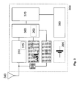
- FIG. 3 a block diagram of an electronic implant with integrated GSM modem is shown.
- a low-current GSM modem 310 including a SIM module 315 is integrated in a hermetically sealed housing 300 of the electronic implant.
- a control unit 360 controls the GSM modem 310.
- the GSM modem 310 is connected to a GSM antenna 340.
- An extremely low-power GSM field strength detector 330 is connected to the GSM antenna 340 via a matching network 350 as a field strength measuring unit with a programmable triggering threshold.
- This GSM field strength detector is also connected to the control unit 360.
- the control unit in turn is in turn connected to a message scheduler 370.
- the electronic implant contains a diagnostics and therapy control unit 380.
- This diagnostics and therapy control unit 380 is connected to the message scheduler 370 so that, triggered by diagnostic or therapeutic events, the message scheduler 370 can be influenced. This in turn is designed to request both event-triggered and periodic message transmissions. If such a message request is present, the control unit 360 is activated. This then periodically activates the field strength detector 330 at a time when a low power GSM connection can be established. If the field strength detector 330 indicates a suitable output condition (eg if it measures a sufficient mobile field strength), the control unit 360 activates the GSM modem 310 for dialing into the base station with the identification data of the SIM module 315.
- the output power of the GSM Module is adapted to the signal conditions and is significantly lower compared to conventional GSM modems.
- this arrangement includes a statistics unit 320 for statistically detecting the transmission success.
- This statistical unit 320 always records the transmission success rate relative to the GSM field strength measured before the connection establishment.
- This statistical detection is preferably carried out as a 3-dimensional Histogram, where the third dimension represents the time of day. This makes it possible to record transmission conditions that recur at specific times of the day (eg in the office or similar). The time recording can alternatively be extended to a whole week.
- the control unit 360 includes a unit for classifying the urgency of the message.
- a unit for classifying the urgency of the message is z.
- routine messages eg, remote follow-up data
- messages of medium urgency eg, VF episode with successful therapy
- emergency messages eg, unsuccessful maximum energy shock in the ICD.
- the controller assumes a different transmission success rate before the connection is established.
- FIG. 4 a two-stage GSM field strength detector according to a preferred embodiment is shown.
- the aim is to realize an extremely low-current detector.
- this GSM field strength detector has a first broadband detector stage 410, 420, 430 serving as a non-specific GSM field strength detector.
- the antenna 400 is connected to a broadband input network 410.
- the signal field strength is provided to a programmable trigger unit 430 which performs a threshold value comparison by means of an integrated comparator and possibly triggers an activation signal.
- input network 410, amplifier 420, and trigger unit 430 form the first broadband detector stage as a nonspecific GSM field strength detector, which activates a second specific frequency selective GSM field strength detector stage only when the input signal exceeds a programmable threshold for a certain time.
- Field strength measuring unit 440 is used. This is connected via a corresponding frequency-selective network 450 with the GSM antenna.
- the frequency-selective GSM field strength measuring unit 440 checks in addition to the field strength further specific signal characteristics z. B. a respective signal-to-noise ratio to increase the probability of a successful GSM dial-up. If these checks are positive, then a corresponding output signal is generated.
- ICD implantable cardioverter / defibrillator
- the battery load is at unchanged transmission scheme at 20% of its capacity.
- This battery capacity required for the data transmission is of the order of magnitude of the expected increase in battery capacity over the next few years with constant battery volumes.
- dial-in attempts / week means max. 2 dial-in attempts per week, if the first one is successful, the second attempt will not be started. The calculation assumes that the first dial-in attempt is associated with a 50% success rate.
- FIG. 5 shows the block diagram of an alternative implementation.
- the GSM modem 500 with antenna 530, the SIM module 505 and the field strength detector and matching network 510, 520 are powered by their own rechargeable battery 540.
- the medically critical functions of the electronic implant, d. H. Diagnostic and therapy control unit 580 and also the message scheduler 570 and controller 560 are powered by a primary cell as a power or voltage source, so that the regularly required recharging of the battery is not a security-related problem of the medical device, but only ensures the data transfer.
- FIG. 6 shows the in the description too FIG. 3 mentioned dial-up success statistics in the form of a histogram 600 of transmission success rates for a certain time of day.
- the transmission power can be additionally increased.
- the inventive solution is not limited to the use of GSM as a transmission standard, as well as other transmission methods, such as the mobile radio standards UMTS, HSDPA, HSUPA or LTE, but also Bluetooth, WLAN or the like can be used equally in place of GSM.
Landscapes
- Health & Medical Sciences (AREA)
- Engineering & Computer Science (AREA)
- Animal Behavior & Ethology (AREA)
- General Health & Medical Sciences (AREA)
- Biomedical Technology (AREA)
- Nuclear Medicine, Radiotherapy & Molecular Imaging (AREA)
- Radiology & Medical Imaging (AREA)
- Life Sciences & Earth Sciences (AREA)
- Veterinary Medicine (AREA)
- Public Health (AREA)
- Signal Processing (AREA)
- Computer Networks & Wireless Communication (AREA)
- Physics & Mathematics (AREA)
- Acoustics & Sound (AREA)
- Mobile Radio Communication Systems (AREA)
- Measuring And Recording Apparatus For Diagnosis (AREA)
- Electrotherapy Devices (AREA)
Description
- Die Erfindung betrifft ein dauerimplantierbares elektronisches Implantat, welches dazu ausgebildet ist mindestens einen technischen oder physiologischen Parameter zu erfassen. Insbesondere betrifft die Erfindung implantierbare Impulsgeneratoren wie Herzschrittmacher, Kardioverter/Defibrillatoren oder dergleichen.
- Die Fernüberwachung elektronischer Implantate wie Herzschrittmacher, implantierbare Defibrillatoren oder Neurostimulatoren gewinnt zunehmend an Bedeutung. Diese Implantate übertragen dabei in regelmäßigen Abständen (z. B. einmal täglich) oder ereignisgetriggert Daten an ein Fernüberwachungsserver, auf den wiederum über eine Datenverbindung der Arzt zugreifen und so die Fernüberwachung durchführen kann.
- Alle derzeit bekannten Lösungen sind dabei auf eine Relaisstation (z. B. BIOTRONIK Cardio Messenger) zur Übertragung der Daten aus dem elektronischen Implantat an ein Datenübertragungsnetzwerk (Mobilfunknetz, Telefonnetz, etc.) angewiesen. Bevorzugt kommt hier eine Übertragung der Daten des elektronischen Implantates zur Relaisstation via MICS-Band (z. T. auch ISM-Band) zum Einsatz.
- Nachteil dieser Lösung ist es, dass der Patient ein zusätzliches, kostenintensives externes Zusatzgerät in Reichweite des Implantates mitführen muss, um so die Datenübertragung vom Implantat zum Übertragungsnetzwerk zu gewährleisten. Diese externen Zusatzgeräte sind auch deswegen als Schwachpunkt dieser Übertragungskette anzusehen, da diese häufig vom Patienten nicht korrekt bedient werden oder sich nicht in Reichweite des Implantates befinden (Patientencompliance). Z. T. stoßen diese Geräte auch auf Ablehnung durch den Patienten und haben psychologische Nebenwirkungen, da der Patient ständig an das elektronische Implantat erinnert wird (Angst, Kontrollzwang, etc.).
-
Figur 1 zeigt den derzeitigen Stand der Technik. Ein elektronisches Implantat 110 besitzt einen MICS-Band Transceiver und sendet in periodische Abständen Signale, die Werte technischer und/oder physiologischer Parameter repräsentieren und die mit dem Implantat gemessen wurden, an eine Relaisstation 120, die sich in unmittelbarer Nähe des Patienten mit dem elektronische Implantat zum Übertragungszeitpunkt befinden muss. Diese Relaisstation 120 überträgt dann mittels eines integrierten GSM-Modems die gesendeten Daten an eine GSM-Basisstation 130, die dann wiederum diese Daten über ein Mobilfunknetzwerk 140 an einen Fernüberwachungsserver 150 überträgt und damit dem Arzt 160 zu Verfügung stellt. - Die Relaisstation 120 - genannt Patientengerät - kann in einer mobilen oder stationären Ausführung realisiert sein. Alternativ wird bei einem stationären Patientengerät auch eine Festnetztelefonverbindung für die Datenübertragung verwendet.
- Eine sichere Datenübertragung ist nur dann möglich, wenn das Patientengerät 120 eingeschaltet ist und sind in maximal 2-5 Metern Abstand zum elektronischen Implantat befindet.
- Der Erfindung liegt die Aufgabe zugrunde, eine Datenverbindung für die Fernüberwachung eines elektronischen Implantates zwischen Implantat und einem Mobilfunknetzwerk (z. B. einem GSM-Netz) ohne eine zusätzliche Relaisstation zu realisieren.
- Erfindungsgemäß wird diese Aufgabe gelöst durch ein dauerimplantierbares elektronisches Implantat, welches dazu ausgebildet ist, mindestens einen technischen oder physiologischen Parameter zu erfassen, und welches eine sich erschöpfende Strom- oder Spannungsquelle, also in der Regel eine Batterie, aufweist. Das elektronische Implantat besitzt ein stromarmes Mobilfunk-Modem mit geringer maximaler Sendeleistung, welches mit einer in das elektronische Implantat integrierten Mobilfunk Antenne verbunden ist. Die Angaben "stromarm" und "geringe maximale Sendeleistung" dienen dem besseren Verständnis des Zusammenhangs und beziehen sich auf heute übliche GSM-Modems zur Datenübertragung.
Außerdem besitzt das Implantat eine mit dieser Antenne oder einer zweiten Antenne verbundene stromarme Mobilfunk-Feldstärkemesseinheit und eine Steuereinheit, die mit der Feldstärkemesseinheit und dem Mobilfunk-Modem verbunden ist. Die Steuereinheit ist ausgebildet, eine Einwahl in ein Mobilfunknetz in Abhängigkeit - sowohl unter Berücksichtigung eines aktuellen Ausgangswertes der Feldstärkemesseinheit (also einem aktuellen Feldstärkewert)
- als auch der Dringlichkeit eines zu übertragenden Dateninhalts nur dann auszulösen, wenn der aktuelle Ausgangswert der Feldstärkemesseinheit einen für eine jeweilige Dringlichkeit spezifische Übertragungsmindesterfolgsquote indiziert.
- In einem einfachen Fall kann dies beispielsweise bedeuten, dass die Steuereinheit eine Einwahl nur dann auslöst, wenn die unter Berücksichtigung eines von der Feldstärkemesseinheit bestimmten Mobilfunk-Feldstärkewertes voraussichtlich erforderlichen Sendeleistung einen für eine jeweilige Dringlichkeit spezifischen Höchstwert nicht überschreitet.
- Hierbei wird die Integration eines GSM-Modems in ein elektronische Implantat als bekannt vorausgesetzt (siehe:
US 2007/0032832 A1 sowieUS 2004/0122 489 A1 ), wobei die ausUS 2007/0032832 A1 be kannte Lösung der Erschöpfbarkeit der Batterie eines elektronischen Dauerimplantats keine Rechnung trägt. Demgegenüber erlaubt es die erfindungsgemäße Lösung ein Mobilfunk-Modem in einem elektronischen Implantat so stromarm zu betreiben, das dessen Einsatz gemessen an der zu erwartenden Betriebszeitverkürzung durch die Datenübertragung gerechtfertigt ist. - Die Erfindung beruht auf der Annahme, dass der Träger eines elektronischen Implantates sich in Zukunft immer im Bereich von Mobilfunkzellen, beispielsweise GSM-Zellen aufhält, wobei ein oder mehrfachtäglich auch überdurchschnittlich gute Sende- und Empfangsbedingungen bestehen. Diese sollen mittels der Erfindung ausgenutzt werden und nur bei diesen Bedingungen soll die Verbindung zu einer Mobilfunk-Basisstation überhaupt aufgebaut werden.
- Für Patienten, bei denen diese Annahme nicht zutrifft, werden in Zukunft vorrausichtlich sog. Micro-GSM-Zellen für den Betrieb im häuslichen Umfeld von den GSM-Betreibern angeboten.
- Vorzugsweise ist das Mobilfunk-Modem ein GSM-Modem und die Mobilfunk-Feldstärkemesseinheit eine GSM-Feldstärkemesseinheit. Das elektronische Implantat enthält vorzugsweise ein Subscriber Identity Modul, beispielsweise in Form einer SIM Karte.
- Ferner weist das elektronische Implantat eine Statistik-Einheit auf, die mit der Steuereinheit verbunden oder Teil derselben ist und die ausgebildet ist, eine Einwahlerfolgsstatistik ausgelöster Einwahlen in Abhängigkeit von eines jeweiligen vor einem jeweiligen Einwahlversuch seitens der Mobilfunk-Feldstärkemesseinheit gemessenen Feldstärkewertes aufzuzeichnen. Hierbei kann die Steuereinheit ausgebildet sein, eine Einwahl zusätzlich unter Berücksichtigung der Einwahlerfolgsstatistik für einen jeweils gemessenen Mobilfunk-Feldstärkewert auszulösen.
- Weiter ist die Statistikeinheit ausgebildet, die Einwahlerfolgsstatistik unter Berücksichtigung des jeweiligen Einwahlzeitpunktes aufzuzeichnen und die Steuereinheit ist ausgebildet, anhand der Einwahlerfolgsstatistik den Zeitpunkt eines nächsten Einwahlzeitfensters und/oder Feldstärkemessfensters zu bestimmen. So kann die Häufigkeit erfolgreichen Verbindungsaufbaus bei wiederkehrenden Umgebungsbedingungen (z. B. guter GSM-Empfang am Arbeitsplatz) gesteigert werden. Auch kann der Energieaufwand für die Bestimmung der Übertragungsbedingungen durch eine jeweilige Feldstärkemessung reduziert werden.
- Die Erfindung ist durch Anspruch 1 definiert.
- Gemäß weiterer bevorzugter Ausführungsvarianten weist das elektronische Implantat zwei Strom- oder Spannungsquellen auf, von denen eine für die Versorgung einer Mobilfunk-Einheit unabhängig von übrigen Einheiten des elektronischen Implantates bestimmt ist und die als (vorzugsweise transkutan und drahtlos) wiederaufladbare Batterie ausgebildet ist. Die Mobilfunk-Einheit umfasst in dieser Ausführungsvariante vorzugsweise wenigstens das Mobilfunk-Modem und kann beispielsweise zusätzlich die Mobilfunk-Feldstärkemesseinheit umfassen.
- Vorzugsweise besitzt das elektronische Implantat neben der Mobilfunk-Feldstärkemesseinheit einen sehr unspezifischen GSM-Feldstärke-Detektor, der direkt oder vermittels der Steuereinheit dazu ausgebildet ist, die Mobilfunk-Feldstärkemesseinheit nur dann zu aktivieren, wenn der sehr unspezifische GSM-Feldstärke-Detektor eine Mindestfeldstärke (Schwellwert) anzeigt. Das elektronische Implantat kann hierzu einen Verstärker, einen Komparator zum Schwellwertvergleich und Triggereinheit zum Aktivieren der Feldstärkemesseinheit bei Überschreiten des Schwellwertes aufweisen.
- Die Steuereinheit ist vorzugsweise dazu ausgebildet, maximal einen Einwahlversuch innerhalb eines einstellbaren Zeitraums, z. B. eines Tages, auszulösen.
- Außerdem kann die Steuereinheit dazu ausgebildet sein, die Anzahl der Einwahlversuche innerhalb eines jeweiligen Zeitraums derart zu begrenzen, dass nur ein vorgegebener maximaler Anteil (z. B. 25%) der Kapazität der erschöpfbaren Strom- oder Spannungsquelle für eine Übertragung von Daten mittels des Mobilfunk-Modems verbraucht wird. Hierbei kann die Steuereinheit ausgebildet sein, eine Einwahl im Falle von Notfallnachrichten enthaltenden Dateninhalten unabhängig von der Kapazität der erschöpfbaren Strom- oder Spannungsquelle auszulösen.
- Weiterhin kann die Steuereinheit ausgebildet sein, eine Einwahl in ein Mobilfunk-Netz nur für Dateninhalte auszulösen, die durch ein seitens des elektronischen Implantats detektiertes technisches oder physiologisches Ereignis generiert sind. Dies können z. B. Notfallnachrichten sein, die durch die Detektion als gefährlich zu betrachtender Gesundheitszustände ausgelöst sind.
- Die Erfindung soll nun anhand eines Ausführungsbeispiels mit Bezug auf die Figuren näher erläutert werden. Von diesen zeigt:
- Fig. 1:
- den Stand der Technik;
- Fig. 2:
- die erfindungsgemäße Lösung als Gesamtsystem;
- Fig. 3:
- ein Blockschaltbild eines elektronischen Implantates mit integriertem GSM-Modem;
- Fig. 4:
- einen zweistufigen GSM-Feldstärkedetektor;
- Fig. 5:
- das Blockschaltbild einer alternativen Implementierung; und
- Fig. 6:
- die in der Beschreibung zu
Figur 3 erwähnte Sendeerfolgsstatistik. - In
Figur 2 ist die erfindungsgemäße Lösung als Teil eines Gesamtsystems dargestellt. Dieses umfasst ein elektronisches Implantat 210, in das ein GSM-Modem integriert ist, dass sich gesteuert durch eine Steuereinheit immer dann in eine GSM-Basisstation 230 einwählt, wenn die GSM-Band-Feldstärke eine stromarme Einwahl und Datenübertragung wahrscheinlich macht. Die weitere Übertragungskette mit Mobilfunknetzwerk 240, Fernüberwachungsserver 250 bis zum Arzt 260 bleibt von der Erfindung unbeeinflusst. - In
Figur 3 ist ein Blockschaltbild eines elektronischen Implantates mit integriertem GSM-Modem dargestellt. In ein hermetisch verschlossenes Gehäuse 300 des elektronischen Implantates ist ein stromarmes GSM-Modem 310 inklusive eines SIM-Moduls 315 integriert. Eine Steuereinheit 360 steuert das GSM-Modem 310. Das GSM-Modem 310 ist mit einer GSM-Antenne 340 verbunden. An die GSM-Antenne 340 ist über ein Anpassungsnetzwerk 350 ein extrem stromarmer GSM-Feldstärkedetektor 330 als Feldstärkemesseinheit mit programmierbarer Auslöse-Schwelle angeschlossen. Dieser GSM-Feldstärkedetektor ist ebenfalls mit der Steuereinheit 360 verbunden. Die Steuereinheit ist ihrerseits wiederum ist mit einem Message-Scheduler 370 verbunden. - Ferner enthält das elektronische Implantat eine Diagnostik und Therapiesteuereinheit 380. Diese Diagnostik und Therapiesteuereinheit 380 ist mit dem Message-Scheduler verbunden 370, so dass ausgelöst durch diagnostische oder therapeutische Ereignisse der Message-Scheduler 370 beeinflusst werden kann. Dieser wiederum ist ausgelegt, sowohl ereignisgetriggerte als auch periodische Nachrichtenübertragungen anzufordern. Liegt eine solche Nachrichtenanforderung vor, so wird die Steuereinheit 360 aktiviert. Diese aktiviert dann in periodischen Abständen den Feldstärkedetektor 330 um einen Zeitpunkt zu detektieren, wenn eine GSM-Verbindung mit niedriger Ausgangsleistung hergestellt werden kann. Meldet der Feldstärkedetektor 330 eine geeignete Ausgangsbedingung (z. B. wenn er eine ausreichende Mobilfunk-Feldstärke misst), so aktiviert die Steuereinheit 360 das GSM-Modem 310 zur Einwahl in die Basisstation mit den Identifikationsdaten des SIM-Moduls 315. Die Ausgangsleistung des GSM-Moduls wird an die Signalbedingungen angepasst und ist gegenüber herkömmlichen GSM-Modems deutlich geringer.
- Zusätzlich beinhaltet diese Anordnung eine Statistik-Einheit 320 zur statistischen Erfassung des Übertragungserfolges. Diese Statistikeinheit 320 erfasst dabei immer die Übertragungserfolgsrate bezogen auf die vor dem Verbindungsaufbau gemessene GSM-Feldstärke. Diese statistische Erfassung erfolgt dabei bevorzugt als ein 3-dimensionales Histogramm, wobei die dritte Dimension die Tageszeit darstellt. So ist es möglich, Sendebedingungen zu erfassen, die zu bestimmten Tageszeiten wiederkehren (z. B. im Büro o.ä.). Die zeitliche Erfassung kann alternativ auch auf eine ganze Woche erweitert werden.
- Die Steuereinheit 360 wiederum beinhaltet eine Einheit zur Klassifikation der Dringlichkeit der Nachricht. Hier wird z. B. zwischen Routinenachrichten (z. B. Remote Follow-up Daten), Nachrichten mittlerer Dringlichkeit (z. B. VF-Episode mit erfolgreicher Therapie) und Notfallnachrichten (z. B. nicht erfolgreicher Maximalenergieschock im ICD) unterschieden. Abhängig von der in dieser Klassifikationseinheit bestimmten Dringlichkeit wird von Controller eine unterschiedliche Sendeerfolgsrate vor dem Verbindungsaufbau vorausgesetzt.
- In
Figur 4 ist ein zweistufiger GSM-Feldstärkedetektor gemäß einer bevorzugten Ausführungsvariante dargestellt. Ziel ist es, einen extrem stromarmen Detektor zu realisieren. Aus diesem Grund besitzt dieser GSM-Feldstärkedetektor eine erste breitbandige Detektorstufe 410, 420, 430, die als unspezifischer GSM-Feldstärkedetektor dient. Die Antenne 400 ist mit einen breitbandigen Eingangsnetzwerk 410 verbunden. Nach der GSM-Signalverstärkung durch einen Verstärker 420 wird die Signalfeldstärke einer programmierbaren Triggereinheit 430 zur Verfügung gestellt die mittels eines integrierten Komparators einen Schwellwertvergleich durchführt und ggf. ein Aktivierungssignal auslöst. Da Eingangsnetzwerk 410, der Verstärker 420 und die Triggereinheit 430 bilden die erste breitbandige Detektorstufe als unspezifischem GSM-Feldstärkedetektor, der erst wenn das Eingangssignal eine programmierbare Schwelle für eine bestimmte Zeit überschreitet, eine zweite spezifische, frequenzselektive GSM-Feldstärkedetektorstufe aktiviert, die als GSM-Feldstärkemesseinheit 440 dient. Diese ist über ein entsprechend frequenzselektives Netzwerk 450 mit der GSM-Antenne verbunden. - Die frequenzselektive GSM-Feldstärkemesseinheit 440 prüft neben der Feldstärke weitere spezifische Signalcharakteristika z. B. ein jeweiliges Signal-Rausch-Verhältnis, um die Wahrscheinlichkeit einer erfolgreichen GSM-Einwahl zu steigern. Sind diese Prüfungen positive, dann wird ein entsprechendes Ausgangssignal generiert.
- Im Folgenden soll dargestellt werden, dass bei Anwendung der erfindungsgemäßen Lösung die Applikation eines GSM-Modems in einem elektronischen Implantat am Beispiel eines implantierbaren Kardioverter/Defibrillators (ICD) möglich ist:
-
Batteriekapazität: -2,3 Ah bei einer Betriebsspannung von 3V Typ. Betriebszeit eines ICD: 6 Jahre Datenübertragungsschema für Fernüberwachung: 1 Einwahlversuch / Tag + 5 Ereignisnachrichten / Jahr -
Einwahldauer: bis 10sec Stromaufnahme bei einer Betriebsspannung von 3V: bis 1 A
D. h. mit derzeitigem Einwahlprotokoll ist eine GSM-Lösung nicht möglich. -
Batteriekapazität: ~2,3 Ah bei einer Betriebsspannung von 3V Typ. Betriebszeit eines ICD: 6 Jahre Datenübertragungsschema für Fernüberwachung: 1 Einwahlversuch / Tag + 5 Ereignisnachrichten / Jahr -
Einwahldauer: bis 3 sec Stromaufnahme bei einer Betriebsspannung von 3V: bis 0,25 A - Mit der erfindungsgemäßen Lösung ist eine GSM-Einwahl des Implantates möglich. Die Batteriebelastung liegt bei unverändertem Übertragungsschema bei 20% ihrer Kapazität. Diese für die Datenübertragung benötigte Batteriekapazität liegt in der Größenordnung der in den nächsten Jahren zu erwartenden Steigerung der Batteriekapazität bei gleichbleibenden Batterievolumen.
-
Batteriekapazität: ~2,3 Ah bei einer Betriebsspannung von 3V Typische Betriebszeit eines ICD: 6 Jahre Datenübertragungsschema für Fernüberwachung: 1,5 Einwahlversuche / Woche 5 Ereignisnachrichten / Jahr - 1,5 Einwahlversuche / Woche bedeutet, es finden max. 2 Einwahlversuche pro Woche statt, ist der erste erfolgreich, dann wird der 2. versuch nicht gestartet. In der Berechnung wird davon ausgegangen, dass der erste Einwahlversuch mit einer 50% Erfolgsrate verbunden ist.
-
Einwahldauer: bis 3 sec Stromaufnahme bei einer Betriebsspannung von 3V: bis 0,25 A - Mit der erfindungsgemäßen Lösung und einem angepassten Datenübertragungsprotokoll ist die Applikation eines GSM-Modems in einen ICD ohne nennenswerte Beschränkung der Betriebsdauer (<5%) des ICD möglich.
-
Figur 5 zeigt das Blockschaltbild einer alternativen Implementierung. Gemäß dieser Variante werden das GSM-Modem 500 mit Antenne 530, das SIM-Modul 505 und der Feldstärkedetektor nebst Anpassungsnetzwerk 510, 520 durch eine eigene wiederaufladbare Batterie 540 versorgt. Die Aufladung dieser Batterie 540 erfolgt z. B. über eine außerhalb des metallischen Implantatgehäuses angebrachte Ladespule 550. - Die medizinisch kritischen Funktionen des elektronischen Implantates, d. h. Diagnostik und Therapiesteuereinheit 580 und auch der Message-Scheduler 570 und Controller 560 werden von einer Primärzelle als Strom- oder Spannungsquelle gespeist, so dass die regelmäßig erforderliche Wiederaufladung des Akkus kein sicherheitsrelevantes Problem des Medizinproduktes darstellt, sondern lediglich die Datenübertragung gewährleistet.
-
Figur 6 zeigt die in der Beschreibung zuFigur 3 erwähnte Einwahlerfolgsstatistik in Form eines Histogramms 600 von Übertragungserfolgsquoten für eine bestimmte Tageszeit. - In den einzelnen Histogrammklassen wird festgehalten, ob eine Datenübertragung bezogen auf jeweils eine vor dem Verbindungsaufbau gemessenen Feldstärkeklasse erfolgreich beendet werden konnte.
- Für die einzelnen Dringlichkeitsklassen der Nachrichten sind unterschiedliche Grenzen (610...630) (Übertragungsmindesterfolgsquoten) für die geforderte Übertragungserfolgsquote festgelegt. Ein Verbindungsaufbau findet nur dann statt, wenn die im Histogramm erfasste Übertragungserfolgsquote die für die jeweilige Dringlichkeit der Nachricht programmierte Schwelle (Übertragungsmindesterfolgsquote) überschreitet. So wird ein Sendeversuch bei einer Notfallnachricht bereits bei einer kleinen Erfolgsquote (630) gestartet, bei einer Routinenachricht hingegen nur bei einer sehr guten Erfolgsquote oberhalb der mit 610 gekennzeichnet Übertragungsmindesterfolgsquote.
- Optional kann bei den Notfallnachrichten in Kombination mit einer schlechten Übertragungserfolgsquote (630) die Sendeleistung zusätzlich heraufgesetzt werden.
- Die erfindungsgemäße Lösung ist nicht auf die Verwendung von GSM als Übertragungsstandard limitiert, ebenso können weitere Übertragungsverfahren, wie zum Beispiel nach den Mobilfunkstandards UMTS, HSDPA, HSUPA oder LTE, aber auch Bluetooth, WLAN oder ähnliche gleichermaßen an Stelle von GSM verwendet werden.
Claims (11)
- Dauerimplantierbares elektronisches Implantat, welches dazu ausgebildet ist mindestens einen technischen oder physiologischen Parameter zu erfassen, und welches eine sich erschöpfende Strom- oder Spannungsquelle (390) aufweist, sowie:- ein stromarmes Mobilfunk-Modem (310) mit geringer maximaler Sendeleistung enthält, welches mit einer in das elektronische Implantat integrierten Mobilfunk Antenne (340) verbunden ist,- einer mit dieser Antenne oder einer zweiten Antenne verbundenen stromarmen Mobilfunk-Feldstärkemesseinheit (330) und- einer Steuereinheit (360), die mit der Feldstärkemesseinheit 330) und dem Mobilfunk-Modem (310) verbunden und derart ausgebildet ist, eine Einwahl in ein Mobilfunknetz in Abhängigkeit- sowohl unter Berücksichtigung eines aktuellen Ausgangswertes der Feldstärkemesseinheit (330)- als auch der Dringlichkeit eines zu übertragenden Dateninhalts nur dann auszulösen, wenn der aktuelle Ausgangswert der Feldstärkemesseinheit (330) eine für eine jeweilige Dringlichkeit spezifische Übertragungsmindesterfolgquote indiziert und- einer Statistikeinheit (320), die mit der Steuereinheit (360) verbunden oder Teil derselben ist und die ausgebildet ist, eine Einwahlerfolgsstatistik ausgelöster Einwahlen in Abhängigkeit von eines jeweiligen vor einem jeweiligen Einwahlversuch seitens der Mobilfunk-Feldstärkemesseinheit (330) gemessenen Feldstärkewertes aufzuzeichnen;dadurch gekennzeichnet,
dass die Statistikeinheit (320) ausgebildet ist, die Einwahlerfolgsstatistik unter Berücksichtigung des jeweiligen Einwahlzeitpunktes aufzuzeichnen und dass die Steuereinheit (360) ausgebildet ist, anhand der Einwahlerfolgsstatistik den Zeitpunkt eines nächsten Einwahlzeitfensters und/oder Feldstärkemessfensters zu bestimmen. - Elektronisches Implantat nach Anspruch 1, dadurch gekennzeichnet, dass das Mobilfunk-Modem (310) ein GSM-Modem ist und dass die Mobilfunk-Feldstärkemesseinheit (330) eine GSM-Feldstärkemesseinheit ist.
- Elektronisches Implantat nach Anspruch 1 oder 2, dadurch gekennzeichnet, dass das elektronische Implantat ein Subscriber Identity Modul (315) enthält.
- Elektronisches Implantat nach einem der Ansprüche 1 bis 3, dadurch gekennzeichnet, dass die Steuereinheit (360) ausgebildet ist, eine Einwahl zusätzlich unter Berücksichtigung der Einwahlerfolgsstatistik für einen jeweils gemessenen Mobilfunk-Feldstärkewert auszulösen.
- Elektronisches Implantat nach einem der Ansprüche 1 bis 4, dadurch gekennzeichnet, dass das elektronische Implantat zwei Strom- oder Spannungsquellen (540, 590) aufweist, von denen eine (540) für die Versorgung einer Mobilfunk-Einheit unabhängig von übrigen Einheiten des elektronischen Implantates bestimmt ist und die als wiederaufladbare Batterie ausgebildet ist.
- Elektronisches Implantat nach Anspruch 5, dadurch gekennzeichnet, dass die Mobilfunk-Einheit wenigstens das Mobilfunk-Modem (500) umfasst.
- Elektronisches Implantat nach einem der Ansprüche 1 bis 6, dadurch gekennzeichnet, dass das elektronische Implantat neben der Mobilfunk-Feldstärkemesseinheit (440) einen vergleichsweise unspezifischen GSM-Feldstärke-Detektor (410, 430, 430) aufweist, und die Steuereinheit ausgebildet ist, die Mobilfunk-Feldstärkemesseinheit (440) nur dann zu aktivieren, wenn der sehr unspezifische GSM-Feldstärke-Detektor (410, 430, 430) eine Mindestfeldstärke anzeigt.
- Elektronisches Implantat nach einem der Ansprüche 1 bis 7, dadurch gekennzeichnet, dass die Steuereinheit (360) ausgebildet ist, maximal einen Einwahlversuch innerhalb eines einstellbaren Zeitraums auszulösen.
- Elektronisches Implantat nach einem der Ansprüche 1 bis 8, dadurch gekennzeichnet, dass die Steuereinheit (360) ausgebildet ist, die Anzahl der Einwahlversuche innerhalb eines jeweiligen Zeitraums derart zu begrenzen, dass nur ein vorgegebener maximaler Anteil der Kapazität der erschöpfbaren Strom- oder Spannungsquelle (390) für eine Übertragung von Daten mittels des Mobilfunk-Modems verbraucht wird.
- Elektronisches Implantat nach Anspruch 9, dadurch gekennzeichnet, dass die Steuereinheit (360) ausgebildet ist, eine Einwahl im Falle von Notfallnachrichten enthaltenden Dateninhalten unabhängig von der Kapazität der erschöpfbaren Strom- oder Spannungsquelle auszulösen.
- Elektronisches Implantat nach einem der Ansprüche 1 bis 10, dadurch gekennzeichnet, dass die Steuereinheit (360) ausgebildet ist, eine Einwahl in ein Mobilfunk-Netz nur für Dateninhalte auszulösen, die durch ein seitens des elektronischen Implantats detektiertes technisches oder physiologisches Ereignis generiert sind.
Applications Claiming Priority (1)
| Application Number | Priority Date | Filing Date | Title |
|---|---|---|---|
| DE102008054658A DE102008054658A1 (de) | 2008-12-15 | 2008-12-15 | Implantierbares medizinisches Gerät mit Mobilfunk-Modem |
Publications (3)
| Publication Number | Publication Date |
|---|---|
| EP2196239A2 EP2196239A2 (de) | 2010-06-16 |
| EP2196239A3 EP2196239A3 (de) | 2010-08-04 |
| EP2196239B1 true EP2196239B1 (de) | 2012-09-12 |
Family
ID=41664601
Family Applications (1)
| Application Number | Title | Priority Date | Filing Date |
|---|---|---|---|
| EP09177444A Not-in-force EP2196239B1 (de) | 2008-12-15 | 2009-11-30 | Implantierbares medizinisches Gerät mit Mobilfunk-Modem |
Country Status (3)
| Country | Link |
|---|---|
| US (1) | US8285246B2 (de) |
| EP (1) | EP2196239B1 (de) |
| DE (1) | DE102008054658A1 (de) |
Families Citing this family (5)
| Publication number | Priority date | Publication date | Assignee | Title |
|---|---|---|---|---|
| US20120165616A1 (en) * | 2010-12-27 | 2012-06-28 | Nir Geva | Portable monitoring unit and a method for monitoring a monitored person |
| EP2510975A1 (de) | 2011-04-14 | 2012-10-17 | BIOTRONIK SE & Co. KG | Herzstimulator |
| CN104683511A (zh) * | 2013-12-02 | 2015-06-03 | 王基旆 | 具有低周波脉冲功能的智能型手机 |
| US10338188B2 (en) * | 2017-06-22 | 2019-07-02 | Microsoft Technology Licensing, Llc | Location assistance with a dynamically updated beacon payload from an electronic device |
| GB2583531A (en) * | 2019-05-03 | 2020-11-04 | Lois Medical Ltd | Monitoring device and method |
Family Cites Families (20)
| Publication number | Priority date | Publication date | Assignee | Title |
|---|---|---|---|---|
| US6078816A (en) * | 1994-08-02 | 2000-06-20 | Sony Corporation | Method and apparatus for establishing clear wireless communication |
| US7548787B2 (en) | 2005-08-03 | 2009-06-16 | Kamilo Feher | Medical diagnostic and communication system |
| US6497655B1 (en) | 1999-12-17 | 2002-12-24 | Medtronic, Inc. | Virtual remote monitor, alert, diagnostics and programming for implantable medical device systems |
| US7060031B2 (en) | 1999-12-17 | 2006-06-13 | Medtronic, Inc. | Method and apparatus for remotely programming implantable medical devices |
| US6442432B2 (en) | 1999-12-21 | 2002-08-27 | Medtronic, Inc. | Instrumentation and software for remote monitoring and programming of implantable medical devices (IMDs) |
| US20010037220A1 (en) | 1999-12-21 | 2001-11-01 | Merry Randy L. | Integrated software system for implantable medical device installation and management |
| US6920360B2 (en) | 1999-12-21 | 2005-07-19 | Medtronic, Inc. | Large-scale processing loop for implantable medical devices |
| US6564104B2 (en) | 1999-12-24 | 2003-05-13 | Medtronic, Inc. | Dynamic bandwidth monitor and adjuster for remote communications with a medical device |
| US6718171B1 (en) | 2000-06-26 | 2004-04-06 | Denso Corporation | Robust and efficient reacquisition after call release |
| NZ507800A (en) | 2000-10-26 | 2003-06-30 | Interag | Device for herd control and/or monitoring procedures |
| DE10202448A1 (de) * | 2002-01-22 | 2003-08-07 | T Mobile Deutschland Gmbh | Verfahren und Einrichtung zur Überwachung der Körperfunktionen und/oder der körperlichen Verfassung eines Lebewesens |
| CA2483283A1 (en) | 2002-04-22 | 2003-11-20 | Medtronic, Inc. | Seamless communication between an implantable medical device and a remote system |
| US7395117B2 (en) * | 2002-12-23 | 2008-07-01 | Cardiac Pacemakers, Inc. | Implantable medical device having long-term wireless capabilities |
| AU2003216230A1 (en) * | 2003-02-10 | 2004-09-06 | Nielsen Media Research, Inc. | Methods and apparatus to adaptively gather audience information data |
| KR20050075477A (ko) * | 2004-01-15 | 2005-07-21 | 삼성전자주식회사 | Mimo 스테이션 간에 통신하는 방법 |
| US20070258395A1 (en) * | 2006-04-28 | 2007-11-08 | Medtronic Minimed, Inc. | Wireless data communication protocols for a medical device network |
| DE102006039345A1 (de) * | 2006-08-22 | 2008-03-06 | Biotronik Crm Patent Ag | Elektromedizinisches Implantat |
| US8428528B2 (en) * | 2007-10-24 | 2013-04-23 | Biotronik Crm Patent Ag | Radio communications system designed for a low-power receiver |
| US8108044B2 (en) * | 2008-03-27 | 2012-01-31 | Medtronic, Inc. | Method and apparatus for the staged detection of RF energy |
| US8059628B2 (en) * | 2008-04-07 | 2011-11-15 | Medtronic, Inc. | Low power multiple channel mixing architecture for detecting wake-up signals and related falsing protection algorithm |
-
2008
- 2008-12-15 DE DE102008054658A patent/DE102008054658A1/de not_active Withdrawn
-
2009
- 2009-11-30 US US12/627,101 patent/US8285246B2/en not_active Expired - Fee Related
- 2009-11-30 EP EP09177444A patent/EP2196239B1/de not_active Not-in-force
Also Published As
| Publication number | Publication date |
|---|---|
| EP2196239A3 (de) | 2010-08-04 |
| DE102008054658A1 (de) | 2010-06-17 |
| US20100152550A1 (en) | 2010-06-17 |
| EP2196239A2 (de) | 2010-06-16 |
| US8285246B2 (en) | 2012-10-09 |
Similar Documents
| Publication | Publication Date | Title |
|---|---|---|
| EP1062982B1 (de) | Verfahren zur Datenabfrage bei der Implantatsnachsorge | |
| EP1062981B1 (de) | Verfahren und System zur Datenübertragung bei der Implantatsüberwachung | |
| EP1070517B1 (de) | Sender für die Telemetrieeinrichtung eines Implantats | |
| EP1062984B1 (de) | Vorrichtung zur Übertragung von Daten insbesondere aus einem elektromedizinischen Implantat | |
| DE60212040T2 (de) | Telemetriesystem im Frequenzsprungbetrieb für eine implantierbare medizinische Vorrichtung | |
| EP1062985B1 (de) | Implantat mit Nah-und Fernfeldtelemetrie | |
| EP1062983B1 (de) | Elektromedizinisches Implantat | |
| DE69634689T2 (de) | Implantierbarer stimulator,der mit einer wiederaufladbaren, kapazitiven energiequelle versehen ist | |
| DE19844296A1 (de) | Anordnung zur Patientenüberwachung | |
| DE69736990T2 (de) | Digitales Übertragungssystem | |
| EP2196239B1 (de) | Implantierbares medizinisches Gerät mit Mobilfunk-Modem | |
| DE19930263A1 (de) | Verfahren und Vorrichtung zur Datenübertragung zwischen einem elektromedizinischen Implantat und einem externen Gerät | |
| DE69031090T2 (de) | Vorrichtung zur Bestimmung des Batterietyps und Modifikation der Betriebsmerkmale | |
| DE69417609T2 (de) | Räumlich getrennte Kontrollvorrichtung für einen implantierbaren Stimulator für das Gewebewachstum | |
| US7313529B2 (en) | Portable extender for data transmission within a medical device communication system | |
| DE3687098T2 (de) | Automatisches personalueberwachungssystem. | |
| EP0830878A1 (de) | Vorrichtung zur Rejektionsdiagnostik nach Organtransplantationen | |
| DE102008043451A1 (de) | Modulares Universalprogrammiergerät | |
| DE10009882A1 (de) | Mobiles Telekommunikations-Endgerät, insbesondere Mobiltelefon | |
| EP3258284B1 (de) | Betrieb einer magnetresonanzvorrichtung unter berücksichtigung von implantat-trägern | |
| EP3284517A2 (de) | Elektrodenleitung, implantat und verfahren zur identifikation einer elektrodenleitung | |
| DE10115896C2 (de) | Lösbar mit einem Hörgerät verbindbare Sende- und/oder Empfangseinheit sowie programmierbares Hörgerät | |
| EP3298857A1 (de) | Verfahren zur implementierung von sicherheitsregeln in einem endgerät | |
| DE10008411A1 (de) | Verfahren zur Aufnahme und Übertragung eines mehrkanaligen EKG und Anordnung als tragbarer Recorder zur Durchführung des Verfahrens | |
| DE102009000728A1 (de) | Verfahren zur Bestimmung einer Stromversorgungs-Zustandsgröße in einem aktiven medizinischen Implantat |
Legal Events
| Date | Code | Title | Description |
|---|---|---|---|
| PUAI | Public reference made under article 153(3) epc to a published international application that has entered the european phase |
Free format text: ORIGINAL CODE: 0009012 |
|
| AK | Designated contracting states |
Kind code of ref document: A2 Designated state(s): AT BE BG CH CY CZ DE DK EE ES FI FR GB GR HR HU IE IS IT LI LT LU LV MC MK MT NL NO PL PT RO SE SI SK SM TR |
|
| AX | Request for extension of the european patent |
Extension state: AL BA RS |
|
| PUAL | Search report despatched |
Free format text: ORIGINAL CODE: 0009013 |
|
| AK | Designated contracting states |
Kind code of ref document: A3 Designated state(s): AT BE BG CH CY CZ DE DK EE ES FI FR GB GR HR HU IE IS IT LI LT LU LV MC MK MT NL NO PL PT RO SE SI SK SM TR |
|
| AX | Request for extension of the european patent |
Extension state: AL BA RS |
|
| 17P | Request for examination filed |
Effective date: 20110114 |
|
| 17Q | First examination report despatched |
Effective date: 20110120 |
|
| R17C | First examination report despatched (corrected) |
Effective date: 20110209 |
|
| RIC1 | Information provided on ipc code assigned before grant |
Ipc: H04W 60/00 20090101ALI20120110BHEP Ipc: H04W 88/02 20090101ALN20120110BHEP Ipc: H04W 52/24 20090101ALI20120110BHEP Ipc: A61N 1/372 20060101AFI20120110BHEP |
|
| GRAP | Despatch of communication of intention to grant a patent |
Free format text: ORIGINAL CODE: EPIDOSNIGR1 |
|
| RIC1 | Information provided on ipc code assigned before grant |
Ipc: H04W 60/00 20090101ALI20120523BHEP Ipc: H04W 88/02 20090101ALN20120523BHEP Ipc: H04W 52/24 20090101ALI20120523BHEP Ipc: A61N 1/372 20060101AFI20120523BHEP |
|
| GRAS | Grant fee paid |
Free format text: ORIGINAL CODE: EPIDOSNIGR3 |
|
| GRAA | (expected) grant |
Free format text: ORIGINAL CODE: 0009210 |
|
| AK | Designated contracting states |
Kind code of ref document: B1 Designated state(s): AT BE BG CH CY CZ DE DK EE ES FI FR GB GR HR HU IE IS IT LI LT LU LV MC MK MT NL NO PL PT RO SE SI SK SM TR |
|
| REG | Reference to a national code |
Ref country code: GB Ref legal event code: FG4D Free format text: NOT ENGLISH |
|
| REG | Reference to a national code |
Ref country code: CH Ref legal event code: EP |
|
| REG | Reference to a national code |
Ref country code: AT Ref legal event code: REF Ref document number: 574748 Country of ref document: AT Kind code of ref document: T Effective date: 20120915 |
|
| REG | Reference to a national code |
Ref country code: IE Ref legal event code: FG4D Free format text: LANGUAGE OF EP DOCUMENT: GERMAN |
|
| REG | Reference to a national code |
Ref country code: DE Ref legal event code: R096 Ref document number: 502009004719 Country of ref document: DE Effective date: 20121108 |
|
| REG | Reference to a national code |
Ref country code: SE Ref legal event code: TRGR |
|
| PG25 | Lapsed in a contracting state [announced via postgrant information from national office to epo] |
Ref country code: LT Free format text: LAPSE BECAUSE OF FAILURE TO SUBMIT A TRANSLATION OF THE DESCRIPTION OR TO PAY THE FEE WITHIN THE PRESCRIBED TIME-LIMIT Effective date: 20120912 Ref country code: FI Free format text: LAPSE BECAUSE OF FAILURE TO SUBMIT A TRANSLATION OF THE DESCRIPTION OR TO PAY THE FEE WITHIN THE PRESCRIBED TIME-LIMIT Effective date: 20120912 Ref country code: NO Free format text: LAPSE BECAUSE OF FAILURE TO SUBMIT A TRANSLATION OF THE DESCRIPTION OR TO PAY THE FEE WITHIN THE PRESCRIBED TIME-LIMIT Effective date: 20121212 Ref country code: CY Free format text: LAPSE BECAUSE OF FAILURE TO SUBMIT A TRANSLATION OF THE DESCRIPTION OR TO PAY THE FEE WITHIN THE PRESCRIBED TIME-LIMIT Effective date: 20120912 Ref country code: HR Free format text: LAPSE BECAUSE OF FAILURE TO SUBMIT A TRANSLATION OF THE DESCRIPTION OR TO PAY THE FEE WITHIN THE PRESCRIBED TIME-LIMIT Effective date: 20120912 |
|
| REG | Reference to a national code |
Ref country code: NL Ref legal event code: VDEP Effective date: 20120912 |
|
| REG | Reference to a national code |
Ref country code: LT Ref legal event code: MG4D Effective date: 20120912 |
|
| PG25 | Lapsed in a contracting state [announced via postgrant information from national office to epo] |
Ref country code: LV Free format text: LAPSE BECAUSE OF FAILURE TO SUBMIT A TRANSLATION OF THE DESCRIPTION OR TO PAY THE FEE WITHIN THE PRESCRIBED TIME-LIMIT Effective date: 20120912 Ref country code: SI Free format text: LAPSE BECAUSE OF FAILURE TO SUBMIT A TRANSLATION OF THE DESCRIPTION OR TO PAY THE FEE WITHIN THE PRESCRIBED TIME-LIMIT Effective date: 20120912 Ref country code: GR Free format text: LAPSE BECAUSE OF FAILURE TO SUBMIT A TRANSLATION OF THE DESCRIPTION OR TO PAY THE FEE WITHIN THE PRESCRIBED TIME-LIMIT Effective date: 20121213 |
|
| PGFP | Annual fee paid to national office [announced via postgrant information from national office to epo] |
Ref country code: SE Payment date: 20121122 Year of fee payment: 4 |
|
| PG25 | Lapsed in a contracting state [announced via postgrant information from national office to epo] |
Ref country code: ES Free format text: LAPSE BECAUSE OF FAILURE TO SUBMIT A TRANSLATION OF THE DESCRIPTION OR TO PAY THE FEE WITHIN THE PRESCRIBED TIME-LIMIT Effective date: 20121223 Ref country code: NL Free format text: LAPSE BECAUSE OF FAILURE TO SUBMIT A TRANSLATION OF THE DESCRIPTION OR TO PAY THE FEE WITHIN THE PRESCRIBED TIME-LIMIT Effective date: 20120912 Ref country code: RO Free format text: LAPSE BECAUSE OF FAILURE TO SUBMIT A TRANSLATION OF THE DESCRIPTION OR TO PAY THE FEE WITHIN THE PRESCRIBED TIME-LIMIT Effective date: 20120912 Ref country code: EE Free format text: LAPSE BECAUSE OF FAILURE TO SUBMIT A TRANSLATION OF THE DESCRIPTION OR TO PAY THE FEE WITHIN THE PRESCRIBED TIME-LIMIT Effective date: 20120912 Ref country code: CZ Free format text: LAPSE BECAUSE OF FAILURE TO SUBMIT A TRANSLATION OF THE DESCRIPTION OR TO PAY THE FEE WITHIN THE PRESCRIBED TIME-LIMIT Effective date: 20120912 Ref country code: IS Free format text: LAPSE BECAUSE OF FAILURE TO SUBMIT A TRANSLATION OF THE DESCRIPTION OR TO PAY THE FEE WITHIN THE PRESCRIBED TIME-LIMIT Effective date: 20130112 |
|
| BERE | Be: lapsed |
Owner name: BIOTRONIK CRM PATENT A.G. Effective date: 20121130 |
|
| PG25 | Lapsed in a contracting state [announced via postgrant information from national office to epo] |
Ref country code: PL Free format text: LAPSE BECAUSE OF FAILURE TO SUBMIT A TRANSLATION OF THE DESCRIPTION OR TO PAY THE FEE WITHIN THE PRESCRIBED TIME-LIMIT Effective date: 20120912 Ref country code: PT Free format text: LAPSE BECAUSE OF FAILURE TO SUBMIT A TRANSLATION OF THE DESCRIPTION OR TO PAY THE FEE WITHIN THE PRESCRIBED TIME-LIMIT Effective date: 20130114 Ref country code: SK Free format text: LAPSE BECAUSE OF FAILURE TO SUBMIT A TRANSLATION OF THE DESCRIPTION OR TO PAY THE FEE WITHIN THE PRESCRIBED TIME-LIMIT Effective date: 20120912 |
|
| PLBE | No opposition filed within time limit |
Free format text: ORIGINAL CODE: 0009261 |
|
| STAA | Information on the status of an ep patent application or granted ep patent |
Free format text: STATUS: NO OPPOSITION FILED WITHIN TIME LIMIT |
|
| PG25 | Lapsed in a contracting state [announced via postgrant information from national office to epo] |
Ref country code: DK Free format text: LAPSE BECAUSE OF FAILURE TO SUBMIT A TRANSLATION OF THE DESCRIPTION OR TO PAY THE FEE WITHIN THE PRESCRIBED TIME-LIMIT Effective date: 20120912 Ref country code: BG Free format text: LAPSE BECAUSE OF FAILURE TO SUBMIT A TRANSLATION OF THE DESCRIPTION OR TO PAY THE FEE WITHIN THE PRESCRIBED TIME-LIMIT Effective date: 20121212 |
|
| 26N | No opposition filed |
Effective date: 20130613 |
|
| PG25 | Lapsed in a contracting state [announced via postgrant information from national office to epo] |
Ref country code: IT Free format text: LAPSE BECAUSE OF FAILURE TO SUBMIT A TRANSLATION OF THE DESCRIPTION OR TO PAY THE FEE WITHIN THE PRESCRIBED TIME-LIMIT Effective date: 20120912 Ref country code: BE Free format text: LAPSE BECAUSE OF NON-PAYMENT OF DUE FEES Effective date: 20121130 |
|
| REG | Reference to a national code |
Ref country code: DE Ref legal event code: R097 Ref document number: 502009004719 Country of ref document: DE Effective date: 20130613 |
|
| PG25 | Lapsed in a contracting state [announced via postgrant information from national office to epo] |
Ref country code: MT Free format text: LAPSE BECAUSE OF FAILURE TO SUBMIT A TRANSLATION OF THE DESCRIPTION OR TO PAY THE FEE WITHIN THE PRESCRIBED TIME-LIMIT Effective date: 20120912 |
|
| PG25 | Lapsed in a contracting state [announced via postgrant information from national office to epo] |
Ref country code: MC Free format text: LAPSE BECAUSE OF NON-PAYMENT OF DUE FEES Effective date: 20121130 Ref country code: TR Free format text: LAPSE BECAUSE OF FAILURE TO SUBMIT A TRANSLATION OF THE DESCRIPTION OR TO PAY THE FEE WITHIN THE PRESCRIBED TIME-LIMIT Effective date: 20120912 |
|
| PG25 | Lapsed in a contracting state [announced via postgrant information from national office to epo] |
Ref country code: LU Free format text: LAPSE BECAUSE OF NON-PAYMENT OF DUE FEES Effective date: 20121130 Ref country code: SM Free format text: LAPSE BECAUSE OF FAILURE TO SUBMIT A TRANSLATION OF THE DESCRIPTION OR TO PAY THE FEE WITHIN THE PRESCRIBED TIME-LIMIT Effective date: 20120912 |
|
| GBPC | Gb: european patent ceased through non-payment of renewal fee |
Effective date: 20131130 |
|
| REG | Reference to a national code |
Ref country code: SE Ref legal event code: EUG |
|
| PG25 | Lapsed in a contracting state [announced via postgrant information from national office to epo] |
Ref country code: HU Free format text: LAPSE BECAUSE OF FAILURE TO SUBMIT A TRANSLATION OF THE DESCRIPTION OR TO PAY THE FEE WITHIN THE PRESCRIBED TIME-LIMIT Effective date: 20091130 |
|
| PG25 | Lapsed in a contracting state [announced via postgrant information from national office to epo] |
Ref country code: SE Free format text: LAPSE BECAUSE OF NON-PAYMENT OF DUE FEES Effective date: 20131201 |
|
| PG25 | Lapsed in a contracting state [announced via postgrant information from national office to epo] |
Ref country code: GB Free format text: LAPSE BECAUSE OF NON-PAYMENT OF DUE FEES Effective date: 20131130 |
|
| REG | Reference to a national code |
Ref country code: DE Country of ref document: DE Ref legal event code: R082 Ref document number: 502009004719 Representative=s name: RANDOLL, SOEREN, DIPL.-CHEM. UNIV. DR. RER. NA, DE |
|
| PG25 | Lapsed in a contracting state [announced via postgrant information from national office to epo] |
Ref country code: MK Free format text: LAPSE BECAUSE OF FAILURE TO SUBMIT A TRANSLATION OF THE DESCRIPTION OR TO PAY THE FEE WITHIN THE PRESCRIBED TIME-LIMIT Effective date: 20120912 |
|
| REG | Reference to a national code |
Ref country code: FR Ref legal event code: PLFP Year of fee payment: 7 |
|
| REG | Reference to a national code |
Ref country code: AT Ref legal event code: MM01 Ref document number: 574748 Country of ref document: AT Kind code of ref document: T Effective date: 20141130 |
|
| PG25 | Lapsed in a contracting state [announced via postgrant information from national office to epo] |
Ref country code: AT Free format text: LAPSE BECAUSE OF NON-PAYMENT OF DUE FEES Effective date: 20141130 |
|
| REG | Reference to a national code |
Ref country code: FR Ref legal event code: PLFP Year of fee payment: 8 |
|
| REG | Reference to a national code |
Ref country code: FR Ref legal event code: PLFP Year of fee payment: 9 |
|
| REG | Reference to a national code |
Ref country code: DE Ref legal event code: R082 Ref document number: 502009004719 Country of ref document: DE Ref country code: DE Ref legal event code: R081 Ref document number: 502009004719 Country of ref document: DE Owner name: BIOTRONIK SE & CO. KG, DE Free format text: FORMER OWNER: BIOTRONIK CRM PATENT AG, BAAR, CH |
|
| REG | Reference to a national code |
Ref country code: FR Ref legal event code: TP Owner name: BIOTRONIK SE & CO. KG, DE Effective date: 20180907 |
|
| PGFP | Annual fee paid to national office [announced via postgrant information from national office to epo] |
Ref country code: IE Payment date: 20181121 Year of fee payment: 10 Ref country code: DE Payment date: 20181123 Year of fee payment: 10 |
|
| PGFP | Annual fee paid to national office [announced via postgrant information from national office to epo] |
Ref country code: FR Payment date: 20181127 Year of fee payment: 10 Ref country code: CH Payment date: 20181126 Year of fee payment: 10 |
|
| REG | Reference to a national code |
Ref country code: DE Ref legal event code: R119 Ref document number: 502009004719 Country of ref document: DE |
|
| REG | Reference to a national code |
Ref country code: CH Ref legal event code: PL |
|
| PG25 | Lapsed in a contracting state [announced via postgrant information from national office to epo] |
Ref country code: CH Free format text: LAPSE BECAUSE OF NON-PAYMENT OF DUE FEES Effective date: 20191130 Ref country code: LI Free format text: LAPSE BECAUSE OF NON-PAYMENT OF DUE FEES Effective date: 20191130 |
|
| PG25 | Lapsed in a contracting state [announced via postgrant information from national office to epo] |
Ref country code: FR Free format text: LAPSE BECAUSE OF NON-PAYMENT OF DUE FEES Effective date: 20191130 Ref country code: DE Free format text: LAPSE BECAUSE OF NON-PAYMENT OF DUE FEES Effective date: 20200603 Ref country code: IE Free format text: LAPSE BECAUSE OF NON-PAYMENT OF DUE FEES Effective date: 20191130 |