EP2196130A1 - In-vivo image acquiring device, in-vivo image receiving device, and in-vivo image acquiring system - Google Patents
In-vivo image acquiring device, in-vivo image receiving device, and in-vivo image acquiring system Download PDFInfo
- Publication number
- EP2196130A1 EP2196130A1 EP08831901A EP08831901A EP2196130A1 EP 2196130 A1 EP2196130 A1 EP 2196130A1 EP 08831901 A EP08831901 A EP 08831901A EP 08831901 A EP08831901 A EP 08831901A EP 2196130 A1 EP2196130 A1 EP 2196130A1
- Authority
- EP
- European Patent Office
- Prior art keywords
- light
- unit
- image information
- image
- information
- Prior art date
- Legal status (The legal status is an assumption and is not a legal conclusion. Google has not performed a legal analysis and makes no representation as to the accuracy of the status listed.)
- Withdrawn
Links
Images








Classifications
-
- A—HUMAN NECESSITIES
- A61—MEDICAL OR VETERINARY SCIENCE; HYGIENE
- A61B—DIAGNOSIS; SURGERY; IDENTIFICATION
- A61B5/00—Measuring for diagnostic purposes; Identification of persons
- A61B5/07—Endoradiosondes
- A61B5/073—Intestinal transmitters
-
- A—HUMAN NECESSITIES
- A61—MEDICAL OR VETERINARY SCIENCE; HYGIENE
- A61B—DIAGNOSIS; SURGERY; IDENTIFICATION
- A61B1/00—Instruments for performing medical examinations of the interior of cavities or tubes of the body by visual or photographical inspection, e.g. endoscopes; Illuminating arrangements therefor
- A61B1/00002—Operational features of endoscopes
- A61B1/00004—Operational features of endoscopes characterised by electronic signal processing
- A61B1/00009—Operational features of endoscopes characterised by electronic signal processing of image signals during a use of endoscope
-
- A—HUMAN NECESSITIES
- A61—MEDICAL OR VETERINARY SCIENCE; HYGIENE
- A61B—DIAGNOSIS; SURGERY; IDENTIFICATION
- A61B1/00—Instruments for performing medical examinations of the interior of cavities or tubes of the body by visual or photographical inspection, e.g. endoscopes; Illuminating arrangements therefor
- A61B1/00002—Operational features of endoscopes
- A61B1/00011—Operational features of endoscopes characterised by signal transmission
- A61B1/00016—Operational features of endoscopes characterised by signal transmission using wireless means
-
- A—HUMAN NECESSITIES
- A61—MEDICAL OR VETERINARY SCIENCE; HYGIENE
- A61B—DIAGNOSIS; SURGERY; IDENTIFICATION
- A61B1/00—Instruments for performing medical examinations of the interior of cavities or tubes of the body by visual or photographical inspection, e.g. endoscopes; Illuminating arrangements therefor
- A61B1/00002—Operational features of endoscopes
- A61B1/00025—Operational features of endoscopes characterised by power management
- A61B1/00036—Means for power saving, e.g. sleeping mode
-
- A—HUMAN NECESSITIES
- A61—MEDICAL OR VETERINARY SCIENCE; HYGIENE
- A61B—DIAGNOSIS; SURGERY; IDENTIFICATION
- A61B1/00—Instruments for performing medical examinations of the interior of cavities or tubes of the body by visual or photographical inspection, e.g. endoscopes; Illuminating arrangements therefor
- A61B1/04—Instruments for performing medical examinations of the interior of cavities or tubes of the body by visual or photographical inspection, e.g. endoscopes; Illuminating arrangements therefor combined with photographic or television appliances
- A61B1/041—Capsule endoscopes for imaging
-
- A—HUMAN NECESSITIES
- A61—MEDICAL OR VETERINARY SCIENCE; HYGIENE
- A61B—DIAGNOSIS; SURGERY; IDENTIFICATION
- A61B1/00—Instruments for performing medical examinations of the interior of cavities or tubes of the body by visual or photographical inspection, e.g. endoscopes; Illuminating arrangements therefor
- A61B1/04—Instruments for performing medical examinations of the interior of cavities or tubes of the body by visual or photographical inspection, e.g. endoscopes; Illuminating arrangements therefor combined with photographic or television appliances
- A61B1/042—Instruments for performing medical examinations of the interior of cavities or tubes of the body by visual or photographical inspection, e.g. endoscopes; Illuminating arrangements therefor combined with photographic or television appliances characterised by a proximal camera, e.g. a CCD camera
-
- A—HUMAN NECESSITIES
- A61—MEDICAL OR VETERINARY SCIENCE; HYGIENE
- A61B—DIAGNOSIS; SURGERY; IDENTIFICATION
- A61B5/00—Measuring for diagnostic purposes; Identification of persons
- A61B5/0002—Remote monitoring of patients using telemetry, e.g. transmission of vital signals via a communication network
- A61B5/0031—Implanted circuitry
-
- A—HUMAN NECESSITIES
- A61—MEDICAL OR VETERINARY SCIENCE; HYGIENE
- A61B—DIAGNOSIS; SURGERY; IDENTIFICATION
- A61B5/00—Measuring for diagnostic purposes; Identification of persons
- A61B5/72—Signal processing specially adapted for physiological signals or for diagnostic purposes
- A61B5/7232—Signal processing specially adapted for physiological signals or for diagnostic purposes involving compression of the physiological signal, e.g. to extend the signal recording period
Definitions
- the present invention relates to an in-vivo image acquiring apparatus which is introduced inside a subject to acquire image information inside the subject, an in-vivo image receiving apparatus which receives the image information acquired by the in-vivo image acquiring apparatus, and an in-vivo image acquiring system using the in-vivo image acquiring apparatus.
- a swallowable capsule endoscope has been proposed in a field of endoscope, where the capsule endoscope contains inside a capsule-shaped case an imaging unit which acquires image information inside a subject, an illuminating unit which illuminates a portion imaged by the imaging unit, a transmission unit which wirelessly transmits the image information inside the subject, and the like.
- the capsule endoscope is swallowed by the subject, i.e., a patient from a mouth and introduced inside the subject to examine the subject.
- the capsule endoscope moving with peristalsis picks up intracelomic images inside organs such as an esophagus, a stomach, a small intestine, and a large intestine until naturally excreted, and wirelessly transmits the acquired image information to an outside.
- various technologies for the capsule endoscope have been disclosed. For example, there is a known technology where intensity and time of illumination is changed to be suitably adjusted for an amount of reflected light of illumination light emitted by the illuminating unit, whereby a dynamic range of an apparatus is expanded (Patent Document 1).
- Patent Document 1 Japanese Laid-open Patent Publication No. 2005-288191
- Such a capsule endoscope moves inside a body cavity while being close to and away from the wall surface of organ.
- Image information of a small area of the wall surface is obtained with the capsule endoscope being close to the wall surface of organ;
- image information of a large area of the wall surface is obtained with the capsule endoscope being away from the wall surface of organ.
- an image of a large area inside organ is more valuable than an image of a small limited area of the wall surface of organ.
- a problem other than the above problem is to find the best way of retrieving the capsule endoscope after being excreted out of the subject.
- the present invention is made in view of the above problems and an object of the present invention is to provide an in-vivo image acquiring apparatus, an in-vivo image receiving apparatus, and an in-vivo image acquiring system, which are capable of easily acquiring information from which the distance between the in-vivo image acquiring apparatus and the wall surface of organs which are the objects to be imaged can be estimated
- Another object of the present invention is to provide a retriever and a method of retrieving a capsule endoscope, which are capable of easily retrieving the capsule endoscope after being excreted out of the subject.
- an in-vivo image acquiring apparatus includes an imaging unit that is introduced inside a subject to acquire image information of the subject; an illuminating unit that illuminates an imaged portion imaged by the imaging unit; a transmission processing unit that performs a process to wirelessly transmit the image information acquired by the imaging unit to an external device; and a light-control unit that determines light-control amount information based on brightness of the image information acquired by the imaging unit to perform a light control of the illuminating unit using the light-control amount information.
- the transmission processing unit performs a process to wirelessly transmit the image information acquired by the imaging unit along with the light-control information used for the light control.
- An in-vivo image acquiring apparatus includes an imaging unit that is introduced inside a subject to acquire image information of the subject; an illuminating unit that illuminates an imaged portion imaged by the imaging unit; a transmission processing unit that performs a process to wirelessly transmit the image information acquired by the imaging unit to an external device; a light-control unit that determines light-control amount information based on brightness of the image information acquired by the imaging unit to perform a light control of the illuminating unit using the light-control amount information; and a transmission determination unit that determines, based on the light-control amount information used for the light control, whether the process to transmit the image information acquired by the imaging unit is to be performed.
- the transmission determination unit performs a process to wirelessly transmit the image information determined to be transmitted by the transmission determination unit.
- An in-vivo image acquiring apparatus includes an imaging unit that is introduced inside a subject to acquire image information of the subject; an illuminating unit that illuminates an imaged portion imaged by the imaging unit; a transmission processing unit that performs a process to wirelessly transmit the image information acquired by the imaging unit to an external device; a light-control unit that determines light-control amount information based on brightness of the image information acquired by the imaging unit to perform a light control of the illuminating unit; and an image processing unit that performs, based on the light-control amount information used for the light control, a predetermined image processing on the image information acquired by the imaging unit.
- the image processing unit determines, based on the light-control amount information, whether the image information is to be compressed, and performs a compression process on the image information which is determined to be compressed.
- the image processing unit sets a compression rate based on the light-control amount information, and performs the compression process on the image information according to the set compression rate.
- An in-vivo image receiving apparatus is for receiving image information transmitted wirelessly from the in-vivo image acquiring apparatus described above, and includes a receiving unit that is arranged outside the subject, and receives the image information and the light-control information transmitted wirelessly from the in-vivo image acquiring apparatus; and a display processing unit that performs, based on the light-control amount information received along with the image information by the receiving unit, a process to display the image information.
- An in-vivo image receiving apparatus is for receiving image information transmitted wirelessly from the in-vivo image acquiring apparatus describe above, and includes a receiving unit that is arranged outside the subject, and receives the image information and the light-control information transmitted wirelessly from the in-vivo image acquiring apparatus; and a display processing unit that performs, based on the light-control amount information received along with the image information by the receiving unit, a process to display the image information.
- An in-vivo image receiving apparatus is for receiving image information transmitted wirelessly from the in-vivo image acquiring apparatus described above, and includes a receiving unit that is arranged outside the subject, and receives the image information and the light-control information transmitted wirelessly from the in-vivo image acquiring apparatus; and a display processing unit that performs, based on the light-control amount information received along with the image information by the receiving unit, a process to display the image information.
- the display processing unit determines, based on the light-control amount information received along with the image information received by the receiving unit, whether the image information is to be displayed, and performs a process to display the image information which is determined to be displayed.
- the display processing unit performs a process to sequentially switch and continuously display the image information received by the receiving unit, and changes, based on the light-control amount information received along with the image information, display time of the image information.
- An in-vivo image acquiring system includes the in-vivo image acquiring apparatus described above; a receiving unit that is arranged outside the subject, and receives the image information and the light-control information transmitted wirelessly from the in-vivo image acquiring apparatus; and a display processing unit that performs, based on the light-control amount information received along with the image information by the receiving unit, a process to display the image information.
- An in-vivo image acquiring system includes the in-vivo image acquiring apparatus described above; a receiving unit that is arranged outside the subject, and receives the image information and the light-control information transmitted wirelessly from the in-vivo image acquiring apparatus; and a display processing unit that performs, based on the light-control amount information received along with the image information by the receiving unit, a process to display the image information.
- An in-vivo image acquiring system includes the in-vivo image acquiring apparatus described above; a receiving unit that is arranged outside the subject, and receives the image information and the light-control information transmitted wirelessly from the in-vivo image acquiring apparatus; and a display processing unit that performs, based on the light-control amount information received along with the image information by the receiving unit, a process to display the image information.
- the light-control information for a control of light-control determined based on the brightness of the acquired image information can be easily acquired as information from which the distance between the in-vivo image acquiring apparatus and the wall surface of organs which are the subjects for the image information to be acquired by the in-vivo image acquiring apparatus can be estimated.
- the light-control amount information can be wirelessly transmitted along with the image information acquired by the imaging unit. Accordingly, for example, an external apparatus can divide, based on the light-control amount information, the acquired image information to those which are captured when the in-vivo image acquiring apparatus is close to the wall surface of organ, and those which are captured when the in-vivo image acquiring apparatus is away from the wall surface of organ.
- a control can be realized, for example, where only the image information captured at a position close to the wall surface of organ is displayed, and the image information captured at a position away from the wall surface of organ is not displayed. Therefore, the image information which needs to be checked for the screening test and the like can be automatically extracted, whereby the observer can shorten observation time, and save burden on visually dividing the image information.
- FIG. 1 is a schematic diagram of an overall configuration of an in-vivo image acquiring system according to a first embodiment.
- the in-vivo image acquiring system includes a capsule endoscope 10, a receiving apparatus 30, and a display apparatus 70.
- the receiving apparatus 30 receives image information which is wirelessly transmitted from the capsule endoscope 10.
- the display apparatus 70 displays the image information acquired by the capsule endoscope 10 based on the image information received by the receiving apparatus 30.
- a portable storage medium 50 portable-storage medium
- the capsule endoscope 10 has an imaging function, an illuminating function, and a wireless-transmission function.
- the capsule endoscope 10 is swallowed from a mouth of a subject 1 and introduced inside the subject 1.
- the capsule endoscope 10 sequentially picks up intracelomic image information moving inside a body cavity, and wirelessly transmits the acquired image information to an outside.
- the receiving apparatus 30 includes plural receiving antennas A1 to An, and receives, via each of the receiving antennas A1 to An, the image information which is wirelessly transmitted from the capsule endoscope 10.
- a portable storage medium 50 which is a storage medium such as a compact flash (registered trademark), is detachably arranged, and the received image information is stored in the portable storage medium 50 as needed.
- the receiving apparatus 30 stores the image information inside the subject 1 acquired by the capsule endoscope 10 in the portable storage medium 50 in order of time.
- the receiving antennas A1 to An are realized, for example, by loop antennas, and are dispersedly arranged at predetermined positions on a body surface of the subject 1 as shown in FIG. 1 .
- the receiving antennas A1 to An are arranged at positions corresponding to a pathway of the capsule endoscope 10 inside the subject 1.
- the receiving antennas A1 to An may be dispersedly arranged on a jacket to be worn by the subject 1.
- the receiving antennas A1 to An are arranged at the predetermined positions on the body surface of the subject 1 corresponding to the pathway of the capsule endoscope 10 inside the subject 1 as the subject 1 wears the jacket.
- a number of the receiving antennas are not limited as long as one or more receiving antennas are arranged on the subject 1.
- the display apparatus 70 is realized by a general-purpose computer such as a workstation and a personal computer.
- the portable storage medium 50 is detachably arranged.
- the display apparatus 70 reads image information stored in the portable storage medium 50, and displays the read image information on a display such as a Liquid Crystal Display (LCD) and an Electroluminescence Display (ELD). Further, the display apparatus 70 writes information of the subject 1 into the portable storage medium 50 as needed.
- the display apparatus may be configured to output the image on other mediums via a printer or the like. Further, the display apparatus 70 may be configured to write the image into the storage medium and, in parallel, output the image to a display unit of the receiving apparatus 30. Further, instead of reading the image information from the storage medium, the display apparatus 70 may be configured to output the image information received by the receiving apparatus 30 to a display such as an LCD and an ELD in real time via an insulating part.
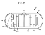
- FIG. 2 is a schematic diagram of the configuration of the capsule endoscope 10.
- the capsule endoscope 10 contains inside a capsule container 12 an imaging unit 110 which captures an intracelomic image to acquire image information, an illuminating unit 120 which emits illuminating light to an inside of a body cavity, and a transmission processing unit 140, a control unit 170, a power unit 180, and the like.
- the transmission processing unit 140 performs a process to wirelessly transmit the image information acquired by the imaging unit 110 via a transmission antenna 150.
- the power unit 180 supplies driving electricity for each unit of the capsule endoscope 10.
- the container 12 has a size which can be swallowed by a man or woman, and is formed with a substantially hemispherical front cover 13 and a body cover 14 forming a joint.
- the front cover 13 is made of a transparent material and works as an optical window.
- the imaging unit 110 and the illuminating unit 120 are arranged at positions opposing to the front cover 13 inside the container 12.
- the front cover 13 allows illuminating light from the illuminating unit 120 to transmit through the front cover 13 to an outside of the container 12, and introduces reflected light thereof to an inside of the container 12.
- illuminating light emitted by the illuminating unit 120 transmits through the front cover 13 to be reflected by a wall surface of organ. Then, the imaging unit 110 receives the reflected light via the front cover 13 and captures an image inside the subject 1.
- the image information acquired as above is broadly divided into those which are captured when the front cover 13 of the capsule endoscope 10 is close to an inner wall of organ, and those which are captured when the front cover 13 is away from the inner wall of organ.
- FIGS. 3-1 and 3-2 are explanatory diagrams of an example state of the capsule endoscope 10 where the capsule endoscope 10 is inside a cavity of a large intestine, and of an example of an acquired image, respectively.
- the capsule endoscope 10 is in a state where the front cover 13 is close to an intestine wall, and a captured image I10 covers only a small limited area of the intestine wall.
- the capsule endoscope 10 is in a state where the front cover 13 is away from an intestine wall and faces in a direction along the cavity, and with an captured image I20, an overview of the cavity can be observed broadly.
- the latter is useful, for example, for a screening test and the like.
- the image captured when the front cover 13 is close to the wall surface of intestine requires only a small amount of luminescence because the front cover 13 are close to the wall surface of intestine.
- the image captured when the front cover 13 faces in the direction along the cavity requires a large amount of luminescence because the front cover 13 is away from the wall surface of organ.
- distance between the front cover 13 and the wall surface of organ can be estimated based on information of the amount of luminescence of the acquired image, whereby a state of the capsule endoscope 10 can be classified to the state shown in FIG. 3-1 or the state shown in FIG. 3-2 .
- the present embodiment automatically divides the acquired image information as described above, and more specifically, divides the image information based on the amount of luminescence and the light-control amount information.
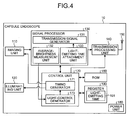
- FIG. 4 is a block diagram of a functional configuration of the capsule endoscope 10.
- the capsule endoscope 10 includes the imaging unit 110, the illuminating unit 120, a signal processor 130, the transmission processing unit 140, the transmission antenna 150, a ROM 160, a register 190, the control unit 170, the power unit 180.
- the imaging unit 110 includes an imaging device having an image sensor such as a CCD and CMOS, and an imaging lens which forms an image of incident light on the imaging device, and the like.
- the imaging unit 110 performs an imaging operation which outputs an analog signal corresponding to intensity of the incident light to capture an image inside the subject 1. To give a detailed description, the imaging unit 110 performs the imaging operation at a timing when an imaging-unit-driving pulse is supplied from a timing generator 171 which is described later.
- the illuminating unit 120 includes a light-emitting device such as a LED, and a driving circuit of the light-emitting device.
- the illuminating unit 120 performs an illuminating operation to emit illuminating light and to illuminate a portion imaged by the imaging unit 110.
- the illuminating unit 120 starts the illuminating operation at a timing when an illuminating-unit driving pulse is supplied from the timing generator 171, and emits illuminating light for a light-emitting time corresponding to a pulse duration of the supplied illuminating-unit driving pulse.
- the signal processor 130 includes a transmission-signal generator 131, an average-brightness measurement unit 132, and a light-emitting time attachment unit 133.
- the transmission-signal generator 131 performs an analog-signal process such as a color-balance adjustment and a gamma control on an analog signal which is input from the imaging unit 110, and then converts the analog signal into a digital signal. Based on the acquired digital signal, the transmission-signal generator 131 generates a transmission signal to be used for wirelessly transmitting the acquired image information to an outside. For example, with a frame representing information of a piece of image, the transmission-signal generator 131 attaches a vertical synchronizing signal to a head of the frame, and attaches a horizontal synchronizing signal to each head of constituent data of each line to thereby generate a transmission signal, and outputs the transmission signal to the transmission processing unit 140.
- an analog-signal process such as a color-balance adjustment and a gamma control on an analog signal which is input from the imaging unit 110, and then converts the analog signal into a digital signal.
- the transmission-signal generator 131 Based on the acquired digital signal, the transmission-signal generator
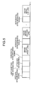
- FIG. 5 is a diagram of an example of a transmission signal generated by the transmission-signal generator 131.
- the transmission signal is formed as the vertical synchronizing signal, fields of light-emitting time and attached information, and constituent data of each line including the horizontal synchronizing signal.
- the light-emitting time information is input from the light-emitting time attachment unit 133 described later.
- the attached information is, for example, information such as a model or a serial number of the capsule endoscope, and white balance coefficient.
- the transmission signal is input into the transmission processing unit 140, and is wirelessly transmitted to the receiving apparatus 30 outside a body.
- the receiving apparatus 30 receiving the transmission signal detects a head part of an image via the vertical synchronizing signal, and a head of an image signal of each line via the horizontal synchronizing signal to thereby process each image signal and to acquire image information.
- the average-brightness measurement unit 132 measures an average brightness value of the acquired image information. Specifically, with a light-control area for a measurement previously set, the average-brightness measurement unit 132 calculates a weighted average value of RGB values of each pixel forming the light-control area, and acquires an average brightness of the light control area. The measured average brightness value is output to a light-control unit 173 described later. Alternatively, a whole area of the acquired image information may be measured to measure the average brightness value.
- Light-emitting time calculated by the light-control unit 173 described later is input to a register.
- the light-emitting time attachment unit 133 outputs the input light-emitting time to the transmission-signal generator 131 so that the light-emitting time is attached to the transmission signal generated by the transmission-signal generator 131.
- light-emitting time of the illuminating unit 120 on capturing is attached to the acquired image information.
- the transmission processing unit 140 is formed by a wireless-transmission circuit and the like which generate a wireless-transmission signal performing a modulation process and the like on the transmission signal input from the transmission signal generator 131 as needed.
- the transmission processing unit 140 performs a process to wirelessly transmit the generated transmission signal to an outside via the transmission antenna 150.
- the ROM 160 stores therein various data such as a serial number and a white balance coefficient needed for an operation of the capsule endoscope 10.
- the register 190 stores therein light-emitting time 191 calculated by the light-control unit 173 described later.
- a RAM may be used instead of the register 190.
- the control unit 170 controls each unit forming the capsule endoscope 10, and controls the entire operation of the capsule endoscope 10 extensively.
- the control unit 170 includes the timing generator 171 and the light-control unit 173.
- the timing generator 171 sets driving timing of the imaging unit 110 and the illuminating unit 120, and controls the imaging operation of the imaging unit 110 and the illuminating operation of the illuminating unit 120.
- an imaging-unit-driving pulse is supplied for the imaging unit 110 at intervals of 0.5 seconds to control the imaging operation of the imaging unit 110
- an illuminating-unit-driving pulse is supplied for the illuminating unit 120 just before the supply of the imaging start pulse to control the illuminating operation of the illuminating unit 120.
- the timing generator 171 increases or decreases a pulse amplitude of the illuminating-unit-driving pulse based on the light-emitting time which is input from the light-control unit 173, and determines a start timing of operation at a rising of the pulse and a termination timing of operation at a falling of the pulse. Then, the timing generator 171 drives each unit forming the signal processor 130 based on the timing of supply of the imaging-unit-driving pulse to thereby synchronize each process with the timing of supply of the imaging-unit-driving pulse.
- the light-control unit 173 determines light-control-amount information based on brightness of the image information acquired by the imaging unit 110, and performs a light-control control of the illuminating unit 120. Specifically, the light-control unit 173 compares an average value which is input from the average-brightness measurement unit 132 with a reference brightness value previously set as a reference brightness value, and determines the brightness of the light-control area of the acquired image information.
- the reference brightness value has for example, a brightness value with which a user can easily view a content of the image.
- the light-control unit 173 calculates, for example, light-emitting time of the illuminating unit 120 based on the comparison result as light-control information, and outputs the calculated light-emitting time to the timing generator 171.
- the light-emitting time of the illuminating unit 120 is calculated based on the brightness of the light-control area in the acquired image information, and in a following imaging operation, the illuminating unit 120 emits illuminating light according to the light-emitting time, whereby quality of captured images is stably maintained.
- the light-emitting time of the illuminating unit 120 is set short in the following operation, whereas when the brightness value of the captured image is smaller than the reference brightness value, the light-emitting time of the illuminating unit 120 is set long in the following operation.
- the light-control amount information is not limited to the light-emitting time.
- an electricity value supplied for a light-emitting device forming the illuminating unit 120 may be modulated as the light-control amount information.
- a gain of the output signal of an imaging device again may be modulated as the light-control amount information.
- light-emitting time calculated by the light-control unit 173 is output to the light-emitting time attachment unit 133 based on a supply timing of the following imaging-unit-driving pulse by the control unit 170. Then, the imaging unit 110 the image information acquired by the imaging unit 110 is wirelessly transmitted to the receiving apparatus 30 along with the light-emitting time of the illuminating unit 120 in the capturing.
- FIG. 6 is a block diagram of a functional configuration of the receiving apparatus 30.
- the receiving apparatus 30 includes antennas A1 to An, a receiving unit 310, a reference clock 320, a converter 330, a synchronizing-signal detection unit 340, an image processing unit 350, a display unit 360, a storage unit 370, a read-write unit 380, a control unit 390, and a power supply unit 400.
- the power supply unit 400 supplies driving electricity for each unit forming the receiving apparatus 30.
- the receiving unit 310 receives a wireless-transmission signal from the capsule endoscope 10 via receiving antennas A1 to An. Specifically, the receiving unit 310, under a control by the control unit 390, switches a receiving antenna to receive the wireless-transmission signal from the capsule endoscope, to any of the receiving antennas A1 to An. More specifically, the switching of the receiving antennas is performed as each of the receiving antennas A1 to An detects a reception intensity of the wireless-transmission signal from the capsule endoscope 10, and the control unit 390 performs a control to switch a receiving antenna to a receiving antenna with the highest reception intensity of wireless transmission signals.
- the receiving unit 310 performs a demodulation process on a wireless-transmission signal from the capsule endoscope 10 via the switched receiving antenna to thereby demodulate the wireless-transmission signal to be an image signal.
- the image signal corresponds to the transmission signal generated by the capsule endoscope 10.
- the image signal includes the image information acquired by the capsule endoscope 10, a vertical synchronizing signal contained in each frame, a horizontal synchronizing signal contained in each line of a frame, light-emitting time information, and attached information.
- the reference clock 320 outputs a clock signal which works as a reference of a process performed on a wireless-transmission signal from the capsule endoscope 10.
- the converter 330 performs a serial/parallel conversion process on the image signal demodulated by the receiving unit 310.
- the synchronizing-signal detection unit 340 detects the vertical synchronizing signal contained in the demodulated image signal for each frame, and instructs a timing of an image processing of the image processing unit 350.
- the image processing unit 350 performs a predetermined image processing on the demodulated image signal, processes the image signal to a desired format, and outputs the same to the control unit 390.
- the display unit 360 displays an image received by the capsule endoscope 10, a name of patient, and the like on screen, and is realized, for example, by a small LCD, a small ELD, or the like.
- the storage unit 370 is realized by a variety of IC memories such as a ROM and a RAM of re-writable flash memories or the like.
- the storage unit 370 stores therein a program for operations of the receiving apparatus 30, programs for realizing various functions of the receiving apparatus 30, data for processing the programs, and the like.
- the portable storage medium 50 is detachably arranged.
- the read-write unit 380 sequentially stores image information on which the image processing has been performed by the image processing unit 350.
- the read-write unit 380 is realized by a read-write apparatus suitable for a type of the portable storage medium 50.
- the control unit 390 sends instructions for each unit forming the receiving apparatus 30, and performs data transfer, and the like based on the program, data and the like stored in the storage unit 370, and broadly controls the overall operations of the receiving apparatus 30.
- the control unit 390 includes a light-emitting time detection unit 391.
- the light-emitting time detection unit 391 detects, based on the light-emitting time information received along with the image information processed by the image processing unit 350, light-emitting time of the illuminating unit 120 at the time of capturing of image information.
- the control unit 390 displays the image information, which is received by the receiving unit 310 and is processed by the image processing unit 350, on the display unit 360, and performs a process to switch and continuously display the image information in order of reception. Then, along with the displaying, the control unit 390 determines display/nondisplay of the image information based on the light-emitting time detected by the light-emitting time detection unit 391. For example, the determination is performed based on whether the detected light-emitting time is longer than reference light-emitting time previously set as a threshold value. As shown in FIG.
- the reference light-emitting time is previously set at a value to determine whether the image is one captured when the front cover 13 of the capsule endoscope 10 is close to the wall surface of organ such as a intestine wall as shown in FIG. 3-1 , or whether the image is one captured when the front cover 13 is away from the wall surface of organ as shown in FIG. 3-2 .
- the control unit 390 performs a process to display the image information on screen of the display unit 360.
- control unit 390 may perform a control to fast-forward and change the display time depending on when the light-emitting time of the image information at the time of capturing is longer than the reference light-emitting time, or, equal to or shorter than the reference light-emitting time. For example, when the light-emitting time of the image information at the time of capturing is longer than the reference light-emitting time, the display time of the image information is set longer than a case when the light-emitting time of the image information at the time of capturing is equal to or shorter than the reference light-emitting time. Thus, the control unit 390 performs a process to display the image information to be displayed on screen for display time corresponding to the light-emitting time at the time of acquisition.
- control unit 390 controls the read-write unit 380 to sequentially stores in the portable storage medium 50 image information processed by the image processing unit 350 in correspondence with the light-emitting time information received along with the image information.
- the control unit 390 may be configured to store only the image information whose light-emitting time at the time of capturing is longer than the reference light-emitting time, and not the image information whose light-emitting time at the time of capturing is equal to or shorter than the reference light-emitting time.
- the image information stored in the portable storage medium 50 is read by the display apparatus 70, and displayed on screen of a display. Further, when the display apparatus 70 displays the image information on screen, processes may be performed similarly to the processes according to the screen display of the image information by the receiving apparatus 30.
- the display/nondisplay of the image information is determined based on the light-emitting time information stored in the portable storage medium 50 in correspondence with the image information to be displayed. Specifically, the determination is performed based on whether the detected light-emitting time is longer than the reference light-emitting time which is previously set as the threshold value. Further, when the image information is determined to be displayed, the process of the screen display is performed via the display.
- FIG. 7 is an operational flowchart of the capsule endoscope 10 according to the transmission of the acquired image information.
- the imaging unit 110 captures an inside of the subject 1 (Step S11).
- the transmission-signal generator 131 generates a transmission signal based on the acquired image information.
- the light-emitting time attachment unit 133 reads the light-emitting time 191 stored in the register 190 via the control unit 170 (Step S13), and attaches the light-emitting time 191 to the transmission signal to thereby attach the light-emitting time of the illuminating unit 120 at the time of capturing to the acquired image information (Step S15). Then, the transmission processing unit 140 performs a process to wirelessly transmit the transmission signal input from the transmission-signal generator 131 to an outside of a body (Step S17).
- FIG. 8 is an operational flowchart of the receiving apparatus 30 according to the screen display of the acquired image information.
- the receiving unit 310 receives the wireless-transmission signal from the capsule endoscope 10 (Step S21).
- the wireless-transmission signal is demodulated to an image signal by the receiving unit 310.
- the light-emitting time detection unit 391 identifies light-emitting time information contained in the image signal, and detects the light-emitting time of the illuminating unit 120 at the time of capturing (Step S23).
- the control unit 390 compares the light-emitting time detected by the light-emitting time detection unit 391 to the reference light-emitting time.
- Step S25: Yes If the detected light-emitting time is longer than the reference light-emitting time as a result of the comparison (Step S25: Yes), the control unit 390 performs a process to display the image information on a screen of the display unit 360 (Step S27). On the other hand, if the detected light-emitting time is equal to or shorter than the reference light-emitting time (Step S25: No), the control unit 390 proceeds to Step S29. At Step S29, until the control unit 390 finishes receiving the image information (Step S29: No), the control unit 390 returns to Step S21 and repeats the processes above. Thus, the control unit 390 sequentially displays image information which is wirelessly transmitted from the capsule endoscope 10, and whose light-emitting time at the time of capturing is longer than the reference light-emitting time, on the screen of the display unit 360.
- the capsule endoscope 10 can acquire the light-emitting time of the illuminating unit 120 at the time of capturing as information from which distance between a head part of the front cover 13 and the wall surface of organ to be captured can be estimated. Further, the light-emitting time information can be attached to the image information and wirelessly transmitted to the receiving apparatus 30. data and the like stored in the storage unit 370. On the other hand, the receiving apparatus 30 compares the light-emitting time at the time of capturing to the reference light-emitting time.
- the received image information can be divided to those which are captured when the head of the front cover 13 of the capsule endoscope 10 is close to the wall surface of organ such as an intestine wall, and those which are captured when the head of the front cover 13 away from the wall surface of organ. Then, based on the result of division, only the image information captured when the front cover 13 is close to the wall surface of organ can be displayed on screen. Therefore, the image information which needs to be checked for a screening test and the like can be automatically extracted, whereby the observer can shorten observation time, and avoid burden on visually dividing the image information.
- FIG. 9 is an explanatory diagram of a example control of the display/nondisplay of the image information.
- the light-emitting time at the time of capturing is determined to longer than the reference light-emitting time in frames 4 and 5, and the image information of the frames 4 and 5 is displayed on screen.
- the frames 1 to 3 the light-emitting time at the time of capturing is determined to be shorter than reference light-emitting time. Image information of the frames 1 and 2 are not displayed while image information of the frame 3 is displayed considering the convergence time.
- distance between the head part of the front cover 13 of the capsule endoscope 10 and the wall surface of organ may be calculated based on the light-emitting time at the time of capturing.
- the image information may be divided based on this calculated estimated distance.
- the receiving apparatus 30 may display the calculated estimated distance on screen along with the received image information.
- distance between the head part of the front cover 13 and the wall surface of organ may be calculated inside the capsule endoscope 10, or may be calculated inside the receiving apparatus 30.
- the transmission signal including information of the calculated estimated distance is wirelessly transmitted to the receiving apparatus 30.
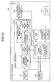
- FIG. 10 is a block diagram of a functional configuration of a capsule endoscope 10b according to the second embodiment. Same numerals are attached to components which are identical to the components of the first embodiment.
- the capsule endoscope 10b includes a signal processor 130b which is formed by a transmission-signal generator 131b, an average-brightness measurement unit 132, a light-emitting time comparison unit 134, and a transmission determination unit 135, a light-emitting time attachment unit 133b.
- the transmission-signal generator 131b generates a transmission signal to wirelessly transmit the image information which is determined to be transmitted by the transmission determination unit 135 described later of the acquired image information to an outside of body.
- the transmission-signal generator 131b attaches light-emitting time input by the light-emitting time attachment unit 133b to the generated transmission signal.
- the transmission signal is wirelessly transmitted to the outside of body by the transmission processing unit 140, whereby the acquired image information is wirelessly transmitted to the receiving apparatus 30.
- the transmission-signal generator 131b does not generate a transmission signal for the image information which is determined not to be transmitted by the transmission determination unit 135.
- light-emitting time comparison unit 134 For the light-emitting time comparison unit 134, light-emitting time 191 is input into a register 190 via a control unit 170. The light-emitting time comparison unit 134 compares the input light-emitting time to the reference light-emitting time, and outputs the comparison result to the transmission determination unit 135.
- the transmission determination unit 135 determines, based on the comparison result input by the light-emitting time comparison unit 134, whether the image information is to be transmitted. Specifically, the transmission determination unit 135 determines that the image information is to be transmitted when the light-emitting time of the illuminating unit 120 at the time of capturing is longer than the reference light-emitting time as a result of the comparison by the light-emitting time comparison unit 134. On the other hand, the transmission determination unit 135 determines that the image information is not to be transmitted when the light-emitting time of the illuminating unit 120 at the time of capturing is equal to or shorter than the reference light-emitting time. The determination result is output to the transmission-signal generator 131b and the light-emitting time attachment unit 133b.
- the light-emitting time 191 stored in the register 190 via the control unit 170 is input into the light-emitting time attachment unit 133b.
- the light-emitting time attachment unit 133b outputs the light-emitting time to the transmission-signal generator 131b.
- the transmission-signal generator 131b attaches the light-emitting time to the transmission signal.
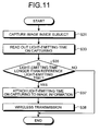
- FIG. 11 is an operational flowchart of the capsule endoscope 10b according to the transmission of the acquired image information.
- the imaging unit 110 captures an inside of the subject 1 (Step S31).
- the light-emitting time comparison unit 134 reads out the light-emitting time 191 stored in the register 190 via the control unit 170 (Step S33).
- the light-emitting time comparison unit 134 compares the light-emitting time of the illuminating unit 120 at the time of capturing to the reference light-emitting time.
- the transmission determination unit 135 determines, based on the comparison result, whether the image information is to be transmitted.
- the transmission signal generator 131b generates a transmission signal based on the acquired image information.
- the light-emitting time attachment unit 133b attaches the light-emitting time to the transmission signal to thereby attach the light-emitting time of the illuminating unit 120 at the time of capturing to the acquired image information (Step S38).
- the process is finished.
- the capsule endoscope 10b acquires the light-emitting time of the illuminating unit 120 at the time of capturing as information from which the distance between the head part of the front cover 13 and the wall surface of organ can be estimated. Further, the light-emitting time at the time of capturing is compared to the reference light-emitting time.
- the acquired image information can be divided to those which are captured when the head part of the front cover 13 is close to the wall surface of organ, and those which are captured when the head part of the front cover 13 is away from the wall surface of organ. Based on the result of division, only the image information captured when the head part is close to the wall surface of organ can be transmitted to the outside of body.
- the image information which needs to be checked for a screening test or the like can be automatically extracted, whereby the observer can shorten observation time, and avoid burden on visually dividing the image information. Further, since only images which need to be checked are transmitted, power consumption of the capsule endoscope 10b can be reduced.
- the transmission determination unit 135 of the signal processor 130b determines whether the image acquired image information is to be transmitted, and generates, based on the result of determination, the transmission signal.
- the transmission signal 130b may generate the transmission signal regardless of the light-emitting time at the time of capturing and determine whether the transmission signal is to be transmitted. Further, the determination as to whether the image information is to be transmitted may be performed considering convergence time of the light-control control.
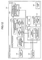
- FIG. 12 is a block diagram explaining a functional configuration of a capsule endoscope 10c according to the present variation. Same numerals are attached to components which are identical with the components of the second embodiment.
- the capsule endoscope 10c includes a signal processor 130 formed by a transmission-signal generator 131c, an average-brightness measurement unit 132, a light-emitting time comparison unit 134c, and a light-emitting time attachment unit 133c.
- the transmission-signal generator 131c generates a transmission signal to wirelessly transmit the acquired image information to the outside of body, and attaches the light-emitting time information which is input from the light-emitting time attachment unit 133c to the generated signal.
- the transmission signal is output to the transmission processing unit 140c.
- the light-emitting time 191 stored in the register 190 via the control unit 170 is input into the light-emitting time comparison unit 134c.
- the light-emitting time comparison unit 134c compares the input light-emitting time to the reference emitting time. The comparison result is output to the control unit 170. Further, the light-emitting time attachment unit 133c outputs the light-emitting time to the transmission-signal generator 131c, and attaches the light-emitting time to the transmission signal generated by the transmission-signal generator 131c.
- the transmission processing unit 140c includes a transmission determination unit 141.
- the transmission determination unit 141 under a control by the control unit 170, determines whether the transmission signal input from the transmission-signal generator 131c is to be transmitted. Then, the transmission processing unit 140c generates a wireless-transmission signal based on the transmission signal which is determined to be transmitted by the transmission determination unit 141, and performs a process to wirelessly transmit the generated wireless-transmission signal to an outside via a transmission antenna 150.
- control unit 170 controls the operation of the transmission determination unit 141 based on the comparison result input from the light-emitting time comparison unit 134c. Specifically, the control unit 170 controls the transmission determination unit 141 to determine that the transmission signal input from the transmission-signal generator 131c is to be transmitted when the light-emitting time of the illuminating unit 120 at the time of capturing is longer than the reference light-emitting time as the result of comparison by the light-emitting time comparison unit 134c.
- control unit 170 controls the transmission determination unit 141 to determine that the transmission signal input from the transmission-signal generator 131c is not to be transmitted when the light-emitting time of the illuminating unit 120 at the time of capturing is equal to or shorter than the reference light-emitting time.
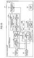
- FIG. 13 is a block diagram of a functional configuration of a capsule endoscope 10d according to the third embodiment. Same numerals are attached to components which are identical with the components of the first embodiment.
- the capsule endoscope 10d includes a signal processor 130d formed by a transmission-signal generator 131d, an average-brightness measurement unit 132, a light-emitting time comparison unit 134d, a light-emitting time attachment unit 133d, a data-compression determination unit 136.
- the transmission-signal generator 131d generates a transmission signal to wirelessly transmit the acquired image information to the outside of body, and attaches the light-emitting time information input from the light-emitting time attachment unit 133d to the generated transmission signal. Further, when the image information is determined to be compressed by the data-compression determination unit 136 as described later, the transmission-signal generator 131d performs a compression process on the image information. For the encoding, an irreversible compression such as JPEG is adopted for example. Alternatively, a reversible method may be adopted. The transmission signal is output to the transmission processing unit 140.
- the light-emitting time 191 stored in the register 190 via the control unit 170 is input into the light-emitting time comparison unit 134d.
- the light-emitting time comparison unit 134d compares the input light-emitting time to the reference light-emitting time.
- the light-emitting time attachment unit 133d outputs the light-emitting time to the transmission-signal generator 131d so as to attach the light-emitting time to the transmission signal generated by the transmission-signal generator 131d.
- the data-compression determination unit 136 determines whether the image information is to be compressed based on the comparison result by the light-emitting time comparison unit 134d. Specifically, the data-compression determination unit 136 determines that the image information is not to be compressed when the light-emitting time of the illuminating unit 120 at the time of capturing is longer than the reference light-emitting time as the result of comparison by the light-emitting time comparison unit 134d. On the other hand, the data-compression determination unit 136 determines that the image information is to be compressed when the light-emitting time of the illuminating unit 120 at the time of capturing is equal to or shorter than the reference light-emitting time. The result of determination is output to the transmission-signal generator 131d.
- FIG. 14 is an operational flowchart of the capsule endoscope 10d according to the transmission of the acquired image information.
- the imaging unit 110 captures an inside of the subject 1 (Step S401).
- the transmission-signal generator 131d generates a transmission signal based on the image information acquired by the imaging unit 110 while the light-emitting time comparison unit 134d reads out the light-emitting time 191 stored in the register 190 via the control unit 170 (Step S403).
- the light-emitting time comparison unit 134d compares the light-emitting time of the illuminating unit 120 at the time of capturing to the reference light-emitting time.
- the data-compression determination unit 136 determines, based on the result of comparison, whether the image information is to be compressed. Specifically, if the light-emitting time is longer than the reference light-emitting time (Step S405: Yes), the control unit 170 proceeds to Step S409. On the other hand, if the light-emitting time is equal to or shorter than the reference light-emitting time (Step S405: No), the data-compression determination unit determines that the image information is to be compressed, and outputs the result of determination to the transmission-signal generator 131d.
- the transmission-signal generator 131d compresses the image information (Step S407). Further, the light-emitting time attachment unit 133d attaches the light-emitting time to the transmission signal to thereby attach the light-emitting time of the illuminating unit 120 to the acquired image information (Step S409). Then, the transmission processing unit 140 performs a process to wirelessly transmit the transmission signal input from the transmission-signal generator 131d to the outside of body (Step S411).
- the capsule endoscope 10d can acquire the light-emitting time of the illuminating unit 120 at the time of capturing as information from which the distance between the head part of the front cover 13 and the wall surface of organ can be estimated. Further, the capsule endoscope 10d compares the light-emitting time at the time of capturing to the reference light-emitting time.
- the acquired image information can be divided to those which are captured when the head part of the front cover 13 is close to the wall surface of organ, and those which are captured when the head part of the front cover 13 is away from the wall surface of organ. Based on the result of division, only the image information captured when the head part is close to the wall surface of organ can be compressed.
- the irreversible compression method is adopted for the encoding, the image information on which the compression process has been performed deteriorates after the encoding, meanwhile a compression rate higher than that of the reversible encoding can be achieved. Therefore, the operation time of the transmission processing unit 140 according to the transmission of the image information can be shortened and power consumption can be reduced.
- the determination as to whether the image information is to be compressed is performed based on the light-emitting time at the time of capturing. Further, curtailing operation or a clipping operation may be performed on the image information whose light-emitting time at the time of capturing is equal to or shorter than the reference light-emitting time. Further, the determination as to whether the compression is to be performed or whether the curtailing operation or the clipping operation to be performed may be performed considering the convergence time of the light-control control.
- FIG. 15 is a block diagram explaining a functional configuration of a capsule endoscope 10e according to the fourth embodiment. Same numerals are attached to components which are identical with the components of the first embodiment.
- the capsule endoscope 10e includes a signal processor 130e formed by a transmission-signal generator 131e, an average-brightness measurement unit 132, a light-emitting time comparison unit 134e, a light-emitting time attachment unit 133e, a data-compression-rate setting unit 137.
- the transmission-signal generator 131e generates a transmission signal to wirelessly transmit the acquired image information to the outside of body, and attaches the light-emitting time information input from the light-emitting time attachment unit 133e to the generated transmission signal. Further, the transmission-signal generator 131e performs a compression process on the image information according to the compression rate set by the data-compression-rage setting unit 137 as described later.
- the data-compression-rate setting unit 137 sets a compression rate based on the result of comparison by the light-emitting time comparison unit 134e. Specifically, the data-compression-rate setting unit 137 sets the compression rate at a predetermined value X and outputs the same to the transmission-signal generator 131e when the light-emitting time of the illuminating unit 120 at the time of capturing is longer than the reference light-emitting time as the result of comparison by the light-emitting time comparison unit 134e.
- the data-compression-rate setting unit 137 sets the compression rate at a predetermined value Y (Y > X) and outputs the same to the transmission-signal generator 131e when the light-emitting time of the illuminating unit 120 at the time of capturing is equal to or shorter than the reference light-emitting time.
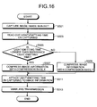
- FIG. 16 is an operational flowchart of the capsule endoscope 10d according to the transmission of the acquired image information.
- the imaging unit 110 captures the inside of subject 1 (Step S501).
- the transmission-signal generator 131e generates the transmission signal based on the image information acquired by the imaging unit 110 while the light-emitting time comparison unit 134e reads out the light-emitting time 191 from the register 190 via the control unit 170 (Step S503).
- the light-emitting time comparison unit 134e compares the light-emitting time of the illuminating unit 120 at the time of capturing to the reference light-emitting time, and the data-compression-rate setting unit 137 sets the compression rate of the image information based on the result of comparison. Specifically, if the light-emitting time is longer than the reference light-emitting time (Step S505: Yes), the data-compression-rate setting unit 137 outputs the compression rate X to the transmission-signal generator 131e. Accordingly, the transmission-signal generator 131e compresses the image information by the compression rate X (Step S507).
- the light-emitting time is equal to or shorter than the reference light-emitting time (Step S505: Yes)
- the data-compression-rate setting unit 137 outputs the compression rate Y to the transmission-signal generator 131e.
- the transmission-signal generator 131e compresses the image information by the compression rate Y (>X) (Step S509).
- the light-emitting time attachment unit 133e attaches the light-emitting time to the transmission signal to thereby attach the light-emitting time of the illuminating unit 120 at the time of capturing to the acquired image information (Step S511).
- the transmission unit 140 performs a process to wirelessly transmit the transmission signal input from the transmission-signal generator 131e to the outside of body (Step S513).
- the capsule endoscope 10e can acquire the light-emitting time of the illuminating unit 120 at the time of capturing as information from which distance between the head part of the front cover 13 and the wall surface of organ can be estimated. Further, the capsule endoscope 10d compares the light-emitting time at the time of capturing to the reference light-emitting time so that the acquired image information can be divided into those which are captured when the head part of the front cover 13 is close to the wall surface of organ, and those which are captured when the head part of the front cover 13 is away from the wall surface of organ.
- the compression process is performed on the acquired image information, and the compression rate for the compression is set based on the light-emitting time at the time of capturing.
- the curtailing process may be performed on the acquired image information.
- the curtailment rate for curtailing may be set based on the light-emitting time at the time of capturing.
- the capsule endoscope is described to have the configuration including a pair of the imaging unit and the illuminating unit. Further, the capsule endoscope having a configuration including two or more pairs of the imaging unit and the illuminating unit may be applied similarly.
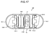
- FIG. 17 is a schematic configuration diagram of a capsule endoscope 10f including two pairs of the imaging unit and the illuminating unit.
- FIG. 18 is a block diagram of a functional configuration of the capsule endoscope 10f. Same numerals are attached to components which are identical with the components of the first embodiment.
- the capsule endoscope 10f employs the imaging unit and the illuminating unit on both head parts thereof so that the capsule endoscope 10f can capture the image information both in front and in back inside the subject 1.
- the capsule endoscope 10f contains inside a capsule container 15 a front-imaging unit 110-1 and a back-imaging unit 110-2, a front-illuminating unit 120-1 and a back-illuminating unit 120-2, a signal processor 130f, a transmission processing unit 140, a transmission antenna 150, a ROM 160, a register 190, a control unit 170f, a power unit 180, and the like.
- the container 15 is formed with substantially hemispherical front covers 16-1, 16-2, a cylindrical body cover 17 forming a joint.
- the front covers 16-1, 16-2 are made of a transparent material, and work as optical windows.
- the front cover 16-1 allows illuminating light from the front-illuminating unit 120-1, which is arranged at an opposing position to the front cover 16-1 inside the container 15, to transmit through the front cover 16-1 to an outside of the container 15, and introduces reflected light thereof to an inside of the container 15.
- the front cover 16-2 allows illuminating light from the back-illuminating unit 120-2, which is arranged at an opposing position to the front cover 16-1 inside the container 15, to transmit through the front cover 16-1 to an outside of the container 15, and introduces reflected light thereof to an inside of the container 15.
- the front-imaging unit 110-1 and the back-imaging unit 110-2 perform, under a control by a timing generator 171f, imaging operations at the same timing. Further, the front-imaging unit 110-1 and the back-imaging unit 110-2 perform, under a control by the timing generator 171f, illuminating operations at the same timing.
- a light-control unit 173f determines a light-control amount based on brightness of the image information acquired last time by the imaging units 110-1, 110-2, and performs a light-control control of the illuminating units 120-1, 120-2.
- the transmission-signal generator 131f In the signal processor 130f of the capsule endoscope 10f, the transmission-signal generator 131f generates a transmission signal to wirelessly transmit the acquired image information to the outside of body.
- the transmission-signal generator 131f attaches imaging-unit-identification information indicating which has captured the acquired image information, an imaging operation of the imaging unit 110-1 or 110-2, to the acquired image information. Further, similarly to the first embodiment, the transmission-signal generator 131f attaches the information of light-emitting time and attached information which are input from the light-emitting time attachment unit 133 to the acquired image information, to thereby generate the transmission signal.
- the generated transmission signal is transmitted by the transmission processing unit 140 to the receiving apparatus 30 arranged outside the body.
- FIG. 19 is an explanatory diagram showing an example state of the capsule endoscope 10f and an example of acquired image when the capsule endoscope 10f is in the cavity of large intestine.
- the capsule endoscope 10f is in a state where the front cover 16-1 is close to the intestine wall and others while the front cover 16-2 faces in a direction to the cavity side.
- an image 131 captured by the front-imaging unit 110-1 on a side of the front cover 16-1 covers only a small limited area of the intestine wall.
- an image I33 captured by the back-imaging unit 110-2 on a side of the front cover 16-2 broadly covers an overview of the cavity.
- the image I33 is useful.
- the receiving apparatus 30 which receives the image information wirelessly transmitted from the capsule endoscope 10f and the display apparatus 70 perform, for example, a process to display on screen, side-by-side, information of two images captured by the front-imaging unit 110-1 and the back-imaging unit 110-2 of the capsule endoscope 10f at the same timing. Then, for example, the light-emitting time at the time of capturing is compared to the reference light-emitting time.
- the image information at the time of capturing i.e., when it is determined that one of the image information is captured at a position away from the wall surface of organ (e.g., a case shown in FIG. 19 ), the information of the image and that of another image are displayed on screen side-by-side.
- both of the image information may be displayed on screen side-by-side only when the light-emitting time at the time of capturing is longer than the reference light-emitting time in both of the image information, i.e., when it is determined that both of the image information are captured at a position away from the wall surface of organ.
- both of pieces of the image information are not displayed.
- both of the image information may be transmitted.
- both of the image information may be transmitted when the light-emitting time in one of the image information at the time of capturing is longer than the reference light-emitting time.
- a compression rate may be determined, based on the light-emitting time at the time of capturing, for the image information acquired by the front-imaging unit 110-1 and the back-imaging unit 110-2, respectively.
- the capsule endoscope attaches the light-emitting time information to the image information and wirelessly transmits the image information to the receiving apparatus 30.
- the capsule endoscope may wirelessly transmit the image information without attaching the light-emitting time information to the image information.
- the light-emitting time at the time of capturing is compared to the reference light-emitting time. Then, the acquired image information is divided to those which are captured when the head part on the side of front cover of the capsule endoscope is close to the wall surface of organ, and those which are captured when the head part is away from the wall surface of organ.
- the image information may be divided to more groups, for example, by setting plural reference light-emitting times in stages. For example, by setting the reference light-emitting time in two stages, the image information can be divided to three groups based on the light-emitting time at the time of capturing.
- First group is the image information determined as being captured when the front cover is in close contact with the wall surface of organ because the head part on the side of front cover of the capsule endoscope is close to the wall surface of organ.
- Second one is the image information determined as being captured when the front cover is in a direction to the cavity because the head part on the side of front cover of the capsule endoscope is away from the wall surface of organ, i.e.,.
- Third one is the image information determined as being captured when the capsule endoscope faces in an oblique direction to the cavity because the head part on the side of front cover of the capsule endoscope is in middle distance from the wall surface of organ.
- the compression rate for the compression of the image information can be suitably adjusted depending on the group of the image information.
- FIGS. 20-1 and 20-2 are diagrams explaining a retriever 80 of a capsule medical apparatus according to the fifth embodiment and retrieval method therefor, and showing states inside the toilet bowl 100 as cross sections, respectively.
- the retriever 80 according to the fifth embodiment is used for retrieving the capsule medical apparatus which is discharged outside the body along with stool.
- the retriever 80 includes a water-soluble sheet 81 and a gripping member 83.
- FIG. 21 is a cross-sectional view showing schematically an internal configuration of the water-soluble sheet 81.
- the water-soluble sheet 81 has, for example, a double-layer structure where the two water-soluble sheets 811-1, 811-2 are stacked, and an air layer 813 is formed between each of the water-soluble sheets 811-1, 811-2. Accordingly, the water-soluble sheet 81 is more likely to float on the water surface of reserved water in the toilet bowl 100, whereby the retrieval of the capsule medical apparatus can be accurately performed.
- the water-soluble sheet 81 is made large enough to cover the entire wall surface of reserved water in the toilet bowl 100.
- a single-layer structure may be adopted.
- a multiple-layer structure where three or more water-soluble sheets are stacked and the air layer is formed between each of the water-soluble sheet may be adopted.
- the gripping member 83 is used for gripping the capsule medical apparatus discharged onto the water-soluble sheet 81 along with stool, and is realized, for example, by tweezers.
- FIG. 22 is a plan view of the gripping member 83.
- the head part 831 of the gripping member 83 has a cross section forming a curved surface so that the water-soluble sheet 81 is not likely to be torn.
- a non-skid treatment is performed on the head part 831 of the gripping member 83 so that the capsule medical apparatus can be easily gripped.
- the gripping member 83 is disposed after use. Therefore, it is preferable that the gripping member 83 is made of cheap plastic or a paper to be disposed after use.
- the method for retrieving the capsule medical apparatus with the retriever 80 is described.
- the water-soluble sheet 81 is arranged on the water surface of reserved water in the toilet bowl 100.
- the stool 111 discharged onto the water-soluble sheet 81 is broken using the gripping member 83 without tearing the water-soluble sheet 81, and the capsule medical apparatus is searched.
- the gripping member 83 sandwiches the stool from sides so that no force is caused in a direction substantially vertical to the water-surface of reserved water in the toilet bowl 100, and the stool is broken by gripping force acting in a direction substantially horizontal to the water-surface of reserved water in the toilet bowl 100, whereby the capsule medical apparatus is searched.
- the capsule medical apparatus 90 found from the broken stool 113 is gripped and retrieved by the gripping member 83. After the capsule medical apparatus 90 is retrieved, the water-soluble sheet 81 is discharged with the reserved water in the toilet bowl 100.
- FIG. 23 is a diagram showing an example of the storage bag 85.
- the storage bag 85 is a bag for storing the capsule medical apparatus 90 and the gripping member 83 which has gripped and retrieved the capsule medical apparatus 90.
- the storage bag 85 is made, for example, of nylon-laminated or polyethylene-laminated material, and is made opaque with aluminum deposited thereon like an aluminum-laminated zip-top bag.
- a zip 851 is formed on an upper opening of the storage bag 85 so that the capsule medical apparatus 90 and the gripping member 83 can be sealed and stored in the storage bag 85.
- a development of bad odor is prevented and the waste materials are kept obscure.
- plural storage bags may be prepared so that another storage bag can further store the storage bag, for example, in case an outer surface of the storage bag is tainted by the stool.
- the capsule medical apparatus 90 and the gripping member 83 may be separately stored in the storage bags and disposed.
- the capsule medical apparatus 90 since the stool is caught by the water-soluble sheet 81 arranged on the water surface of reserved water in the toilet bowl 100, the capsule medical apparatus 90 discharged onto the water-soluble sheet along with the stool can be searched and retrieved.
- a long rod-shaped retriever which can touch a bottom of the toilet bowl is needed for retrieving the capsule medical apparatus 90 from the stool.
- the capsule medical apparatus 90 can be searched as the stool is broken on the water-soluble sheet 81, whereby the retriever is no longer necessary to be made long. Further, since the stool is caught by the water-soluble sheet 81, the water-soluble sheet 81 can be discharged along with the reserved water in the toilet bowl 100 after the capsule medical apparatus 90 is retrieved.
- the gripping member 83 realized by tweezers sandwiches and grips the stool so that the stool on the water-soluble sheet 81 can be broken with no force acting on the water-soluble sheet 81, and the found capsule medical apparatus 90 can be gripped.
- the water-soluble sheet 81 is unlikely to be torn up and to sink down when the capsule medical apparatus 90 is retrieved, whereby the retrieval operation for the capsule medical apparatus 90 can be easily performed.
- the head part of the gripping member 83 forms a curved surface, whereby the water-soluble sheet 81 is further unlikely to be torn up when the stool is broken on the water-soluble sheet 81 and the capsule medical apparatus 90 is searched.
- a water-repellent treatment or a water-sprinkling treatment may be performed, at least, on a surface of the water-soluble sheet 81 which faces the water surface when the water-soluble sheet 81 is arranged on the surface of reserved water in the toilet bowl 100. Accordingly, time for the water-soluble sheet 81 to dissolve in the reserved water inside the toilet bowl 100 can be controlled, whereby the retrieval operation can be performed even more easily.
- FIG. 24 is a plan view of a gripping member 83b according to the present variation.
- the head part 831b of the gripping member 83b is formed flat so that the head part 831 is substantially parallel to a sheet surface of the water-soluble sheet when the stool is broken on the water-soluble sheet, and the capsule medical apparatus is gripped.
- the stool on the water-soluble sheet can be broken with no force acting on the water-soluble sheet, and the found capsule medical apparatus can be gripped and retrieved.
- FIG. 25 is a retriever 80c for the capsule medical apparatus according to the present variation.
- the retriever 80c may include a water-soluble sheet 81, and a gripping member 83c realized by tongs.
- the stool discharged onto the water-soluble sheet 81 is broken by the gripping member 83c realized by tongs, the found capsule medical apparatus 90 is gripped and retrieved by the gripping member 83c.
- a retriever for retrieving a capsule medical apparatus discharged outside a body with stool comprising:
- the water-soluble sheet is a stack of at least two sheets, where an air layer is formed between each of the sheets.
- a method for retrieving a capsule medical apparatus comprising:
- the method for retrieving the capsule medical apparatus according to Note 9, further comprising a storing step of storing at least one of the gripping member and the capsule medical apparatus gripped by the gripping member in a storage bag.
- an in-vivo image acquiring apparatus As described above, an in-vivo image acquiring apparatus, an in-vivo image receiving apparatus, and an in-vivo image acquiring system are useful for easily acquiring information from which the distance between the in-vivo image acquiring apparatus and the wall surface of organs which are the objects to be imaged can be estimated.
Landscapes
- Life Sciences & Earth Sciences (AREA)
- Health & Medical Sciences (AREA)
- Surgery (AREA)
- Engineering & Computer Science (AREA)
- Biophysics (AREA)
- Public Health (AREA)
- Veterinary Medicine (AREA)
- Physics & Mathematics (AREA)
- Pathology (AREA)
- General Health & Medical Sciences (AREA)
- Animal Behavior & Ethology (AREA)
- Biomedical Technology (AREA)
- Heart & Thoracic Surgery (AREA)
- Medical Informatics (AREA)
- Molecular Biology (AREA)
- Radiology & Medical Imaging (AREA)
- Optics & Photonics (AREA)
- Nuclear Medicine, Radiotherapy & Molecular Imaging (AREA)
- Computer Networks & Wireless Communication (AREA)
- Signal Processing (AREA)
- Endoscopes (AREA)
- Measurement Of The Respiration, Hearing Ability, Form, And Blood Characteristics Of Living Organisms (AREA)
Abstract
Description
- The present invention relates to an in-vivo image acquiring apparatus which is introduced inside a subject to acquire image information inside the subject, an in-vivo image receiving apparatus which receives the image information acquired by the in-vivo image acquiring apparatus, and an in-vivo image acquiring system using the in-vivo image acquiring apparatus.
- In recent years, a swallowable capsule endoscope has been proposed in a field of endoscope, where the capsule endoscope contains inside a capsule-shaped case an imaging unit which acquires image information inside a subject, an illuminating unit which illuminates a portion imaged by the imaging unit, a transmission unit which wirelessly transmits the image information inside the subject, and the like. The capsule endoscope is swallowed by the subject, i.e., a patient from a mouth and introduced inside the subject to examine the subject. The capsule endoscope moving with peristalsis picks up intracelomic images inside organs such as an esophagus, a stomach, a small intestine, and a large intestine until naturally excreted, and wirelessly transmits the acquired image information to an outside. Further, various technologies for the capsule endoscope have been disclosed. For example, there is a known technology where intensity and time of illumination is changed to be suitably adjusted for an amount of reflected light of illumination light emitted by the illuminating unit, whereby a dynamic range of an apparatus is expanded (Patent Document 1).
- Patent Document 1: Japanese Laid-open Patent Publication No.
2005-288191 - Such a capsule endoscope moves inside a body cavity while being close to and away from the wall surface of organ. Image information of a small area of the wall surface is obtained with the capsule endoscope being close to the wall surface of organ; image information of a large area of the wall surface is obtained with the capsule endoscope being away from the wall surface of organ. In the examination in which observation whether there is a lesion site or bleeding site is important, such as the screening test performed at the stage before complete examination, an image of a large area inside organ is more valuable than an image of a small limited area of the wall surface of organ. However, automatic extraction of such image information which needs to be checked requires to detect whether the capsule endoscope is in being close to the wall surface of organ or in being away from the wall surface of organ, and thus requires addition of components for measuring the distance between the capsule endoscope and the wall surface of organ. At present, an observer such as a doctor has to give a diagnosis while visually sorting, from a large amount of image information, image information which is valuable for examination and which needs to be checked, thereby resulting in a problem that needs a lot of time and effort.
- A problem other than the above problem is to find the best way of retrieving the capsule endoscope after being excreted out of the subject.
- The present invention is made in view of the above problems and an object of the present invention is to provide an in-vivo image acquiring apparatus, an in-vivo image receiving apparatus, and an in-vivo image acquiring system, which are capable of easily acquiring information from which the distance between the in-vivo image acquiring apparatus and the wall surface of organs which are the objects to be imaged can be estimated
- Another object of the present invention is to provide a retriever and a method of retrieving a capsule endoscope, which are capable of easily retrieving the capsule endoscope after being excreted out of the subject.
- To solve the problems described above and achieve the objects, an in-vivo image acquiring apparatus according to the present invention includes an imaging unit that is introduced inside a subject to acquire image information of the subject; an illuminating unit that illuminates an imaged portion imaged by the imaging unit; a transmission processing unit that performs a process to wirelessly transmit the image information acquired by the imaging unit to an external device; and a light-control unit that determines light-control amount information based on brightness of the image information acquired by the imaging unit to perform a light control of the illuminating unit using the light-control amount information. The transmission processing unit performs a process to wirelessly transmit the image information acquired by the imaging unit along with the light-control information used for the light control.
- An in-vivo image acquiring apparatus according to the present invention includes an imaging unit that is introduced inside a subject to acquire image information of the subject; an illuminating unit that illuminates an imaged portion imaged by the imaging unit; a transmission processing unit that performs a process to wirelessly transmit the image information acquired by the imaging unit to an external device; a light-control unit that determines light-control amount information based on brightness of the image information acquired by the imaging unit to perform a light control of the illuminating unit using the light-control amount information; and a transmission determination unit that determines, based on the light-control amount information used for the light control, whether the process to transmit the image information acquired by the imaging unit is to be performed. The transmission determination unit performs a process to wirelessly transmit the image information determined to be transmitted by the transmission determination unit.
- An in-vivo image acquiring apparatus according to the present invention includes an imaging unit that is introduced inside a subject to acquire image information of the subject; an illuminating unit that illuminates an imaged portion imaged by the imaging unit; a transmission processing unit that performs a process to wirelessly transmit the image information acquired by the imaging unit to an external device; a light-control unit that determines light-control amount information based on brightness of the image information acquired by the imaging unit to perform a light control of the illuminating unit; and an image processing unit that performs, based on the light-control amount information used for the light control, a predetermined image processing on the image information acquired by the imaging unit.
- In the in-vivo image acquiring apparatus according to the present invention, the image processing unit determines, based on the light-control amount information, whether the image information is to be compressed, and performs a compression process on the image information which is determined to be compressed.
- In the in-vivo image acquiring apparatus according to the present invention, the image processing unit sets a compression rate based on the light-control amount information, and performs the compression process on the image information according to the set compression rate.
- An in-vivo image receiving apparatus according to the present invention is for receiving image information transmitted wirelessly from the in-vivo image acquiring apparatus described above, and includes a receiving unit that is arranged outside the subject, and receives the image information and the light-control information transmitted wirelessly from the in-vivo image acquiring apparatus; and a display processing unit that performs, based on the light-control amount information received along with the image information by the receiving unit, a process to display the image information.
- An in-vivo image receiving apparatus according to the present invention is for receiving image information transmitted wirelessly from the in-vivo image acquiring apparatus describe above, and includes a receiving unit that is arranged outside the subject, and receives the image information and the light-control information transmitted wirelessly from the in-vivo image acquiring apparatus; and a display processing unit that performs, based on the light-control amount information received along with the image information by the receiving unit, a process to display the image information.
- An in-vivo image receiving apparatus according to the present invention is for receiving image information transmitted wirelessly from the in-vivo image acquiring apparatus described above, and includes a receiving unit that is arranged outside the subject, and receives the image information and the light-control information transmitted wirelessly from the in-vivo image acquiring apparatus; and a display processing unit that performs, based on the light-control amount information received along with the image information by the receiving unit, a process to display the image information.
- In the in-vivo image receiving apparatus according to the present invention, the display processing unit determines, based on the light-control amount information received along with the image information received by the receiving unit, whether the image information is to be displayed, and performs a process to display the image information which is determined to be displayed.
- In the in-vivo image receiving apparatus according to the present invention, the display processing unit performs a process to sequentially switch and continuously display the image information received by the receiving unit, and changes, based on the light-control amount information received along with the image information, display time of the image information.
- An in-vivo image acquiring system according to the present invention includes the in-vivo image acquiring apparatus described above; a receiving unit that is arranged outside the subject, and receives the image information and the light-control information transmitted wirelessly from the in-vivo image acquiring apparatus; and a display processing unit that performs, based on the light-control amount information received along with the image information by the receiving unit, a process to display the image information.
- An in-vivo image acquiring system according to the present invention includes the in-vivo image acquiring apparatus described above; a receiving unit that is arranged outside the subject, and receives the image information and the light-control information transmitted wirelessly from the in-vivo image acquiring apparatus; and a display processing unit that performs, based on the light-control amount information received along with the image information by the receiving unit, a process to display the image information.
- An in-vivo image acquiring system according to the present invention includes the in-vivo image acquiring apparatus described above; a receiving unit that is arranged outside the subject, and receives the image information and the light-control information transmitted wirelessly from the in-vivo image acquiring apparatus; and a display processing unit that performs, based on the light-control amount information received along with the image information by the receiving unit, a process to display the image information.
- According to the present invention, the light-control information for a control of light-control determined based on the brightness of the acquired image information can be easily acquired as information from which the distance between the in-vivo image acquiring apparatus and the wall surface of organs which are the subjects for the image information to be acquired by the in-vivo image acquiring apparatus can be estimated. Then, the light-control amount information can be wirelessly transmitted along with the image information acquired by the imaging unit. Accordingly, for example, an external apparatus can divide, based on the light-control amount information, the acquired image information to those which are captured when the in-vivo image acquiring apparatus is close to the wall surface of organ, and those which are captured when the in-vivo image acquiring apparatus is away from the wall surface of organ. Based on the result of division, a control can be realized, for example, where only the image information captured at a position close to the wall surface of organ is displayed, and the image information captured at a position away from the wall surface of organ is not displayed. Therefore, the image information which needs to be checked for the screening test and the like can be automatically extracted, whereby the observer can shorten observation time, and save burden on visually dividing the image information.
-
-
FIG. 1 is a schematic diagram of an overall configuration of an in-vivo image acquiring system according to a first embodiment. -
FIG. 2 is a schematic diagram of a configuration of a capsule endoscope according to the first embodiment. -
FIG. 3-1 is an explanatory diagram of an example of an acquired image, and an example of a state of a capsule endoscope. -
FIG. 3-2 is an explanatory diagram of an example of an acquired image, and an example state of the capsule endoscope. -
FIG. 4 is a block diagram of a functional configuration of the capsule endoscope according to the first embodiment. -
FIG. 5 is a diagram of an example of a transmission signal generated by a transmission-signal generator. -
FIG. 6 is a block diagram of a functional configuration of a receiving apparatus according to the first embodiment. -
FIG. 7 is a process flowchart of the capsule endoscope according to the first embodiment. -
FIG. 8 is a process flowchart of the receiving apparatus according to the first embodiment. -
FIG. 9 is an explanatory diagram of an example control of display/nondisplay of image information according to a variation. -
FIG. 10 is a block diagram for explaining a functional configuration of a capsule endoscope according to a second embodiment. -
FIG. 11 is a process flowchart of the capsule endoscope according to the second embodiment. -
FIG. 12 is a block diagram explaining a functional configuration of a capsule endoscope according to a variation. -
FIG. 13 is a block diagram explaining a functional configuration of a capsule endoscope according to a third embodiment. -
FIG. 14 is a process flowchart of the capsule endoscope according to the third embodiment. -
FIG. 15 is a block diagram explaining a functional configuration of a capsule endoscope according to a fourth embodiment. -
FIG. 16 is a process flowchart of the capsule endoscope according to the fourth embodiment. -
FIG. 17 is a schematic diagram of a configuration of the capsule endoscope according to the variation. -
FIG. 18 is a block diagram of a functional configuration of the capsule endoscope according to a variation. -
FIG. 19 is an explanatory diagram showing an example state of the capsule endoscope, and an example of an acquired image according to a variation. -
FIG. 20-1 is an explanatory diagram of a retriever for a capsule endoscope and a retrieval method thereof according to a fifth embodiment. -
FIG. 20-2 is an explanatory diagram of the retriever for the capsule endoscope and the retrieval method thereof according to the fifth embodiment. -
FIG. 21 is a cross-sectional view showing schematically an internal configuration of a water-soluble sheet. -
FIG. 22 is a plan view of a gripping member. -
FIG. 23 is a diagram of an example of a storage bag; -
FIG. 24 is a plan view of a gripping member according to a variation. -
FIG. 25 is a diagram of a retriever for a capsule endoscope according to a variation. -
- 10
- Capsule endoscope
- 110
- Imaging unit
- 120
- Illuminating unit
- 130
- Signal processor
- 131
- Transmission-signal generator
- 132
- Average-brightness measurement unit
- 133
- Light-emitting time attachment unit
- 140
- Transmission processing unit
- 150
- Transmission antenna
- 160
- ROM
- 190
- Register
- 191
- Light-emitting time
- 170
- Control unit
- 171
- Timing generator
- 173
- Light-control unit
- 180
- Power unit
- 30
- Receiving apparatus
- A1
- to An Receiving antennas
- 310
- Receiving unit
- 320
- Reference clock
- 330
- Converter
- 340
- Synchronizing-signal detection unit
- 350
- Image processing unit
- 360
- Display unit
- 370
- Storage unit
- 380
- Read-write unit
- 390
- Control unit
- 391
- Light-emitting time detection unit
- 400
- Power supply unit
- 50
- Portable storage medium
- 70
- Display apparatus
- 1
- Subject
- 80
- Retriever
- 81
- Water-soluble sheet
- 83
- Gripping member
- 85
- Storage bag
- 90
- Capsule medical apparatus
- 100
- Toilet bowl
- 111
- Stool
- 113
- Broken stool
- Exemplary embodiments of the present invention are described below in detail with reference to the drawings.
-
FIG. 1 is a schematic diagram of an overall configuration of an in-vivo image acquiring system according to a first embodiment. As shown inFIG. 1 , the in-vivo image acquiring system includes acapsule endoscope 10, a receivingapparatus 30, and adisplay apparatus 70. The receivingapparatus 30 receives image information which is wirelessly transmitted from thecapsule endoscope 10. Thedisplay apparatus 70 displays the image information acquired by thecapsule endoscope 10 based on the image information received by the receivingapparatus 30. For example, a portable storage medium 50 (portable-storage medium) is used for transmission and reception of the image information between the receivingapparatus 30 and thedisplay apparatus 70. - The
capsule endoscope 10 has an imaging function, an illuminating function, and a wireless-transmission function. Thecapsule endoscope 10 is swallowed from a mouth of a subject 1 and introduced inside thesubject 1. Thecapsule endoscope 10 sequentially picks up intracelomic image information moving inside a body cavity, and wirelessly transmits the acquired image information to an outside. - The receiving
apparatus 30 includes plural receiving antennas A1 to An, and receives, via each of the receiving antennas A1 to An, the image information which is wirelessly transmitted from thecapsule endoscope 10. In the receivingapparatus 30, aportable storage medium 50, which is a storage medium such as a compact flash (registered trademark), is detachably arranged, and the received image information is stored in theportable storage medium 50 as needed. Thus, the receivingapparatus 30 stores the image information inside the subject 1 acquired by thecapsule endoscope 10 in theportable storage medium 50 in order of time. - The receiving antennas A1 to An are realized, for example, by loop antennas, and are dispersedly arranged at predetermined positions on a body surface of the subject 1 as shown in
FIG. 1 . Specifically, for example, the receiving antennas A1 to An are arranged at positions corresponding to a pathway of thecapsule endoscope 10 inside thesubject 1. Alternatively, the receiving antennas A1 to An may be dispersedly arranged on a jacket to be worn by thesubject 1. In this case, the receiving antennas A1 to An are arranged at the predetermined positions on the body surface of the subject 1 corresponding to the pathway of thecapsule endoscope 10 inside the subject 1 as the subject 1 wears the jacket. Further, a number of the receiving antennas are not limited as long as one or more receiving antennas are arranged on thesubject 1. - The
display apparatus 70 is realized by a general-purpose computer such as a workstation and a personal computer. In thedisplay apparatus 70, theportable storage medium 50 is detachably arranged. Thedisplay apparatus 70 reads image information stored in theportable storage medium 50, and displays the read image information on a display such as a Liquid Crystal Display (LCD) and an Electroluminescence Display (ELD). Further, thedisplay apparatus 70 writes information of the subject 1 into theportable storage medium 50 as needed. Further, the display apparatus may be configured to output the image on other mediums via a printer or the like. Further, thedisplay apparatus 70 may be configured to write the image into the storage medium and, in parallel, output the image to a display unit of the receivingapparatus 30. Further, instead of reading the image information from the storage medium, thedisplay apparatus 70 may be configured to output the image information received by the receivingapparatus 30 to a display such as an LCD and an ELD in real time via an insulating part. - A configuration of the
capsule endoscope 10 according to the first embodiment is described below.FIG. 2 is a schematic diagram of the configuration of thecapsule endoscope 10. Thecapsule endoscope 10 contains inside acapsule container 12 animaging unit 110 which captures an intracelomic image to acquire image information, an illuminatingunit 120 which emits illuminating light to an inside of a body cavity, and atransmission processing unit 140, acontrol unit 170, apower unit 180, and the like. Thetransmission processing unit 140 performs a process to wirelessly transmit the image information acquired by theimaging unit 110 via atransmission antenna 150. Thepower unit 180 supplies driving electricity for each unit of thecapsule endoscope 10. - The
container 12 has a size which can be swallowed by a man or woman, and is formed with a substantially hemisphericalfront cover 13 and abody cover 14 forming a joint. Thefront cover 13 is made of a transparent material and works as an optical window. Theimaging unit 110 and the illuminatingunit 120 are arranged at positions opposing to thefront cover 13 inside thecontainer 12. Thefront cover 13 allows illuminating light from the illuminatingunit 120 to transmit through thefront cover 13 to an outside of thecontainer 12, and introduces reflected light thereof to an inside of thecontainer 12. - According to the
capsule endoscope 10, illuminating light emitted by the illuminatingunit 120 transmits through thefront cover 13 to be reflected by a wall surface of organ. Then, theimaging unit 110 receives the reflected light via thefront cover 13 and captures an image inside thesubject 1. The image information acquired as above is broadly divided into those which are captured when thefront cover 13 of thecapsule endoscope 10 is close to an inner wall of organ, and those which are captured when thefront cover 13 is away from the inner wall of organ. -
FIGS. 3-1 and 3-2 are explanatory diagrams of an example state of thecapsule endoscope 10 where thecapsule endoscope 10 is inside a cavity of a large intestine, and of an example of an acquired image, respectively. In the example shown inFIG. 3-1 , thecapsule endoscope 10 is in a state where thefront cover 13 is close to an intestine wall, and a captured image I10 covers only a small limited area of the intestine wall. On the other hand, in the example shown inFIG. 3-2 , thecapsule endoscope 10 is in a state where thefront cover 13 is away from an intestine wall and faces in a direction along the cavity, and with an captured image I20, an overview of the cavity can be observed broadly. Thus, the latter is useful, for example, for a screening test and the like. - The image captured when the
front cover 13 is close to the wall surface of intestine requires only a small amount of luminescence because thefront cover 13 are close to the wall surface of intestine. On the other hand, the image captured when thefront cover 13 faces in the direction along the cavity requires a large amount of luminescence because thefront cover 13 is away from the wall surface of organ. Thus, distance between thefront cover 13 and the wall surface of organ can be estimated based on information of the amount of luminescence of the acquired image, whereby a state of thecapsule endoscope 10 can be classified to the state shown inFIG. 3-1 or the state shown inFIG. 3-2 . The present embodiment automatically divides the acquired image information as described above, and more specifically, divides the image information based on the amount of luminescence and the light-control amount information. -
FIG. 4 is a block diagram of a functional configuration of thecapsule endoscope 10. As shown inFIG. 4 , thecapsule endoscope 10 includes theimaging unit 110, the illuminatingunit 120, asignal processor 130, thetransmission processing unit 140, thetransmission antenna 150, aROM 160, aregister 190, thecontrol unit 170, thepower unit 180. - The
imaging unit 110 includes an imaging device having an image sensor such as a CCD and CMOS, and an imaging lens which forms an image of incident light on the imaging device, and the like. Theimaging unit 110 performs an imaging operation which outputs an analog signal corresponding to intensity of the incident light to capture an image inside thesubject 1. To give a detailed description, theimaging unit 110 performs the imaging operation at a timing when an imaging-unit-driving pulse is supplied from atiming generator 171 which is described later. - The illuminating
unit 120 includes a light-emitting device such as a LED, and a driving circuit of the light-emitting device. The illuminatingunit 120 performs an illuminating operation to emit illuminating light and to illuminate a portion imaged by theimaging unit 110. To give a detailed description, the illuminatingunit 120 starts the illuminating operation at a timing when an illuminating-unit driving pulse is supplied from thetiming generator 171, and emits illuminating light for a light-emitting time corresponding to a pulse duration of the supplied illuminating-unit driving pulse. - The
signal processor 130 includes a transmission-signal generator 131, an average-brightness measurement unit 132, and a light-emitting time attachment unit 133. - The transmission-signal generator 131 performs an analog-signal process such as a color-balance adjustment and a gamma control on an analog signal which is input from the
imaging unit 110, and then converts the analog signal into a digital signal. Based on the acquired digital signal, the transmission-signal generator 131 generates a transmission signal to be used for wirelessly transmitting the acquired image information to an outside. For example, with a frame representing information of a piece of image, the transmission-signal generator 131 attaches a vertical synchronizing signal to a head of the frame, and attaches a horizontal synchronizing signal to each head of constituent data of each line to thereby generate a transmission signal, and outputs the transmission signal to thetransmission processing unit 140. -
FIG. 5 is a diagram of an example of a transmission signal generated by the transmission-signal generator 131. As shown inFIG. 5 , the transmission signal is formed as the vertical synchronizing signal, fields of light-emitting time and attached information, and constituent data of each line including the horizontal synchronizing signal. The light-emitting time information is input from the light-emitting time attachment unit 133 described later. The attached information is, for example, information such as a model or a serial number of the capsule endoscope, and white balance coefficient. The transmission signal is input into thetransmission processing unit 140, and is wirelessly transmitted to the receivingapparatus 30 outside a body. The receivingapparatus 30 receiving the transmission signal detects a head part of an image via the vertical synchronizing signal, and a head of an image signal of each line via the horizontal synchronizing signal to thereby process each image signal and to acquire image information. - The average-
brightness measurement unit 132 measures an average brightness value of the acquired image information. Specifically, with a light-control area for a measurement previously set, the average-brightness measurement unit 132 calculates a weighted average value of RGB values of each pixel forming the light-control area, and acquires an average brightness of the light control area. The measured average brightness value is output to a light-control unit 173 described later. Alternatively, a whole area of the acquired image information may be measured to measure the average brightness value. - Light-emitting time calculated by the light-control unit 173 described later is input to a register. The light-emitting time attachment unit 133 outputs the input light-emitting time to the transmission-signal generator 131 so that the light-emitting time is attached to the transmission signal generated by the transmission-signal generator 131. Thus, light-emitting time of the illuminating
unit 120 on capturing is attached to the acquired image information. - The
transmission processing unit 140 is formed by a wireless-transmission circuit and the like which generate a wireless-transmission signal performing a modulation process and the like on the transmission signal input from the transmission signal generator 131 as needed. Thetransmission processing unit 140 performs a process to wirelessly transmit the generated transmission signal to an outside via thetransmission antenna 150. - The
ROM 160 stores therein various data such as a serial number and a white balance coefficient needed for an operation of thecapsule endoscope 10. Theregister 190 stores therein light-emittingtime 191 calculated by the light-control unit 173 described later. Alternatively, a RAM may be used instead of theregister 190. - The
control unit 170 controls each unit forming thecapsule endoscope 10, and controls the entire operation of thecapsule endoscope 10 extensively. Thecontrol unit 170 includes thetiming generator 171 and the light-control unit 173. - The
timing generator 171 sets driving timing of theimaging unit 110 and the illuminatingunit 120, and controls the imaging operation of theimaging unit 110 and the illuminating operation of the illuminatingunit 120. For example, an imaging-unit-driving pulse is supplied for theimaging unit 110 at intervals of 0.5 seconds to control the imaging operation of theimaging unit 110, and an illuminating-unit-driving pulse is supplied for the illuminatingunit 120 just before the supply of the imaging start pulse to control the illuminating operation of the illuminatingunit 120. Further, thetiming generator 171 increases or decreases a pulse amplitude of the illuminating-unit-driving pulse based on the light-emitting time which is input from the light-control unit 173, and determines a start timing of operation at a rising of the pulse and a termination timing of operation at a falling of the pulse. Then, thetiming generator 171 drives each unit forming thesignal processor 130 based on the timing of supply of the imaging-unit-driving pulse to thereby synchronize each process with the timing of supply of the imaging-unit-driving pulse. - The light-control unit 173 determines light-control-amount information based on brightness of the image information acquired by the
imaging unit 110, and performs a light-control control of the illuminatingunit 120. Specifically, the light-control unit 173 compares an average value which is input from the average-brightness measurement unit 132 with a reference brightness value previously set as a reference brightness value, and determines the brightness of the light-control area of the acquired image information. The reference brightness value has for example, a brightness value with which a user can easily view a content of the image. Further, the light-control unit 173 calculates, for example, light-emitting time of the illuminatingunit 120 based on the comparison result as light-control information, and outputs the calculated light-emitting time to thetiming generator 171. Thus, the light-emitting time of the illuminatingunit 120 is calculated based on the brightness of the light-control area in the acquired image information, and in a following imaging operation, the illuminatingunit 120 emits illuminating light according to the light-emitting time, whereby quality of captured images is stably maintained. For example, when the brightness value of the captured image is larger than the reference brightness value, the light-emitting time of the illuminatingunit 120 is set short in the following operation, whereas when the brightness value of the captured image is smaller than the reference brightness value, the light-emitting time of the illuminatingunit 120 is set long in the following operation. Further, the light-control amount information is not limited to the light-emitting time. For example, an electricity value supplied for a light-emitting device forming the illuminatingunit 120 may be modulated as the light-control amount information. Further, a gain of the output signal of an imaging device again may be modulated as the light-control amount information. - Further, light-emitting time calculated by the light-control unit 173 is output to the light-emitting time attachment unit 133 based on a supply timing of the following imaging-unit-driving pulse by the
control unit 170. Then, theimaging unit 110 the image information acquired by theimaging unit 110 is wirelessly transmitted to the receivingapparatus 30 along with the light-emitting time of the illuminatingunit 120 in the capturing. - A configuration of the receiving
apparatus 30 which receives the image information wirelessly transmitted by thecapsule endoscope 10 is described below.FIG. 6 is a block diagram of a functional configuration of the receivingapparatus 30. As shown inFIG. 6 , the receivingapparatus 30 includes antennas A1 to An, a receiving unit 310, areference clock 320, aconverter 330, a synchronizing-signal detection unit 340, animage processing unit 350, adisplay unit 360, a storage unit 370, a read-write unit 380, acontrol unit 390, and apower supply unit 400. Thepower supply unit 400 supplies driving electricity for each unit forming the receivingapparatus 30. - The receiving unit 310 receives a wireless-transmission signal from the
capsule endoscope 10 via receiving antennas A1 to An. Specifically, the receiving unit 310, under a control by thecontrol unit 390, switches a receiving antenna to receive the wireless-transmission signal from the capsule endoscope, to any of the receiving antennas A1 to An. More specifically, the switching of the receiving antennas is performed as each of the receiving antennas A1 to An detects a reception intensity of the wireless-transmission signal from thecapsule endoscope 10, and thecontrol unit 390 performs a control to switch a receiving antenna to a receiving antenna with the highest reception intensity of wireless transmission signals. Then, the receiving unit 310 performs a demodulation process on a wireless-transmission signal from thecapsule endoscope 10 via the switched receiving antenna to thereby demodulate the wireless-transmission signal to be an image signal. The image signal corresponds to the transmission signal generated by thecapsule endoscope 10. The image signal includes the image information acquired by thecapsule endoscope 10, a vertical synchronizing signal contained in each frame, a horizontal synchronizing signal contained in each line of a frame, light-emitting time information, and attached information. - The
reference clock 320 outputs a clock signal which works as a reference of a process performed on a wireless-transmission signal from thecapsule endoscope 10. Theconverter 330 performs a serial/parallel conversion process on the image signal demodulated by the receiving unit 310. The synchronizing-signal detection unit 340 detects the vertical synchronizing signal contained in the demodulated image signal for each frame, and instructs a timing of an image processing of theimage processing unit 350. Theimage processing unit 350 performs a predetermined image processing on the demodulated image signal, processes the image signal to a desired format, and outputs the same to thecontrol unit 390. - The
display unit 360 displays an image received by thecapsule endoscope 10, a name of patient, and the like on screen, and is realized, for example, by a small LCD, a small ELD, or the like. - The storage unit 370 is realized by a variety of IC memories such as a ROM and a RAM of re-writable flash memories or the like. The storage unit 370 stores therein a program for operations of the receiving
apparatus 30, programs for realizing various functions of the receivingapparatus 30, data for processing the programs, and the like. - In the read-
write unit 380, theportable storage medium 50 is detachably arranged. The read-write unit 380 sequentially stores image information on which the image processing has been performed by theimage processing unit 350. The read-write unit 380 is realized by a read-write apparatus suitable for a type of theportable storage medium 50. - The
control unit 390 sends instructions for each unit forming the receivingapparatus 30, and performs data transfer, and the like based on the program, data and the like stored in the storage unit 370, and broadly controls the overall operations of the receivingapparatus 30. Thecontrol unit 390 includes a light-emitting time detection unit 391. The light-emitting time detection unit 391 detects, based on the light-emitting time information received along with the image information processed by theimage processing unit 350, light-emitting time of the illuminatingunit 120 at the time of capturing of image information. - The
control unit 390 displays the image information, which is received by the receiving unit 310 and is processed by theimage processing unit 350, on thedisplay unit 360, and performs a process to switch and continuously display the image information in order of reception. Then, along with the displaying, thecontrol unit 390 determines display/nondisplay of the image information based on the light-emitting time detected by the light-emitting time detection unit 391. For example, the determination is performed based on whether the detected light-emitting time is longer than reference light-emitting time previously set as a threshold value. As shown inFIG. 3-1 , the reference light-emitting time is previously set at a value to determine whether the image is one captured when thefront cover 13 of thecapsule endoscope 10 is close to the wall surface of organ such as a intestine wall as shown inFIG. 3-1 , or whether the image is one captured when thefront cover 13 is away from the wall surface of organ as shown inFIG. 3-2 . When the image information is determined to be displayed, thecontrol unit 390 performs a process to display the image information on screen of thedisplay unit 360. Further, thecontrol unit 390 may perform a control to fast-forward and change the display time depending on when the light-emitting time of the image information at the time of capturing is longer than the reference light-emitting time, or, equal to or shorter than the reference light-emitting time. For example, when the light-emitting time of the image information at the time of capturing is longer than the reference light-emitting time, the display time of the image information is set longer than a case when the light-emitting time of the image information at the time of capturing is equal to or shorter than the reference light-emitting time. Thus, thecontrol unit 390 performs a process to display the image information to be displayed on screen for display time corresponding to the light-emitting time at the time of acquisition. - Further, the
control unit 390 controls the read-write unit 380 to sequentially stores in theportable storage medium 50 image information processed by theimage processing unit 350 in correspondence with the light-emitting time information received along with the image information. Thecontrol unit 390 may be configured to store only the image information whose light-emitting time at the time of capturing is longer than the reference light-emitting time, and not the image information whose light-emitting time at the time of capturing is equal to or shorter than the reference light-emitting time. - Then, the image information stored in the
portable storage medium 50 is read by thedisplay apparatus 70, and displayed on screen of a display. Further, when thedisplay apparatus 70 displays the image information on screen, processes may be performed similarly to the processes according to the screen display of the image information by the receivingapparatus 30. In this case, the display/nondisplay of the image information is determined based on the light-emitting time information stored in theportable storage medium 50 in correspondence with the image information to be displayed. Specifically, the determination is performed based on whether the detected light-emitting time is longer than the reference light-emitting time which is previously set as the threshold value. Further, when the image information is determined to be displayed, the process of the screen display is performed via the display. - Next, an operational procedure of the
capsule endoscope 10 and the receivingapparatus 30 according to the first embodiment is described below.FIG. 7 is an operational flowchart of thecapsule endoscope 10 according to the transmission of the acquired image information. Firstly, in thecapsule endoscope 10, theimaging unit 110 captures an inside of the subject 1 (Step S11). Then, the transmission-signal generator 131 generates a transmission signal based on the acquired image information. On the other hand, the light-emitting time attachment unit 133 reads the light-emittingtime 191 stored in theregister 190 via the control unit 170 (Step S13), and attaches the light-emittingtime 191 to the transmission signal to thereby attach the light-emitting time of the illuminatingunit 120 at the time of capturing to the acquired image information (Step S15). Then, thetransmission processing unit 140 performs a process to wirelessly transmit the transmission signal input from the transmission-signal generator 131 to an outside of a body (Step S17). - Further,
FIG. 8 is an operational flowchart of the receivingapparatus 30 according to the screen display of the acquired image information. In the receivingapparatus 30, firstly, the receiving unit 310 receives the wireless-transmission signal from the capsule endoscope 10 (Step S21). The wireless-transmission signal is demodulated to an image signal by the receiving unit 310. Then, the light-emitting time detection unit 391 identifies light-emitting time information contained in the image signal, and detects the light-emitting time of the illuminatingunit 120 at the time of capturing (Step S23). Further, thecontrol unit 390 compares the light-emitting time detected by the light-emitting time detection unit 391 to the reference light-emitting time. If the detected light-emitting time is longer than the reference light-emitting time as a result of the comparison (Step S25: Yes), thecontrol unit 390 performs a process to display the image information on a screen of the display unit 360 (Step S27). On the other hand, if the detected light-emitting time is equal to or shorter than the reference light-emitting time (Step S25: No), thecontrol unit 390 proceeds to Step S29. At Step S29, until thecontrol unit 390 finishes receiving the image information (Step S29: No), thecontrol unit 390 returns to Step S21 and repeats the processes above. Thus, thecontrol unit 390 sequentially displays image information which is wirelessly transmitted from thecapsule endoscope 10, and whose light-emitting time at the time of capturing is longer than the reference light-emitting time, on the screen of thedisplay unit 360. - According to the first embodiment described above, the
capsule endoscope 10 can acquire the light-emitting time of the illuminatingunit 120 at the time of capturing as information from which distance between a head part of thefront cover 13 and the wall surface of organ to be captured can be estimated. Further, the light-emitting time information can be attached to the image information and wirelessly transmitted to the receivingapparatus 30. data and the like stored in the storage unit 370. On the other hand, the receivingapparatus 30 compares the light-emitting time at the time of capturing to the reference light-emitting time. Thus, the received image information can be divided to those which are captured when the head of thefront cover 13 of thecapsule endoscope 10 is close to the wall surface of organ such as an intestine wall, and those which are captured when the head of thefront cover 13 away from the wall surface of organ. Then, based on the result of division, only the image information captured when thefront cover 13 is close to the wall surface of organ can be displayed on screen. Therefore, the image information which needs to be checked for a screening test and the like can be automatically extracted, whereby the observer can shorten observation time, and avoid burden on visually dividing the image information. - Further, in the light-control control by the light-control unit 173, when there is great difference between the light-emitting amount acquired last time and the light-emitting amount acquired this time, convergence time of the light-control may become long. The convergence time may be used for controlling the display/nondisplay of the image information.
FIG. 9 is an explanatory diagram of a example control of the display/nondisplay of the image information. In the example shown inFIG. 9 , the light-emitting time at the time of capturing is determined to longer than the reference light-emitting time inframes frames frames 1 to 3, the light-emitting time at the time of capturing is determined to be shorter than reference light-emitting time. Image information of theframes frame 3 is displayed considering the convergence time. - Further, distance between the head part of the
front cover 13 of thecapsule endoscope 10 and the wall surface of organ may be calculated based on the light-emitting time at the time of capturing. The image information may be divided based on this calculated estimated distance. Further, the receivingapparatus 30 may display the calculated estimated distance on screen along with the received image information. Further, distance between the head part of thefront cover 13 and the wall surface of organ may be calculated inside thecapsule endoscope 10, or may be calculated inside the receivingapparatus 30. When the distance is calculated inside the capsule endoscope, the transmission signal including information of the calculated estimated distance is wirelessly transmitted to the receivingapparatus 30. - Next, a second embodiment is described below.
FIG. 10 is a block diagram of a functional configuration of acapsule endoscope 10b according to the second embodiment. Same numerals are attached to components which are identical to the components of the first embodiment. - As shown in
FIG. 10 , thecapsule endoscope 10b includes a signal processor 130b which is formed by a transmission-signal generator 131b, an average-brightness measurement unit 132, a light-emitting time comparison unit 134, and atransmission determination unit 135, a light-emittingtime attachment unit 133b. - The transmission-signal generator 131b generates a transmission signal to wirelessly transmit the image information which is determined to be transmitted by the
transmission determination unit 135 described later of the acquired image information to an outside of body. The transmission-signal generator 131b attaches light-emitting time input by the light-emittingtime attachment unit 133b to the generated transmission signal. The transmission signal is wirelessly transmitted to the outside of body by thetransmission processing unit 140, whereby the acquired image information is wirelessly transmitted to the receivingapparatus 30. On the other hand, the transmission-signal generator 131b does not generate a transmission signal for the image information which is determined not to be transmitted by thetransmission determination unit 135. - For the light-emitting time comparison unit 134, light-emitting
time 191 is input into aregister 190 via acontrol unit 170. The light-emitting time comparison unit 134 compares the input light-emitting time to the reference light-emitting time, and outputs the comparison result to thetransmission determination unit 135. - The
transmission determination unit 135 determines, based on the comparison result input by the light-emitting time comparison unit 134, whether the image information is to be transmitted. Specifically, thetransmission determination unit 135 determines that the image information is to be transmitted when the light-emitting time of the illuminatingunit 120 at the time of capturing is longer than the reference light-emitting time as a result of the comparison by the light-emitting time comparison unit 134. On the other hand, thetransmission determination unit 135 determines that the image information is not to be transmitted when the light-emitting time of the illuminatingunit 120 at the time of capturing is equal to or shorter than the reference light-emitting time. The determination result is output to the transmission-signal generator 131b and the light-emittingtime attachment unit 133b. - Further, the light-emitting
time 191 stored in theregister 190 via thecontrol unit 170 is input into the light-emittingtime attachment unit 133b. When the image information is determined to be transmitted as a result of the determination by thetransmission determination unit 135, the light-emittingtime attachment unit 133b outputs the light-emitting time to the transmission-signal generator 131b. The transmission-signal generator 131b attaches the light-emitting time to the transmission signal. - An operational procedure of the
capsule endoscope 10b according to the second embodiment is described below.FIG. 11 is an operational flowchart of thecapsule endoscope 10b according to the transmission of the acquired image information. In thecapsule endoscope 10b, firstly, theimaging unit 110 captures an inside of the subject 1 (Step S31). Next, the light-emitting time comparison unit 134 reads out the light-emittingtime 191 stored in theregister 190 via the control unit 170 (Step S33). The light-emitting time comparison unit 134 compares the light-emitting time of the illuminatingunit 120 at the time of capturing to the reference light-emitting time. Thetransmission determination unit 135 determines, based on the comparison result, whether the image information is to be transmitted. Specifically, if the light-emitting time is longer than the reference light-emitting time (Step S35: Yes), the transmission signal generator 131b generates a transmission signal based on the acquired image information. On the other hand, the light-emittingtime attachment unit 133b attaches the light-emitting time to the transmission signal to thereby attach the light-emitting time of the illuminatingunit 120 at the time of capturing to the acquired image information (Step S38). On the other hand, if the light-emitting time is equal to or shorter than the reference light-emitting time (Step S35: No), the process is finished. - According to the second embodiment described above, the
capsule endoscope 10b acquires the light-emitting time of the illuminatingunit 120 at the time of capturing as information from which the distance between the head part of thefront cover 13 and the wall surface of organ can be estimated. Further, the light-emitting time at the time of capturing is compared to the reference light-emitting time. Thus the acquired image information can be divided to those which are captured when the head part of thefront cover 13 is close to the wall surface of organ, and those which are captured when the head part of thefront cover 13 is away from the wall surface of organ. Based on the result of division, only the image information captured when the head part is close to the wall surface of organ can be transmitted to the outside of body. Therefore, the image information which needs to be checked for a screening test or the like can be automatically extracted, whereby the observer can shorten observation time, and avoid burden on visually dividing the image information. Further, since only images which need to be checked are transmitted, power consumption of thecapsule endoscope 10b can be reduced. - Further, in the second embodiment, the
transmission determination unit 135 of the signal processor 130b determines whether the image acquired image information is to be transmitted, and generates, based on the result of determination, the transmission signal. Alternatively, the transmission signal 130b may generate the transmission signal regardless of the light-emitting time at the time of capturing and determine whether the transmission signal is to be transmitted. Further, the determination as to whether the image information is to be transmitted may be performed considering convergence time of the light-control control.FIG. 12 is a block diagram explaining a functional configuration of acapsule endoscope 10c according to the present variation. Same numerals are attached to components which are identical with the components of the second embodiment. - As shown in
FIG. 12 , thecapsule endoscope 10c according to the present variation includes asignal processor 130 formed by a transmission-signal generator 131c, an average-brightness measurement unit 132, a light-emitting time comparison unit 134c, and a light-emittingtime attachment unit 133c. - The transmission-
signal generator 131c generates a transmission signal to wirelessly transmit the acquired image information to the outside of body, and attaches the light-emitting time information which is input from the light-emittingtime attachment unit 133c to the generated signal. The transmission signal is output to thetransmission processing unit 140c. - The light-emitting
time 191 stored in theregister 190 via thecontrol unit 170 is input into the light-emitting time comparison unit 134c. The light-emitting time comparison unit 134c compares the input light-emitting time to the reference emitting time. The comparison result is output to thecontrol unit 170. Further, the light-emittingtime attachment unit 133c outputs the light-emitting time to the transmission-signal generator 131c, and attaches the light-emitting time to the transmission signal generated by the transmission-signal generator 131c. - Further, the
transmission processing unit 140c includes atransmission determination unit 141. Thetransmission determination unit 141, under a control by thecontrol unit 170, determines whether the transmission signal input from the transmission-signal generator 131c is to be transmitted. Then, thetransmission processing unit 140c generates a wireless-transmission signal based on the transmission signal which is determined to be transmitted by thetransmission determination unit 141, and performs a process to wirelessly transmit the generated wireless-transmission signal to an outside via atransmission antenna 150. - Further, in the present variation, the
control unit 170 controls the operation of thetransmission determination unit 141 based on the comparison result input from the light-emitting time comparison unit 134c. Specifically, thecontrol unit 170 controls thetransmission determination unit 141 to determine that the transmission signal input from the transmission-signal generator 131c is to be transmitted when the light-emitting time of the illuminatingunit 120 at the time of capturing is longer than the reference light-emitting time as the result of comparison by the light-emitting time comparison unit 134c. On the other hand, thecontrol unit 170 controls thetransmission determination unit 141 to determine that the transmission signal input from the transmission-signal generator 131c is not to be transmitted when the light-emitting time of the illuminatingunit 120 at the time of capturing is equal to or shorter than the reference light-emitting time. - Next, a third embodiment is described below.
FIG. 13 is a block diagram of a functional configuration of acapsule endoscope 10d according to the third embodiment. Same numerals are attached to components which are identical with the components of the first embodiment. - As shown in
FIG. 13 , thecapsule endoscope 10d includes asignal processor 130d formed by a transmission-signal generator 131d, an average-brightness measurement unit 132, a light-emittingtime comparison unit 134d, a light-emitting time attachment unit 133d, a data-compression determination unit 136. - The transmission-signal generator 131d generates a transmission signal to wirelessly transmit the acquired image information to the outside of body, and attaches the light-emitting time information input from the light-emitting time attachment unit 133d to the generated transmission signal. Further, when the image information is determined to be compressed by the data-compression determination unit 136 as described later, the transmission-signal generator 131d performs a compression process on the image information. For the encoding, an irreversible compression such as JPEG is adopted for example. Alternatively, a reversible method may be adopted. The transmission signal is output to the
transmission processing unit 140. - The light-emitting
time 191 stored in theregister 190 via thecontrol unit 170 is input into the light-emittingtime comparison unit 134d. The light-emittingtime comparison unit 134d compares the input light-emitting time to the reference light-emitting time. Further, the light-emitting time attachment unit 133d outputs the light-emitting time to the transmission-signal generator 131d so as to attach the light-emitting time to the transmission signal generated by the transmission-signal generator 131d. - The data-compression determination unit 136 determines whether the image information is to be compressed based on the comparison result by the light-emitting
time comparison unit 134d. Specifically, the data-compression determination unit 136 determines that the image information is not to be compressed when the light-emitting time of the illuminatingunit 120 at the time of capturing is longer than the reference light-emitting time as the result of comparison by the light-emittingtime comparison unit 134d. On the other hand, the data-compression determination unit 136 determines that the image information is to be compressed when the light-emitting time of the illuminatingunit 120 at the time of capturing is equal to or shorter than the reference light-emitting time. The result of determination is output to the transmission-signal generator 131d. - Next, an operational procedure of the
capsule endoscope 10d according to the third embodiment is described below.FIG. 14 is an operational flowchart of thecapsule endoscope 10d according to the transmission of the acquired image information. In thecapsule endoscope 10d, firstly, theimaging unit 110 captures an inside of the subject 1 (Step S401). Next, the transmission-signal generator 131d generates a transmission signal based on the image information acquired by theimaging unit 110 while the light-emittingtime comparison unit 134d reads out the light-emittingtime 191 stored in theregister 190 via the control unit 170 (Step S403). The light-emittingtime comparison unit 134d compares the light-emitting time of the illuminatingunit 120 at the time of capturing to the reference light-emitting time. The data-compression determination unit 136 determines, based on the result of comparison, whether the image information is to be compressed. Specifically, if the light-emitting time is longer than the reference light-emitting time (Step S405: Yes), thecontrol unit 170 proceeds to Step S409. On the other hand, if the light-emitting time is equal to or shorter than the reference light-emitting time (Step S405: No), the data-compression determination unit determines that the image information is to be compressed, and outputs the result of determination to the transmission-signal generator 131d. Based on the result of determination, the transmission-signal generator 131d compresses the image information (Step S407). Further, the light-emitting time attachment unit 133d attaches the light-emitting time to the transmission signal to thereby attach the light-emitting time of the illuminatingunit 120 to the acquired image information (Step S409). Then, thetransmission processing unit 140 performs a process to wirelessly transmit the transmission signal input from the transmission-signal generator 131d to the outside of body (Step S411). - According to the third embodiment described above, the
capsule endoscope 10d can acquire the light-emitting time of the illuminatingunit 120 at the time of capturing as information from which the distance between the head part of thefront cover 13 and the wall surface of organ can be estimated. Further, thecapsule endoscope 10d compares the light-emitting time at the time of capturing to the reference light-emitting time. Thus, the acquired image information can be divided to those which are captured when the head part of thefront cover 13 is close to the wall surface of organ, and those which are captured when the head part of thefront cover 13 is away from the wall surface of organ. Based on the result of division, only the image information captured when the head part is close to the wall surface of organ can be compressed. Since the irreversible compression method is adopted for the encoding, the image information on which the compression process has been performed deteriorates after the encoding, meanwhile a compression rate higher than that of the reversible encoding can be achieved. Therefore, the operation time of thetransmission processing unit 140 according to the transmission of the image information can be shortened and power consumption can be reduced. - In the third embodiment, the determination as to whether the image information is to be compressed is performed based on the light-emitting time at the time of capturing. Further, curtailing operation or a clipping operation may be performed on the image information whose light-emitting time at the time of capturing is equal to or shorter than the reference light-emitting time. Further, the determination as to whether the compression is to be performed or whether the curtailing operation or the clipping operation to be performed may be performed considering the convergence time of the light-control control.
- Next, a fourth embodiment is described.
FIG. 15 is a block diagram explaining a functional configuration of acapsule endoscope 10e according to the fourth embodiment. Same numerals are attached to components which are identical with the components of the first embodiment. - As shown in
FIG. 15 , thecapsule endoscope 10e includes asignal processor 130e formed by a transmission-signal generator 131e, an average-brightness measurement unit 132, a light-emittingtime comparison unit 134e, a light-emittingtime attachment unit 133e, a data-compression-rate setting unit 137. - The transmission-
signal generator 131e generates a transmission signal to wirelessly transmit the acquired image information to the outside of body, and attaches the light-emitting time information input from the light-emittingtime attachment unit 133e to the generated transmission signal. Further, the transmission-signal generator 131e performs a compression process on the image information according to the compression rate set by the data-compression-rage setting unit 137 as described later. - The data-compression-
rate setting unit 137 sets a compression rate based on the result of comparison by the light-emittingtime comparison unit 134e. Specifically, the data-compression-rate setting unit 137 sets the compression rate at a predetermined value X and outputs the same to the transmission-signal generator 131e when the light-emitting time of the illuminatingunit 120 at the time of capturing is longer than the reference light-emitting time as the result of comparison by the light-emittingtime comparison unit 134e. On the other hand, the data-compression-rate setting unit 137 sets the compression rate at a predetermined value Y (Y > X) and outputs the same to the transmission-signal generator 131e when the light-emitting time of the illuminatingunit 120 at the time of capturing is equal to or shorter than the reference light-emitting time. - An operational procedure of the
capsule endoscope 10e according to the fourth embodiment is described below.FIG. 16 is an operational flowchart of thecapsule endoscope 10d according to the transmission of the acquired image information. In thecapsule endoscope 10d, firstly, theimaging unit 110 captures the inside of subject 1 (Step S501). Then, the transmission-signal generator 131e generates the transmission signal based on the image information acquired by theimaging unit 110 while the light-emittingtime comparison unit 134e reads out the light-emittingtime 191 from theregister 190 via the control unit 170 (Step S503). Further, the light-emittingtime comparison unit 134e compares the light-emitting time of the illuminatingunit 120 at the time of capturing to the reference light-emitting time, and the data-compression-rate setting unit 137 sets the compression rate of the image information based on the result of comparison. Specifically, if the light-emitting time is longer than the reference light-emitting time (Step S505: Yes), the data-compression-rate setting unit 137 outputs the compression rate X to the transmission-signal generator 131e. Accordingly, the transmission-signal generator 131e compresses the image information by the compression rate X (Step S507). On the other hand, the light-emitting time is equal to or shorter than the reference light-emitting time (Step S505: Yes), the data-compression-rate setting unit 137 outputs the compression rate Y to the transmission-signal generator 131e. Accordingly, the transmission-signal generator 131e compresses the image information by the compression rate Y (>X) (Step S509). Further, the light-emittingtime attachment unit 133e attaches the light-emitting time to the transmission signal to thereby attach the light-emitting time of the illuminatingunit 120 at the time of capturing to the acquired image information (Step S511). Thetransmission unit 140 performs a process to wirelessly transmit the transmission signal input from the transmission-signal generator 131e to the outside of body (Step S513). - According to the fourth embodiment described above, the
capsule endoscope 10e can acquire the light-emitting time of the illuminatingunit 120 at the time of capturing as information from which distance between the head part of thefront cover 13 and the wall surface of organ can be estimated. Further, thecapsule endoscope 10d compares the light-emitting time at the time of capturing to the reference light-emitting time so that the acquired image information can be divided into those which are captured when the head part of thefront cover 13 is close to the wall surface of organ, and those which are captured when the head part of thefront cover 13 is away from the wall surface of organ. Based on the result of division, only the image information captured when the head part is close to the wall surface of organ can be compressed by the higher compression rate that the rate for the image information captured when the head part is away from the wall surface of organ. Therefore, the operation time of thetransmission processing unit 140 according to the transmission of the image information which is not suitable for observation can be saved, and power consumption can be reduced. - Further, in the fourth embodiment, the compression process is performed on the acquired image information, and the compression rate for the compression is set based on the light-emitting time at the time of capturing. Further, the curtailing process may be performed on the acquired image information. Further, the curtailment rate for curtailing may be set based on the light-emitting time at the time of capturing.
- Further, in the first to the fourth embodiments described above, the capsule endoscope is described to have the configuration including a pair of the imaging unit and the illuminating unit. Further, the capsule endoscope having a configuration including two or more pairs of the imaging unit and the illuminating unit may be applied similarly.
FIG. 17 is a schematic configuration diagram of acapsule endoscope 10f including two pairs of the imaging unit and the illuminating unit.FIG. 18 is a block diagram of a functional configuration of thecapsule endoscope 10f. Same numerals are attached to components which are identical with the components of the first embodiment. - The
capsule endoscope 10f employs the imaging unit and the illuminating unit on both head parts thereof so that thecapsule endoscope 10f can capture the image information both in front and in back inside thesubject 1. Specifically, as shown inFIGS. 17 and18 , thecapsule endoscope 10f contains inside a capsule container 15 a front-imaging unit 110-1 and a back-imaging unit 110-2, a front-illuminating unit 120-1 and a back-illuminating unit 120-2, a signal processor 130f, atransmission processing unit 140, atransmission antenna 150, aROM 160, aregister 190, acontrol unit 170f, apower unit 180, and the like. - The
container 15 is formed with substantially hemispherical front covers 16-1, 16-2, a cylindrical body cover 17 forming a joint. The front covers 16-1, 16-2 are made of a transparent material, and work as optical windows. Specifically, the front cover 16-1 allows illuminating light from the front-illuminating unit 120-1, which is arranged at an opposing position to the front cover 16-1 inside thecontainer 15, to transmit through the front cover 16-1 to an outside of thecontainer 15, and introduces reflected light thereof to an inside of thecontainer 15. Similarly, the front cover 16-2 allows illuminating light from the back-illuminating unit 120-2, which is arranged at an opposing position to the front cover 16-1 inside thecontainer 15, to transmit through the front cover 16-1 to an outside of thecontainer 15, and introduces reflected light thereof to an inside of thecontainer 15. The front-imaging unit 110-1 and the back-imaging unit 110-2 perform, under a control by a timing generator 171f, imaging operations at the same timing. Further, the front-imaging unit 110-1 and the back-imaging unit 110-2 perform, under a control by the timing generator 171f, illuminating operations at the same timing. A light-control unit 173f determines a light-control amount based on brightness of the image information acquired last time by the imaging units 110-1, 110-2, and performs a light-control control of the illuminating units 120-1, 120-2. - In the signal processor 130f of the
capsule endoscope 10f, the transmission-signal generator 131f generates a transmission signal to wirelessly transmit the acquired image information to the outside of body. The transmission-signal generator 131f attaches imaging-unit-identification information indicating which has captured the acquired image information, an imaging operation of the imaging unit 110-1 or 110-2, to the acquired image information. Further, similarly to the first embodiment, the transmission-signal generator 131f attaches the information of light-emitting time and attached information which are input from the light-emitting time attachment unit 133 to the acquired image information, to thereby generate the transmission signal. The generated transmission signal is transmitted by thetransmission processing unit 140 to the receivingapparatus 30 arranged outside the body. -
FIG. 19 is an explanatory diagram showing an example state of thecapsule endoscope 10f and an example of acquired image when thecapsule endoscope 10f is in the cavity of large intestine. In the example shown inFIG. 19 , thecapsule endoscope 10f is in a state where the front cover 16-1 is close to the intestine wall and others while the front cover 16-2 faces in a direction to the cavity side. Thus, an image 131 captured by the front-imaging unit 110-1 on a side of the front cover 16-1 covers only a small limited area of the intestine wall. On the other hand, an image I33 captured by the back-imaging unit 110-2 on a side of the front cover 16-2 broadly covers an overview of the cavity. Thus, the image I33 is useful. - The receiving
apparatus 30 which receives the image information wirelessly transmitted from thecapsule endoscope 10f and thedisplay apparatus 70 perform, for example, a process to display on screen, side-by-side, information of two images captured by the front-imaging unit 110-1 and the back-imaging unit 110-2 of thecapsule endoscope 10f at the same timing. Then, for example, the light-emitting time at the time of capturing is compared to the reference light-emitting time. When the light-emitting time at the time of capturing is longer than the reference light-emitting time in one of the image information as the result of comparison, the image information at the time of capturing, i.e., when it is determined that one of the image information is captured at a position away from the wall surface of organ (e.g., a case shown inFIG. 19 ), the information of the image and that of another image are displayed on screen side-by-side. Alternatively, both of the image information may be displayed on screen side-by-side only when the light-emitting time at the time of capturing is longer than the reference light-emitting time in both of the image information, i.e., when it is determined that both of the image information are captured at a position away from the wall surface of organ. In this case, when the light-emitting time at the time of capturing is equal to or shorter than the reference light-emitting time in one of the image information, both of pieces of the image information are not displayed. - Further, similarly to the second embodiment, it may be determined, based on the light-emitting time at the time of capturing, whether the image information acquired by the front-imaging unit 110-1 and the back-imaging unit 110-2 is to be transmitted. For example, when the light-emitting time in both of the image information at the time of capturing is longer than reference light-emitting time as the result of comparison between the light-emitting time at the time of capturing and the reference light-emitting time, both of the image information may be transmitted. Alternatively, both of the image information may be transmitted when the light-emitting time in one of the image information at the time of capturing is longer than the reference light-emitting time. Further, similarly to the third embodiment, it may be determined, based on the light-emitting time at the time of capturing, whether the image information acquired by the front-imaging unit 110-1 and the back-imaging unit 110-2 is to be compressed, respectively. Alternatively, similarly to the fourth embodiment, a compression rate may be determined, based on the light-emitting time at the time of capturing, for the image information acquired by the front-imaging unit 110-1 and the back-imaging unit 110-2, respectively.
- Further, from the second to the fourth embodiments, the capsule endoscope attaches the light-emitting time information to the image information and wirelessly transmits the image information to the receiving
apparatus 30. Alternatively, the capsule endoscope may wirelessly transmit the image information without attaching the light-emitting time information to the image information. - Further, from the first to the fourth embodiments, the light-emitting time at the time of capturing is compared to the reference light-emitting time. Then, the acquired image information is divided to those which are captured when the head part on the side of front cover of the capsule endoscope is close to the wall surface of organ, and those which are captured when the head part is away from the wall surface of organ. Besides, the image information may be divided to more groups, for example, by setting plural reference light-emitting times in stages. For example, by setting the reference light-emitting time in two stages, the image information can be divided to three groups based on the light-emitting time at the time of capturing. First group is the image information determined as being captured when the front cover is in close contact with the wall surface of organ because the head part on the side of front cover of the capsule endoscope is close to the wall surface of organ. Second one is the image information determined as being captured when the front cover is in a direction to the cavity because the head part on the side of front cover of the capsule endoscope is away from the wall surface of organ, i.e.,. Third one is the image information determined as being captured when the capsule endoscope faces in an oblique direction to the cavity because the head part on the side of front cover of the capsule endoscope is in middle distance from the wall surface of organ. Further, in this case, the compression rate for the compression of the image information can be suitably adjusted depending on the group of the image information.
- Next, a fifth embodiment is described.
FIGS. 20-1 and 20-2 are diagrams explaining aretriever 80 of a capsule medical apparatus according to the fifth embodiment and retrieval method therefor, and showing states inside thetoilet bowl 100 as cross sections, respectively. Theretriever 80 according to the fifth embodiment is used for retrieving the capsule medical apparatus which is discharged outside the body along with stool. As shown inFIG. 20-1 and others, theretriever 80 includes a water-soluble sheet 81 and a grippingmember 83. - Water is filled inside the
toilet bowl 100 up to the predetermined water level at all times. The water-soluble sheet 81 is arranged on the water-surface of reserved water in thetoilet bowl 100.FIG. 21 is a cross-sectional view showing schematically an internal configuration of the water-soluble sheet 81. As shown inFIG. 21 , the water-soluble sheet 81 has, for example, a double-layer structure where the two water-soluble sheets 811-1, 811-2 are stacked, and anair layer 813 is formed between each of the water-soluble sheets 811-1, 811-2. Accordingly, the water-soluble sheet 81 is more likely to float on the water surface of reserved water in thetoilet bowl 100, whereby the retrieval of the capsule medical apparatus can be accurately performed. More specifically, the water-soluble sheet 81 is made large enough to cover the entire wall surface of reserved water in thetoilet bowl 100. Alternatively, instead of the water-soluble sheet 81, a single-layer structure may be adopted. Still alternatively, a multiple-layer structure where three or more water-soluble sheets are stacked and the air layer is formed between each of the water-soluble sheet may be adopted. - The gripping
member 83 is used for gripping the capsule medical apparatus discharged onto the water-soluble sheet 81 along with stool, and is realized, for example, by tweezers.FIG. 22 is a plan view of the grippingmember 83. As shown inFIG. 22 , thehead part 831 of the grippingmember 83 has a cross section forming a curved surface so that the water-soluble sheet 81 is not likely to be torn. Preferably, a non-skid treatment is performed on thehead part 831 of the grippingmember 83 so that the capsule medical apparatus can be easily gripped. Further, the grippingmember 83 is disposed after use. Therefore, it is preferable that the grippingmember 83 is made of cheap plastic or a paper to be disposed after use. - Next, the method for retrieving the capsule medical apparatus with the
retriever 80 is described. In advance for retrieving the capsule medical apparatus, firstly, the water-soluble sheet 81 is arranged on the water surface of reserved water in thetoilet bowl 100. After a bowl movement, as shown inFIG. 20-1 , thestool 111 discharged onto the water-soluble sheet 81 is broken using the grippingmember 83 without tearing the water-soluble sheet 81, and the capsule medical apparatus is searched. Specifically, the grippingmember 83 sandwiches the stool from sides so that no force is caused in a direction substantially vertical to the water-surface of reserved water in thetoilet bowl 100, and the stool is broken by gripping force acting in a direction substantially horizontal to the water-surface of reserved water in thetoilet bowl 100, whereby the capsule medical apparatus is searched. Then, as shown inFIG. 20-2 , the capsulemedical apparatus 90 found from thebroken stool 113 is gripped and retrieved by the grippingmember 83. After the capsulemedical apparatus 90 is retrieved, the water-soluble sheet 81 is discharged with the reserved water in thetoilet bowl 100. - The retrieved capsule
medical apparatus 90 and the grippingmember 83 are stored in a storage bag, and disposed as the storage bag. Alternatively, a hospital or a manufacturer of the capsule medical apparatus may collect the retrieved capsulemedical apparatus 90 and the grippingmember 83.FIG. 23 is a diagram showing an example of thestorage bag 85. Thestorage bag 85 is a bag for storing the capsulemedical apparatus 90 and the grippingmember 83 which has gripped and retrieved the capsulemedical apparatus 90. Thestorage bag 85 is made, for example, of nylon-laminated or polyethylene-laminated material, and is made opaque with aluminum deposited thereon like an aluminum-laminated zip-top bag. Further, azip 851 is formed on an upper opening of thestorage bag 85 so that the capsulemedical apparatus 90 and the grippingmember 83 can be sealed and stored in thestorage bag 85. According to thestorage bag 85, a development of bad odor is prevented and the waste materials are kept obscure. Further, plural storage bags may be prepared so that another storage bag can further store the storage bag, for example, in case an outer surface of the storage bag is tainted by the stool. Further, the capsulemedical apparatus 90 and the grippingmember 83 may be separately stored in the storage bags and disposed. - According to the fifth embodiment described above, since the stool is caught by the water-
soluble sheet 81 arranged on the water surface of reserved water in thetoilet bowl 100, the capsulemedical apparatus 90 discharged onto the water-soluble sheet along with the stool can be searched and retrieved. Conventionally, when the capsule medical apparatus is retrieved in a Western-style toilet, a long rod-shaped retriever which can touch a bottom of the toilet bowl is needed for retrieving the capsulemedical apparatus 90 from the stool. According to the fifth embodiment, however, the capsulemedical apparatus 90 can be searched as the stool is broken on the water-soluble sheet 81, whereby the retriever is no longer necessary to be made long. Further, since the stool is caught by the water-soluble sheet 81, the water-soluble sheet 81 can be discharged along with the reserved water in thetoilet bowl 100 after the capsulemedical apparatus 90 is retrieved. - Further, since the stool is caught by the water-
soluble sheet 81 arranged on the water-surface of reserved water in thetoilet bowl 100, the water-soluble sheet 81 is likely to be torn or to sink down. According to the fifth embodiment, the grippingmember 83 realized by tweezers sandwiches and grips the stool so that the stool on the water-soluble sheet 81 can be broken with no force acting on the water-soluble sheet 81, and the found capsulemedical apparatus 90 can be gripped. Thus, the water-soluble sheet 81 is unlikely to be torn up and to sink down when the capsulemedical apparatus 90 is retrieved, whereby the retrieval operation for the capsulemedical apparatus 90 can be easily performed. Further, the head part of the grippingmember 83 forms a curved surface, whereby the water-soluble sheet 81 is further unlikely to be torn up when the stool is broken on the water-soluble sheet 81 and the capsulemedical apparatus 90 is searched. - Further, a water-repellent treatment or a water-sprinkling treatment may be performed, at least, on a surface of the water-
soluble sheet 81 which faces the water surface when the water-soluble sheet 81 is arranged on the surface of reserved water in thetoilet bowl 100. Accordingly, time for the water-soluble sheet 81 to dissolve in the reserved water inside thetoilet bowl 100 can be controlled, whereby the retrieval operation can be performed even more easily. - Further, the shape of the head part of gripping member is not limited the description above.
FIG. 24 is a plan view of a grippingmember 83b according to the present variation. In the example shown inFIG. 24 , thehead part 831b of the grippingmember 83b is formed flat so that thehead part 831 is substantially parallel to a sheet surface of the water-soluble sheet when the stool is broken on the water-soluble sheet, and the capsule medical apparatus is gripped. Thus, the stool on the water-soluble sheet can be broken with no force acting on the water-soluble sheet, and the found capsule medical apparatus can be gripped and retrieved. - The gripping
member 83 is not limited to the tweezers.FIG. 25 is aretriever 80c for the capsule medical apparatus according to the present variation. As shown inFIG. 25 , theretriever 80c may include a water-soluble sheet 81, and a grippingmember 83c realized by tongs. Similarly to the fifth embodiment, the stool discharged onto the water-soluble sheet 81 is broken by the grippingmember 83c realized by tongs, the found capsulemedical apparatus 90 is gripped and retrieved by the grippingmember 83c. - A retriever for retrieving a capsule medical apparatus discharged outside a body with stool, comprising:
- a water-soluble sheet that is arranged on water surface inside a toilet bowl; and
- a gripping member that breaks the stool discharged onto the water-soluble sheet and seizes the capsule medical apparatus.
- The retriever according to
Note 1, further comprising a storage bag that can store therein at least one of the capsule medical apparatus and the gripping member. - The retriever according to
Note - The retriever according to
Note - The retriever according to any one of
Notes 1 to 4, wherein the gripping part are tweezers. - The retriever according to any one of
Notes 1 to 5, wherein the water-soluble sheet is a stack of at least two sheets, where an air layer is formed between each of the sheets. - The retriever according to any one of
Notes 1 to 6, wherein a water-repellent treatment or a water-sprinkling treatment is performed at least on a front surface of the water-soluble sheet in the toilet bowl. - The retriever according to
Note 2, wherein an inside of the storage bag capable of being sealed up. - A method for retrieving a capsule medical apparatus, comprising:
- a sheet arranging step of arranging a water-soluble sheet on a water-surface in a toilet bowl;
- a discovering step of discovering the capsule medical apparatus in a stool discharged onto the water-soluble sheet using a gripping member; and
- a gripping step of gripping the discovered capsule medical apparatus with the gripping member.
- The method for retrieving the capsule medical apparatus according to Note 9, further comprising a storing step of storing at least one of the gripping member and the capsule medical apparatus gripped by the gripping member in a storage bag.
- The method for retrieving the capsule medical apparatus according to Note 10, wherein in the gripping step, the capsule medical apparatus is gripped with the gripping member with gripping force acting substantially parallel to the water surface of the toilet bowl.
- The method for retrieving the capsule medical apparatus according to Note 10 or 11, wherein in the gripping step, the capsule medical apparatus is gripped with the gripping member with no gripping force acting substantially vertical to the water surface of the toilet bowl.
- As described above, an in-vivo image acquiring apparatus, an in-vivo image receiving apparatus, and an in-vivo image acquiring system are useful for easily acquiring information from which the distance between the in-vivo image acquiring apparatus and the wall surface of organs which are the objects to be imaged can be estimated.
Claims (13)
- An in-vivo image acquiring apparatus, comprising:an imaging unit that is introduced inside a subject to acquire image information of the subject;an illuminating unit that illuminates an imaged portion imaged by the imaging unit;a transmission processing unit that performs a process to wirelessly transmit the image information acquired by the imaging unit to an external device; anda light-control unit that determines light-control amount information based on brightness of the image information acquired by the imaging unit to perform a light control of the illuminating unit using the light-control amount information,wherein the transmission processing unit performs a process to wirelessly transmit the image information acquired by the imaging unit along with the light-control information used for the light control.
- An in-vivo image acquiring apparatus, comprising:an imaging unit that is introduced inside a subject to acquire image information of the subject;an illuminating unit that illuminates an imaged portion imaged by the imaging unit;a transmission processing unit that performs a process to wirelessly transmit the image information acquired by the imaging unit to an external device;a light-control unit that determines light-control amount information based on brightness of the image information acquired by the imaging unit to perform a light control of the illuminating unit using the light-control amount information; anda transmission determination unit that determines, based on the light-control amount information used for the light control, whether the process to transmit the image information acquired by the imaging unit is to be performed,wherein the transmission determination unit performs a process to wirelessly transmit the image information determined to be transmitted by the transmission determination unit.
- An in-vivo image acquiring apparatus, comprising:an imaging unit that is introduced inside a subject to acquire image information of the subject;an illuminating unit that illuminates an imaged portion imaged by the imaging unit;a transmission processing unit that performs a process to wirelessly transmit the image information acquired by the imaging unit to an external device;a light-control unit that determines light-control amount information based on brightness of the image information acquired by the imaging unit to perform a light control of the illuminating unit; andan image processing unit that performs, based on the light-control amount information used for the light control, a predetermined image processing on the image information acquired by the imaging unit.
- The in-vivo image acquiring apparatus according to claim 3, wherein
the image processing unit determines, based on the light-control amount information, whether the image information is to be compressed, and performs a compression process on the image information which is determined to be compressed. - The in-vivo image acquiring apparatus according to claim 3, wherein
the image processing unit sets a compression rate based on the light-control amount information, and performs the compression process on the image information according to the set compression rate. - An in-vivo image receiving apparatus for receiving image information transmitted wirelessly from the in-vivo image acquiring apparatus according to claim 1, the in-vivo image receiving apparatus comprising:a receiving unit that is arranged outside the subject, and receives the image information and the light-control information transmitted wirelessly from the in-vivo image acquiring apparatus; anda display processing unit that performs, based on the light-control amount information received along with the image information by the receiving unit, a process to display the image information.
- An in-vivo image receiving apparatus for receiving image information transmitted wirelessly from the in-vivo image acquiring apparatus according to claim 2, the in-vivo image receiving apparatus comprising:a receiving unit that is arranged outside the subject, and receives the image information and the light-control information transmitted wirelessly from the in-vivo image acquiring apparatus; anda display processing unit that performs, based on the light-control amount information received along with the image information by the receiving unit, a process to display the image information.
- An in-vivo image receiving apparatus for receiving image information transmitted wirelessly from the in-vivo image acquiring apparatus according to claim 3, the in-vivo image receiving apparatus comprising:a receiving unit that is arranged outside the subject, and receives the image information and the light-control information transmitted wirelessly from the in-vivo image acquiring apparatus; anda display processing unit that performs, based on the light-control amount information received along with the image information by the receiving unit, a process to display the image information.
- The in-vivo image receiving apparatus according to any one of claims 6 to 8, wherein
the display processing unit determines, based on the light-control amount information received along with the image information received by the receiving unit, whether the image information is to be displayed, and performs a process to display the image information which is determined to be displayed. - The in-vivo image receiving apparatus according to claim any one of claims 6 to 8, wherein
the display processing unit performs a process to sequentially switch and continuously display the image information received by the receiving unit, and changes, based on the light-control amount information received along with the image information, display time of the image information. - An in-vivo image acquiring system, comprising:the in-vivo image acquiring apparatus according to claim 1;a receiving unit that is arranged outside the subject, and receives the image information and the light-control information transmitted wirelessly from the in-vivo image acquiring apparatus; anda display processing unit that performs, based on the light-control amount information received along with the image information by the receiving unit, a process to display the image information.
- An in-vivo image acquiring system, comprising:the in-vivo image acquiring apparatus according to claim 2;a receiving unit that is arranged outside the subject, and receives the image information and the light-control information transmitted wirelessly from the in-vivo image acquiring apparatus; anda display processing unit that performs, based on the light-control amount information received along with the image information by the receiving unit, a process to display the image information.
- An in-vivo image acquiring system, comprising:the in-vivo image acquiring apparatus according to claim 3;a receiving unit that is arranged outside the subject, and receives the image information and the light-control information transmitted wirelessly from the in-vivo image acquiring apparatus; anda display processing unit that performs, based on the light-control amount information received along with the image information by the receiving unit, a process to display the image information.
Applications Claiming Priority (2)
| Application Number | Priority Date | Filing Date | Title |
|---|---|---|---|
| JP2007243071A JP5096090B2 (en) | 2007-09-19 | 2007-09-19 | In-vivo image receiving apparatus and in-vivo image acquisition system |
| PCT/JP2008/066709 WO2009038065A1 (en) | 2007-09-19 | 2008-09-17 | In-vivo image acquiring device, in-vivo image receiving device, and in-vivo image acquiring system |
Publications (2)
| Publication Number | Publication Date |
|---|---|
| EP2196130A1 true EP2196130A1 (en) | 2010-06-16 |
| EP2196130A4 EP2196130A4 (en) | 2012-08-08 |
Family
ID=40453998
Family Applications (1)
| Application Number | Title | Priority Date | Filing Date |
|---|---|---|---|
| EP08831901A Withdrawn EP2196130A4 (en) | 2007-09-19 | 2008-09-17 | IN VIVO IMAGE ACQUISITION DEVICE, IN VIVO IMAGE RECEPTION DEVICE, AND IN VIVO IMAGE ACQUISITION SYSTEM |
Country Status (5)
| Country | Link |
|---|---|
| US (1) | US8133169B2 (en) |
| EP (1) | EP2196130A4 (en) |
| JP (1) | JP5096090B2 (en) |
| CN (1) | CN101801255B (en) |
| WO (1) | WO2009038065A1 (en) |
Families Citing this family (24)
| Publication number | Priority date | Publication date | Assignee | Title |
|---|---|---|---|---|
| JP5322890B2 (en) * | 2009-11-05 | 2013-10-23 | キヤノン株式会社 | Optical coherence tomography apparatus and data compression method |
| WO2012098791A1 (en) * | 2011-01-20 | 2012-07-26 | オリンパスメディカルシステムズ株式会社 | Capsule endoscope |
| EP2662016A4 (en) * | 2011-01-28 | 2017-04-12 | Olympus Corporation | Capsule endoscope system |
| JP6180405B2 (en) | 2011-05-03 | 2017-08-16 | エンドーシー コーポレイションEndosee Corporation | Methods and apparatus for hysteroscopy and endometrial biopsy |
| JP5865606B2 (en) * | 2011-05-27 | 2016-02-17 | オリンパス株式会社 | Endoscope apparatus and method for operating endoscope apparatus |
| JP5855358B2 (en) | 2011-05-27 | 2016-02-09 | オリンパス株式会社 | Endoscope apparatus and method for operating endoscope apparatus |
| JP5296930B2 (en) * | 2011-06-21 | 2013-09-25 | オリンパスメディカルシステムズ株式会社 | Medical equipment |
| CN102641109B (en) * | 2011-07-08 | 2014-08-27 | 上海交通大学 | Method for intelligently adjusting endoscope illuminance |
| CN102499617A (en) * | 2011-10-20 | 2012-06-20 | 上海欧太医疗器械有限公司 | Endoscope brightness automatic regulation device and regulation control method thereof |
| JP5362156B1 (en) * | 2011-11-11 | 2013-12-11 | オリンパスメディカルシステムズ株式会社 | Color signal transmission device, wireless video transmission system, and transmission device |
| CN103190881A (en) * | 2012-01-04 | 2013-07-10 | 清华大学 | Capsule type endoscope and image processing method thereof |
| JP6089436B2 (en) * | 2012-04-18 | 2017-03-08 | ソニー株式会社 | Image processing apparatus, method of operating image processing apparatus, and imaging apparatus |
| US9468367B2 (en) | 2012-05-14 | 2016-10-18 | Endosee Corporation | Method and apparatus for hysteroscopy and combined hysteroscopy and endometrial biopsy |
| JP6177315B2 (en) * | 2012-05-19 | 2017-08-09 | キャプソ・ヴィジョン・インコーポレーテッド | Optical wireless docking system for capsule camera |
| US20140051924A1 (en) * | 2012-08-16 | 2014-02-20 | Capso Vision, Inc | In Vivo Capsule Device with Electrodes |
| US9622646B2 (en) | 2012-06-25 | 2017-04-18 | Coopersurgical, Inc. | Low-cost instrument for endoscopically guided operative procedures |
| KR101479158B1 (en) * | 2014-01-29 | 2015-01-08 | 연세대학교 산학협력단 | Internal device, external device, diagnosis apparatus comprising the same, and endoscope apparatus |
| JP2016021287A (en) * | 2014-07-11 | 2016-02-04 | 株式会社東芝 | Electronic apparatus, method, and program |
| JPWO2016052175A1 (en) * | 2014-10-03 | 2017-04-27 | オリンパス株式会社 | Portable endoscope system and processor |
| JP6028131B1 (en) * | 2015-03-30 | 2016-11-16 | オリンパス株式会社 | Capsule endoscope system and magnetic field generator |
| US10702305B2 (en) | 2016-03-23 | 2020-07-07 | Coopersurgical, Inc. | Operative cannulas and related methods |
| CN110248584B (en) * | 2017-02-01 | 2022-02-18 | 富士胶片株式会社 | Endoscope system and method for operating same |
| WO2020178962A1 (en) * | 2019-03-04 | 2020-09-10 | オリンパス株式会社 | Endoscope system and image processing device |
| US10799090B1 (en) | 2019-06-13 | 2020-10-13 | Verb Surgical Inc. | Method and system for automatically turning on/off a light source for an endoscope during a surgery |
Family Cites Families (23)
| Publication number | Priority date | Publication date | Assignee | Title |
|---|---|---|---|---|
| US20030117491A1 (en) | 2001-07-26 | 2003-06-26 | Dov Avni | Apparatus and method for controlling illumination in an in-vivo imaging device |
| US20060184039A1 (en) * | 2001-07-26 | 2006-08-17 | Dov Avni | Apparatus and method for light control in an in-vivo imaging device |
| JP2003259392A (en) * | 2002-03-05 | 2003-09-12 | Fuji Photo Film Co Ltd | White balance correction method |
| US7195588B2 (en) | 2004-03-01 | 2007-03-27 | Olympus Corporation | Endoscope image pick-up apparatus |
| JP4583704B2 (en) * | 2002-11-01 | 2010-11-17 | オリンパス株式会社 | Endoscopic imaging device |
| JP4012097B2 (en) * | 2003-03-06 | 2007-11-21 | オリンパス株式会社 | Capsule type medical device collection device |
| JP3810381B2 (en) * | 2003-04-25 | 2006-08-16 | オリンパス株式会社 | Image display device, image display method, and image display program |
| JP4328125B2 (en) | 2003-04-25 | 2009-09-09 | オリンパス株式会社 | Capsule endoscope apparatus and capsule endoscope system |
| JP2004350963A (en) * | 2003-05-29 | 2004-12-16 | Olympus Corp | Capsule type medical treatment apparatus |
| IL162740A (en) * | 2003-06-26 | 2010-06-16 | Given Imaging Ltd | Device, method and system for reduced transmission imaging |
| JP3882793B2 (en) * | 2003-07-14 | 2007-02-21 | セイコーエプソン株式会社 | Output image adjustment of image data |
| JP4555604B2 (en) * | 2004-05-10 | 2010-10-06 | オリンパス株式会社 | Capsule endoscope and capsule endoscope system |
| JP4615963B2 (en) * | 2004-10-29 | 2011-01-19 | オリンパス株式会社 | Capsule endoscope device |
| US20090281389A1 (en) * | 2004-12-30 | 2009-11-12 | Iddan Gavriel J | Device, system, and method for adaptive imaging |
| JP4546278B2 (en) * | 2005-02-16 | 2010-09-15 | オリンパス株式会社 | Capsule endoscope power starter |
| EP1902663A4 (en) * | 2005-07-08 | 2009-12-16 | Olympus Medical Systems Corp | APPARATUS FOR POSITIONING A CAPSULE-TYPE MEDICAL DEVICE, APPARATUS FOR POSITIONING A CAPSULE-TYPE ENDOSCOPE IN THE BODY, AND CAPSULE-TYPE MEDICAL DEVICE FOR POSITIONING |
| WO2007010997A1 (en) * | 2005-07-20 | 2007-01-25 | Olympus Medical Systems Corp. | Apparatus and system for detaining a device for introduction into body cavity |
| JP2007075162A (en) * | 2005-09-09 | 2007-03-29 | Olympus Medical Systems Corp | Optical window member for capsule endoscope |
| JP2009517167A (en) * | 2005-12-02 | 2009-04-30 | ギブン イメージング リミテッド | In vivo treatment system and apparatus |
| WO2007074462A2 (en) * | 2005-12-29 | 2007-07-05 | Given Imaging Ltd. | System device and method for estimating the size of an object in a body lumen |
| US20070249900A1 (en) * | 2006-01-19 | 2007-10-25 | Capso Vision, Inc. | In vivo device with balloon stabilizer and valve |
| EP2005214A4 (en) * | 2006-03-30 | 2012-04-18 | Given Imaging Ltd | In-vivo sensing device and method for communicating between imagers and processor thereof |
| EP2051615A4 (en) * | 2006-08-10 | 2011-03-23 | Given Imaging Ltd | System and method for in vivo imaging |
-
2007
- 2007-09-19 JP JP2007243071A patent/JP5096090B2/en not_active Expired - Fee Related
-
2008
- 2008-09-17 EP EP08831901A patent/EP2196130A4/en not_active Withdrawn
- 2008-09-17 CN CN2008801078650A patent/CN101801255B/en not_active Expired - Fee Related
- 2008-09-17 WO PCT/JP2008/066709 patent/WO2009038065A1/en not_active Ceased
- 2008-09-19 US US12/234,191 patent/US8133169B2/en active Active
Also Published As
| Publication number | Publication date |
|---|---|
| JP5096090B2 (en) | 2012-12-12 |
| US8133169B2 (en) | 2012-03-13 |
| CN101801255A (en) | 2010-08-11 |
| WO2009038065A1 (en) | 2009-03-26 |
| JP2009072316A (en) | 2009-04-09 |
| EP2196130A4 (en) | 2012-08-08 |
| CN101801255B (en) | 2012-12-05 |
| US20090073260A1 (en) | 2009-03-19 |
Similar Documents
| Publication | Publication Date | Title |
|---|---|---|
| EP2196130A1 (en) | In-vivo image acquiring device, in-vivo image receiving device, and in-vivo image acquiring system | |
| US7144366B2 (en) | Capsule medical apparatus having evacuation detecting and notifying devices and capsule medical apparatus collecting system | |
| US20070066868A1 (en) | Capsule endoscope | |
| US20090030279A1 (en) | Method and system for managing power consumption in a compact diagnostic capsule | |
| EP2412292A1 (en) | Capsule medical device and capsule medical system | |
| CN101784223B (en) | In vivo image acquisition device and in vivo image acquisition system | |
| JPWO2007007724A1 (en) | In-vivo information acquisition apparatus, in-vivo information acquisition system, and in-vivo information acquisition method | |
| JP2008521541A (en) | In vivo electrical stimulation devices, systems, and methods | |
| WO2005117682A1 (en) | Radio device for obtaining information on inside of subject, radio system for obtaining information on inside of subject, and communication device | |
| EP2556788A1 (en) | Image display apparatus and capsule endoscopy system | |
| AU2006305189B9 (en) | Reception device and examinee information acquisition system using the same | |
| US20050261552A1 (en) | Intrabody introduced device | |
| WO2006013977A1 (en) | System for acquiring image in subject and device to be introduced into subject | |
| JP4383134B2 (en) | Wireless in-vivo information acquisition device | |
| EP1977683B1 (en) | Intra-subject information acquiring system | |
| AU2008202335B2 (en) | Intra-subject information acquiring system | |
| JP4590175B2 (en) | Wireless in-vivo information acquisition system | |
| KR20080060079A (en) | Memory Endoscope Capsule Endoscope |
Legal Events
| Date | Code | Title | Description |
|---|---|---|---|
| PUAI | Public reference made under article 153(3) epc to a published international application that has entered the european phase |
Free format text: ORIGINAL CODE: 0009012 |
|
| 17P | Request for examination filed |
Effective date: 20100329 |
|
| AK | Designated contracting states |
Kind code of ref document: A1 Designated state(s): AT BE BG CH CY CZ DE DK EE ES FI FR GB GR HR HU IE IS IT LI LT LU LV MC MT NL NO PL PT RO SE SI SK TR |
|
| AX | Request for extension of the european patent |
Extension state: AL BA MK RS |
|
| DAX | Request for extension of the european patent (deleted) | ||
| A4 | Supplementary search report drawn up and despatched |
Effective date: 20120706 |
|
| RIC1 | Information provided on ipc code assigned before grant |
Ipc: A61B 1/04 20060101ALI20120702BHEP Ipc: A61B 1/00 20060101AFI20120702BHEP Ipc: A61B 1/06 20060101ALI20120702BHEP Ipc: A61B 5/07 20060101ALI20120702BHEP |
|
| 17Q | First examination report despatched |
Effective date: 20150414 |
|
| RAP1 | Party data changed (applicant data changed or rights of an application transferred) |
Owner name: OLYMPUS CORPORATION |
|
| RAP1 | Party data changed (applicant data changed or rights of an application transferred) |
Owner name: OLYMPUS CORPORATION |
|
| GRAP | Despatch of communication of intention to grant a patent |
Free format text: ORIGINAL CODE: EPIDOSNIGR1 |
|
| RAP1 | Party data changed (applicant data changed or rights of an application transferred) |
Owner name: OLYMPUS CORPORATION |
|
| INTG | Intention to grant announced |
Effective date: 20160906 |
|
| RAP1 | Party data changed (applicant data changed or rights of an application transferred) |
Owner name: OLYMPUS CORPORATION |
|
| STAA | Information on the status of an ep patent application or granted ep patent |
Free format text: STATUS: GRANT OF PATENT IS INTENDED |
|
| STAA | Information on the status of an ep patent application or granted ep patent |
Free format text: STATUS: THE APPLICATION IS DEEMED TO BE WITHDRAWN |
|
| 18D | Application deemed to be withdrawn |
Effective date: 20170117 |