JP2007075162A - Optical window member for capsule type endoscope - Google Patents
Optical window member for capsule type endoscope Download PDFInfo
- Publication number
- JP2007075162A JP2007075162A JP2005263106A JP2005263106A JP2007075162A JP 2007075162 A JP2007075162 A JP 2007075162A JP 2005263106 A JP2005263106 A JP 2005263106A JP 2005263106 A JP2005263106 A JP 2005263106A JP 2007075162 A JP2007075162 A JP 2007075162A
- Authority
- JP
- Japan
- Prior art keywords
- mold
- imaging
- board
- capsule endoscope
- cover
- Prior art date
- Legal status (The legal status is an assumption and is not a legal conclusion. Google has not performed a legal analysis and makes no representation as to the accuracy of the status listed.)
- Pending
Links
Images


Classifications
-
- A—HUMAN NECESSITIES
- A61—MEDICAL OR VETERINARY SCIENCE; HYGIENE
- A61B—DIAGNOSIS; SURGERY; IDENTIFICATION
- A61B5/00—Measuring for diagnostic purposes; Identification of persons
- A61B5/07—Endoradiosondes
- A61B5/073—Intestinal transmitters
-
- A—HUMAN NECESSITIES
- A61—MEDICAL OR VETERINARY SCIENCE; HYGIENE
- A61B—DIAGNOSIS; SURGERY; IDENTIFICATION
- A61B1/00—Instruments for performing medical examinations of the interior of cavities or tubes of the body by visual or photographical inspection, e.g. endoscopes; Illuminating arrangements therefor
- A61B1/00064—Constructional details of the endoscope body
- A61B1/00071—Insertion part of the endoscope body
- A61B1/0008—Insertion part of the endoscope body characterised by distal tip features
- A61B1/00096—Optical elements
-
- A—HUMAN NECESSITIES
- A61—MEDICAL OR VETERINARY SCIENCE; HYGIENE
- A61B—DIAGNOSIS; SURGERY; IDENTIFICATION
- A61B1/00—Instruments for performing medical examinations of the interior of cavities or tubes of the body by visual or photographical inspection, e.g. endoscopes; Illuminating arrangements therefor
- A61B1/00064—Constructional details of the endoscope body
- A61B1/0011—Manufacturing of endoscope parts
-
- A—HUMAN NECESSITIES
- A61—MEDICAL OR VETERINARY SCIENCE; HYGIENE
- A61B—DIAGNOSIS; SURGERY; IDENTIFICATION
- A61B1/00—Instruments for performing medical examinations of the interior of cavities or tubes of the body by visual or photographical inspection, e.g. endoscopes; Illuminating arrangements therefor
- A61B1/04—Instruments for performing medical examinations of the interior of cavities or tubes of the body by visual or photographical inspection, e.g. endoscopes; Illuminating arrangements therefor combined with photographic or television appliances
- A61B1/041—Capsule endoscopes for imaging
-
- A—HUMAN NECESSITIES
- A61—MEDICAL OR VETERINARY SCIENCE; HYGIENE
- A61B—DIAGNOSIS; SURGERY; IDENTIFICATION
- A61B1/00—Instruments for performing medical examinations of the interior of cavities or tubes of the body by visual or photographical inspection, e.g. endoscopes; Illuminating arrangements therefor
- A61B1/04—Instruments for performing medical examinations of the interior of cavities or tubes of the body by visual or photographical inspection, e.g. endoscopes; Illuminating arrangements therefor combined with photographic or television appliances
- A61B1/05—Instruments for performing medical examinations of the interior of cavities or tubes of the body by visual or photographical inspection, e.g. endoscopes; Illuminating arrangements therefor combined with photographic or television appliances characterised by the image sensor, e.g. camera, being in the distal end portion
- A61B1/051—Details of CCD assembly
-
- B—PERFORMING OPERATIONS; TRANSPORTING
- B29—WORKING OF PLASTICS; WORKING OF SUBSTANCES IN A PLASTIC STATE IN GENERAL
- B29C—SHAPING OR JOINING OF PLASTICS; SHAPING OF MATERIAL IN A PLASTIC STATE, NOT OTHERWISE PROVIDED FOR; AFTER-TREATMENT OF THE SHAPED PRODUCTS, e.g. REPAIRING
- B29C33/00—Moulds or cores; Details thereof or accessories therefor
- B29C33/42—Moulds or cores; Details thereof or accessories therefor characterised by the shape of the moulding surface, e.g. ribs or grooves
-
- B—PERFORMING OPERATIONS; TRANSPORTING
- B29—WORKING OF PLASTICS; WORKING OF SUBSTANCES IN A PLASTIC STATE IN GENERAL
- B29C—SHAPING OR JOINING OF PLASTICS; SHAPING OF MATERIAL IN A PLASTIC STATE, NOT OTHERWISE PROVIDED FOR; AFTER-TREATMENT OF THE SHAPED PRODUCTS, e.g. REPAIRING
- B29C45/00—Injection moulding, i.e. forcing the required volume of moulding material through a nozzle into a closed mould; Apparatus therefor
- B29C45/17—Component parts, details or accessories; Auxiliary operations
- B29C45/26—Moulds
- B29C45/37—Mould cavity walls, i.e. the inner surface forming the mould cavity, e.g. linings
Landscapes
- Health & Medical Sciences (AREA)
- Life Sciences & Earth Sciences (AREA)
- Surgery (AREA)
- Engineering & Computer Science (AREA)
- General Health & Medical Sciences (AREA)
- Molecular Biology (AREA)
- Pathology (AREA)
- Veterinary Medicine (AREA)
- Public Health (AREA)
- Biophysics (AREA)
- Biomedical Technology (AREA)
- Heart & Thoracic Surgery (AREA)
- Medical Informatics (AREA)
- Physics & Mathematics (AREA)
- Animal Behavior & Ethology (AREA)
- Optics & Photonics (AREA)
- Nuclear Medicine, Radiotherapy & Molecular Imaging (AREA)
- Radiology & Medical Imaging (AREA)
- Manufacturing & Machinery (AREA)
- Endoscopes (AREA)
- Measurement Of The Respiration, Hearing Ability, Form, And Blood Characteristics Of Living Organisms (AREA)
Abstract
Description
本発明は、被検体内に導入されて被検体内の情報を収集する、たとえばカプセル型内視鏡などのカプセル型内視鏡用の光学窓部材に関するものである。 The present invention relates to an optical window member for a capsule endoscope such as a capsule endoscope that is introduced into a subject and collects information in the subject.
近年、内視鏡の分野においては、飲み込み型のカプセル型内視鏡が提案されている。このカプセル型内視鏡には、撮像機能と無線通信機能とが設けられている。カプセル型内視鏡は、観察(検査)のために被検体(人体)の口から飲み込まれた後、自然排出されるまでの間、体腔内、例えば胃、小腸などの臓器の内部をその蠕動運動に従って移動し、順次撮像する機能を有する。 In recent years, swallowable capsule endoscopes have been proposed in the field of endoscopes. This capsule endoscope is provided with an imaging function and a wireless communication function. Capsule endoscopes peristate inside the body cavity, for example, the stomach, small intestine, etc., after being swallowed from the mouth of the subject (human body) for observation (examination) and before being spontaneously discharged. It has a function of moving in accordance with movement and sequentially imaging.
体腔内を移動する間、カプセル型内視鏡によって体内で撮像された画像データは、順次無線通信により外部に送信され、外部に設けられたメモリに蓄積される。無線通信機能とメモリ機能とを備えた受信機を携帯することにより、被検体は、カプセル型内視鏡を飲み込んだ後、排出されるまでの間に渡って、自由に行動できる。カプセル型内視鏡が排出された後、医者もしくは看護師においては、メモリに蓄積された画像データに基づいて臓器の画像をディスプレイに表示させて診断を行うことができる(例えば、特許文献1参照)。 While moving inside the body cavity, image data captured inside the body by the capsule endoscope is sequentially transmitted to the outside by wireless communication and stored in a memory provided outside. By carrying a receiver having a wireless communication function and a memory function, the subject can freely act after swallowing the capsule endoscope and before being discharged. After the capsule endoscope is ejected, a doctor or a nurse can make a diagnosis by displaying an image of an organ on a display based on image data stored in a memory (see, for example, Patent Document 1). ).
ところで、従来のカプセル型内視鏡の先端カバー(光学窓部材)は、プラスチックなどの樹脂を射出成型して形成されるが、たとえば成型用の金型を、切削装置などを使用して切削によって加工すると、金型表面に一定ピッチの加工痕が残存してしまい、先端カバーの製造時にこの加工痕が成型品(先端カバー)に転移されてしまう。この加工痕が先端カバーに転移されると、画像取得時にカプセル型内視鏡内部のLEDなどから出射される照明光が、この一定ピッチの加工痕によって分光され、CCDなどで撮像された観察画像にフレアなどが生じて映りこむことがあった。 By the way, the tip cover (optical window member) of a conventional capsule endoscope is formed by injection molding a resin such as plastic. For example, a molding die is cut by using a cutting device or the like. When processed, processing marks with a constant pitch remain on the mold surface, and the processing marks are transferred to a molded product (front end cover) during manufacture of the front end cover. When this processing mark is transferred to the tip cover, the observation light imaged by a CCD or the like is obtained by spectrally illuminating the illumination light emitted from the LED or the like inside the capsule endoscope at the time of image acquisition by this fixed-pitch processing mark. In some cases, flare or other problems occurred.
そこで、金型に加工痕が残らないように、切削の送り速度を制御したり、切削後に研磨を行って金型表面を鏡面に近い状態(たとえば表面粗さを使用波長以下)に仕上げる必要がある。しかし、金型を鏡面研磨によって滑らかにすると、それに従って、成型品が金型に貼り付いて剥がれにくくなるという問題があった。 Therefore, it is necessary to control the cutting feed rate so as not to leave machining marks on the mold, or to polish the mold surface close to a mirror surface by polishing after cutting (for example, the surface roughness is below the operating wavelength). is there. However, when the mold is made smooth by mirror polishing, there is a problem that the molded product sticks to the mold and becomes difficult to peel off accordingly.
本発明は、上記問題に鑑みてなされたものであって、カプセル型医療装置の撮像性能を損なわずに、先端カバーの成型性能を向上できるカプセル型内視鏡用の光学窓部材を提供することを目的とする。 The present invention has been made in view of the above problems, and provides an optical window member for a capsule endoscope that can improve the molding performance of the tip cover without impairing the imaging performance of the capsule medical device. With the goal.
上述した課題を解決し、目的を達成するために、本発明にかかるカプセル型内視鏡用の光学窓部材は、研磨した後に表面粗さが0.5nm〜800nmとなるように表面仕上げしてなる表面処理部を有する金型により形成してなることを特徴とする。 In order to solve the above-described problems and achieve the object, the optical window member for a capsule endoscope according to the present invention is surface-finished so that the surface roughness is 0.5 nm to 800 nm after being polished. It is formed by a mold having a surface treatment portion.
また、請求項2の発明にかかるカプセル型内視鏡用の光学窓部材は、上記発明において、概略半球のドーム形状をなすとともにカプセル型内視鏡の外装の一部となり得るものであり、表面および裏面の双方に前記表面処理部を有するものであることを特徴とする。 An optical window member for a capsule endoscope according to the invention of claim 2 has a substantially hemispherical dome shape and can be a part of an exterior of the capsule endoscope in the above invention. It has the said surface treatment part in both the back surface.
本発明にかかるカプセル型内視鏡用の光学窓部材は、研磨した後に表面粗さが0.5nm〜800nmとなるように表面仕上げしてなる表面処理部を有する金型により形成してなるので、金型表面に残存する微細な凹凸が先端カバーに転移されても、画像の撮像時にフレアなどの発生を防ぎ、カプセル型内視鏡の撮像性能を損なわず、また微細な凹凸が金型に対する先端カバーの貼り付きを弱め、先端カバーを金型から剥がれ易くして先端カバーの成型性能を向上できるという効果を奏する。 Since the optical window member for a capsule endoscope according to the present invention is formed by a mold having a surface-treated portion that is polished to have a surface roughness of 0.5 nm to 800 nm after polishing. Even if fine irregularities remaining on the mold surface are transferred to the tip cover, flare and the like are prevented during image capture, and the imaging performance of the capsule endoscope is not impaired. The sticking of the tip cover is weakened, and the tip cover is easily peeled off from the mold, so that the molding performance of the tip cover can be improved.
以下に、本発明にかかるカプセル型内視鏡用の光学窓部材の実施の形態を図1〜図9の図面に基づいて詳細に説明する。なお、本発明は、これらの実施の形態に限定されるものではなく、本発明の要旨を逸脱しない範囲で種々の変更実施の形態が可能である。 Hereinafter, embodiments of an optical window member for a capsule endoscope according to the present invention will be described in detail based on the drawings of FIGS. The present invention is not limited to these embodiments, and various modifications can be made without departing from the scope of the present invention.
(実施の形態1)
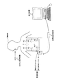
図1は、本発明にかかるカプセル型内視鏡の好適な実施の形態である無線型の被検体内情報取得システムの全体構成を示す模式図である。この被検体内情報取得システムは、一例としてカプセル型内視鏡を用いている。図1に示すように、無線型被検体内情報取得システムは、被検体1内に導入され、撮像機能により体腔内画像を撮像して受信装置2に対して映像信号などのデータ送信を行うカプセル型医療装置としてのカプセル型内視鏡3と、カプセル型内視鏡3から無線送信された体腔内画像データを受信する外部装置としての受信装置2とを備える。また、無線型被検体内情報取得システムは、受信装置2が受信した映像信号に基づいて体腔内画像を監視する表示装置4を備え、この受信装置2と表示装置4との間のデータの受け渡しは、受信装置2と表示装置4とを有線または無線接続することによって行う。
(Embodiment 1)
FIG. 1 is a schematic diagram showing an overall configuration of a wireless in-vivo information acquiring system which is a preferred embodiment of a capsule endoscope according to the present invention. This in-subject information acquisition system uses a capsule endoscope as an example. As shown in FIG. 1, the wireless in-vivo information acquiring system is a capsule that is introduced into a
受信装置2は、被検体1の対外表面に貼付される複数の受信用アンテナA1〜Anを有した無線ユニット2aと、複数の受信用アンテナA1〜Anを介して受信される無線信号の処理などを行う受信本体ユニット2bとを備え、これらユニットはコネクタなどを介して着脱可能に接続される。なお、受信用アンテナA1〜Anのそれぞれは、たとえば被検体1が着用可能なジャケットに備え付けられ、被検体1は、このジャケットを着用することによって受信用アンテナA1〜Anを装着するようにしてもよい。また、この場合、受信用アンテナA1〜Anは、ジャケットに対して着脱可能なものであってもよい。また、カプセル型内視鏡3を留置する場合には、受信用アンテナは1個であればよく、留置を行った後に、カプセル型内視鏡からの送信信号の受信を良好に行える位置に1個のアンテナを貼り付けることでもよい。
The receiving device 2 includes a radio unit 2a having a plurality of receiving antennas A1 to An attached to the outer surface of the
表示装置4は、カプセル型内視鏡3によって撮像された体腔内画像などを表示するためのものであり、図示しない無線装置によって受信されたデータをもとに画像表示を行うワークステーションなどのような構成を有する。具体的には、表示装置4は、CRTディスプレイ、液晶ディスプレイなどによって直接画像を表示する構成としても良いし、プリンタなどのように、他の媒体に画像を出力する構成としても良い。 The display device 4 is for displaying an in-vivo image captured by the capsule endoscope 3 and is like a workstation that displays an image based on data received by a wireless device (not shown). It has a configuration. Specifically, the display device 4 may be configured to directly display an image using a CRT display, a liquid crystal display, or the like, or may be configured to output an image to another medium such as a printer.
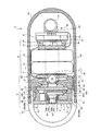
次に、図2、図3を用いてカプセル型内視鏡3について説明する。図2は、本発明にかかるカプセル型内視鏡3の構成を示す側断面図であり、図3は、図2に示したリジットフレキ配線基板を展開した上面図である。 Next, the capsule endoscope 3 will be described with reference to FIGS. FIG. 2 is a side sectional view showing a configuration of the capsule endoscope 3 according to the present invention, and FIG. 3 is a top view of the developed rigid-flex wiring board shown in FIG.
カプセル型内視鏡3は、図2に示すように、カプセル形状に形成された外装筐体6と、予め設定された所定の機能を実行するための機能実行手段として、体腔内を被検部位を照明するための照明光を出射する照明手段7と、機能実行手段として、照明光による反射光を受光して被検部位を撮像する撮像手段8と、照明手段7と撮像手段8の駆動制御および信号処理を行う制御手段9と、機能実行手段を駆動するための駆動電力を蓄積する蓄電手段10と、機能実行手段として、撮像手段8よって取得された画像データを被検体外部に無線送信する無線送信手段20を備える。
As shown in FIG. 2, the capsule endoscope 3 includes an
外装筐体6は、人が飲み込める程度の大きさのものであり、略半球状の先端カバー61と、筒形状の胴部カバー62とを弾性的に嵌合させて形成されている。配置用基板としての照明基板71、撮像基板81、スイッチ基板11、電源基板12および送信基板21は、後端部に略半円球形状の底部を有して先端部が円形状に開口した筒状の胴部カバー62内に挿入されている。先端カバー61(光学窓部材)は、略半球状のドーム形状であって、ドームの後側が円形状に開口している。この先端カバー61は、透明性あるいは透光性を有する透明部材、たとえば光学的性能や強度を確保するのに好ましいシクロオレフィンポリマーあるいはポリカーボネートなどの樹脂素材で成形され、照明手段7からの照明光を外装筐体6の外部に透過することを可能にするとともに、この照明光による被検体からの反射光を内部に透過することを可能にする。
The
また、胴部カバー62は、先端カバー61の後側に位置して、上記機能実行手段を覆う部材である。この胴部カバー62は、円筒状の胴部63と、略半球状のドーム形状の後端部64を一体に形成し、この胴部63の前側が円形状に開口している。この胴部カバー62は、強度を確保するのに好ましいポリサルフォンなどで形成され、照明手段7と、撮像手段8と、制御手段9と、蓄電手段10とを胴部63に収容し、無線送信手段20を後端部64に収容している。
The
先端カバー61の開口部には、開口端部の縁に沿って円筒形状の接合端部65が設けられている。また、胴部63の開口部には、開口端部の縁に沿って円筒形状の接合端部66が設けられている。各接合端部65,66は、先端カバー61と胴部カバー62を相互に接合する際に、外装筐体6の内外で重合して互いに接触する接合面65a,66aを有する。この実施の形態では、先端カバー61の接合端部65が外装筐体6の内側にあって、その外面が接合面65aをなし、胴部カバー62の接合端部66が外装筐体6の外側にあって、その内面が接合面66aをなし、接合面65aの外径と、接合面66aの内径とは、略一致して形成されている。なお、各接合端部65,66は、たとえば型成形時の抜き勾配の角度が0度のストレートで、かつほぼ同一の内外径にした筒形状に形成して互いの接合を容易にしてある。
The opening portion of the
接合面65aには、その全周に渡って突起65bが無端状に形成され、接合面66aには、その全周に渡って溝66bが無端状に形成されている。この突起65bと溝66bとは、接合面65aと66aが重合した状態で互いに係合される。このように、突起65bおよび溝66bは、互いに係合することによって、先端カバー61と胴部カバー62との接合した状態を保持する接合保持手段を構成している。
The
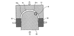
次に、先端カバー61の製造方法について説明する。先端カバー61は、図4に示すように、先端カバー61の外周側を形成するための外周用金型51と、先端カバー61の側周側を形成するための側周用金型52と、先端カバー61の内周側を形成するための内周用金型53とを組み合わせ、これら金型の間にシクロオレフィンポリマーあるいはポリマーカーボンなどの樹脂を射出して形成される。
Next, a method for manufacturing the
外周用金型51と内周用金型53とは、略半球ドーム形状の表面51a,53a(表面処理部)を有しており、これら表面51a,53aは、切削装置によって切削加工された後、研磨加工されている。この表面の一例を図5、図6に示す。図5、図6は、図4に示したB部分(内周用金型53の表面53a)の切削加工後の拡大表面を示す拡大断面図と、同じく研磨加工後の拡大表面を示す拡大断面図である。図5において、たとえば射出成型を行うための内周用金型53を切削装置によって加工すると、内周用金型53の表面53aに一定ピットの凹状の加工痕53bが形成される。この加工痕53bが成型品(先端カバー61)に転移されると、上述したごとく観察画像にフレアなどとなって移りこむことがある。
The
そこで、内周用金型53の表面53aにこの加工痕53bが残らないように、この切削後に研磨を行って、図6に示すように、内周用金型53の表面53aを鏡面に近い状態、たとえば表面粗さが数nm〜使用波長程度以下になるように仕上げる。また、この内周用金型53の表面53aを鏡面加工すると、成型品がたとえば濡れ性などの影響によって、鏡面加工された内周用金型53の表面53aに貼り付き、剥がれにくくなる。
Therefore, polishing is performed after this cutting so that the
このため、この実施の形態では、鏡面加工後の内周用金型53の表面53aを、図7に示すように、若干粗される程度にイオンビームを照射して表面処理する。ここで、「表面粗さ」とは、中心線平均粗さ(Ra)または十点平均粗さ(Rz)または最大高さ粗さ(Rmax)のいずれかのことであればよい。この実施の形態では、内周用金型53の表面53aを、鏡面加工後に表面粗さが0.5nm〜800nmとなるように表面仕上げを行うが、この「表面粗さが0.5nm〜800nm」とは、中心線平均粗さ(Ra)または十点平均粗さ(Rz)または最大高さ粗さ(Rmax)のいずれか一つが0.5nm〜800nmであれば、内周用金型53の表面53aが微細でかつランダムな凹凸の粗さを有するという条件を満たす。なお、この実施の形態においては、Raを0.5nm〜800nmとしてあるが、より具体的には、1.54nmとしてある。
For this reason, in this embodiment, the
図8は、上記表面処理を実現するための表面処理用イオン注入装置の構成の一例を示す構成図である。この表面処理用イオン注入装置は、電源54からの電源供給によって、イオン源55が真空チャンバー56内に配置された内周用金型53に、イオンビームを加速してシャワー状に衝突させる。なお、被注入試料である内周用金型53は、イオン源55から照射されるイオンビームが表面に均一に当たるように配置されている。また、真空チャンバー56内の真空排気は、ロータリーポンプ57によって真空ポンプ58を駆動させ、メインバルブ59を介して行われている。
FIG. 8 is a configuration diagram showing an example of a configuration of a surface treatment ion implantation apparatus for realizing the surface treatment. In this surface treatment ion implantation apparatus, by supplying power from a
このように、この実施の形態では、内周用金型53の表面53aにイオン源55からイオンビームを照射し、表面53aが若干粗される程度に、微細でかつランダムな凹凸が生じるように、内周用金型53の表面処理を行う。この内周用金型53を他の金型と組み合わせて成型品である先端カバー61を形成すると、内周用金型53に対する先端カバー61の貼り付き力が弱くなって、内周用金型53から先端カバー61が剥がれ易くなる。
As described above, in this embodiment, the
また、照明手段7は、図2に示すように、中央部分に通穴71aが設けられた円盤状に形成された照明基板71と、照明基板71の前面(図2中、先端カバー61側)に設けられた発光ダイオード、たとえば白色LEDなどの6つの発光体72と、後面(図2中、撮像基板81側)にLED72を駆動するための回路を構成するチップ部品74とを備え、LED72からの照明光は、先端カバー61を介して外部に照射されている。
Further, as shown in FIG. 2, the illuminating means 7 includes an illuminating
これらのLED72は、後述する撮像手段8の光学系としての結像レンズ83周辺で、かつ照明基板71に等間隔で配置されている。撮像手段8は、図2に示すように、円盤状に形成された撮像基板81と、撮像基板81の前面(図2中、照明基板71側)に設けられたCCDやCMOSなどの固体撮像素子82と、固体撮像素子82に被写体の像を結像させる結像レンズ83とを備える。結像レンズ83は、固体撮像素子82の前面(図2中、照明基板71側)に設けられており、被写体側に位置して可動枠84aに設けられる第1レンズ83aおよび第2レンズ83bとから構成される。可動枠84aと固定枠84bは、第1のレンズ83aおよび第2レンズ83bを光軸に沿って移動させるピント調整機構84を構成している。また、可動枠84aは、照明基板71の通穴71aに挿通しており、結像レンズ83の光軸を照明基板71の前面に向けている。これにより、撮像手段8は、照明手段7の照明光によって照らされた範囲を撮像することができる。また、撮像基板81の前面には、固体撮像素子82を囲む態様で、固体撮像素子82を駆動するための回路を構成するチップ部品85が設けられている。
These
制御手段9は、図2および図3に示すように、DSP(ディジタル シグナル プロセッサ)91を有し、DSP91は、撮像基板81の後面でチップ部品92に囲まれる態様で設けられている。このDSP91は、カプセル型内視鏡3の駆動制御の中枢を司り、固体撮像素子82の駆動制御および出力信号処理、照明手段7の駆動制御を行う。なお、撮像基板81の後面のチップ部品92は、DSP91から出力される映像信号およびクロック信号の2つの信号を、無線送信手段20から送信するにあたり、1つの信号にミキシングする機能などを有する半導体部材である。
As shown in FIGS. 2 and 3, the control means 9 has a DSP (digital signal processor) 91, and the
蓄電手段10は、図2に示すように、酸化銀電池などのボタン型乾電池13と、円盤形状に形成されたスイッチ基板11と、リードスイッチ14および電源制御IC15を有し、スイッチ基板11の前面(図2中、撮像基板81側)に設けられるスイッチ部16と、電源部18とを備える。ボタン型乾電池13は、複数個、たとえばこの実施の形態では、2個を直列にして負極キャップ側を後側に向けて配置してある。なお、これら電池13は、酸化銀電池に限定されるものではなく、たとえば充電式電池、発電式電池などを用いても良く、個数も2個に限定されるものではない。また、スイッチ基板11の後面には、板バネで形成された接点17が設けられ、この接点17は、ボタン型乾電池13の正極缶に接触して、ボタン型乾電池13を板バネの付勢力で、後側(図2中、電源基板12側)に付勢している。
As shown in FIG. 2, the power storage means 10 includes a button type
電源部18は、円盤形状に形成された電源基板12と、電源基板12の後面(図2中、後端部64側)に設けられたレギュレータ19を有している。レギュレータ19は、常にシステムに必要な一定の電圧を得るために、ボタン型乾電池13で得られる電圧をたとえば降圧などのコントロールを行う。また、図には明示してないが、電源基板12の前面(図2中、スイッチ基板11側)には、ボタン型乾電池13の負極キャップと接触する接点が設けられている。この実施の形態において、蓄電手段10は、スイッチ基板11と電源基板12の間に複数のボタン型乾電池13を直列に接続配置して各機能実行手段への電源供給を可能にする。
The
無線送信手段20は、図9に示すように、円筒形状に形成され、かつ内部に空間領域を有する送信基板21と、送信基板21の一方の面に設けられた発振回路22と、送信基板21のもう一方の面(図2中、後端部64側の後面)に設けられたアンテナ23と、電極24とを備える。アンテナ23は、図9に示すように、送信基板21の後面の略中央に、コイル状に構成されている。このアンテナ23は、カプセル型内視鏡3の外装筐体6のうち、胴部カバー62のドーム形状の後端部64内の略中央に配置されている。
As illustrated in FIG. 9, the
また、送信基板21の一方の面には、発振回路22とともに、関連する電子部品(図示せず)が配設され、この電子部品は、たとえば薄肉の金属ケースにて覆われている。電極24は、送信基板21の側面に形成されたサイドスルーホールからなり、前側(DSP91側)から延びるフレキシブル基板31と半田、もしくは導電樹脂にて電気的に接続される。さらにフレキシブル基板31は、図9に示すように、コイル状のアンテナ23を避けて送信基板21に配置される。この無線送信手段20は、上記チップ部品92(半導体部材)でミキシングした信号から一定の周波数・振幅・波形を持つ信号を発振回路22によって取り出し、この取り出した信号をアンテナ23からカプセル型内視鏡3の外部に送信する。
In addition, on one surface of the
また、照明基板71、撮像基板81、スイッチ基板11、電源基板12および送信基板21は、リジット基板からなる。図3に示すように、これらリジット基板は、一連のフレキシブル基板31をそれぞれ挟む態様で設けられて、リジットフレキ配線基板32を構成している。すなわち、各リジット基板は、フレキシブル基板31を介して、照明基板71、撮像基板81、スイッチ基板11、電源基板12、送信基板21の順で所定間隔おきに配設され、互いに電気的に接続されている。そして、このリジットフレキ配線基板32のフレキシブル基板31を折り曲げることによって、図2に示す態様で、照明基板71、撮像基板81、スイッチ基板11、電源基板12および送信基板21は、先端カバー61側と後端部64側の前後方向に積層して配置される。
The
このように、この実施の形態では、表面53aが微細でかつランダムな凹凸が生じるように表面処理された内周用金型53を用いて射出成型によって先端カバー61を形成するので、内周用金型53から先端カバー61が剥がれ易くなるとともに、この金型表面に残存する微細な凹凸が成型品(先端カバー61)に転移されても、画像の撮像時にフレアなどの発生を防ぎ、カプセル型医療装置の撮像性能を損なわずに、先端カバーの成型性能を向上できる。なお、本実施の形態では、内周用金型53の表面53aを処理したが、同様に、外周用金型51の表面51aを処理してもよい。また、このとき、内周用金型53、外周用金型51のどちらか一方のみでもよいし、いずれも処理することにより、より一層の効果が得られる場合もある。
Thus, in this embodiment, since the
(変形例)
上述したカプセル型内視鏡3の製造方法では、内周用金型53の表面53aをイオンビームで表面処理したが、本発明はこれに限らず、腐食性の薬品、たとえば低濃度の塩化第二鉄液、硝酸、酢酸や燐酸もしくはそれらの混合液などによって金型の表面加工を行い、上述した微細でかつランダムな凹凸の粗さを有する表面53aを形成することも可能である。
(Modification)
In the method of manufacturing the capsule endoscope 3 described above, the
また、たとえばCVD(Chemical Vapor Deposition:化学的気層成長法)による化学蒸着プロセスに用いる蒸着装置を使用して、内周用金型53の表面53aに一定の粗度を得られるコーティングを行い、上述した微細でかつランダムな凹凸の粗さを有する表面53aを形成することも可能である。
Further, for example, by using a vapor deposition apparatus used for a chemical vapor deposition process by CVD (Chemical Vapor Deposition), a coating capable of obtaining a certain degree of roughness is performed on the
これらの変形例においても、実施の形態1と同様に、内周用金型53から先端カバー61が剥がれ易くなるとともに、この金型表面に残存する微細な凹凸が成型品(先端カバー61)に転移されても、画像の撮像時にフレアなどの発生を防ぎ、カプセル型医療装置の撮像性能を損なわずに、先端カバーの成型性能を向上できる。
Also in these modified examples, as in the first embodiment, the
(付記項1)
先端カバーの開口した接合端部と、胴部カバーの開口した接合端部とを接合させ、被検体内へ導入可能なカプセル形状に形成し、前記胴部カバー内に収容された撮像手段で、前記先端カバーを介して外部の被写体を撮像可能なカプセル型医療装置の製造方法にて、
前記先端カバーを形成するための略半球ドーム形状の金型の表面を研磨した後に、微細でかつランダムな凹凸の粗さを有する表面処理を施す表面処理工程と、
前記表面処理工程で表面処理を施した金型を用い、射出成型によって略半球ドーム形状の前記先端カバーを形成するカバー形成工程と、
を含むことを特徴とするカプセル型医療装置の製造方法。
(Additional item 1)
With the imaging means accommodated in the capsule cover that can be introduced into the subject by joining the joint end opened in the tip cover and the joint end opened in the trunk cover, In a method for manufacturing a capsule medical device capable of imaging an external subject via the tip cover,
A surface treatment step of applying a surface treatment having a fine and random roughness after polishing the surface of a substantially hemispherical dome-shaped mold for forming the tip cover;
Using a mold that has been surface-treated in the surface treatment step, a cover forming step of forming the tip cover having a substantially hemispherical dome shape by injection molding,
A method for manufacturing a capsule medical device, comprising:
(付記項2)
前記表面処理工程は、イオンビームを前記金型表面へ加速して衝突させるイオンビーム加工を行うことを特徴とする付記項1に記載のカプセル型医療装置の製造方法。
(Appendix 2)
The method of manufacturing a capsule medical device according to
(付記項3)
前記表面処理工程は、腐食性薬品により前記金型表面を腐食させる金型表面加工を行うことを特徴とする付記項1に記載のカプセル型医療装置の製造方法。
(Additional Item 3)
2. The capsule medical device manufacturing method according to
(付記項4)
前記表面処理工程は、前記金型表面を所定の粗度を得られるコーティング処理を行うことを特徴とする付記項1に記載のカプセル型医療装置の製造方法。
(Appendix 4)
The method for manufacturing a capsule medical device according to
1 被検体
2 受信装置
2a 無線ユニット
2b 受信本体ユニット
3 カプセル型内視鏡
4 表示装置
6 外装筐体
7 照明手段
8 撮像手段
9 制御手段
10 蓄電手段
11 スイッチ基板
12 電源基板
13 ボタン型乾電池
13 電池
14 リードスイッチ
16 スイッチ部
17 接点
18 電源部
19 レギュレータ
20 無線送信手段
21 送信基板
22 発振回路
23 アンテナ
24 電極
31 フレキシブル基板
32 リジットフレキ配線基板
51 外周用金型
51a 外周用金型の表面
52 側周用金型
53 内周用金型
53a 内周用金型の表面
53b 加工痕
54 電源
55 イオン源
56 真空チャンバー
57 ロータリーポンプ
58 真空ポンプ
59 メインバルブ
61 先端カバー
62 胴部カバー
63 胴部
64 後端部
65,66 接合端部
65a,66a 接合面
65b 突起
66b 溝
71 照明基板
71a 通穴
72 発光体(LED)
74,85,92 チップ部品
81 撮像基板
82 固体撮像素子
83 結像レンズ
83a,83b レンズ
84 ピント調整機構
84a 可動枠
84b 固定枠
A1〜An 受信用アンテナ
15 電源制御IC
DESCRIPTION OF
74, 85, 92
Claims (2)
2. The device according to claim 1, wherein the dome shape is substantially hemispherical and can be a part of an exterior of a capsule endoscope, and has the surface treatment portion on both the front surface and the back surface. An optical window member for a capsule endoscope.
Priority Applications (6)
| Application Number | Priority Date | Filing Date | Title |
|---|---|---|---|
| JP2005263106A JP2007075162A (en) | 2005-09-09 | 2005-09-09 | Optical window member for capsule type endoscope |
| PCT/JP2006/317864 WO2007029814A1 (en) | 2005-09-09 | 2006-09-08 | Optical window member for capsule type endoscope |
| AU2006288207A AU2006288207B2 (en) | 2005-09-09 | 2006-09-08 | Optical window member for capsule type endoscope |
| CNA2006800323158A CN101257830A (en) | 2005-09-09 | 2006-09-08 | Optical window member for capsule type endoscope |
| EP06797718.1A EP1922982B1 (en) | 2005-09-09 | 2006-09-08 | Optical window member for capsule type endoscope |
| US11/571,415 US20080319267A1 (en) | 2005-09-09 | 2006-09-08 | Optical Window Member for Capsule Endoscope |
Applications Claiming Priority (1)
| Application Number | Priority Date | Filing Date | Title |
|---|---|---|---|
| JP2005263106A JP2007075162A (en) | 2005-09-09 | 2005-09-09 | Optical window member for capsule type endoscope |
Publications (2)
| Publication Number | Publication Date |
|---|---|
| JP2007075162A true JP2007075162A (en) | 2007-03-29 |
| JP2007075162A5 JP2007075162A5 (en) | 2007-08-16 |
Family
ID=37835929
Family Applications (1)
| Application Number | Title | Priority Date | Filing Date |
|---|---|---|---|
| JP2005263106A Pending JP2007075162A (en) | 2005-09-09 | 2005-09-09 | Optical window member for capsule type endoscope |
Country Status (6)
| Country | Link |
|---|---|
| US (1) | US20080319267A1 (en) |
| EP (1) | EP1922982B1 (en) |
| JP (1) | JP2007075162A (en) |
| CN (1) | CN101257830A (en) |
| AU (1) | AU2006288207B2 (en) |
| WO (1) | WO2007029814A1 (en) |
Cited By (4)
| Publication number | Priority date | Publication date | Assignee | Title |
|---|---|---|---|---|
| JP2008278962A (en) * | 2007-05-08 | 2008-11-20 | Olympus Medical Systems Corp | Capsule type medical device |
| JP2012223988A (en) * | 2011-04-20 | 2012-11-15 | Olympus Corp | Injection molding mold for dome shaped injection-molded article and dome shaped injection-molded article |
| JP2013048826A (en) * | 2011-08-31 | 2013-03-14 | Olympus Corp | Capsule type medical device |
| KR20170088334A (en) * | 2014-09-23 | 2017-08-01 | 스콧 밀러 | Optical coupler for optical imaging visualiziion device |
Families Citing this family (5)
| Publication number | Priority date | Publication date | Assignee | Title |
|---|---|---|---|---|
| JP5096090B2 (en) * | 2007-09-19 | 2012-12-12 | オリンパスメディカルシステムズ株式会社 | In-vivo image receiving apparatus and in-vivo image acquisition system |
| JP4584357B2 (en) * | 2008-12-09 | 2010-11-17 | オリンパスメディカルシステムズ株式会社 | Capsule type medical device and manufacturing method thereof |
| TW201028125A (en) | 2009-01-19 | 2010-08-01 | hui-yu Zhang | Micro image pick-up apparatus |
| US10548467B2 (en) | 2015-06-02 | 2020-02-04 | GI Scientific, LLC | Conductive optical element |
| US10856724B2 (en) | 2015-07-21 | 2020-12-08 | GI Scientific, LLC | Endoscope accessory with angularly adjustable exit portal |
Citations (2)
| Publication number | Priority date | Publication date | Assignee | Title |
|---|---|---|---|---|
| JPH0216017A (en) * | 1988-05-07 | 1990-01-19 | Bayer Ag | Method and mold for manufacturing molded part from fluid reaction mixture |
| JP2005031538A (en) * | 2003-07-10 | 2005-02-03 | Olympus Corp | Optical element with antireflection surface, optical system having optical element with antireflection surface, and optical equipment equipped with optical system having optical element with antireflection surface |
Family Cites Families (7)
| Publication number | Priority date | Publication date | Assignee | Title |
|---|---|---|---|---|
| JPH05171398A (en) * | 1991-12-25 | 1993-07-09 | Chugoku Kako Kk | Production of composite product having sprayed metal layer and mold release agent used therefor |
| US7179536B1 (en) * | 1999-09-29 | 2007-02-20 | Konica Corporation | Optical element having a low surface roughness, an optical pickup device including the optical element, and a die for making the optical element |
| JP4524515B2 (en) * | 2000-07-10 | 2010-08-18 | 富士電機デバイステクノロジー株式会社 | Method for producing press-molding mold for glass substrate for magnetic disk and method for producing glass substrate for magnetic disk |
| JP4149838B2 (en) * | 2003-03-04 | 2008-09-17 | オリンパス株式会社 | Capsule medical device |
| JP3993566B2 (en) * | 2004-01-22 | 2007-10-17 | オリンパス株式会社 | Capsule endoscope |
| JP4430959B2 (en) * | 2004-02-27 | 2010-03-10 | 東海カーボン株式会社 | Mold |
| US7357503B2 (en) * | 2004-03-02 | 2008-04-15 | Essilor International Compagnie Generale D'optique | Ophthalmic lens with an optically transparent composite film exhibiting both impact resistance property and polarizing property, and a process for its manufacture |
-
2005
- 2005-09-09 JP JP2005263106A patent/JP2007075162A/en active Pending
-
2006
- 2006-09-08 AU AU2006288207A patent/AU2006288207B2/en not_active Ceased
- 2006-09-08 WO PCT/JP2006/317864 patent/WO2007029814A1/en active Application Filing
- 2006-09-08 CN CNA2006800323158A patent/CN101257830A/en active Pending
- 2006-09-08 US US11/571,415 patent/US20080319267A1/en not_active Abandoned
- 2006-09-08 EP EP06797718.1A patent/EP1922982B1/en not_active Not-in-force
Patent Citations (2)
| Publication number | Priority date | Publication date | Assignee | Title |
|---|---|---|---|---|
| JPH0216017A (en) * | 1988-05-07 | 1990-01-19 | Bayer Ag | Method and mold for manufacturing molded part from fluid reaction mixture |
| JP2005031538A (en) * | 2003-07-10 | 2005-02-03 | Olympus Corp | Optical element with antireflection surface, optical system having optical element with antireflection surface, and optical equipment equipped with optical system having optical element with antireflection surface |
Cited By (11)
| Publication number | Priority date | Publication date | Assignee | Title |
|---|---|---|---|---|
| JP2008278962A (en) * | 2007-05-08 | 2008-11-20 | Olympus Medical Systems Corp | Capsule type medical device |
| WO2008139796A1 (en) * | 2007-05-08 | 2008-11-20 | Olympus Medical Systems Corp. | Capsule medical device and method of manufacturing capsule medical device |
| US8353821B2 (en) | 2007-05-08 | 2013-01-15 | Olympus Medical Systems Corp. | Capsule-type medical apparatus and method of manufacturing capsule-type medical apparatus |
| US9538906B2 (en) | 2007-05-08 | 2017-01-10 | Olympus Corporation | Capsule-type medical apparatus and method of manufacturing capsule-type medical apparatus |
| JP2012223988A (en) * | 2011-04-20 | 2012-11-15 | Olympus Corp | Injection molding mold for dome shaped injection-molded article and dome shaped injection-molded article |
| JP2013048826A (en) * | 2011-08-31 | 2013-03-14 | Olympus Corp | Capsule type medical device |
| KR20170088334A (en) * | 2014-09-23 | 2017-08-01 | 스콧 밀러 | Optical coupler for optical imaging visualiziion device |
| JP2017533792A (en) * | 2014-09-23 | 2017-11-16 | ミラー スコット | Optical coupler for optical imaging visualization system |
| KR102424385B1 (en) * | 2014-09-23 | 2022-07-25 | 스콧 밀러 | Optical coupler for optical imaging visualiziion device |
| KR20220116526A (en) * | 2014-09-23 | 2022-08-23 | 스콧 밀러 | Optical coupler for optical imaging visualiziion device |
| KR102617236B1 (en) | 2014-09-23 | 2023-12-27 | 스콧 밀러 | Optical coupler for optical imaging visualiziion device |
Also Published As
| Publication number | Publication date |
|---|---|
| EP1922982B1 (en) | 2015-03-25 |
| EP1922982A1 (en) | 2008-05-21 |
| EP1922982A4 (en) | 2009-11-04 |
| AU2006288207A1 (en) | 2007-03-15 |
| AU2006288207B2 (en) | 2009-09-03 |
| US20080319267A1 (en) | 2008-12-25 |
| CN101257830A (en) | 2008-09-03 |
| WO2007029814A1 (en) | 2007-03-15 |
Similar Documents
| Publication | Publication Date | Title |
|---|---|---|
| JP4598498B2 (en) | Intra-subject introduction device | |
| JP2007075162A (en) | Optical window member for capsule type endoscope | |
| JP4422679B2 (en) | Capsule endoscope and capsule endoscope system | |
| EP1702555B1 (en) | Capsule type medical device, medical capsule enclosure and production method therefor | |
| US8409077B2 (en) | Capsule endoscope | |
| JP4515747B2 (en) | Capsule medical device | |
| WO2004096029A1 (en) | Capsule endoscope and capsule endoscope system | |
| US10517468B2 (en) | Capsule medical device having positioning member with abutment surfaces | |
| US8226550B2 (en) | Capsule endoscope | |
| JP4363931B2 (en) | Capsule endoscope | |
| JP2005192820A (en) | Capsule type medical device | |
| JP2005204924A (en) | Capsule type endoscope | |
| JP4727214B2 (en) | Intra-subject introduction device | |
| JP4578874B2 (en) | Capsule medical device | |
| JP2005124963A (en) | Capsule type endoscope and imaging device | |
| JP4578899B2 (en) | Method for manufacturing in-subject introduction device | |
| JP2005124961A (en) | Capsule type medical device | |
| JP2005198879A (en) | Capsule type medical device | |
| JP2006149462A (en) | Device for acquiring information inside subject | |
| JP2005204927A (en) | Capsule type medical device | |
| JP2006149461A (en) | Device for acquiring information inside subject |
Legal Events
| Date | Code | Title | Description |
|---|---|---|---|
| A521 | Written amendment |
Free format text: JAPANESE INTERMEDIATE CODE: A523 Effective date: 20070322 |
|
| A521 | Written amendment |
Free format text: JAPANESE INTERMEDIATE CODE: A523 Effective date: 20070703 |
|
| A621 | Written request for application examination |
Free format text: JAPANESE INTERMEDIATE CODE: A621 Effective date: 20070703 |
|
| A131 | Notification of reasons for refusal |
Free format text: JAPANESE INTERMEDIATE CODE: A131 Effective date: 20100216 |
|
| A521 | Written amendment |
Free format text: JAPANESE INTERMEDIATE CODE: A523 Effective date: 20100416 |
|
| A02 | Decision of refusal |
Free format text: JAPANESE INTERMEDIATE CODE: A02 Effective date: 20100511 |