EP2196116B1 - Drive for a coffee brewing device and coffee brewing device - Google Patents
Drive for a coffee brewing device and coffee brewing device Download PDFInfo
- Publication number
- EP2196116B1 EP2196116B1 EP09015096A EP09015096A EP2196116B1 EP 2196116 B1 EP2196116 B1 EP 2196116B1 EP 09015096 A EP09015096 A EP 09015096A EP 09015096 A EP09015096 A EP 09015096A EP 2196116 B1 EP2196116 B1 EP 2196116B1
- Authority
- EP
- European Patent Office
- Prior art keywords
- housing
- drive
- gearwheel
- gear
- linear guide
- Prior art date
- Legal status (The legal status is an assumption and is not a legal conclusion. Google has not performed a legal analysis and makes no representation as to the accuracy of the status listed.)
- Active
Links
- 238000013016 damping Methods 0.000 claims abstract description 6
- 229910052751 metal Inorganic materials 0.000 claims description 13
- 239000002184 metal Substances 0.000 claims description 13
- 230000005540 biological transmission Effects 0.000 claims description 7
- 239000000463 material Substances 0.000 claims description 4
- 239000012466 permeate Substances 0.000 claims 1
- 239000004033 plastic Substances 0.000 description 6
- 229920003023 plastic Polymers 0.000 description 6
- 230000008878 coupling Effects 0.000 description 5
- 238000010168 coupling process Methods 0.000 description 5
- 238000005859 coupling reaction Methods 0.000 description 5
- 238000005452 bending Methods 0.000 description 4
- 238000010009 beating Methods 0.000 description 2
- 230000001419 dependent effect Effects 0.000 description 2
- 238000011161 development Methods 0.000 description 2
- 230000018109 developmental process Effects 0.000 description 2
- 230000002093 peripheral effect Effects 0.000 description 2
- 239000000843 powder Substances 0.000 description 2
- XLYOFNOQVPJJNP-UHFFFAOYSA-N water Substances O XLYOFNOQVPJJNP-UHFFFAOYSA-N 0.000 description 2
- 235000010678 Paulownia tomentosa Nutrition 0.000 description 1
- 240000002834 Paulownia tomentosa Species 0.000 description 1
- 229910000831 Steel Inorganic materials 0.000 description 1
- 239000011358 absorbing material Substances 0.000 description 1
- 230000002411 adverse Effects 0.000 description 1
- 229910052782 aluminium Inorganic materials 0.000 description 1
- XAGFODPZIPBFFR-UHFFFAOYSA-N aluminium Chemical compound [Al] XAGFODPZIPBFFR-UHFFFAOYSA-N 0.000 description 1
- 230000002238 attenuated effect Effects 0.000 description 1
- 230000015572 biosynthetic process Effects 0.000 description 1
- 238000013124 brewing process Methods 0.000 description 1
- 238000010276 construction Methods 0.000 description 1
- 238000009413 insulation Methods 0.000 description 1
- 150000002739 metals Chemical class 0.000 description 1
- 210000000056 organ Anatomy 0.000 description 1
- 239000007787 solid Substances 0.000 description 1
- 230000006641 stabilisation Effects 0.000 description 1
- 238000011105 stabilization Methods 0.000 description 1
- 239000010959 steel Substances 0.000 description 1
- -1 steel or aluminum Chemical class 0.000 description 1
- 239000000725 suspension Substances 0.000 description 1
Images


Classifications
-
- A—HUMAN NECESSITIES
- A47—FURNITURE; DOMESTIC ARTICLES OR APPLIANCES; COFFEE MILLS; SPICE MILLS; SUCTION CLEANERS IN GENERAL
- A47J—KITCHEN EQUIPMENT; COFFEE MILLS; SPICE MILLS; APPARATUS FOR MAKING BEVERAGES
- A47J31/00—Apparatus for making beverages
- A47J31/24—Coffee-making apparatus in which hot water is passed through the filter under pressure, i.e. in which the coffee grounds are extracted under pressure
- A47J31/34—Coffee-making apparatus in which hot water is passed through the filter under pressure, i.e. in which the coffee grounds are extracted under pressure with hot water under liquid pressure
- A47J31/36—Coffee-making apparatus in which hot water is passed through the filter under pressure, i.e. in which the coffee grounds are extracted under pressure with hot water under liquid pressure with mechanical pressure-producing means
- A47J31/3604—Coffee-making apparatus in which hot water is passed through the filter under pressure, i.e. in which the coffee grounds are extracted under pressure with hot water under liquid pressure with mechanical pressure-producing means with a mechanism arranged to move the brewing chamber between loading, infusing and ejecting stations
- A47J31/3609—Loose coffee being employed
- A47J31/3614—Means to perform transfer from a loading position to an infusing position
-
- Y—GENERAL TAGGING OF NEW TECHNOLOGICAL DEVELOPMENTS; GENERAL TAGGING OF CROSS-SECTIONAL TECHNOLOGIES SPANNING OVER SEVERAL SECTIONS OF THE IPC; TECHNICAL SUBJECTS COVERED BY FORMER USPC CROSS-REFERENCE ART COLLECTIONS [XRACs] AND DIGESTS
- Y10—TECHNICAL SUBJECTS COVERED BY FORMER USPC
- Y10T—TECHNICAL SUBJECTS COVERED BY FORMER US CLASSIFICATION
- Y10T74/00—Machine element or mechanism
- Y10T74/18—Mechanical movements
- Y10T74/18568—Reciprocating or oscillating to or from alternating rotary
- Y10T74/18576—Reciprocating or oscillating to or from alternating rotary including screw and nut
- Y10T74/18648—Carriage surrounding, guided by, and primarily supported by member other than screw [e.g., linear guide, etc.]
Definitions
- the invention relates to a drive for a coffee brewing device according to the preamble of claim 1 and a coffee brewing device with such a drive according to claim 17.
- the brewing unit develops during operation a relatively high noise emission, which is due in particular to the operation of a drive device which serves to move various movable parts, in particular the brewing piston.
- the drive device comprises a plurality of toothed gears, one of which is drivable by means of a drive motor and another is coupled to the brewing piston in such a way that the brewing piston can be moved back and forth along an axis by means of the drive motor.
- the drive comprises: a first gear having an internal thread, via which this first gear is rotatably mounted on an outer thread of a guide cylinder, so that the first gear is movable during rotation along a cylinder axis of the guide cylinder; a second gear engaged with said first gear for driving the first gear along the cylinder axis; a housing in which the first gear is received; and a brewing piston, which is coupled to the housing, so that this brewing piston is movable along with the first gear along the cylinder axis.
- the drive comprises a linear guide for the housing, which linear guide extends at a distance parallel to the cylinder axis and with which the housing is engaged so that a movement of the housing relative to the linear guide is prevented in a direction radial to the cylinder axis. Furthermore, a rotation axis of the second gear is arranged at a predetermined distance relative to the linear guide.
- housing in which the first gear is received is to be understood in the context of this description quite generally a component which performs the function of a coupling between the first gear and the brewing piston and to the first gear at least partially encloses.
- the "housing” can also be designed as a kind of cage, which encloses the first gear.
- the cage can have several, sometimes large perforations.
- the housing which surrounds the first gear, is linearly guided by the linear guide during a movement along the cylinder axis of the guide cylinder prevents the housing from exceeding the linear guide in a direction radial to the cylinder axis beyond certain (predetermined) tolerances can move.
- the Fig. 2 and 3 show the coffee brewing device 2 according Fig. 1 from different perspectives.
- the drive 1 comprises a linear guide 80, on which the housing 50 is guided during its lifting movement along the guide cylinder 20.
- the housing is in a manner to be explained in more detail below with the linear guide 80 in engagement.
- the linear guide 80 itself comprises two guide rods 80-1 and 80-2, which ideally have a U-shaped or H-shaped cross-sectional profile in order to increase their bending stiffness and thus to reduce their natural vibration.
- the rods 80-1 and 80-2 are mounted rigidly relative to the guide cylinder 20 on a base 90 of the device 2.
- the second gear 30 which is designed so that the upper ends of the guide rods 80-1 and 80-2 are connected to each other via a boom 81.
- the axis of rotation 32 of the second gear 30 is supported on one arm 81 and the other on the base 90, whereby the guide 80 also serves for vibration-free suspension of this gear 30, especially since the axis of rotation 32 of the second gear 30 at opposite ends both at the Base 90 and the boom 81 each at a predetermined distance relative to the linear guide 80 and relative to the guide rods 80-1 and 80-2 is held.
- the axis of rotation 32 of the second gear 30 is particularly effective against tilting or bending relative to the linear guide 80 secured.
- the guide 80 and the second gear 30 form a particularly compact and space-saving common structural unit, which does not adversely affect the height of the coffee brewing device 2, that is, does not increase the height of the coffee brewing device.
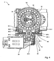
- FIG. 4 finally shows a plan view of the coffee brewing device 2 of FIG. 1 when the housing 50 is open.
- the first gearwheel 10, which is mounted in the housing 50, can be seen again.
- the first gear 10 is rotated by the second gear 30, which in turn is driven by the motor 35.
- the first gear 10 together with the housing 50 and the brewing piston 40 coupled thereto can be moved in a direction perpendicular to the plane of the page and thus along the guide cylinder 20.
- the guide rods 80-1, 80-2 each have an approximately H-shaped cross-sectional profile with a groove 83-1 and 83-2, in which grooves 83-1 and 83-2 respectively a projection 84-1 and 84-2, which is formed on the housing 50.
- the guidance of the projections 84-1, 84-2 in the corresponding groove 83-1, 83-2 prevents a vibration movement of the housing radially to the cylinder axis 22, which causes a noise reduction.
- the boom 81 in the present case is rigidly connected to each of the guide rods 80-1 and 80-2. Since the housing 50 is in engagement with the linear guide 80 or the respective guide rod 80-1 or 80-2 such that movement of the housing 50 relative to the respective guide rod 80-1 or 80-2 respectively in a direction to the cylinder axis 22nd Radial direction is prevented and since the axis of rotation 32 of the second gear 30 is disposed at a predetermined distance relative to the linear guide 80 and to the respective guide rod 80-1 or 80-2, it is ensured in the present case that the distance between the cylinder axis 22 and the axis of rotation of the first gear 10 and the rotational axis 32 of the second gear 30 is held constant, regardless of the position of the brewing piston 40 and the first gear 10 along the cylinder axis 22. The first gear 10 is thus opposite the second gear 30th during a lifting movement along the cylinder axis 22 (within predetermined tolerances) out.
- the coffee brewing apparatus 2 can preferably be mounted on a base support in rubber-bearing fashion in order to exclude a vibration transmission to a housing.
- the drive 1, shown only by way of example here, alone makes it possible to achieve a clear reduction in noise, and is structurally simple and compact in design and therefore inexpensive to produce.
Abstract
Description
Die Erfindung betrifft einen Antrieb für eine Kaffeebrühvorrichtung nach dem Oberbegriff des Anspruchs 1 und eine Kaffeebrühvorrichtung mit einem solchen Antrieb nach Anspruch 17.The invention relates to a drive for a coffee brewing device according to the preamble of
Aus der Patentschrift
Es ist Aufgabe der vorliegenden Erfindung, die beschriebenen Nachteile zu vermeiden und einen geräuschärmeren Antrieb für eine Kaffeebrühvorrichtung zur Verfügung zu stellen, der konstruktiv einfach und kompakt ausgestaltet, sowie kostengünstig herstellbar ist.It is an object of the present invention to avoid the disadvantages described and to provide a quieter drive for a coffee brewing device available, which structurally simple and compact designed, and is inexpensive to produce.
Diese Aufgabe wird durch einen Antrieb nach dem kennzeichnenden Teil des Anspruchs 1 gelöst.This object is achieved by a drive according to the characterizing part of
Der Antrieb umfasst: ein erstes Zahnrad mit einem Innengewinde, über welches dieses erste Zahnrad an einem Aussengewinde eines Führungszylinders drehbar gelagert ist, so dass das erste Zahnrad bei einer Drehung entlang einer Zylinderachse des Führungszylinders bewegbar ist; ein zweites Zahnrad, welches zum Antreiben des ersten Zahnrades entlang der Zylinderachse mit diesem ersten Zahnrad in Eingriff steht; ein Gehäuse, in welchem das erste Zahnrad aufgenommen ist; und einen Brühkolben, welcher an das Gehäuse gekoppelt ist, so dass dieser Brühkolben zusammen mit dem ersten Zahnrad entlang der Zylinderachse bewegbar ist.The drive comprises: a first gear having an internal thread, via which this first gear is rotatably mounted on an outer thread of a guide cylinder, so that the first gear is movable during rotation along a cylinder axis of the guide cylinder; a second gear engaged with said first gear for driving the first gear along the cylinder axis; a housing in which the first gear is received; and a brewing piston, which is coupled to the housing, so that this brewing piston is movable along with the first gear along the cylinder axis.
Gemäss der Erfindung umfasst der Antrieb eine Linearführung für das Gehäuse, welche Linearführung in einem Abstand parallel zur Zylinderachse verläuft und mit welcher das Gehäuse so in Eingriff steht, dass eine Bewegung des Gehäuses gegenüber der Linearführung in einer zur Zylinderachse radialen Richtung verhindert ist. Weiterhin ist eine Drehachse des zweiten Zahnrades in einem vorgegebenen Abstand relativ zu der Linearführung angeordnet.According to the invention, the drive comprises a linear guide for the housing, which linear guide extends at a distance parallel to the cylinder axis and with which the housing is engaged so that a movement of the housing relative to the linear guide is prevented in a direction radial to the cylinder axis. Furthermore, a rotation axis of the second gear is arranged at a predetermined distance relative to the linear guide.
Unter dem Begriff "Gehäuse, in welchem das erste Zahnrad aufgenommen ist" soll im Rahmen dieser Beschreibung ganz allgemein ein Bauteil verstanden werden, welches die Funktion einer Kopplung zwischen dem ersten Zahnrad und dem Brühkolben wahrnimmt und dazu das erste Zahnrad wenigstens teilweise umschliesst. Dabei kann das "Gehäuse" auch als eine Art Käfig ausgeführt sein, der das erste Zahnrad umschliesst. Der Käfig kann mehrere, teils grosse Lochungen aufweisen.The term "housing in which the first gear is received" is to be understood in the context of this description quite generally a component which performs the function of a coupling between the first gear and the brewing piston and to the first gear at least partially encloses. The "housing" can also be designed as a kind of cage, which encloses the first gear. The cage can have several, sometimes large perforations.
Dadurch, dass das Gehäuse, welches das erste Zahnrad umgibt, bei einer Bewegung entlang der Zylinderachse des Führungszylinders durch die Linearführung linear geführt ist, wird verhindert, dass sich das Gehäuse gegenüber der Linearführung in einer zur Zylinderachse radialen Richtung über bestimmte (vorgegebene) Toleranzen hinaus bewegen kann. Dadurch, dass zusätzlich die Drehachse des zweiten Zahnrades in einem vorgegebenen Abstand relativ zu der Linearführung angeordnet ist, wird erreicht, dass die räumliche Lage des zweiten Zahnrades bezüglich der Zylinderachse (innerhalb vorgegebener Toleranzen) konstant gehalten und somit stabilisiert wird, wenn durch Antreiben des zweiten Zahnrades (z.B. mittels eines Motors) das zweite Zahnrad in eine Drehung versetzt wird und aufgrund dieser Drehung das erste Zahnrad angetrieben und somit ebenfalls in eine Drehung versetzt wird und dabei - wegen der Verzahnung zwischen dem Innengewinde des ersten Zahnrades und dem Aussengewinde des Führungszylinders - in Längsrichtung der Zylinderachse bewegt wird. Radiale Schwingungen des zweiten Zahnrades bezüglich der Zylinderachse und somit auch radiale Schwingungen des zweiten Zahnrades bezüglich des ersten Zahnrades werden so im Betrieb des Antriebs unterdrückt bzw. zumindest limitiert. Dies verbessert die Laufruhe des Antriebs und reduziert Lärmemissionen im Betrieb.The fact that the housing, which surrounds the first gear, is linearly guided by the linear guide during a movement along the cylinder axis of the guide cylinder prevents the housing from exceeding the linear guide in a direction radial to the cylinder axis beyond certain (predetermined) tolerances can move. The fact that in addition the axis of rotation of the second gear is arranged at a predetermined distance relative to the linear guide, it is achieved that the spatial position of the second gear with respect to the cylinder axis (within predetermined tolerances) kept constant and thus stabilized when by driving the second Gear (eg by means of a motor), the second gear is rotated and due to this rotation, the first gear is driven and thus also rotated, and - because of the toothing between the internal thread of the first gear and the external thread of the guide cylinder Is moved longitudinally of the cylinder axis. Radial vibrations of the second gear relative to the cylinder axis and thus also radial vibrations of the second gear with respect to the first gear are suppressed during operation of the drive or at least limited. This improves the smooth running of the drive and reduces noise emissions during operation.
Gemäss einer Ausführungsform des Antriebs ist zwischen dem Gehäuse und dem ersten Zahnrad ein Drehlager ausgebildet ist, welches eine radiale Bewegung des Gehäuses (innerhalb vorgegebener Toleranzen) gegenüber dem ersten Zahnrad verhindert. Durch das Drehlager wird das erste Zahnrad an dem Gehäuse geführt, wodurch ein radiales und axiales Schlagen oder Schwingen des ersten Zahnrades und eine damit verbundene Geräuschentwicklung vermieden wird. Auf diese Weise werden radiale Schwingungen des zweiten Zahnrades relativ zum ersten Zahnrad zusätzlich gemindert und die Laufruhe der beiden Zahnräder relativ zueinander verbessert.According to one embodiment of the drive, a rotary bearing is formed between the housing and the first gear, which prevents a radial movement of the housing (within predetermined tolerances) relative to the first gear. By the pivot bearing the first gear is guided on the housing, whereby a radial and axial beating or swinging of the first gear and an associated noise is avoided. That way Radial vibrations of the second gear relative to the first gear additionally reduced and improved the smoothness of the two gears relative to each other.
Gemäss einer vorteilhaften Ausführungsform sind das Gehäuse und das erste Zahnrad so geformt und angepasst, dass diese das Drehlager bilden.According to an advantageous embodiment, the housing and the first gear are shaped and adapted so that they form the pivot bearing.
Eine konstruktiv besonders einfache Gestaltung des Drehlagers sieht dabei vor, dass dieses durch einen umlaufenden Anschlag am Gehäuse gebildet wird, gegen den ein zylindrischer Fortsatz des ersten Zahnrads anliegt. Natürlich ist es aber auch möglich, andere Lagerarten zu wählen, wenn dies im Rahmen der geforderten Dimensionierung des Antriebs akzeptabel ist, z.B. ein Kugellager, ein Wälzlager oder ein Zwischenstück, welches zumindest an einer der Reibflächen einen niedrigen Reibungswert aufweist.A structurally particularly simple design of the pivot bearing provides that this is formed by a peripheral stop on the housing, against which a cylindrical extension of the first gear rests. Of course, it is also possible to choose other types of bearings if this is acceptable within the required dimensioning of the drive, e.g. a ball bearing, a roller bearing or an intermediate piece, which has a low coefficient of friction at least on one of the friction surfaces.
Ein besonders geräuscharmer Lauf des Gehäuses und des ersten Zahnrads wird dadurch erzielt, dass diese gegenseitige Kontaktflächen aufweisen, die im Vergleich zu ihrem Grundmaterial mit reibungsärmeren Oberflächen versehen sind. Grundsätzlich ist es aber auch möglich, beide Teile aus einem Material herzustellen, das schon einen niedrigen Reibungswert aufweist. Durch diesen Reibungswert werden Schwingungen und damit Reibungsgeräusche reduziert.A particularly quiet running of the housing and the first gear is achieved in that they have mutual contact surfaces, which are provided in comparison to their base material with low-friction surfaces. In principle, it is also possible to produce both parts from a material that already has a low coefficient of friction. This friction value reduces vibrations and therefore friction noise.
Eine zusätzliche Geräuschminderung kann dadurch erreicht werden, dass das Gehäuse das erste Zahnrad vollständig umschliesst, mit Ausnahme einer Öffnung, welche für den Eingriff des zweiten Zahnrades erforderlich ist. Durch die vollständige Umschliessung werden Geräusche in dem Gehäuse gehalten. Das Gehäuse kann durch die Verwendung geräuschdämmender Materialien oder durch geeignete Bauformen den Schall zusätzlich dämpfen. Ausserdem verleiht die hohlkörperartige Grundform, welche sich durch die möglichst vollständige Umschliessung des Zahnrades ergibt, dem Gehäuse Stabilität, wodurch ein Schlagen oder Schwingen vermindert wird.An additional noise reduction can be achieved in that the housing completely encloses the first gear, with the exception of an opening which is required for the engagement of the second gear. By completely enclosing noises are held in the housing. The housing can additionally dampen the sound by using sound absorbing materials or suitable designs. In addition, the hollow body-like basic shape, which results from the most complete possible enclosure of the gear, gives the housing stability, whereby a beating or swinging is reduced.
In einer weiteren vorteilhaften Ausgestaltung ist das Gehäuse an den Brühkolben über eine Metallplatte, die sich in einer radial zur Zylinderachse verlaufenden Ebene erstreckt, gekoppelt. Weiter kann die Metallplatte wenigstens einen Teil des Gehäuses und/oder des Brühkolbens durchdringen. Diese Kopplung über eine Metallplatte hat gegenüber einer konventionellen (beispielsweise aus
In einer besonders vorteilhaften Ausgestaltung weist der Antrieb eine Basis auf, mit der ein unteres Ende der Linearführung und ein unteres Ende des Führungszylinders starr verbunden ist. Eine starre Verbindung verhindert eine Schwingungsbewegung dieser Bauteile gegeneinander und damit die Geräuschentwicklung zwischen diesen. Zusätzlich wird dadurch eine sehr genaue parallele Führung des Gehäuses gegenüber der Zylinderachse gewährleistet.In a particularly advantageous embodiment, the drive has a base to which a lower end of the linear guide and a lower end of the guide cylinder is rigidly connected. A rigid connection prevents vibration of these components against each other and thus the noise between them. In addition, this ensures a very accurate parallel guidance of the housing relative to the cylinder axis.
In einer besonders vorteilhaften Ausgestaltung ist ein unteres Ende einer Drehachse des zweiten Zahnrades an der Basis und ein oberes Ende dieser Drehachse an einem Ausleger der Linearführung befestigt. Die Befestigung der Drehachse des zweiten Zahnrades zwischen Basis und Ausleger der Linearführung sorgt dafür, dass die Drehachse des zweiten Zahnrades an mindestens zwei Punkten in einem vorgegebenen Abstand relativ zur Linearführung gehalten ist. Diese Anordnung gibt dem zweiten Zahnrad eine grosse Stabilität gegenüber der Zylinderachse und gegenüber dem ersten Zahnrad. Insbesondere Verkippungen und Verbiegungen der Drehachse des zweiten Zahnrades und damit verbundene Schwingungen des zweiten Zahnrades relativ zur Linearführung bzw. dem Gehäuse bzw. dem ersten Zahnrand können so besonders wirkungsvoll reduziert bzw. unterdrückt werden. Somit wird ein optimales und geräuscharmes Ineinandergreifen der beiden Zahnräder erreicht.In a particularly advantageous embodiment, a lower end of a rotation axis of the second gear is fixed to the base and an upper end of this rotation axis on a cantilever of the linear guide. The attachment of the axis of rotation of the second gear between the base and boom of the linear guide ensures that the axis of rotation of the second gear is held at least two points at a predetermined distance relative to the linear guide. This arrangement gives the second gear a great stability with respect to the cylinder axis and with respect to the first gear. In particular, tilting and bending of the axis of rotation of the second gear and associated vibrations of the second gear relative to the linear guide or the housing or the first tooth edge can be particularly effectively reduced or suppressed. Thus, an optimal and low noise meshing of the two gears is achieved.
In einer weiteren vorteilhaften Ausgestaltung verläuft die Linearführung an einer Seite des Gehäuses, die dem zweiten Zahnrad zugewandt ist. Somit kann einem Verkanten des Gehäuses gegenüber der Linearführung entgegengewirkt werden und die Laufruhe des Antriebs verbessert werden.In a further advantageous embodiment, the linear guide extends on one side of the housing, which faces the second gear. Thus, a tilting of the housing relative to the linear guide can be counteracted and the smoothness of the drive can be improved.
Die Gefahr dieses Verkantens des Gehäuses gegenüber der Linearführung kann auch dadurch gemindert werden, dass die Linearführung mindestens eine gerade Führungsstange umfasst, die wenigstens teilweise von dem Gehäuse umgriffen ist. Die Linearführung für das Gehäuse kann zusätzlich stabilisiert werden, wenn die Linearführung mehr als eine Führungsstange umfasst. Dadurch, dass das Gehäuse beispielsweise an zwei geraden Führungsstangen geführt ist, wird das Gehäuse bezüglich einer weiteren potentiellen Kippachse stabilisiert, was die Funktion des Antriebs zusätzlich verbessert.The risk of this tilting of the housing relative to the linear guide can also be reduced by the fact that the linear guide comprises at least one straight guide rod, which is at least partially encompassed by the housing. The linear guide for the housing can be additionally stabilized if the linear guide comprises more than one guide rod. The fact that the housing is guided for example on two straight guide rods, the housing is stabilized with respect to another potential tilt axis, which further improves the function of the drive.
In einer besonders bevorzugten Ausführungsform, weisen die jeweiligen Führungsstangen eine axial verlaufende Nut auf, in der ein jeweils am Gehäuse ausgebildeter Vorsprung eingreift. Die Nut und die am Gehäuse ausgebildeten Vorsprünge sind dabei hinsichtlich ihrer Form und Grösse derart aufeinander abgestimmt, dass ein Verkanten des Gehäuses an der Linearführung (über vorgegebene Toleranzen hinaus) verhindert wird. Weiter können dadurch auch relativ grosse Kräfte zwischen dem Gehäuse und der Linearführung übertragen werden.In a particularly preferred embodiment, the respective guide rods have an axially extending groove in which engages a respective projection formed on the housing. The groove and the projections formed on the housing are matched to one another in terms of their shape and size such that tilting of the housing on the linear guide (beyond predetermined tolerances) is prevented. Furthermore, it is also possible to transmit relatively large forces between the housing and the linear guide.
In besonders vorteilhafter Weise ist dabei die Nut in Richtung des zweiten Zahnrades geöffnet. Dadurch werden die zugeordneten Vorsprünge in die Nut gedrückt, sobald eine Kraftübertragung von dem zweiten Zahnrad auf das erste Zahnrad stattfindet, d.h. das erste Zahnrad angetrieben wird. Dies bewirkt, dass eine sozusagen selbststabilisierende Kopplung zwischen dem Gehäuse, in dem das erste Zahnrad gelagert ist, und der Linearführung unter Krafteinwirkung entsteht.In a particularly advantageous manner, the groove is open in the direction of the second gear. Thereby, the associated projections are pressed into the groove as soon as a power transmission from the second gear to the first gear takes place, i. the first gear is driven. This causes a so-called self-stabilizing coupling between the housing in which the first gear is mounted, and the linear guide is formed under force.
In einer weiteren Ausführungsform des Antriebs ist ein unteres Ende einer Drehachse des zweiten Zahnrades an der Basis des Antriebs und ein oberes Ende dieser Drehachse an einem Ausleger befestigt, welcher starr mit mindestens einer der jeweiligen Führungsstangen verbunden ist. Dadurch wird erreicht, dass der Abstand zwischen der Zylinderachse des Führungszylinders bzw. der Drehachse des ersten Zahnrades und der Drehachse des zweiten Zahnrades konstant gehalten ist, unabhängig von der Lage des Brühkolbens bzw. des ersten Zahnrades entlang der Zylinderachse. Die Drehachsen des ersten Zahnrads und des zweiten Zahnrads werden so relativ zueinander stabilisiert und Schwingungen der beiden Zahnräder in einer zu einer der jeweiligen Drehachsen radialen Richtung verhindert. Dadurch wird die Laufruhe des Antriebs verbessert und eine konstante Kraftübertragung der beiden Zahnräder über der ganzen Hubbewegung ergibt.In a further embodiment of the drive, a lower end of a rotation axis of the second gear at the base of the drive and an upper end of this rotation axis is fixed to a boom which is rigidly connected to at least one of the respective guide rods. This ensures that the distance between the cylinder axis of the guide cylinder and the axis of rotation of the first gear and the axis of rotation of the second gear is kept constant, regardless of the position of the brewing piston or the first gear along the cylinder axis. The axes of rotation of the first gear and the second gear are thus stabilized relative to each other and prevents vibrations of the two gears in a direction radial to one of the respective axes of rotation. As a result, the smoothness of the drive is improved and results in a constant power transmission of the two gears over the entire stroke.
Dadurch, dass der Abstand der Drehachsen des ersten und des zweiten Zahnrades mit grosser Präzision innerhalb vorgegebener Toleranzen kontrolliert ist, kann der Zahnradmodul (definiert als Verhältnis zwischen dem Durchmesser des jeweiligen Zahnrades und der Anzahl der Zähne des Zahnrades) relativ klein gewählt werden, was sich wiederum geräuschmindernd auswirkt.Characterized in that the distance of the axes of rotation of the first and second gear is controlled within predetermined tolerances with great precision, the gear module (defined as the ratio between the diameter of the respective gear and the number of teeth of the gear) can be chosen relatively small, which is again reduces noise.
In einer zusätzlichen vorteilhaften Ausgestaltung weist die Linearführung ein U- oder H-förmiges Querschnittsprofil auf. Derartig geformte Querschnittsprofile sind für eine gegenüber beispielsweise Rundprofilen erhöhte Biegesteifigkeit und damit Schwingungsarmut bekannt.In an additional advantageous embodiment, the linear guide has a U-shaped or H-shaped cross-sectional profile. Such shaped cross-sectional profiles are known for increased bending stiffness and thus low vibration compared with, for example, round profiles.
Eine konstruktiv besonders bevorzugte Ausgestaltung sieht vor, dass das Gehäuse einstückig daran ausgebildete Flansche aufweist, über welche es mit der Linearführung in Eingriff steht. Durch die Ausbildung der Flansche wird eine zusätzliche Öffnung des Gehäuses gegenüber der Umgebung vermieden, durch welche Öffnung Schall aus dem Inneren des Gehäuses in die Umgebung austreten könnte.A structurally particularly preferred embodiment provides that the housing has integrally formed thereon flanges, via which it is in engagement with the linear guide. The formation of the flanges avoids an additional opening of the housing relative to the environment, through which opening sound could escape from the interior of the housing into the environment.
Die Geräuschentwicklung kann zudem verringert werden, indem der Antrieb ein Übersetzungsverhältnis zwischen dem ersten Zahnrad und dem zweiten Zahnrad in einem Bereich zwischen 4 und 4,5 vorsieht. Ein solches Übersetzungsverhältnis ermöglicht eine verbesserte Kraftübertragung zwischen einem Motor und dem Brühkolben, wobei der Antrieb mit einer tieferen Drehzahl betrieben werden kann, was eine geringe Geräuschentwicklung verursacht.The noise can also be reduced by the drive provides a gear ratio between the first gear and the second gear in a range between 4 and 4.5. Such a transmission ratio allows an improved power transmission between a motor and the brewing piston, wherein the drive with a deeper Speed can be operated, which causes a low noise.
Die vorstehende Aufgabe wird auch durch eine Kaffeebrühvorrichtung nach dem kennzeichnenden Teil des Anspruchs 17 gelöst.The above object is also achieved by a coffee brewing device according to the characterizing part of claim 17.
Die schon in Verbindung mit dem Antrieb beschriebenen Vorteile werden auch durch die erfindungsgemässe Kaffeebrühvorrichtung erzielt.The advantages already described in connection with the drive are also achieved by the coffee brewing device according to the invention.
Bevorzugte Weiterbildungen dieser Kaffeebrühvorrichtung sind in den abhängigen Patentansprüchen angegeben.Preferred developments of this Kaffeebrühvorrichtung are given in the dependent claims.
Bevorzugte Weiterbildungen des erfindungsgemässen Antriebs sind in den abhängigen Patentansprüchen angegeben.Preferred developments of the inventive drive are given in the dependent claims.
So ist in einer bevorzugten Ausgestaltung vorgesehen, dass der Antrieb über ein Dämpfungselement an einem Grundträger befestigt ist. Durch das Dämpfungselement wird verhindert, dass der Grundträger oder weitere Teile akustisch zum Schwingen angeregt werden oder gar als Resonanzkörper wirken.Thus, it is provided in a preferred embodiment that the drive is attached via a damping element to a base support. By the damping element prevents the base support or other parts are acoustically excited to vibrate or even act as a resonator.
Bevorzugt besteht dabei das Dämpfungselement aus einem Gummimaterial. Durch ein Gummielement kann eine kostengünstig und auf den Frequenzbereich des Schalls abgestimmte Dämpfung erreicht werden.Preferably, the damping element consists of a rubber material. By a rubber element, a cost-effective and tuned to the frequency range of the sound attenuation can be achieved.
Weitere Einzelheiten der Erfindung und insbesondere beispielhafte Ausführungsformen des erfindungsgemässen Antriebs werden im Folgenden anhand der beigefügten Zeichnungen erläutert. Gleiche oder gleichwirkende Teile sind mit gleichen Bezugsziffern versehen. Es zeigen:
- Fig. 1
- einen Längsschnitt durch eine Kaffeebrühvorrich- tung mit einem erfindungsgemässen Antrieb in einer seitlichen Ansicht;
- Fig. 2
- eine perspektivische Darstellung der Kaffeebrüh- vorrichtung der
Fig. 1 in einer Ansicht von schräg vorne; - Fig. 3
- eine perspektivische Darstellung der Kaffeebrüh- vorrichtung wie in
Fig. 2 , jedoch aus einer ande- ren Perspektive; - Fig. 4
- eine Draufsicht auf die Kaffeebrühvorrichtung der
Fig. 1 bei geöffnetem Gehäuse.
- Fig. 1
- a longitudinal section through a Kaffeebrühvorrich- device with an inventive drive in a side view;
- Fig. 2
- a perspective view of the Kaffeebrüh- device of
Fig. 1 in a view obliquely from the front; - Fig. 3
- a perspective view of the Kaffeebrüh- device as in
Fig. 2 but from a different perspective; - Fig. 4
- a plan view of the Kaffeebrühvorrichtung the
Fig. 1 with the housing open.
Um radiale Schwingungen dieses Gehäuses 50 gegenüber dem ersten Zahnrad 10 zu verhindern, ist zwischen dem ersten Zahnrad 10 und dem Gehäuse 50 ein Drehlager 60 vorgesehen, das aus einem umlaufenden Anschlag 61 besteht, der an dem Gehäuse 50 ausgebildet ist, und gegen den ein zylindrischer Fortsatz 62 des ersten Zahnrads 10 anliegt. Auf diese Weise sind sowohl das erste Zahnrad 10 als auch das Gehäuse 50 entlang der Zylinderachse 22 radial bezüglich der Zylinderachse geführt. Dadurch werden Schwingungen des ersten Zahnrads 10 und des Gehäuses 50 radial zur Zylinderachse 22 wirkungsvoll gedämpft bzw. vermieden, was zu einer erheblichen Geräuschreduktion des Antriebs führt.In order to prevent radial vibrations of this
Eine Anbindung des Kolbens 40 an das Gehäuse 50 sieht eine Metallplatte 70 vor, die eine bislang übliche, deutlich schwingungsanfälligere Kunststoffhalterung (beispielsweise in Form eines Hohlkörpers mit rechteckigem Querschnittsprofil, wie aus
Wird das erste Zahnrad 10 derart um die Drehachse 32 gedreht, dass es sich am Aussengewinde 21 entlang der Zylinderachse 22 in Richtung auf die Brühkammer 41 (d.h. in Richtung des Pfeils D1 in
Die
Dies wird weiterhin dadurch unterstützt, indem die Führung 80 an der Seite des Gehäuses 50 angebracht ist, an welcher auch die Kraftübertragung vom zweiten Zahnrad 30 auf das erste Zahnrad 10 (hier nicht sichtbar) stattfindet. Dadurch wird ein leichtes Verkanten und in der Folge eine sprunghafte Bewegung des Gehäuses 50 an der Linearführung selbst ausgeschlossen.This is further assisted in that the
Zur besonders schwingungsarmen Lagerung des zweiten Zahnrads 30 ist die dabei so ausgestaltet, dass die oberen Enden der Führungsstangen 80-1 und 80-2 über einen Ausleger 81 miteinander verbunden sind. Die Drehachse 32 des zweiten Zahnrads 30 ist zum einen an diesem Ausleger 81 und zum anderen an der Basis 90 gelagert, wodurch die Führung 80 auch zur schwingungsfreien Aufhängung dieses Zahnrads 30 dient, zumal die Drehachse 32 des zweiten Zahnrads 30 an entgegengesetzten Enden sowohl an der Basis 90 als auch am Ausleger 81 jeweils in einem vorgegebenen Abstand relativ zur Linearführung 80 bzw. relativ zu den Führungsstangen 80-1 und 80-2 gehalten ist. Auf diese Weise ist die Drehachse 32 des zweiten Zahnrads 30 besonders wirksam gegen Verkippungen bzw. Verbiegungen relativ zur Linearführung 80 gesichert. Gleichzeitig bilden die Führung 80 und das zweite Zahnrad 30 eine besonders kompakte und platzsparende gemeinsame Baueinheit, die sich nicht negativ auf die Bauhöhe der Kaffeebrühvorrichtung 2 auswirkt, d.h. die Bauhöhe der Kaffeebrühvorrichtung nicht vergrössert.For particularly low-vibration mounting of the
Die
Zur Führung des Gehäuses 50 an der Linearführung 80 sind an diesem Gehäuse einstückig mit diesem verbundene Flansche 52-1, 52-2 ausgebildet, die jeweils von einer Führungsstange 80-1 bzw. 80-2 der Linearführung 80 durchgriffen werden. Die Führungsstangen 80-1, 80-2 weisen dabei jeweils ein ungefähr H-förmiges Querschnittsprofil mit einer Nut 83-1 bzw. 83-2 auf, in welche Nuten 83-1 bzw. 83-2 jeweils ein Vorsprung 84-1 bzw. 84-2 eingreift, der an dem Gehäuse 50 ausgebildet ist. Die Führung der Vorsprünge 84-1, 84-2 in der entsprechenden Nut 83-1, 83-2 verhindert dabei eine Schwingungsbewegung des Gehäuses radial zu der Zylinderachse 22, was eine Geräuschreduktion bewirkt. Da sich die Nut 83-1, 83-2 in Richtung des zweiten Zahnrads 30 öffnet, wird der zugehörige Vorsprung 84-1, 84-2 in diese Nut hineingedrückt, sobald sich das zweite Zahnrad 30 dreht und eine Kraft auf das erste Zahnrad 10 und damit auf das Gehäuse 50 ausübt. Dies trägt zu einer Stabilisierung des Eingriffs zwischen Gehäuse 50 und Linearführung 80 bei, was eine Schwingungsbildung ausschliesst.To guide the
Der Ausleger 81 ist im vorliegenden Fall starr mit jeder der Führungsstangen 80-1 und 80-2 verbunden. Da das Gehäuse 50 mit der Linearführung 80 bzw. der jeweiligen Führungsstange 80-1 bzw. 80-2 so in Eingriff steht, dass eine Bewegung des Gehäuses 50 gegenüber der jeweiligen Führungsstange 80-1 bzw. 80-2 jeweils in einer zur Zylinderachse 22 radialen Richtung verhindert ist und da die Drehachse 32 des zweiten Zahnrades 30 in einem vorgegebenen Abstand relativ zur Linearführung 80 bzw. zu der jeweiligen Führungsstange 80-1 bzw. 80-2 angeordnet ist, ist im vorliegenden Fall gewährleistet, dass der Abstand zwischen der Zylinderachse 22 bzw. der Drehachse des ersten Zahnrades 10 und der Drehachse 32 des zweiten Zahnrades 30 konstant gehalten ist, unabhängig von der Lage des Brühkolbens 40 bzw. des ersten Zahnrades 10 entlang der Zylinderachse 22. Das erste Zahnrad 10 ist somit gegenüber dem zweiten Zahnrad 30 während einer Hubbewegung entlang der Zylinderachse 22 (innerhalb vorgegebener Toleranzen) geführt.The
Durch die Ausbildung der Flansche 52-1, 52-2 kann das erste Zahnrad 10 zudem vollständig von dem Gehäuse 50 umschlossen sein, so dass eine verbleibende Geräuschentwicklung nicht nach aussen dringt. Eine Öffnung 51 in dem Gehäuse 50 ist nur so gross gewählt, wie es für die Wirkverbindung zwischen erstem und zweitem Zahnrad 10, 30 erforderlich ist, um auch hier eine Geräuschdämmung zu erzielen.Moreover, by forming the flanges 52-1, 52-2, the
Eine weitere Geräuschreduktion wird dadurch erzielt, dass ein Übersetzungsverhältnis zwischen dem ersten Zahnrad 10 und dem zweiten Zahnrad 30 zwischen 4,0 und 4,5 gewählt ist, so dass ein kraftvollerer Antrieb gewährleistet ist, der Reibungskräfte zwischen dem ersten Zahnrad 10 und dem Gehäuse 50 leicht überwindet, sodass sprunghafte Drehbewegungen und somit Schwingungen, die bevorzugt durch sprunghafte Drehbewegungen erregt werden können, vermieden werden.Further noise reduction is achieved by choosing a gear ratio between the
Die Kaffeebrühvorrichtung 2 lässt sich vorzugsweise gummigelagert an einem Grundträger anbringen, um eine Schwingungs-übertragung auf ein Gehäuse auszuschliessen. Der hier nur beispielhaft gezeigte Antrieb 1 lässt aber schon allein eine deutliche Geräuschreduktion zu, ist zudem konstruktiv einfach und kompakt aufgebaut und damit kostengünstig herzustellen. The
Claims (19)
- A drive (1) for a coffee brewing device (2), comprising:- a first gearwheel (10) comprising an internal thread (11), via which said first gearwheel (10) is pivot-mounted on an external thread (21) of a guide cylinder (20), so that the first gearwheel (10) can be moved along a cylinder axis (22) of the guide cylinder (20) in response to a rotation;- a second gearwheel (30), which for the purpose of driving the first gearwheel (10) along the cylinder axis (22), engages with said first gearwheel (10);- a housing (50), in which the first gearwheel (10) is accommodated;- a brewing piston (40), which is coupled to the housing (50), so that said brewing piston (40) can be moved together with the first gearwheel (10) along the cylinder axis (22),
characterized in that
the drive (1) comprises a linear guide (80) for guiding the housing (50), which runs at a distance parallel to the cylinder axis (22) and with which the housing (50) is engaged in such a manner that a movement of the housing (50) opposite to the linear guide (80) in a radial direction to the cylinder axis (22) is prevented,
and an axis of rotation (32) of the second gearwheel (30) is arranged in a provided distance relative to the linear guide (80). - The drive (1) according to claim 1, which encompasses a base (90), to which a lower end of the linear guide (80) and a lower end of the guide cylinder (20) is rigidly connected.
- The drive (1) according to one of claims 1 to 2, where the linear guide (80) runs on one side of the housing (50), which faces the second gearwheel (30).
- The drive (1) according to one of claims 1 to 3, where the linear guide (80) comprises at least one guide rod (80-1, 80-2), which are at least partially encompassed by the housing (50).
- The drive (1) according to claim 4, where the respective guide rod (80-1, 80-2) encompasses at least one axially running groove (83-1, 83-2), with which a projection (84-1, 84-2), which is in each case embodied on the housing (50), engages.
- The drive (1) according to claim 4 or 5, where a lower end of an axis of rotation (32) of the second gearwheel (30) is fastened to the base (90) and an upper end of said axis of rotation (32) is fastened to an extension (81), which is rigidly connected to at least one of the respective guide rods (80-1, 80-2).
- The drive (1) according to claim 5, where the groove (83-1, 83-2) is open in the direction of the second gearwheel (30).
- The drive (1) according to one of claims 4 to 7, where the respective guide rod (80-1, 80-2) encompasses a U-shaped or H-shaped cross sectional profile.
- The drive (1) according to one of claims 1 to 8, where the housing (50) encompasses flanges (52-1, 52-2), which are embodied thereon in one piece, via which said housing (50) engages with the linear guide (80).
- The drive according to one of claims 1-9, wherein a pivot bearing (60), which prevents a radial movement of the housing (50) opposite to the first gearwheel (10), is embodied between the housing (50) and the first gearwheel (10).
- The drive (1) according to claim 10, where the housing (50) and the first gearwheel (10) are formed and adapted in such a manner that they form the pivot bearing (60).
- The drive (1) according to one of claims 10 or 11, where the pivot bearing (60) is formed by means of a rotating stop (61) on the housing (50), against which stop (61) a cylindrical appendage (62) of the first gearwheel (10) abuts.
- The drive (1) according to one of claims 1-12, where the housing (50) completely encloses the first gearwheel (10), with the exception of an opening (51), which is required for the engagement of the second gearwheel (30).
- The drive (1) according to one of claims 1-13, where the brewing piston (40) is coupled to the housing (50) via a metal plate (70), which extends in a plane, which runs in radial direction to the cylinder axis (22).
- The drive (1) according to claim 14, where the metal plate (70) permeates at least a part of the housing (50) and/or of the brewing piston (40).
- The drive (1) according to one of claims 1 to 15, where a transmission ratio between the first gearwheel (10) and the second gearwheel (30) lies in a range between 4 and 4.5.
- A coffee brewing device, characterized by a drive (1) according to one of claims 1 to 16.
- The coffee brewing device according to claim 17, where the drive (1) is fastened to a base support via a damping element.
- The coffee brewing device according to claim 18, wherein the damping element consists of a rubber material.
Priority Applications (1)
| Application Number | Priority Date | Filing Date | Title |
|---|---|---|---|
| EP09015096A EP2196116B1 (en) | 2008-12-12 | 2009-12-05 | Drive for a coffee brewing device and coffee brewing device |
Applications Claiming Priority (2)
| Application Number | Priority Date | Filing Date | Title |
|---|---|---|---|
| EP08405303A EP2196115A1 (en) | 2008-12-12 | 2008-12-12 | Drive for a coffee brewing device and coffee brewing device |
| EP09015096A EP2196116B1 (en) | 2008-12-12 | 2009-12-05 | Drive for a coffee brewing device and coffee brewing device |
Publications (2)
| Publication Number | Publication Date |
|---|---|
| EP2196116A1 EP2196116A1 (en) | 2010-06-16 |
| EP2196116B1 true EP2196116B1 (en) | 2011-11-16 |
Family
ID=40557338
Family Applications (2)
| Application Number | Title | Priority Date | Filing Date |
|---|---|---|---|
| EP08405303A Withdrawn EP2196115A1 (en) | 2008-12-12 | 2008-12-12 | Drive for a coffee brewing device and coffee brewing device |
| EP09015096A Active EP2196116B1 (en) | 2008-12-12 | 2009-12-05 | Drive for a coffee brewing device and coffee brewing device |
Family Applications Before (1)
| Application Number | Title | Priority Date | Filing Date |
|---|---|---|---|
| EP08405303A Withdrawn EP2196115A1 (en) | 2008-12-12 | 2008-12-12 | Drive for a coffee brewing device and coffee brewing device |
Country Status (15)
| Country | Link |
|---|---|
| US (1) | US8733232B2 (en) |
| EP (2) | EP2196115A1 (en) |
| JP (1) | JP4922385B2 (en) |
| KR (1) | KR101216208B1 (en) |
| CN (1) | CN101744533B (en) |
| AT (1) | ATE533390T1 (en) |
| AU (1) | AU2009225330B2 (en) |
| BR (1) | BRPI0904812A2 (en) |
| CA (1) | CA2683665C (en) |
| HK (1) | HK1143513A1 (en) |
| MX (1) | MX2009013636A (en) |
| MY (1) | MY145858A (en) |
| PT (1) | PT2196116E (en) |
| SG (1) | SG162656A1 (en) |
| ZA (2) | ZA200907089B (en) |
Families Citing this family (17)
| Publication number | Priority date | Publication date | Assignee | Title |
|---|---|---|---|---|
| FR2960757B1 (en) * | 2010-06-08 | 2012-06-15 | Seb Sa | INFUSION DEVICE WITH CONTROL OF THE MILLING QUANTITY AND COFFEE MACHINE COMPRISING SUCH A DEVICE |
| EP2397054A1 (en) | 2010-06-15 | 2011-12-21 | Jura Elektroapparate AG | Brewing device with a coffee reheater |
| AU2011295342B2 (en) * | 2010-08-27 | 2016-03-31 | Société des Produits Nestlé S.A. | Simple motorized brewing unit |
| EP2543291A1 (en) * | 2011-07-08 | 2013-01-09 | Koninklijke Philips Electronics N.V. | Brewing unit with a water heater |
| DE102010063943A1 (en) * | 2010-12-22 | 2012-06-28 | BSH Bosch und Siemens Hausgeräte GmbH | Coffee machine with encapsulated drive |
| US9664264B2 (en) * | 2011-01-03 | 2017-05-30 | Nestec S.A. | Motorized beverage machine with mechanical transmission |
| RU2583300C2 (en) * | 2011-01-17 | 2016-05-10 | Сантори Беверидж Энд Фуд Лимитед | Method of producing coffee extract |
| EP2570056A1 (en) | 2011-09-13 | 2013-03-20 | Jura Elektroapparate AG | Method for creating a coffee drink and coffee machine for carrying out the method |
| EP2599412A1 (en) * | 2011-12-01 | 2013-06-05 | Nestec S.A. | A beverage preparation machine |
| CN103735169A (en) * | 2012-10-17 | 2014-04-23 | 苏州工业园区咖乐美电器有限公司 | Device for brewing coffee |
| DE102012220753B4 (en) * | 2012-11-14 | 2019-01-17 | BSH Hausgeräte GmbH | Coffee machine with removable spindle brewing unit |
| KR200472696Y1 (en) * | 2012-11-14 | 2014-05-15 | 이상래 | A nozzel structure of the coffee extractor |
| TWM452540U (en) * | 2012-12-27 | 2013-05-01 | Timotion Technology Co Ltd | Electric cylinder and rapid release mechanism thereof |
| KR101489809B1 (en) * | 2013-08-06 | 2015-02-04 | 주식회사 화인에스앤씨 | The automatic espresso coffee machine with smart extracting device |
| PT109304B (en) * | 2016-04-07 | 2021-02-26 | Novadelta - Comércio E Indústria De Cafés, S.A. | EXTRACTION DEVICE WITH ADAPTED COLLECTION CHAMBER |
| CN106724840A (en) * | 2016-12-21 | 2017-05-31 | 苏州咖博士咖啡系统科技有限公司 | A kind of beverage pouring and boiling device |
| CN110326972B (en) * | 2019-06-14 | 2021-08-10 | 东南大学 | Automatic clamping and aligning device for water receiving cup of electric kettle and control method thereof |
Family Cites Families (9)
| Publication number | Priority date | Publication date | Assignee | Title |
|---|---|---|---|---|
| DE59203743D1 (en) * | 1991-07-30 | 1995-10-26 | Sintra Holding Ag | Brewing device for a coffee machine and method for producing coffee. |
| ES2070654T3 (en) * | 1992-03-02 | 1995-06-01 | Jura Elektroapparate Ag | INFUSION DEVICE, IN PARTICULAR FOR A COFFEE MAKER. |
| CN2498959Y (en) * | 2001-08-20 | 2002-07-10 | 美国·灿坤公司 | Pouring and regulating device for electric coffee machine |
| US6453800B1 (en) * | 2001-09-10 | 2002-09-24 | Tsann Kuen Usa Inc. | Brewing apparatus for electric coffee maker |
| DE60205282T2 (en) * | 2002-03-08 | 2006-05-24 | Azkoyen Industrial S.A., Peralta | AUTOMATIC COFFEE PREPARATION |
| DE202004018776U1 (en) * | 2004-12-04 | 2005-02-10 | Eugster/Frismag Ag | Brewing head of an espresso machine |
| US8039033B2 (en) * | 2005-04-22 | 2011-10-18 | Coffee Innovation Group B.V. | Method and device for preparing coffee |
| DE102005049624A1 (en) * | 2005-10-14 | 2007-07-12 | Niro-Plan Ag | coffee machine |
| CN100584256C (en) * | 2007-08-10 | 2010-01-27 | 李行 | Coffee infusing device |
-
2008
- 2008-12-12 EP EP08405303A patent/EP2196115A1/en not_active Withdrawn
-
2009
- 2009-10-12 ZA ZA2009/07089A patent/ZA200907089B/en unknown
- 2009-10-12 ZA ZA200907039A patent/ZA200907039B/en unknown
- 2009-10-14 AU AU2009225330A patent/AU2009225330B2/en active Active
- 2009-10-28 CA CA2683665A patent/CA2683665C/en active Active
- 2009-11-10 KR KR1020090108041A patent/KR101216208B1/en active IP Right Grant
- 2009-11-11 CN CN200910180168.4A patent/CN101744533B/en active Active
- 2009-11-13 MY MYPI20094833A patent/MY145858A/en unknown
- 2009-11-13 SG SG200907556-5A patent/SG162656A1/en unknown
- 2009-12-05 PT PT09015096T patent/PT2196116E/en unknown
- 2009-12-05 AT AT09015096T patent/ATE533390T1/en active
- 2009-12-05 EP EP09015096A patent/EP2196116B1/en active Active
- 2009-12-08 US US12/633,165 patent/US8733232B2/en active Active
- 2009-12-09 JP JP2009279315A patent/JP4922385B2/en not_active Expired - Fee Related
- 2009-12-09 BR BRPI0904812-0A patent/BRPI0904812A2/en not_active IP Right Cessation
- 2009-12-14 MX MX2009013636A patent/MX2009013636A/en active IP Right Grant
-
2010
- 2010-11-01 HK HK10110216.5A patent/HK1143513A1/en unknown
Also Published As
| Publication number | Publication date |
|---|---|
| SG162656A1 (en) | 2010-07-29 |
| PT2196116E (en) | 2012-01-12 |
| MY145858A (en) | 2012-05-15 |
| ATE533390T1 (en) | 2011-12-15 |
| ZA200907089B (en) | 2010-07-28 |
| KR20100068187A (en) | 2010-06-22 |
| BRPI0904812A2 (en) | 2011-02-08 |
| CA2683665A1 (en) | 2010-06-12 |
| CN101744533A (en) | 2010-06-23 |
| KR101216208B1 (en) | 2012-12-28 |
| AU2009225330B2 (en) | 2011-10-27 |
| CA2683665C (en) | 2011-06-14 |
| US8733232B2 (en) | 2014-05-27 |
| CN101744533B (en) | 2012-07-18 |
| HK1143513A1 (en) | 2011-01-07 |
| ZA200907039B (en) | 2010-07-28 |
| JP4922385B2 (en) | 2012-04-25 |
| US20100147091A1 (en) | 2010-06-17 |
| MX2009013636A (en) | 2010-08-09 |
| AU2009225330A1 (en) | 2010-07-01 |
| EP2196116A1 (en) | 2010-06-16 |
| EP2196115A1 (en) | 2010-06-16 |
| JP2010137055A (en) | 2010-06-24 |
Similar Documents
| Publication | Publication Date | Title |
|---|---|---|
| EP2196116B1 (en) | Drive for a coffee brewing device and coffee brewing device | |
| DE19630325C2 (en) | Motor-operated seat adjustment device for a vehicle seat | |
| EP2358467B1 (en) | Mixer | |
| EP3094297B1 (en) | Device for linearly moving a patient support surface using a hydraulic cylinder and a gear arrangement | |
| DE102007010533A1 (en) | Portable drive device | |
| DE2633578C2 (en) | Vibrator with adjustable flywheel | |
| EP2380459B1 (en) | Ejector device | |
| EP2138256B1 (en) | Adjustable excentric drive for a machine tool, in particular for superfinishing or honing | |
| DE102005036213B3 (en) | Hand milling machine for milling slots in workpieces, has shaft bodies which rotate relative to each other so that when operating member is in different positions, one operating part forms swing axel | |
| WO2008092495A2 (en) | Piece of furniture | |
| WO2017005258A1 (en) | Threaded drive | |
| DE60215147T2 (en) | Electric power steering for a vehicle | |
| DE202007003538U1 (en) | Furniture | |
| DE102011012311A1 (en) | Electromechanical steering-unit for motor car, has handle bar operatively connected with steering pinion of steering column, where engaging portion of steering pinion is adjustable to handle bar by thrust piece | |
| EP3981288B1 (en) | Raising column for furniture | |
| DE3925950A1 (en) | Bending machine for pipes - has bending tool driven by screwed spindle | |
| DE2805012B2 (en) | Jigsaw | |
| DE202007005308U1 (en) | Height adjustment device for use in piece of furniture, has output shaft, which is rotationally driven with help of driving motor, which has motor shaft arranged axially relative to output shaft | |
| DE102009006482B4 (en) | Gearbox with counter bearing | |
| DE7716809U1 (en) | ROLLER TRANSPORT DEVICE | |
| EP1529165B1 (en) | Swash plate pump, especially for high pressure cleaning apparatuses | |
| EP1462228A2 (en) | Milling machine | |
| DE19920672B4 (en) | Linear actuator | |
| DE102011102969A1 (en) | Adjusting device for vertical adjustment of tables, countertops or similar furniture, has support plate having multiple furniture legs, of which two legs are provided with support devices having spindle drive | |
| DE102004060017B4 (en) | Forming device, and method for actuating a forming device |
Legal Events
| Date | Code | Title | Description |
|---|---|---|---|
| PUAI | Public reference made under article 153(3) epc to a published international application that has entered the european phase |
Free format text: ORIGINAL CODE: 0009012 |
|
| AK | Designated contracting states |
Kind code of ref document: A1 Designated state(s): AT BE BG CH CY CZ DE DK EE ES FI FR GB GR HR HU IE IS IT LI LT LU LV MC MK MT NL NO PL PT RO SE SI SK SM TR |
|
| AX | Request for extension of the european patent |
Extension state: AL BA RS |
|
| 17P | Request for examination filed |
Effective date: 20101030 |
|
| GRAP | Despatch of communication of intention to grant a patent |
Free format text: ORIGINAL CODE: EPIDOSNIGR1 |
|
| RIC1 | Information provided on ipc code assigned before grant |
Ipc: A47J 31/36 20060101AFI20110331BHEP |
|
| GRAS | Grant fee paid |
Free format text: ORIGINAL CODE: EPIDOSNIGR3 |
|
| GRAA | (expected) grant |
Free format text: ORIGINAL CODE: 0009210 |
|
| AK | Designated contracting states |
Kind code of ref document: B1 Designated state(s): AT BE BG CH CY CZ DE DK EE ES FI FR GB GR HR HU IE IS IT LI LT LU LV MC MK MT NL NO PL PT RO SE SI SK SM TR |
|
| REG | Reference to a national code |
Ref country code: GB Ref legal event code: FG4D Free format text: NOT ENGLISH |
|
| REG | Reference to a national code |
Ref country code: CH Ref legal event code: EP |
|
| REG | Reference to a national code |
Ref country code: IE Ref legal event code: FG4D Free format text: LANGUAGE OF EP DOCUMENT: GERMAN |
|
| REG | Reference to a national code |
Ref country code: CH Ref legal event code: NV Representative=s name: R. A. EGLI & CO. PATENTANWAELTE |
|
| REG | Reference to a national code |
Ref country code: PT Ref legal event code: SC4A Free format text: AVAILABILITY OF NATIONAL TRANSLATION Effective date: 20111229 |
|
| REG | Reference to a national code |
Ref country code: NL Ref legal event code: T3 |
|
| REG | Reference to a national code |
Ref country code: DE Ref legal event code: R096 Ref document number: 502009001930 Country of ref document: DE Effective date: 20120119 |
|
| LTIE | Lt: invalidation of european patent or patent extension |
Effective date: 20111116 |
|
| PG25 | Lapsed in a contracting state [announced via postgrant information from national office to epo] |
Ref country code: IS Free format text: LAPSE BECAUSE OF FAILURE TO SUBMIT A TRANSLATION OF THE DESCRIPTION OR TO PAY THE FEE WITHIN THE PRESCRIBED TIME-LIMIT Effective date: 20120316 Ref country code: LT Free format text: LAPSE BECAUSE OF FAILURE TO SUBMIT A TRANSLATION OF THE DESCRIPTION OR TO PAY THE FEE WITHIN THE PRESCRIBED TIME-LIMIT Effective date: 20111116 Ref country code: NO Free format text: LAPSE BECAUSE OF FAILURE TO SUBMIT A TRANSLATION OF THE DESCRIPTION OR TO PAY THE FEE WITHIN THE PRESCRIBED TIME-LIMIT Effective date: 20120216 |
|
| PG25 | Lapsed in a contracting state [announced via postgrant information from national office to epo] |
Ref country code: PL Free format text: LAPSE BECAUSE OF FAILURE TO SUBMIT A TRANSLATION OF THE DESCRIPTION OR TO PAY THE FEE WITHIN THE PRESCRIBED TIME-LIMIT Effective date: 20111116 Ref country code: HR Free format text: LAPSE BECAUSE OF FAILURE TO SUBMIT A TRANSLATION OF THE DESCRIPTION OR TO PAY THE FEE WITHIN THE PRESCRIBED TIME-LIMIT Effective date: 20111116 Ref country code: GR Free format text: LAPSE BECAUSE OF FAILURE TO SUBMIT A TRANSLATION OF THE DESCRIPTION OR TO PAY THE FEE WITHIN THE PRESCRIBED TIME-LIMIT Effective date: 20120217 Ref country code: SE Free format text: LAPSE BECAUSE OF FAILURE TO SUBMIT A TRANSLATION OF THE DESCRIPTION OR TO PAY THE FEE WITHIN THE PRESCRIBED TIME-LIMIT Effective date: 20111116 Ref country code: SI Free format text: LAPSE BECAUSE OF FAILURE TO SUBMIT A TRANSLATION OF THE DESCRIPTION OR TO PAY THE FEE WITHIN THE PRESCRIBED TIME-LIMIT Effective date: 20111116 Ref country code: LV Free format text: LAPSE BECAUSE OF FAILURE TO SUBMIT A TRANSLATION OF THE DESCRIPTION OR TO PAY THE FEE WITHIN THE PRESCRIBED TIME-LIMIT Effective date: 20111116 |
|
| REG | Reference to a national code |
Ref country code: IE Ref legal event code: FD4D |
|
| PG25 | Lapsed in a contracting state [announced via postgrant information from national office to epo] |
Ref country code: CY Free format text: LAPSE BECAUSE OF FAILURE TO SUBMIT A TRANSLATION OF THE DESCRIPTION OR TO PAY THE FEE WITHIN THE PRESCRIBED TIME-LIMIT Effective date: 20111116 |
|
| BERE | Be: lapsed |
Owner name: JURA ELEKTROAPPARATE A.G. Effective date: 20111231 |
|
| PG25 | Lapsed in a contracting state [announced via postgrant information from national office to epo] |
Ref country code: SK Free format text: LAPSE BECAUSE OF FAILURE TO SUBMIT A TRANSLATION OF THE DESCRIPTION OR TO PAY THE FEE WITHIN THE PRESCRIBED TIME-LIMIT Effective date: 20111116 Ref country code: MC Free format text: LAPSE BECAUSE OF NON-PAYMENT OF DUE FEES Effective date: 20111231 Ref country code: EE Free format text: LAPSE BECAUSE OF FAILURE TO SUBMIT A TRANSLATION OF THE DESCRIPTION OR TO PAY THE FEE WITHIN THE PRESCRIBED TIME-LIMIT Effective date: 20111116 Ref country code: IE Free format text: LAPSE BECAUSE OF FAILURE TO SUBMIT A TRANSLATION OF THE DESCRIPTION OR TO PAY THE FEE WITHIN THE PRESCRIBED TIME-LIMIT Effective date: 20111116 Ref country code: BG Free format text: LAPSE BECAUSE OF FAILURE TO SUBMIT A TRANSLATION OF THE DESCRIPTION OR TO PAY THE FEE WITHIN THE PRESCRIBED TIME-LIMIT Effective date: 20120216 Ref country code: CZ Free format text: LAPSE BECAUSE OF FAILURE TO SUBMIT A TRANSLATION OF THE DESCRIPTION OR TO PAY THE FEE WITHIN THE PRESCRIBED TIME-LIMIT Effective date: 20111116 Ref country code: DK Free format text: LAPSE BECAUSE OF FAILURE TO SUBMIT A TRANSLATION OF THE DESCRIPTION OR TO PAY THE FEE WITHIN THE PRESCRIBED TIME-LIMIT Effective date: 20111116 |
|
| PG25 | Lapsed in a contracting state [announced via postgrant information from national office to epo] |
Ref country code: RO Free format text: LAPSE BECAUSE OF FAILURE TO SUBMIT A TRANSLATION OF THE DESCRIPTION OR TO PAY THE FEE WITHIN THE PRESCRIBED TIME-LIMIT Effective date: 20111116 |
|
| PLBE | No opposition filed within time limit |
Free format text: ORIGINAL CODE: 0009261 |
|
| STAA | Information on the status of an ep patent application or granted ep patent |
Free format text: STATUS: NO OPPOSITION FILED WITHIN TIME LIMIT |
|
| 26N | No opposition filed |
Effective date: 20120817 |
|
| PG25 | Lapsed in a contracting state [announced via postgrant information from national office to epo] |
Ref country code: BE Free format text: LAPSE BECAUSE OF NON-PAYMENT OF DUE FEES Effective date: 20111231 |
|
| REG | Reference to a national code |
Ref country code: DE Ref legal event code: R097 Ref document number: 502009001930 Country of ref document: DE Effective date: 20120817 |
|
| PG25 | Lapsed in a contracting state [announced via postgrant information from national office to epo] |
Ref country code: MT Free format text: LAPSE BECAUSE OF FAILURE TO SUBMIT A TRANSLATION OF THE DESCRIPTION OR TO PAY THE FEE WITHIN THE PRESCRIBED TIME-LIMIT Effective date: 20111116 Ref country code: MK Free format text: LAPSE BECAUSE OF FAILURE TO SUBMIT A TRANSLATION OF THE DESCRIPTION OR TO PAY THE FEE WITHIN THE PRESCRIBED TIME-LIMIT Effective date: 20111116 |
|
| PG25 | Lapsed in a contracting state [announced via postgrant information from national office to epo] |
Ref country code: ES Free format text: LAPSE BECAUSE OF FAILURE TO SUBMIT A TRANSLATION OF THE DESCRIPTION OR TO PAY THE FEE WITHIN THE PRESCRIBED TIME-LIMIT Effective date: 20120227 Ref country code: SM Free format text: LAPSE BECAUSE OF FAILURE TO SUBMIT A TRANSLATION OF THE DESCRIPTION OR TO PAY THE FEE WITHIN THE PRESCRIBED TIME-LIMIT Effective date: 20111116 |
|
| PG25 | Lapsed in a contracting state [announced via postgrant information from national office to epo] |
Ref country code: LU Free format text: LAPSE BECAUSE OF NON-PAYMENT OF DUE FEES Effective date: 20111205 |
|
| PG25 | Lapsed in a contracting state [announced via postgrant information from national office to epo] |
Ref country code: FI Free format text: LAPSE BECAUSE OF FAILURE TO SUBMIT A TRANSLATION OF THE DESCRIPTION OR TO PAY THE FEE WITHIN THE PRESCRIBED TIME-LIMIT Effective date: 20111116 |
|
| PG25 | Lapsed in a contracting state [announced via postgrant information from national office to epo] |
Ref country code: TR Free format text: LAPSE BECAUSE OF FAILURE TO SUBMIT A TRANSLATION OF THE DESCRIPTION OR TO PAY THE FEE WITHIN THE PRESCRIBED TIME-LIMIT Effective date: 20111116 |
|
| PG25 | Lapsed in a contracting state [announced via postgrant information from national office to epo] |
Ref country code: HU Free format text: LAPSE BECAUSE OF FAILURE TO SUBMIT A TRANSLATION OF THE DESCRIPTION OR TO PAY THE FEE WITHIN THE PRESCRIBED TIME-LIMIT Effective date: 20111116 |
|
| REG | Reference to a national code |
Ref country code: FR Ref legal event code: PLFP Year of fee payment: 7 |
|
| REG | Reference to a national code |
Ref country code: FR Ref legal event code: PLFP Year of fee payment: 8 |
|
| REG | Reference to a national code |
Ref country code: FR Ref legal event code: PLFP Year of fee payment: 9 |
|
| PGFP | Annual fee paid to national office [announced via postgrant information from national office to epo] |
Ref country code: NL Payment date: 20221222 Year of fee payment: 14 Ref country code: GB Payment date: 20221223 Year of fee payment: 14 Ref country code: FR Payment date: 20221222 Year of fee payment: 14 Ref country code: AT Payment date: 20221222 Year of fee payment: 14 |
|
| PGFP | Annual fee paid to national office [announced via postgrant information from national office to epo] |
Ref country code: CH Payment date: 20230331 Year of fee payment: 14 |
|
| PGFP | Annual fee paid to national office [announced via postgrant information from national office to epo] |
Ref country code: PT Payment date: 20231123 Year of fee payment: 15 Ref country code: IT Payment date: 20231228 Year of fee payment: 15 Ref country code: DE Payment date: 20231214 Year of fee payment: 15 |