JP4922385B2 - Drive unit for coffee extraction device and coffee extraction device - Google Patents
Drive unit for coffee extraction device and coffee extraction device Download PDFInfo
- Publication number
- JP4922385B2 JP4922385B2 JP2009279315A JP2009279315A JP4922385B2 JP 4922385 B2 JP4922385 B2 JP 4922385B2 JP 2009279315 A JP2009279315 A JP 2009279315A JP 2009279315 A JP2009279315 A JP 2009279315A JP 4922385 B2 JP4922385 B2 JP 4922385B2
- Authority
- JP
- Japan
- Prior art keywords
- gear
- housing
- drive unit
- linear guide
- drive
- Prior art date
- Legal status (The legal status is an assumption and is not a legal conclusion. Google has not performed a legal analysis and makes no representation as to the accuracy of the status listed.)
- Expired - Fee Related
Links
- 238000000605 extraction Methods 0.000 title claims description 47
- 230000033001 locomotion Effects 0.000 claims abstract description 17
- 229910052751 metal Inorganic materials 0.000 claims description 13
- 239000002184 metal Substances 0.000 claims description 13
- 230000005540 biological transmission Effects 0.000 claims description 8
- 239000000463 material Substances 0.000 claims description 4
- 238000013016 damping Methods 0.000 abstract 1
- 239000004033 plastic Substances 0.000 description 6
- 229920003023 plastic Polymers 0.000 description 6
- 238000009434 installation Methods 0.000 description 4
- 238000005452 bending Methods 0.000 description 3
- 230000000694 effects Effects 0.000 description 3
- 238000010276 construction Methods 0.000 description 2
- 230000001419 dependent effect Effects 0.000 description 2
- 239000000843 powder Substances 0.000 description 2
- 230000010349 pulsation Effects 0.000 description 2
- XLYOFNOQVPJJNP-UHFFFAOYSA-N water Substances O XLYOFNOQVPJJNP-UHFFFAOYSA-N 0.000 description 2
- 235000010627 Phaseolus vulgaris Nutrition 0.000 description 1
- 244000046052 Phaseolus vulgaris Species 0.000 description 1
- 229910000831 Steel Inorganic materials 0.000 description 1
- 239000011358 absorbing material Substances 0.000 description 1
- 229910052782 aluminium Inorganic materials 0.000 description 1
- XAGFODPZIPBFFR-UHFFFAOYSA-N aluminium Chemical compound [Al] XAGFODPZIPBFFR-UHFFFAOYSA-N 0.000 description 1
- 230000015572 biosynthetic process Effects 0.000 description 1
- 238000005538 encapsulation Methods 0.000 description 1
- 229910001385 heavy metal Inorganic materials 0.000 description 1
- 238000009413 insulation Methods 0.000 description 1
- 150000002739 metals Chemical class 0.000 description 1
- 230000000717 retained effect Effects 0.000 description 1
- 238000005096 rolling process Methods 0.000 description 1
- 230000035945 sensitivity Effects 0.000 description 1
- 230000000087 stabilizing effect Effects 0.000 description 1
- 239000010959 steel Substances 0.000 description 1
- -1 steel or aluminum Chemical class 0.000 description 1
Images


Classifications
-
- A—HUMAN NECESSITIES
- A47—FURNITURE; DOMESTIC ARTICLES OR APPLIANCES; COFFEE MILLS; SPICE MILLS; SUCTION CLEANERS IN GENERAL
- A47J—KITCHEN EQUIPMENT; COFFEE MILLS; SPICE MILLS; APPARATUS FOR MAKING BEVERAGES
- A47J31/00—Apparatus for making beverages
- A47J31/24—Coffee-making apparatus in which hot water is passed through the filter under pressure, i.e. in which the coffee grounds are extracted under pressure
- A47J31/34—Coffee-making apparatus in which hot water is passed through the filter under pressure, i.e. in which the coffee grounds are extracted under pressure with hot water under liquid pressure
- A47J31/36—Coffee-making apparatus in which hot water is passed through the filter under pressure, i.e. in which the coffee grounds are extracted under pressure with hot water under liquid pressure with mechanical pressure-producing means
- A47J31/3604—Coffee-making apparatus in which hot water is passed through the filter under pressure, i.e. in which the coffee grounds are extracted under pressure with hot water under liquid pressure with mechanical pressure-producing means with a mechanism arranged to move the brewing chamber between loading, infusing and ejecting stations
- A47J31/3609—Loose coffee being employed
- A47J31/3614—Means to perform transfer from a loading position to an infusing position
-
- Y—GENERAL TAGGING OF NEW TECHNOLOGICAL DEVELOPMENTS; GENERAL TAGGING OF CROSS-SECTIONAL TECHNOLOGIES SPANNING OVER SEVERAL SECTIONS OF THE IPC; TECHNICAL SUBJECTS COVERED BY FORMER USPC CROSS-REFERENCE ART COLLECTIONS [XRACs] AND DIGESTS
- Y10—TECHNICAL SUBJECTS COVERED BY FORMER USPC
- Y10T—TECHNICAL SUBJECTS COVERED BY FORMER US CLASSIFICATION
- Y10T74/00—Machine element or mechanism
- Y10T74/18—Mechanical movements
- Y10T74/18568—Reciprocating or oscillating to or from alternating rotary
- Y10T74/18576—Reciprocating or oscillating to or from alternating rotary including screw and nut
- Y10T74/18648—Carriage surrounding, guided by, and primarily supported by member other than screw [e.g., linear guide, etc.]
Landscapes
- Engineering & Computer Science (AREA)
- Mechanical Engineering (AREA)
- Food Science & Technology (AREA)
- Apparatus For Making Beverages (AREA)
- Tea And Coffee (AREA)
- Transmission Devices (AREA)
- Gear Transmission (AREA)
Abstract
Description
本発明は、請求項1のプリアンブルによるコーヒー抽出装置用の駆動部、およびそのような駆動部を含むコーヒー抽出装置に関する。
The present invention relates to a drive unit for a coffee extraction device according to the preamble of
抽出ピストン、抽出シリンダー、および放出ピストンを備えるコーヒー用の抽出装置は、特許明細書EP0559620B1から知られている。抽出装置は、いわゆるビーントゥーカップ(bean to cup)コーヒーメーカーに使用される。抽出装置では、挽いたコーヒー粉末は湯で抽出され、それが供給要素によって抽出チャンバへと案内される。抽出シリンダー内で抽出されたコーヒーは、流出要素によってコーヒーコンテナに案内される。抽出プロセスの後、残留水がコーヒー粉末から押し出され、抽出シリンダー内に残っているパルプは排出ピストンを介して排出される。その構造により、抽出装置は、比較的大量を包含する。(ビーントゥーカップコーヒーメーカーに関して、現在、要求されている量を測定した場合、非常に大きい量である)それに加えて、抽出ユニットは動作中に比較的高い放出ノイズを発し、それは特に、異なる可動部品を、特に抽出ピストンを動かす目的に役立つ駆動装置の動作に原因がある。駆動装置は、相互に嵌合した複数の歯車を備え、その1つは駆動モータによって駆動することができ、別の1つは、駆動モータによって抽出ピストンが軸線に沿って前後に動くことができるようにして、抽出ピストンに連結される。 An extraction device for coffee comprising an extraction piston, an extraction cylinder and a discharge piston is known from patent specification EP 0 559 620 B1. The extraction device is used in so-called bean to cup coffee makers. In the extraction device, the ground coffee powder is extracted with hot water, which is guided by the supply element to the extraction chamber. The coffee extracted in the extraction cylinder is guided to the coffee container by the spill element. After the extraction process, residual water is pushed out of the coffee powder and the pulp remaining in the extraction cylinder is discharged via a discharge piston. Due to its structure, the extraction device contains a relatively large amount. In addition, the extraction unit emits a relatively high emission noise during operation, which is particularly different when it is measured (for a bean-to-cup coffee maker, when measuring the amount currently required) This is due to the operation of the drive, which serves the purpose of moving the parts, in particular the extraction piston. The drive device comprises a plurality of gears fitted to each other, one of which can be driven by a drive motor, and the other one can move the extraction piston back and forth along the axis by the drive motor. In this way, it is connected to the extraction piston.
本発明の目的は、記載した不利な点を回避し、その構造に関して単純かつコンパクトな形で設計され、費用効率の高いやり方で製造することができる、コーヒー抽出装置用の低ノイズの駆動部を提供することである。 The object of the present invention is to provide a low noise drive for a coffee brewing apparatus, which avoids the disadvantages described, is designed in a simple and compact form with respect to its structure and can be manufactured in a cost-effective manner. Is to provide.
この目的は、請求項1の特徴部分による駆動部によって解決される。
This object is solved by a drive according to the features of
駆動部は、雌ねじを備える第1の歯車であって、雌ねじを通じて案内シリンダーの雄ねじ上に枢支され、それによって、回転に応答して案内シリンダーのシリンダー軸に沿って動くことができる第1の歯車と、第1の歯車をシリンダー軸に沿って駆動する目的で、前記第1の歯車と係合する第2の歯車と、第1の歯車が収容されるハウジングと、シリンダー軸に沿って第1の歯車とともに動くことができるようにハウジングに連結された抽出ピストンとを備える。 The drive is a first gear with an internal thread, and is pivotally supported on the external thread of the guide cylinder through the internal thread, thereby allowing movement along the cylinder axis of the guide cylinder in response to rotation. A gear, a second gear engaged with the first gear, a housing in which the first gear is accommodated, and a cylinder shaft along the cylinder axis for the purpose of driving the first gear along the cylinder axis. And an extraction piston coupled to the housing for movement with a single gear.
本発明によれば、駆動部は、ハウジング用の線形ガイドを備え、その線形ガイドは、シリンダー軸に平行な距離で通っており、かつそれによって、シリンダー軸に対して放射方向での線形ガイドとは反対側へのハウジングの動きを防ぐような形でハウジングが係合される。第2の歯車の回転軸がさらに、線形ガイドに対して規定の距離で配置される。 According to the invention, the drive comprises a linear guide for the housing, which linear guide passes through a distance parallel to the cylinder axis, and thereby a linear guide in a radial direction relative to the cylinder axis and Are engaged in a manner that prevents movement of the housing to the opposite side. The rotation axis of the second gear is further arranged at a defined distance with respect to the linear guide.
本明細書の範囲内において、「第1の歯車が収容されるハウジング」という用語は、非常に一般的な形で、第1の歯車と抽出ピストンとの間の連結部としての機能を果たし、この目的で第1の歯車を少なくとも部分的に封入する構成要素として理解されるものとする。それにより、「ハウジング」はまた、第1の歯車を封入する一種のケージとして具体化することができる。ケージは、複数の、一部は大型のボーリングを包含することができる。 Within the scope of the present description, the term “housing in which the first gear is accommodated” serves in a very general way as a connection between the first gear and the extraction piston, For this purpose, it should be understood as a component that at least partially encloses the first gear. Thereby, the “housing” can also be embodied as a kind of cage enclosing the first gear. The cage can include multiple, partially large boring.
第1の歯車を取り囲むハウジングが、案内シリンダーのシリンダー軸に沿った動きに応答して、線形ガイドを用いて線形的に案内されるという事実により、シリンダー軸に対する放射方向で線形ガイドとは反対側へと、特定の(規定の)許容差を超えてハウジングが動くのを防ぐことができる。第2の歯車の回転軸が、線形ガイドに対して規定の距離で付加的に配置されるという事実により、シリンダー軸に対する第2の歯車の空間位置(規定の許容差内)が一定であるように維持され、したがって、第2の歯車を駆動する(例えば、モータによって)ことによって第2の歯車が回転する場合、またこの回転によって第1の歯車が駆動され、結果としてやはり回転し、かつ第1の歯車の雌ねじと案内シリンダーの雄ねじとの間の嵌合によって、シリンダー軸の長手方向で動く場合に安定化される。シリンダー軸に対する第2の歯車の放射方向の振動、またそれによる第1の歯車に対する第2の歯車の放射方向の振動は、結果として、駆動部が動作している間抑制されるか、または少なくともそれぞれ制限される。これにより、駆動部の静音運転が改善され、動作中の放出ノイズが低減される。 Due to the fact that the housing surrounding the first gear is linearly guided using the linear guide in response to movement along the cylinder axis of the guide cylinder, it is opposite to the linear guide in the radial direction relative to the cylinder axis. In the meantime, the housing can be prevented from moving beyond a certain (specified) tolerance. Due to the fact that the rotation axis of the second gear is additionally arranged at a specified distance with respect to the linear guide, the spatial position of the second gear with respect to the cylinder axis (within a specified tolerance) seems to be constant. Thus, if the second gear rotates by driving the second gear (eg, by a motor), and this rotation also drives the first gear, resulting in the rotation and The fit between the female thread of one gear and the male thread of the guide cylinder stabilizes when moving in the longitudinal direction of the cylinder axis. The radial vibration of the second gear relative to the cylinder shaft, and thereby the radial vibration of the second gear relative to the first gear, is consequently suppressed during the operation of the drive, or at least Each is limited. As a result, the silent operation of the drive unit is improved, and emission noise during operation is reduced.
駆動部の一実施形態によれば、ピボット軸受がハウジングと第1の歯車との間で具体化され、前記ピボット軸受は、第1の歯車とは反対側へのハウジングの放射方向の動き(規定の許容差内)を防ぐ。第1の歯車は、ピボット軸受によってハウジング上で案内され、それによって、第1の歯車の放射方向および軸方向の拍動または振動を防ぎ、結果としてそれに伴うノイズの発生を防ぐ。その際、第1の歯車に対する第2の歯車の放射方向の振動が付加的に低減され、2つの歯車の互いに対する静音運転が改善される。 According to one embodiment of the drive part, a pivot bearing is embodied between the housing and the first gear, said pivot bearing being a radial movement of the housing (regulation) opposite to the first gear. Within tolerance). The first gear is guided on the housing by a pivot bearing, thereby preventing radial and axial pulsations or vibrations of the first gear and consequently the generation of noise. In doing so, the radial vibration of the second gear relative to the first gear is additionally reduced, and the silent operation of the two gears relative to each other is improved.
有利な一実施形態によれば、ハウジングおよび第1の歯車は、ピボット軸受を形成するような形で形成され、適合される。 According to an advantageous embodiment, the housing and the first gear are formed and adapted in such a way as to form a pivot bearing.
ピボット軸受の設計がその構造に関して特に単純であることにより、ピボット軸受は、第1の歯車の円筒状の付加物が当接するハウジング上の回転する止め具によって形成される。ただし、言うまでもなく、駆動部の必要な寸法の範囲内で容認可能なものであれば、例えば、玉軸受、摩擦面の少なくとも1つにおいて低い摩擦係数を網羅する転がり軸受またはコネクタなど、他のタイプの軸受を選択することも可能である。 Because the design of the pivot bearing is particularly simple with regard to its construction, the pivot bearing is formed by a rotating stop on the housing against which the cylindrical addition of the first gear abuts. However, it goes without saying that other types are acceptable, such as ball bearings, rolling bearings or connectors that cover a low coefficient of friction in at least one of the friction surfaces, as long as they are acceptable within the required dimensions of the drive. It is also possible to select a bearing.
その基本材料に比べてより低摩擦の表面を備える相互接触面を包含するという点で、ハウジングおよび第1の歯車の特に低ノイズの動作が実現される。ただし、原理上、低い摩擦係数を既に網羅している材料から両方の部品を製造することも可能である。振動と、その結果の摩擦ノイズとは、この摩擦係数によって低減される。 A particularly low noise operation of the housing and the first gear is realized in that it includes an inter-contact surface with a lower friction surface compared to its basic material. However, in principle it is also possible to produce both parts from materials that already cover a low coefficient of friction. Vibrations and the resulting friction noise are reduced by this coefficient of friction.
第2の歯車を係合するために必要な開口部を除いて、ハウジングが第1の歯車を完全に封入するという点で、さらなるノイズの低減を実現することができる。ノイズは、完全な封入によってハウジング内で保持される。それに加えて、ハウジングは、吸音材料を使用することによって、または適切な設計によって音を吸収することができる。可能な限り完全に歯車を封入した結果得られる中空体状の基本的形状は、ハウジングにさらなる安定性を与え、それによって拍動または振動を防ぐ。 Further noise reduction can be achieved in that the housing completely encloses the first gear except for the opening required to engage the second gear. Noise is retained in the housing by complete encapsulation. In addition, the housing can absorb sound by using sound absorbing materials or by appropriate design. The basic shape of the hollow body that results from enclosing the gears as completely as possible gives the housing additional stability, thereby preventing pulsation or vibration.
さらなる有利な実施形態では、ハウジングは、シリンダー軸に対して放射方向の平面内で延在する金属板によって、抽出ピストンに連結される。金属板は、さらに、ハウジングおよび/または抽出ピストンの少なくとも一部分を通り抜けることができる。金属板によるこの連結は、プラスチック部品による抽出ピストンとハウジングとの間の従来の接続(例えば、EP0559620B1から知られているもの)とは異なる利点を有する。プラスチックは、一般的に、鋼またはアルミニウムなどの金属よりも低い剛性を網羅するという事実により、抽出ピストンとハウジングとの間の接続に適し、したがって一方では低い重量と高い剛性を網羅するプラスチック部品は、好ましくは中空体として、例えば長方形の中空プロファイルを含むパイプとして具体化することができる。プラスチック製のそのような中空体は、比較的大きな断面プロファイルを有し、駆動部の比較的大きな設置高さに結び付く。一般的には、そのような中空体の壁はさらに可聴の振動に結び付く。金属の高い剛性により、中空体としてではなく重い金属板として、抽出ピストンとハウジングとの間の接続を具体化することができる。その際、(プラスチック部品による連結に比べて)ピストンのハウジングに対する低振動の連結が実現される。同時に、金属板は、シリンダー軸の方向でより小さな設置高さを網羅し、それによって抽出ユニットの縮小を実現することができる。金属板がハウジングおよび/または抽出ピストンを通り抜けるという点で、接続の高い安定性とノイズの低減とが同時に実現される。 In a further advantageous embodiment, the housing is connected to the extraction piston by a metal plate that extends in a radial plane relative to the cylinder axis. The metal plate can further pass through at least a portion of the housing and / or extraction piston. This connection by means of a metal plate has advantages different from the conventional connection between the extraction piston and the housing by means of plastic parts (for example as known from EP 0 559 620 B1). Due to the fact that plastics generally cover lower stiffness than metals such as steel or aluminum, they are suitable for connections between extraction pistons and housings, so plastic parts that cover low weight and high stiffness are Preferably, it can be embodied as a hollow body, for example as a pipe comprising a rectangular hollow profile. Such a hollow body made of plastic has a relatively large cross-sectional profile and leads to a relatively large installation height of the drive. In general, the walls of such hollow bodies are further linked to audible vibrations. Due to the high rigidity of the metal, the connection between the extraction piston and the housing can be embodied as a heavy metal plate rather than as a hollow body. In so doing, a low-vibration connection to the housing of the piston is realized (compared to the connection with plastic parts). At the same time, the metal plate covers a smaller installation height in the direction of the cylinder axis, whereby a reduction of the extraction unit can be realized. High stability of connection and reduction of noise are realized at the same time in that the metal plate passes through the housing and / or the extraction piston.
特に有利な一実施形態では、駆動部は、線形ガイドの下端および案内シリンダーの下端が強固に接続されるベースを包含する。強固な接続は、これら構成要素の相互に対する振動する動きを防ぎ、結果として、それらの間でノイズが発生するのを防ぐ。それに加えて、それによって、ハウジングは確実に、シリンダー軸とは反対側へと非常に正確に平行に案内される。 In one particularly advantageous embodiment, the drive part includes a base to which the lower end of the linear guide and the lower end of the guide cylinder are firmly connected. A strong connection prevents the oscillating movement of these components relative to each other and, as a result, prevents noise from occurring between them. In addition, it ensures that the housing is guided very precisely parallel to the opposite side of the cylinder axis.
特に有利な一実施形態では、第2の歯車の回転軸の下端はベースに締結され、回転軸の上端は線形ガイドの延長部に締結される。ベースと線形ガイドの延長部との間で第2の歯車の回転軸が締結されることによって、第2の歯車の回転軸は、少なくとも2つの地点において線形ガイドに対して規定の距離で確実に保たれる。この配置により、シリンダー軸とは反対側、かつ第1の歯車とは反対側の第2の歯車の高い安定性が提供される。第2の歯車の回転軸の特に傾斜および曲がり、ならびに線形ガイドもしくはハウジングそれぞれに対する、または第2の歯車がそれぞれ接続される第1の歯車に対する第2の歯車の振動を、結果として、特に有効な形でそれぞれ低減または抑制することができる。結果として、2つの歯車の最適で低ノイズの係合が実現される。 In a particularly advantageous embodiment, the lower end of the rotary shaft of the second gear is fastened to the base and the upper end of the rotary shaft is fastened to the extension of the linear guide. The second gear axis of rotation is fastened between the base and the linear guide extension to ensure that the second gear axis of rotation is at a defined distance relative to the linear guide at at least two points. Kept. This arrangement provides a high stability of the second gear opposite the cylinder shaft and opposite the first gear. Particularly effective tilting and bending of the rotation axis of the second gear and the vibration of the second gear with respect to each of the linear guides or the housing or with respect to the first gear to which the second gear is connected, respectively. Each can be reduced or suppressed in shape. As a result, optimal and low noise engagement of the two gears is achieved.
さらに有利な一実施形態では、線形ガイドは、第2の歯車に面するハウジングの片側を通る。したがって、線形ガイドとは反対側のハウジングのカントを打ち消すことができ、駆動部の静音運転を改善することができる。 In a further advantageous embodiment, the linear guide passes through one side of the housing facing the second gear. Therefore, the cant of the housing opposite to the linear guide can be canceled out, and the silent operation of the drive unit can be improved.
線形ガイドとは反対側のハウジングのこのカントの危険性はまた、線形ガイドが、少なくとも部分的にハウジングによって包含される少なくとも1つの直線状の案内ロッドを備えるという点で低減することができる。それに加えて、ハウジングの線形ガイドは、線形ガイドが1つを超える案内ロッドを備えるときに安定化することができる。例えば、ハウジングが2つの直線状の案内ロッド上で案内されるという事実により、さらなる潜在的な傾斜軸に関してハウジングが安定化され、それによって駆動部の機能がさらに改善する。 The risk of this cant of the housing opposite the linear guide can also be reduced in that the linear guide comprises at least one linear guide rod that is at least partially enclosed by the housing. In addition, the linear guide of the housing can be stabilized when the linear guide comprises more than one guide rod. For example, the fact that the housing is guided on two linear guide rods stabilizes the housing with respect to further potential tilt axes, thereby further improving the function of the drive.
特に好ましい一実施形態では、各案内ロッドは、それぞれの場合においてハウジング上で具体化される突出部が中に係合する、軸方向に通る溝を包含する。溝とハウジング上で具体化される突出部とは、それによって、線形ガイド上におけるハウジングのカント(規定の許容差を超える)を防ぐような形で、その形状およびサイズに関して相互に一致する。したがって、比較的高い力もさらにハウジングと線形ガイドとの間で伝達することができる。 In a particularly preferred embodiment, each guide rod includes an axially passing groove into which a protrusion embodied on the housing in each case engages. The grooves and the protrusions embodied on the housing coincide with each other in terms of their shape and size in such a way as to prevent canting of the housing on the linear guide (exceeding the specified tolerance). Thus, a relatively high force can also be transmitted between the housing and the linear guide.
特に有利な方法では、溝は、それによって第2の歯車の方向に開いている。それによって、第2の歯車から第1の歯車へと動力伝達が行われるとすぐに、すなわち第1の歯車が駆動されるとすぐに、割り当てられた突出部が溝に押し込まれる。これは、第1の歯車が中で支持されるハウジングと線形ガイドとの間に力が加えられると、擬似的な自己安定的連結が作られるという効果を有する。 In a particularly advantageous manner, the groove is thereby opened in the direction of the second gear. Thereby, as soon as power is transmitted from the second gear to the first gear, i.e. as soon as the first gear is driven, the assigned projection is pushed into the groove. This has the effect that when a force is applied between the housing in which the first gear is supported and the linear guide, a pseudo self-stable connection is created.
駆動部のさらなる一実施形態では、第2の歯車の回転軸の下端は駆動部のベースに締結され、この回転軸の上端は、各案内ロッドの少なくとも1つに強固に接続された延長部に締結される。その際、案内シリンダーまたは第1の歯車それぞれの回転軸のシリンダー軸と、第2の歯車の回転軸との間の距離が、シリンダー軸に沿った抽出ピストンまたは第1の歯車それぞれの位置とは独立に、一定であるように維持されることが実現される。したがって、第1の歯車および第2の歯車の回転軸は相互に安定化され、各回転軸に対して放射方向での2つの歯車の振動を防ぐ。したがって、駆動部の平滑な運転が改善され、往復運動全体にわたる2つの歯車の一定した動力伝達が得られる。 In a further embodiment of the drive part, the lower end of the rotary shaft of the second gear is fastened to the base of the drive part, and the upper end of this rotary shaft is connected to an extension part firmly connected to at least one of each guide rod. It is concluded. In this case, the distance between the cylinder axis of the rotation axis of each of the guide cylinder or the first gear and the rotation axis of the second gear is the position of each of the extraction piston or the first gear along the cylinder axis. Independently, it is realized that it is kept constant. Thus, the rotation axes of the first gear and the second gear are stabilized relative to each other, preventing vibration of the two gears in the radial direction with respect to each rotation axis. Thus, smooth operation of the drive is improved and constant power transmission of the two gears throughout the reciprocating motion is obtained.
第1および第2の歯車の回転軸の距離が、規定の許容差内で高精度で制御されるという事実により、歯車モジュール(各歯車の直径と歯車の歯の数との比として定義される)を比較的小さく選択することができ、そのことがノイズ低減効果を有する。 Due to the fact that the distance between the rotation axes of the first and second gears is controlled with high precision within a specified tolerance, it is defined as the ratio of the gear module (the ratio between the diameter of each gear and the number of gear teeth). ) Can be selected relatively small, which has a noise reduction effect.
追加の有利な一実施形態では、線形ガイドはU字形またはH字形の断面プロファイルを包含する。そのようなやり方で形成された断面プロファイルは、例えば円形のプロファイルに比べて高い曲げ剛性をもち、結果として低振動であることが知られている。 In an additional advantageous embodiment, the linear guide comprises a U-shaped or H-shaped cross-sectional profile. A cross-sectional profile formed in such a manner is known to have a high bending stiffness compared to, for example, a circular profile, and as a result low vibration.
その構造の点から特に好ましい一実施形態は、一個片でその上に具体化されるフランジを包含し、それを介して線形ガイドと係合されるようなハウジングを提供する。環境とは反対側のハウジングの付加的な開口部は、フランジの実施形態によって、前記開口部を介してハウジングの内部から環境へと音が逃げる可能性が防止される。 One particularly preferred embodiment in terms of its construction provides a housing that includes a flange embodied thereon in one piece through which it is engaged with a linear guide. The additional opening of the housing opposite to the environment prevents the possibility of sound escaping from the interior of the housing through the opening to the environment through the flange embodiment.
駆動部が、4〜4.5の範囲の第1の歯車と第2の歯車との間の速度伝達比を提供するという点で、ノイズの発生をさらに低減することができる。そのような速度伝達比は、モータと抽出ピストンとの間の動力伝達を改善し、駆動部はより低速で動作することができ、それによってノイズの発生が減少する。 Noise generation can be further reduced in that the drive provides a speed transmission ratio between the first gear and the second gear in the range of 4 to 4.5. Such a speed transmission ratio improves power transmission between the motor and the extraction piston so that the drive can operate at a lower speed, thereby reducing the generation of noise.
上述の目的は、請求項19の特徴部分によるコーヒー抽出装置によっても解決される。 The above object is also solved by a coffee brewing device according to the characterizing part of claim 19.
駆動部と組み合わせて上述した利点は、本発明によるコーヒー抽出装置によっても実現される。 The advantages described above in combination with the drive are also realized by the coffee brewing device according to the invention.
このコーヒー抽出装置の好ましい進歩は従属特許請求項において指定される。 Preferred advances of this coffee brewing device are specified in the dependent claims.
本発明による駆動部の好ましい進歩は従属特許請求項において指定される。 Preferred advancements of the drive according to the invention are specified in the dependent patent claims.
したがって、好ましい一実施形態において、制動要素を通じて駆動部がベース支持部に締結される。制動要素を使用することで、ベース支持部またはさらなる部品が音響的に誘発されて振動するか、またはさらには共振体として作用することを防ぐ。 Thus, in a preferred embodiment, the drive is fastened to the base support through the braking element. The use of a braking element prevents the base support or further parts from being acoustically induced to vibrate or even act as a resonator.
その結果、好ましくは、制動要素はゴム材料から成る。ゴム要素を使用することで、費用効率が高く、ノイズの周波数範囲に同調させた制動を実現することができる。 As a result, the braking element preferably consists of a rubber material. By using the rubber element, it is possible to achieve braking that is cost-effective and tuned to the frequency range of the noise.
本発明の、かつ特に本発明による駆動部の代表的な実施形態のさらなる詳細を、添付の図面を用いて以下に定義する。同じ部品、または同じ効果を有する部品は同じ参照番号を備える。 Further details of exemplary embodiments of the present invention, and in particular drive units according to the present invention, are defined below with reference to the accompanying drawings. The same parts or parts having the same effect are provided with the same reference numbers.
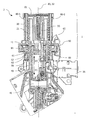
図1は、本発明による駆動部1を備えるコーヒー抽出装置2の側面を示す長手方向断面図を示す。したがって、駆動部1は、まず、雌ねじ11を備える第1の歯車10を包含する。この雌ねじ11は、案内シリンダー20の雄ねじ21上に枢支されているので、回転するとすぐにシリンダー軸22に沿って動くことができる。この場合、シリンダー軸22は第1の歯車10の回転軸を形成する。したがって、第1の歯車は第2の歯車30と係合され、第2の歯車は第1の歯車10を駆動し、その回転軸32は視線方向でシリンダー軸22の下流に位置する。この目的のため、第2の歯車30はやはり、かさ歯車35−1を備えるモータ35によって駆動される。第1の歯車10は、第1の歯車10によってシリンダー軸22に沿って上下に動くことができる抽出ピストン40に連結される。この図では、抽出ピストン40は抽出位置に位置し、すなわち、ピストン40は抽出チャンバ41内に位置するコーヒーに圧力をかける。それにより、抽出ピストン40は、歯車10を封入するハウジング50を通して第1の歯車10に連結される。
FIG. 1 shows a longitudinal section through a side view of a
このハウジング50の第1の歯車10とは反対側の放射方向の振動を防ぐため、第1の歯車10とハウジング50との間に、回転する止め具61から成り、ハウジング50上で具体化され、第1の歯車10の円筒状の付加物62が当接するピボット軸受60が設けられる。その際、第1の歯車10ならびにハウジング50は、シリンダー軸に対して放射方向でシリンダー軸22に沿って案内される。その際、シリンダー軸22に対して放射方向での第1の歯車10およびハウジング50の振動が有効に制動され、それが駆動部の大幅なノイズ低減に結び付く。
In order to prevent radial vibration on the opposite side of the
ハウジング50に対するピストン40の接続は、(例えば、EP0559620B1から知られているような、長方形の断面プロファイルを備える中空体の形態で)相当に高い程度まで振動に敏感であって、より大きな断面をさらに必要とする、現在一般的なプラスチック締結具に代わる金属板70を提供する。
The connection of the
第1の歯車10が、抽出チャンバ41に向かう方向で(すなわち、図1の矢印D1の方向で)シリンダー軸22に沿って雄ねじ21上で動くような形で、回転軸32の周りを回転する場合、円筒状の付加物62の表面積63は、金属板70と接触しており、金属板70を圧迫する。その際、矢印D1の方向の動きに応答して、第1の歯車10がハウジング50に連結される。第1の歯車10が、抽出チャンバ41から離れる方向で(すなわち、矢印D1の方向とは反対に、つまり図1の矢印D2の方向で)シリンダー軸22に沿って雄ねじ21上で動くような形で、回転軸32の周りを回転する場合、抽出チャンバ41から離れる方向に面する第1の歯車10の表面積65は、ハウジング50と接触しており、ハウジング50を押す。その際、矢印D2の方向の動きに応答して、第1の歯車10がハウジング50に連結される。
The
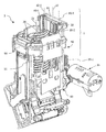
図2および3は、異なる視点から見た図1によるコーヒー抽出装置2を示す。図2および3に示されるように、駆動部1は線形ガイド80を備え、その上でハウジング50が案内シリンダー20に沿った往復運動に応答して案内される。この目的のため、ハウジングは、より詳細に後述するような形で線形ガイド80と係合される。線形ガイド80自体は、2つの案内ロッド80−1および80−1を備え、それらは、理想的には、その曲げ剛性を増加させ、結果としてその固有振動を低減するように、U字形またはH字形の断面プロファイルを包含する。ロッド80−1および80−2は、案内シリンダー20とは反対側で装置2のベース90上で固定的に支持される。ハウジング50のガイドのこの実施形態により、振動に対するその感受性と、したがってその見込まれるノイズの発生とがさらに大幅に低減される。
2 and 3 show the
これは、ガイド80がハウジング50の側面に取り付けられ、そこで第2の歯車30から第1の歯車10への動力伝達が行われる(ここでは目に見えない)という点でさらに支持される。線形ガイド自体の上でのハウジング50のわずかなカントとそれに続く不安定な動きとが除外される。
This is further supported in that the
したがって、第2の歯車30を特に低振動で支持するため、案内ロッド80−1および80−2の上端が延長部81を通じて相互に接続されるような形で具体化される。第2の歯車30の回転軸32は、一方ではこの延長部81上で、他方ではベース90上で支持され、それによって、ガイド80は、この歯車30を振動のない形で吊り下げる目的でも役立つが、これは特に、第2の歯車30の回転軸32が、いずれの場合にも、線形ガイド80または案内ロッド80−1および80−2それぞれに対する規定の距離で、ベース90上ならびに延長部81上の対向する端部上で保持されるためである。その際、第2の歯車30の回転軸32は、線形ガイド80に対する傾斜または曲がりそれぞれに対して特定の有効なやり方で固定される。同時に、ガイド80および第2の歯車30は、特にコンパクトで小型の共通の構造単位を形成し、それは、コーヒー抽出装置2の設置高さに対する負の影響を有さず、すなわち、コーヒー抽出装置の設置高さを増加させない。
Therefore, in order to support the
最後に、図4は、開いたハウジング50に対応する図1のコーヒー抽出装置2の上面図を示す。ハウジング50内で支持される第1の歯車10をやはり見ることができる。第1の歯車10は、第2の歯車30によって回転し、それが次にモータ35によって駆動される。したがって、第1の歯車10は、ハウジング50およびそれに連結された抽出ピストン40とともに、シート面に対して直角の方向で、すなわち案内シリンダー20に沿って動くことができる。
Finally, FIG. 4 shows a top view of the
いずれの場合にも線形ガイド80の案内ロッド80−1または80−2がそれぞれ貫通するフランジ52−1、52−2は、ハウジング50を線形ガイド80上で案内する目的で、一個片の形でハウジングに接続されるようにしてこのハウジング上で具体化される。それにより、案内ロッド80−1および80−2は、いずれの場合にも、溝83−1または83−2をそれぞれ備えるほぼH字形の断面プロファイルを包含し、それらの溝83−1または83−2それぞれの中に、ハウジング50上で具体化される突出部84−1または84−2がそれぞれ係合する。対応する溝83−1および83−2内での突出部84−1および84−2の案内は、したがって、シリンダー軸22に対して放射方向でのハウジングの振動する動きを防ぎ、それによってノイズが低減される。溝83−1、83−2が第2の歯車30の方向に開いているという事実により、第2の歯車30が回転し、第1の歯車10に、したがってハウジング50に力を働かせるとすぐに、対応する突出部84−1、84−2がこの溝に押し込まれる。これは、ハウジング50と線形ガイド80との間の係合の安定化に寄与し、それによって振動の形成が排除される。
In any case, the flanges 52-1 and 52-2 through which the guide rods 80-1 and 80-2 of the
この場合、延長部81は案内ロッド80−1および80−2のそれぞれに強固に接続される。シリンダー軸22に対して放射方向で、各案内ロッド80−1または80−2それぞれとは反対側でのハウジング50の動きをいずれの場合にも防ぐような形で、ハウジング50が線形ガイド80と、または各案内ロッド80−1または80−2それぞれと係合するという事実により、また、第2の歯車30の回転軸32が線形ガイド80または各案内ロッド80−1もしくは80−2それぞれに対して規定の距離で配置されているという事実により、この場合、抽出ピストン40または第1の歯車10それぞれのシリンダー軸22に沿った位置とは独立に、シリンダー軸22または第1の歯車10の回転軸それぞれと、第2の歯車30の回転軸32との間の距離が一定に保たれることが確保される。したがって、シリンダー軸22に沿った(規定の許容差内での)往復運動の間、第1の歯車10は第2の歯車30とは反対側に案内される。
In this case, the
フランジ52−1、52−2の実施形態により、第1の歯車10はさらに、ハウジング50によって完全に封入することができるので、残るノイズの発生が外部に広がることはない。ハウジング50の開口部51は、第1の歯車10と第2の歯車30との間の動作可能な接続に必要なだけの大きさであるように選択されるので、本明細書では防音も実現される。
According to the embodiment of the flanges 52-1 and 52-2, the
第1の歯車10と第2の歯車30との間の速度伝達比が4.0〜4.5であるように選択され、それによって、不安定な回転運動と、不安定な回転運動によって好ましくは励起され得る振動とを防ぐように、第1の歯車10とハウジング50との間の摩擦力を容易に克服するより強力な駆動部が確保されるという点で、さらなるノイズの低減が実現される。
The speed transmission ratio between the
コーヒー抽出装置2は、好ましくは、ハウジングへの振動の伝達を排除するように、防振ゴムを用いるやり方でベース支持部に取り付けることができる。ただし、本明細書では代表的な形でのみ示している駆動部1は、既に相当なノイズ低減を可能にしており、さらに、その構造に関して単純かつコンパクトな形で設計され、したがって費用効率の高いやり方で製造することができる。
The
1 駆動部
2 コーヒー抽出装置
11 雌ねじ
20 案内シリンダー
21 雄ねじ
22 シリンダー軸
30 第2の歯車
32 回転軸
35 モータ
35−1 かさ歯車
40 抽出ピストン
41 抽出チャンバ
50 ハウジング
51 開口部
52−1、52−2 フランジ
60 ピボット軸受
61 回転する止め具
62 円筒状の付加物
63、65 表面積
70 金属板
80 線形ガイド
80−1、80−2 案内ロッド
81 延長部
83−1、83−2 溝
84−1、84−2 突出部
90 ベース
DESCRIPTION OF
Claims (19)
前記第1の歯車(10)を前記シリンダー軸(22)に沿って駆動する目的で、前記第1の歯車(10)と係合する第2の歯車(30)と、
前記第1の歯車(10)が収容されるハウジング(50)と、
前記シリンダー軸(22)に沿って前記第1の歯車(10)とともに動くことができるように前記ハウジング(50)に連結された抽出ピストン(40)とを備える、コーヒー抽出装置(2)用の駆動部(1)であって、
前記駆動部(1)が、前記ハウジング(50)を案内する線形ガイド(80)を備え、前記線形ガイド(80)が、前記シリンダー軸(22)に平行な距離で通っており、かつそれによって、前記シリンダー軸(22)に対して放射方向での前記線形ガイド(80)とは反対側への前記ハウジング(50)の動きを防ぐような形で前記ハウジング(50)が係合され、
前記第2の歯車(30)の回転軸(32)が、前記線形ガイド(80)に対して規定の距離で配置されることを特徴とする、駆動部(1)。 A first gear (10) comprising an internal thread (11), pivotally supported on the external thread (21) of the guide cylinder (20) through the internal thread (11), thereby responding to the rotation of the guide cylinder A first gear (10) capable of moving along a cylinder axis (22) of (20);
A second gear (30) engaged with the first gear (10) for the purpose of driving the first gear (10) along the cylinder axis (22);
A housing (50) in which the first gear (10) is housed;
An extraction piston (40) connected to the housing (50) so as to be able to move with the first gear (10) along the cylinder axis (22). A drive unit (1),
The drive (1) comprises a linear guide (80) for guiding the housing (50), the linear guide (80) being passed through a distance parallel to the cylinder axis (22), and thereby The housing (50) is engaged in a manner that prevents movement of the housing (50) in a radial direction opposite to the linear guide (80) relative to the cylinder axis (22);
Drive unit (1), characterized in that the rotation shaft (32) of the second gear (30) is arranged at a specified distance with respect to the linear guide (80).
Applications Claiming Priority (2)
| Application Number | Priority Date | Filing Date | Title |
|---|---|---|---|
| EP08405303A EP2196115A1 (en) | 2008-12-12 | 2008-12-12 | Drive for a coffee brewing device and coffee brewing device |
| EP08405303.2 | 2008-12-12 |
Publications (2)
| Publication Number | Publication Date |
|---|---|
| JP2010137055A JP2010137055A (en) | 2010-06-24 |
| JP4922385B2 true JP4922385B2 (en) | 2012-04-25 |
Family
ID=40557338
Family Applications (1)
| Application Number | Title | Priority Date | Filing Date |
|---|---|---|---|
| JP2009279315A Expired - Fee Related JP4922385B2 (en) | 2008-12-12 | 2009-12-09 | Drive unit for coffee extraction device and coffee extraction device |
Country Status (15)
| Country | Link |
|---|---|
| US (1) | US8733232B2 (en) |
| EP (2) | EP2196115A1 (en) |
| JP (1) | JP4922385B2 (en) |
| KR (1) | KR101216208B1 (en) |
| CN (1) | CN101744533B (en) |
| AT (1) | ATE533390T1 (en) |
| AU (1) | AU2009225330B2 (en) |
| BR (1) | BRPI0904812A2 (en) |
| CA (1) | CA2683665C (en) |
| HK (1) | HK1143513A1 (en) |
| MX (1) | MX2009013636A (en) |
| MY (1) | MY145858A (en) |
| PT (1) | PT2196116E (en) |
| SG (1) | SG162656A1 (en) |
| ZA (2) | ZA200907089B (en) |
Families Citing this family (17)
| Publication number | Priority date | Publication date | Assignee | Title |
|---|---|---|---|---|
| FR2960757B1 (en) * | 2010-06-08 | 2012-06-15 | Seb Sa | INFUSION DEVICE WITH CONTROL OF THE MILLING QUANTITY AND COFFEE MACHINE COMPRISING SUCH A DEVICE |
| EP2397054A1 (en) | 2010-06-15 | 2011-12-21 | Jura Elektroapparate AG | Brewing device with a coffee reheater |
| KR20130095757A (en) * | 2010-08-27 | 2013-08-28 | 네스텍 소시에테아노님 | Controlled motorized brewing unit |
| EP2543291A1 (en) * | 2011-07-08 | 2013-01-09 | Koninklijke Philips Electronics N.V. | Brewing unit with a water heater |
| DE102010063943A1 (en) * | 2010-12-22 | 2012-06-28 | BSH Bosch und Siemens Hausgeräte GmbH | Coffee machine with encapsulated drive |
| US9664264B2 (en) * | 2011-01-03 | 2017-05-30 | Nestec S.A. | Motorized beverage machine with mechanical transmission |
| RU2583300C2 (en) * | 2011-01-17 | 2016-05-10 | Сантори Беверидж Энд Фуд Лимитед | Method of producing coffee extract |
| EP2570056A1 (en) | 2011-09-13 | 2013-03-20 | Jura Elektroapparate AG | Method for creating a coffee drink and coffee machine for carrying out the method |
| EP2599412A1 (en) * | 2011-12-01 | 2013-06-05 | Nestec S.A. | A beverage preparation machine |
| CN103735169A (en) * | 2012-10-17 | 2014-04-23 | 苏州工业园区咖乐美电器有限公司 | Device for brewing coffee |
| DE102012220753B4 (en) * | 2012-11-14 | 2019-01-17 | BSH Hausgeräte GmbH | Coffee machine with removable spindle brewing unit |
| KR200472696Y1 (en) * | 2012-11-14 | 2014-05-15 | 이상래 | A nozzel structure of the coffee extractor |
| TWM452540U (en) * | 2012-12-27 | 2013-05-01 | Timotion Technology Co Ltd | Electric cylinder and rapid release mechanism thereof |
| KR101489809B1 (en) * | 2013-08-06 | 2015-02-04 | 주식회사 화인에스앤씨 | The automatic espresso coffee machine with smart extracting device |
| PT109304B (en) * | 2016-04-07 | 2021-02-26 | Novadelta - Comércio E Indústria De Cafés, S.A. | EXTRACTION DEVICE WITH ADAPTED COLLECTION CHAMBER |
| CN106724840A (en) * | 2016-12-21 | 2017-05-31 | 苏州咖博士咖啡系统科技有限公司 | A kind of beverage pouring and boiling device |
| CN110326972B (en) * | 2019-06-14 | 2021-08-10 | 东南大学 | Automatic clamping and aligning device for water receiving cup of electric kettle and control method thereof |
Family Cites Families (9)
| Publication number | Priority date | Publication date | Assignee | Title |
|---|---|---|---|---|
| CA2092911C (en) * | 1991-07-30 | 2000-11-21 | Andre Lussi | Brewing device for a coffee machine and method of producing coffee |
| ATE118678T1 (en) * | 1992-03-02 | 1995-03-15 | Jura Elektroapparate Ag | BREWING DEVICE, PARTICULARLY FOR A COFFEE MACHINE. |
| CN2498959Y (en) * | 2001-08-20 | 2002-07-10 | 美国·灿坤公司 | Pouring and regulating device for electric coffee machine |
| US6453800B1 (en) * | 2001-09-10 | 2002-09-24 | Tsann Kuen Usa Inc. | Brewing apparatus for electric coffee maker |
| EP1483992B1 (en) * | 2002-03-08 | 2005-07-27 | Azkoyen Industrial, S.A. | Automated coffee brewing device |
| DE202004018776U1 (en) * | 2004-12-04 | 2005-02-10 | Eugster/Frismag Ag | Brewing head of an espresso machine |
| US8039033B2 (en) * | 2005-04-22 | 2011-10-18 | Coffee Innovation Group B.V. | Method and device for preparing coffee |
| DE102005049624A1 (en) * | 2005-10-14 | 2007-07-12 | Niro-Plan Ag | coffee machine |
| CN100584256C (en) * | 2007-08-10 | 2010-01-27 | 李行 | Coffee infusing device |
-
2008
- 2008-12-12 EP EP08405303A patent/EP2196115A1/en not_active Withdrawn
-
2009
- 2009-10-12 ZA ZA2009/07089A patent/ZA200907089B/en unknown
- 2009-10-12 ZA ZA200907039A patent/ZA200907039B/en unknown
- 2009-10-14 AU AU2009225330A patent/AU2009225330B2/en active Active
- 2009-10-28 CA CA2683665A patent/CA2683665C/en active Active
- 2009-11-10 KR KR1020090108041A patent/KR101216208B1/en active IP Right Grant
- 2009-11-11 CN CN200910180168.4A patent/CN101744533B/en active Active
- 2009-11-13 MY MYPI20094833A patent/MY145858A/en unknown
- 2009-11-13 SG SG200907556-5A patent/SG162656A1/en unknown
- 2009-12-05 AT AT09015096T patent/ATE533390T1/en active
- 2009-12-05 EP EP09015096A patent/EP2196116B1/en active Active
- 2009-12-05 PT PT09015096T patent/PT2196116E/en unknown
- 2009-12-08 US US12/633,165 patent/US8733232B2/en active Active
- 2009-12-09 JP JP2009279315A patent/JP4922385B2/en not_active Expired - Fee Related
- 2009-12-09 BR BRPI0904812-0A patent/BRPI0904812A2/en not_active IP Right Cessation
- 2009-12-14 MX MX2009013636A patent/MX2009013636A/en active IP Right Grant
-
2010
- 2010-11-01 HK HK10110216.5A patent/HK1143513A1/en unknown
Also Published As
| Publication number | Publication date |
|---|---|
| HK1143513A1 (en) | 2011-01-07 |
| MY145858A (en) | 2012-05-15 |
| BRPI0904812A2 (en) | 2011-02-08 |
| EP2196116B1 (en) | 2011-11-16 |
| CA2683665A1 (en) | 2010-06-12 |
| US8733232B2 (en) | 2014-05-27 |
| ATE533390T1 (en) | 2011-12-15 |
| ZA200907089B (en) | 2010-07-28 |
| CN101744533A (en) | 2010-06-23 |
| ZA200907039B (en) | 2010-07-28 |
| EP2196115A1 (en) | 2010-06-16 |
| MX2009013636A (en) | 2010-08-09 |
| CN101744533B (en) | 2012-07-18 |
| CA2683665C (en) | 2011-06-14 |
| PT2196116E (en) | 2012-01-12 |
| EP2196116A1 (en) | 2010-06-16 |
| KR20100068187A (en) | 2010-06-22 |
| KR101216208B1 (en) | 2012-12-28 |
| AU2009225330B2 (en) | 2011-10-27 |
| US20100147091A1 (en) | 2010-06-17 |
| JP2010137055A (en) | 2010-06-24 |
| SG162656A1 (en) | 2010-07-29 |
| AU2009225330A1 (en) | 2010-07-01 |
Similar Documents
| Publication | Publication Date | Title |
|---|---|---|
| JP4922385B2 (en) | Drive unit for coffee extraction device and coffee extraction device | |
| JP3833757B2 (en) | Reciprocating drive mechanism | |
| JP4969559B2 (en) | Damper device for moving parts of furniture | |
| AU2007223472B2 (en) | Electrical power tool | |
| JP5041575B2 (en) | Impact tool | |
| US20210283389A1 (en) | Tattoo device with motor having built-in motion conversion member | |
| EP1602826B1 (en) | Pump drive | |
| JP7060571B2 (en) | How to support a differential impulse conveyor and a reciprocating structure | |
| JP2014234887A (en) | Balancer device | |
| JP2017198287A (en) | Drive transmission mechanism and machine device utilizing drive transmission mechanism | |
| JP7255992B2 (en) | Case bearing fixing structure and bearing fixing method to the case | |
| KR200477328Y1 (en) | Electric Breast Pump vacuum creation Apparatuse | |
| JP5281555B2 (en) | Tube pump | |
| JP2014015162A (en) | Rotary actuator, and electric retractable door mirror using the same | |
| EP2792342A1 (en) | Massage apparatus | |
| JP5327726B2 (en) | Impact tool | |
| JP6945799B2 (en) | Rear wheel steering device | |
| CN112867572A (en) | High-pressure cleaning machine | |
| RU2346434C2 (en) | Petrov's reel | |
| KR101153727B1 (en) | Cylinder Barrel having Structure for Reducing SizeCylinder Barrel having Structure for Reducing Size and Weight and Weight | |
| JP5717457B2 (en) | Lens barrel and digital camera | |
| JP2005210810A (en) | Motor comprising eccentric output | |
| JP2012030651A (en) | Rack and pinion mechanism, and steering device | |
| JP2016044740A (en) | Telescopic actuator | |
| JP2014110861A (en) | Sewing machine |
Legal Events
| Date | Code | Title | Description |
|---|---|---|---|
| TRDD | Decision of grant or rejection written | ||
| A01 | Written decision to grant a patent or to grant a registration (utility model) |
Free format text: JAPANESE INTERMEDIATE CODE: A01 Effective date: 20120117 |
|
| A01 | Written decision to grant a patent or to grant a registration (utility model) |
Free format text: JAPANESE INTERMEDIATE CODE: A01 |
|
| A61 | First payment of annual fees (during grant procedure) |
Free format text: JAPANESE INTERMEDIATE CODE: A61 Effective date: 20120203 |
|
| R150 | Certificate of patent or registration of utility model |
Free format text: JAPANESE INTERMEDIATE CODE: R150 |
|
| FPAY | Renewal fee payment (event date is renewal date of database) |
Free format text: PAYMENT UNTIL: 20150210 Year of fee payment: 3 |
|
| LAPS | Cancellation because of no payment of annual fees |