EP2196102B1 - Button as well as button body and fixture for such a button - Google Patents
Button as well as button body and fixture for such a button Download PDFInfo
- Publication number
- EP2196102B1 EP2196102B1 EP08021555.1A EP08021555A EP2196102B1 EP 2196102 B1 EP2196102 B1 EP 2196102B1 EP 08021555 A EP08021555 A EP 08021555A EP 2196102 B1 EP2196102 B1 EP 2196102B1
- Authority
- EP
- European Patent Office
- Prior art keywords
- button
- fixture
- button body
- protrusion
- support
- Prior art date
- Legal status (The legal status is an assumption and is not a legal conclusion. Google has not performed a legal analysis and makes no representation as to the accuracy of the status listed.)
- Active
Links
- 239000004744 fabric Substances 0.000 description 6
- 239000000463 material Substances 0.000 description 3
- 239000002184 metal Substances 0.000 description 2
- 230000004323 axial length Effects 0.000 description 1
- 230000004048 modification Effects 0.000 description 1
- 238000012986 modification Methods 0.000 description 1
- 230000002093 peripheral effect Effects 0.000 description 1
- 230000035939 shock Effects 0.000 description 1
- 229920003002 synthetic resin Polymers 0.000 description 1
- 239000000057 synthetic resin Substances 0.000 description 1
Images


Classifications
-
- A—HUMAN NECESSITIES
- A44—HABERDASHERY; JEWELLERY
- A44B—BUTTONS, PINS, BUCKLES, SLIDE FASTENERS, OR THE LIKE
- A44B1/00—Buttons
- A44B1/18—Buttons adapted for special ways of fastening
- A44B1/28—Buttons adapted for special ways of fastening with shank and counterpiece
- A44B1/34—Buttons adapted for special ways of fastening with shank and counterpiece with snap-action counterpiece
-
- Y—GENERAL TAGGING OF NEW TECHNOLOGICAL DEVELOPMENTS; GENERAL TAGGING OF CROSS-SECTIONAL TECHNOLOGIES SPANNING OVER SEVERAL SECTIONS OF THE IPC; TECHNICAL SUBJECTS COVERED BY FORMER USPC CROSS-REFERENCE ART COLLECTIONS [XRACs] AND DIGESTS
- Y10—TECHNICAL SUBJECTS COVERED BY FORMER USPC
- Y10T—TECHNICAL SUBJECTS COVERED BY FORMER US CLASSIFICATION
- Y10T24/00—Buckles, buttons, clasps, etc.
- Y10T24/36—Button with fastener
- Y10T24/3628—Integral or rigid stud
-
- Y—GENERAL TAGGING OF NEW TECHNOLOGICAL DEVELOPMENTS; GENERAL TAGGING OF CROSS-SECTIONAL TECHNOLOGIES SPANNING OVER SEVERAL SECTIONS OF THE IPC; TECHNICAL SUBJECTS COVERED BY FORMER USPC CROSS-REFERENCE ART COLLECTIONS [XRACs] AND DIGESTS
- Y10—TECHNICAL SUBJECTS COVERED BY FORMER USPC
- Y10T—TECHNICAL SUBJECTS COVERED BY FORMER US CLASSIFICATION
- Y10T24/00—Buckles, buttons, clasps, etc.
- Y10T24/36—Button with fastener
- Y10T24/3651—Separable
-
- Y—GENERAL TAGGING OF NEW TECHNOLOGICAL DEVELOPMENTS; GENERAL TAGGING OF CROSS-SECTIONAL TECHNOLOGIES SPANNING OVER SEVERAL SECTIONS OF THE IPC; TECHNICAL SUBJECTS COVERED BY FORMER USPC CROSS-REFERENCE ART COLLECTIONS [XRACs] AND DIGESTS
- Y10—TECHNICAL SUBJECTS COVERED BY FORMER USPC
- Y10T—TECHNICAL SUBJECTS COVERED BY FORMER US CLASSIFICATION
- Y10T24/00—Buckles, buttons, clasps, etc.
- Y10T24/36—Button with fastener
- Y10T24/3683—Button with cavity for friction grip fastener
-
- Y—GENERAL TAGGING OF NEW TECHNOLOGICAL DEVELOPMENTS; GENERAL TAGGING OF CROSS-SECTIONAL TECHNOLOGIES SPANNING OVER SEVERAL SECTIONS OF THE IPC; TECHNICAL SUBJECTS COVERED BY FORMER USPC CROSS-REFERENCE ART COLLECTIONS [XRACs] AND DIGESTS
- Y10—TECHNICAL SUBJECTS COVERED BY FORMER USPC
- Y10T—TECHNICAL SUBJECTS COVERED BY FORMER US CLASSIFICATION
- Y10T24/00—Buckles, buttons, clasps, etc.
- Y10T24/36—Button with fastener
- Y10T24/3685—Button with shank for friction grip fastener
Definitions
- the present invention relates to a button comprising a button body and a fixture for fixing said button body to a support from the opposite side to the button body with the support therebetween, said button body having an insert hole defined by a wall, for the fixture to be inserted therein, and at least one protrusion for fixing on said support.
- Buttons of the above-mentioned kind are known, e.g. from EP 1 541 050 A1 .
- conventional buttons when the fixture is inserted into the insert hole the insert hole and thereby the wall defining said hole is urged to expand, since the part of the fixture to be inserted has a larger outer diameter as compared to the inner diameter of the insert hole.
- the conventional button With the conventional button, however, there is strong resistance against such an expansion because said protrusion is positioned on said wall defining said insert hole. In other words, if said wall is to be expanded, said protrusion must be expanded (lengthened) as well.
- the wall defining the insert hole can be expanded when the fixture is inserted into the insert hole, without simultaneously expanding the protrusion, resulting in that the overall resistance against said extension is reduced.
- the wall defining the insert hole can be expanded when the fixture is inserted into the insert hole, without simultaneously expanding the protrusion, resulting in that the overall resistance against said extension is reduced.
- the outer diameter of said insert hole defining wall increases in at least one axial section in the direction from a lower side of the button body facing the support to an upper side of the button body.
- the button body may have any contour, it is preferred that the outer contour of the insert hole defining wall is conical in at least one axial section in the direction from a lower side of the button body facing the support to an upper side of the button body.
- said protrusion has a circular cross section. This results in advantages during production.
- said protrusion preferably has a conical head portion.
- the cross section of the insert hole is increasing, particularly stepwise, from a lower side of the button body facing the support to an upper side of the button body. This makes the connection stronger.
- the depth of the gap essentially corresponds to the axial length of the lowest (and smallest) part of the insert hole or is even larger, because in this part of the button body the expansion of the wall is expected to be largest.
- the fixture has a least one protrusion for fixing on said support.
- Said protrusion preferably has pyramid form.
- said protrusion of said fixture and said protrusion of said button body cooperate to clasp said support when mounted. It is clear that they need to have certain positions relative to one another.
- said protrusion of said fixture is positioned radially inside or radially outside said protrusion of said button body, when mounted. Thereby, radial or lateral movement is prevented, particularly with view to thin material supports.
- means for preventing the fixture from rotating relative to the button body is provided.
- the protrusion of the button body on the one hand and the protrusion of the fixture on the other hand are mounted in the correct relative position to guarantee the above functions.
- said rotation-preventing means comprises at least one protrusion, particularly a rib or a tread.
- the present invention does not refer to the above button only, but also to a button body and to a fixture of such a button.
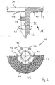
- a button body 10 includes a collar 12, a shaft 14 and an insert hole 16 for a fixture 18 to be inserted therein.
- Button body 10 is made of a material allowing to expand the external form of shaft 14 to be out of position when fixture 18 is inserted into insert hole 16, such as synthetic resin as used in this embodiment.
- Insert hole 16 has a step-like form, with the inner diameter becoming smaller step by step from an end face facing fixture 18.
- insert hole 16 including a first hole 16A, a second hole 16B with the inner diameter being smaller than first hole 16A, and a third hole 16C with the inner diameter being smaller than that of second hole 16B are arranged sequentially on the three steps as described above.
- Protrusions 20, 22, 24, 26 are formed integrally with shaft 14. They have circular cross sections and a conical head portion. Between said protrusions 20, 22, 24, 26 and a wall 28 defining insert hole 16, there is a gap 30, allowing wall 28 to expand when insert 18 is inserted into insert hole 16.
- Wall 28 has a conical outer contour where it defines third insert hole 16C and partly where it defines second insert hole 16B.
- Fixture 18 includes an insert shaft 32 to be inserted into insert hole 16 of button body 10, and a flange 34 integrally formed on a base end side of insert shaft 32.
- fixture 18 is made of metal.
- Insert shaft 32 includes a guide part 36 having a conical tip and also having a round cross section perpendicular to a center line of insert shaft 32 and an engagement 38. Insert shaft 32 has an outer diameter that is larger than an inner diameter of second hole 16B of insert hole 16. For instance, when an inner diameter of second hole 16B is 15 mm and an outer diameter of insert shaft 32 is 21 mm, the inner diameter of hole 16B expands by the difference, namely by 6 mm when fixture 18 is mounted to button body 10.
- protrusions 40, 42, 44, 46, 48, 50 are formed, each having a form like a quadrangular pyramid, and arranged to cooperate with protrusions 20, 22, 24, 26, respectively, in order to therebetween clasp a support (not shown in the drawings) to which the button is to be fixed. Furthermore, on said inner surface of flange 34 are ring-formed concave-convex portions 47 which are provided concentrically around insert shaft 32, one of which being referred to as number 52.
- the fabric is held between the protruding end face of wall 28 and the inner surface of flange 34. Furthermore, said protrusions serve for holding said fabric and for preventing lateral or radial movement of fixture 18 relative to button body 10.
- a plurality of projected treads 54 is provided on the outer peripheral surface of insert shaft 32 with a specified space therebetween along the axial direction. With this configuration, projected treads 54 crimp into insert hole 16 of button body 10, preventing rotational movement of fixture 18 relative to button body 10.
- button body 10 can be provided with a cap 56 made of metal. However, this is optional.
- buttons for jeans are not limited to buttons for jeans, but can be used for other supports, such as other types of garments or for other than garments.
Landscapes
- Slide Fasteners, Snap Fasteners, And Hook Fasteners (AREA)
- Hooks, Suction Cups, And Attachment By Adhesive Means (AREA)
- Switches With Compound Operations (AREA)
- Insertion Pins And Rivets (AREA)
Priority Applications (4)
| Application Number | Priority Date | Filing Date | Title |
|---|---|---|---|
| EP08021555.1A EP2196102B1 (en) | 2008-12-11 | 2008-12-11 | Button as well as button body and fixture for such a button |
| BRPI0905296-8A BRPI0905296A2 (pt) | 2008-12-11 | 2009-12-10 | botão e corpo do botão e guarnição para o botão |
| US12/635,891 US8522403B2 (en) | 2008-12-11 | 2009-12-11 | Button as well as button body and fixture for such a button |
| CN2009102524759A CN101791166B (zh) | 2008-12-11 | 2009-12-11 | 钮扣、该钮扣的钮扣主体和固定件 |
Applications Claiming Priority (1)
| Application Number | Priority Date | Filing Date | Title |
|---|---|---|---|
| EP08021555.1A EP2196102B1 (en) | 2008-12-11 | 2008-12-11 | Button as well as button body and fixture for such a button |
Publications (2)
| Publication Number | Publication Date |
|---|---|
| EP2196102A1 EP2196102A1 (en) | 2010-06-16 |
| EP2196102B1 true EP2196102B1 (en) | 2013-05-01 |
Family
ID=40551965
Family Applications (1)
| Application Number | Title | Priority Date | Filing Date |
|---|---|---|---|
| EP08021555.1A Active EP2196102B1 (en) | 2008-12-11 | 2008-12-11 | Button as well as button body and fixture for such a button |
Country Status (4)
| Country | Link |
|---|---|
| US (1) | US8522403B2 (zh) |
| EP (1) | EP2196102B1 (zh) |
| CN (1) | CN101791166B (zh) |
| BR (1) | BRPI0905296A2 (zh) |
Families Citing this family (5)
| Publication number | Priority date | Publication date | Assignee | Title |
|---|---|---|---|---|
| NL1038870C2 (nl) * | 2011-06-14 | 2012-12-17 | Babouche Schoenen B V | Stelsel omvattende een knoop, een bevestigingsorgaan en een sierelement, alsmede een knoop of een sierelement als deel van dit stelsel, alsmede een kledingsstuk, voorzien van een dergelijke knoop. |
| CN106687004B (zh) * | 2014-09-08 | 2019-06-28 | Ykk株式会社 | 铆钉 |
| WO2016161476A1 (en) * | 2015-04-08 | 2016-10-13 | Williams Lindsay Joseph | Button carrier / adaptor assembly and developed buttonhole |
| US10066658B1 (en) * | 2017-08-01 | 2018-09-04 | Ykk Corporation Of America | Non-rotatable fastener assembly and associated methods |
| CN109259388B (zh) * | 2018-09-25 | 2021-05-14 | 李森瑞 | 一种多套式纽扣及其使用方法 |
Family Cites Families (7)
| Publication number | Priority date | Publication date | Assignee | Title |
|---|---|---|---|---|
| US1646053A (en) * | 1925-02-16 | 1927-10-18 | Universal Button Fastening & B | Button fastening |
| US2299494A (en) * | 1941-05-01 | 1942-10-20 | Patent Button Co | Plastic button |
| FR2633811B1 (fr) * | 1988-07-11 | 1995-05-24 | Papazian Zareh | Bouton a fixation rapide et son dispositif de mise en place |
| US5189762A (en) * | 1991-10-09 | 1993-03-02 | Giancaspro Joseph C | Removable threadless button apparatus |
| ITPD940146A1 (it) * | 1994-08-05 | 1996-02-05 | Riccardo Candotti | Bottone per confezioni |
| US6266853B1 (en) * | 1999-09-24 | 2001-07-31 | Wen-Lung Ho | Non-rotatable enclosing buckle of fabric article |
| JP4095858B2 (ja) | 2002-08-01 | 2008-06-04 | Ykk株式会社 | ボタン |
-
2008
- 2008-12-11 EP EP08021555.1A patent/EP2196102B1/en active Active
-
2009
- 2009-12-10 BR BRPI0905296-8A patent/BRPI0905296A2/pt not_active IP Right Cessation
- 2009-12-11 US US12/635,891 patent/US8522403B2/en active Active
- 2009-12-11 CN CN2009102524759A patent/CN101791166B/zh active Active
Also Published As
| Publication number | Publication date |
|---|---|
| US20100146741A1 (en) | 2010-06-17 |
| BRPI0905296A2 (pt) | 2011-03-22 |
| CN101791166A (zh) | 2010-08-04 |
| EP2196102A1 (en) | 2010-06-16 |
| US8522403B2 (en) | 2013-09-03 |
| CN101791166B (zh) | 2012-07-04 |
Similar Documents
| Publication | Publication Date | Title |
|---|---|---|
| KR850000877Y1 (ko) | 단추 | |
| EP2196102B1 (en) | Button as well as button body and fixture for such a button | |
| JP5540003B2 (ja) | ボタン取付用上金型 | |
| US8393058B2 (en) | Clip | |
| US7251865B2 (en) | Button | |
| CN105339685A (zh) | 推入式紧固件 | |
| EP1143157A1 (en) | Water-proof grommet | |
| JP2005315369A (ja) | クリップ | |
| JP2006207607A (ja) | クリップ | |
| JP5313359B2 (ja) | ボタン取付方法、ボタン取付システム、及びボタン取付用上金型 | |
| JP4137292B2 (ja) | アンダーカットアンカー | |
| US20150096156A1 (en) | Press-stud | |
| KR102183351B1 (ko) | 스냅 파스너의 수형 부재 및 스냅 파스너 | |
| JP6088231B2 (ja) | ホールプラグ | |
| JP6364550B2 (ja) | ボタンバック及びボタン | |
| JP2008111498A (ja) | クリップ | |
| JP3223557U (ja) | かしめボタン | |
| JP4401811B2 (ja) | 装飾ボタン | |
| WO2005070247A2 (en) | Swivel tack button, particularly for items of clothing such as jeans or the like, with very simple assembly and application | |
| US11213085B1 (en) | Accent feather holder for plume socket cup and method of using same | |
| WO2024134899A1 (ja) | ボタン部材 | |
| US8905654B2 (en) | Network camera | |
| US10011144B2 (en) | Cap | |
| JP2004187916A (ja) | ハトメ | |
| JP2005137796A (ja) | 椅子における脚カバーの取付構造 |
Legal Events
| Date | Code | Title | Description |
|---|---|---|---|
| PUAI | Public reference made under article 153(3) epc to a published international application that has entered the european phase |
Free format text: ORIGINAL CODE: 0009012 |
|
| AK | Designated contracting states |
Kind code of ref document: A1 Designated state(s): AT BE BG CH CY CZ DE DK EE ES FI FR GB GR HR HU IE IS IT LI LT LU LV MC MT NL NO PL PT RO SE SI SK TR |
|
| AX | Request for extension of the european patent |
Extension state: AL BA MK RS |
|
| 17P | Request for examination filed |
Effective date: 20101216 |
|
| AKX | Designation fees paid |
Designated state(s): DE GB IT |
|
| 17Q | First examination report despatched |
Effective date: 20110216 |
|
| 17Q | First examination report despatched |
Effective date: 20120904 |
|
| GRAP | Despatch of communication of intention to grant a patent |
Free format text: ORIGINAL CODE: EPIDOSNIGR1 |
|
| GRAS | Grant fee paid |
Free format text: ORIGINAL CODE: EPIDOSNIGR3 |
|
| GRAA | (expected) grant |
Free format text: ORIGINAL CODE: 0009210 |
|
| AK | Designated contracting states |
Kind code of ref document: B1 Designated state(s): DE GB IT |
|
| REG | Reference to a national code |
Ref country code: GB Ref legal event code: FG4D |
|
| REG | Reference to a national code |
Ref country code: DE Ref legal event code: R096 Ref document number: 602008024215 Country of ref document: DE Effective date: 20130627 |
|
| PLBE | No opposition filed within time limit |
Free format text: ORIGINAL CODE: 0009261 |
|
| STAA | Information on the status of an ep patent application or granted ep patent |
Free format text: STATUS: NO OPPOSITION FILED WITHIN TIME LIMIT |
|
| 26N | No opposition filed |
Effective date: 20140204 |
|
| REG | Reference to a national code |
Ref country code: DE Ref legal event code: R097 Ref document number: 602008024215 Country of ref document: DE Effective date: 20140204 |
|
| GBPC | Gb: european patent ceased through non-payment of renewal fee |
Effective date: 20131211 |
|
| PG25 | Lapsed in a contracting state [announced via postgrant information from national office to epo] |
Ref country code: GB Free format text: LAPSE BECAUSE OF NON-PAYMENT OF DUE FEES Effective date: 20131211 |
|
| P01 | Opt-out of the competence of the unified patent court (upc) registered |
Effective date: 20230428 |
|
| PGFP | Annual fee paid to national office [announced via postgrant information from national office to epo] |
Ref country code: DE Payment date: 20241029 Year of fee payment: 17 |
|
| PGFP | Annual fee paid to national office [announced via postgrant information from national office to epo] |
Ref country code: IT Payment date: 20241112 Year of fee payment: 17 |