EP2194276A2 - Zweiwellige Vakuumpumpe - Google Patents
Zweiwellige Vakuumpumpe Download PDFInfo
- Publication number
- EP2194276A2 EP2194276A2 EP09014529A EP09014529A EP2194276A2 EP 2194276 A2 EP2194276 A2 EP 2194276A2 EP 09014529 A EP09014529 A EP 09014529A EP 09014529 A EP09014529 A EP 09014529A EP 2194276 A2 EP2194276 A2 EP 2194276A2
- Authority
- EP
- European Patent Office
- Prior art keywords
- shaft
- piston
- vacuum pump
- release structure
- pistons
- Prior art date
- Legal status (The legal status is an assumption and is not a legal conclusion. Google has not performed a legal analysis and makes no representation as to the accuracy of the status listed.)
- Granted
Links
Images


Classifications
-
- F—MECHANICAL ENGINEERING; LIGHTING; HEATING; WEAPONS; BLASTING
- F04—POSITIVE - DISPLACEMENT MACHINES FOR LIQUIDS; PUMPS FOR LIQUIDS OR ELASTIC FLUIDS
- F04C—ROTARY-PISTON, OR OSCILLATING-PISTON, POSITIVE-DISPLACEMENT MACHINES FOR LIQUIDS; ROTARY-PISTON, OR OSCILLATING-PISTON, POSITIVE-DISPLACEMENT PUMPS
- F04C18/00—Rotary-piston pumps specially adapted for elastic fluids
- F04C18/08—Rotary-piston pumps specially adapted for elastic fluids of intermeshing-engagement type, i.e. with engagement of co-operating members similar to that of toothed gearing
- F04C18/12—Rotary-piston pumps specially adapted for elastic fluids of intermeshing-engagement type, i.e. with engagement of co-operating members similar to that of toothed gearing of other than internal-axis type
- F04C18/126—Rotary-piston pumps specially adapted for elastic fluids of intermeshing-engagement type, i.e. with engagement of co-operating members similar to that of toothed gearing of other than internal-axis type with radially from the rotor body extending elements, not necessarily co-operating with corresponding recesses in the other rotor, e.g. lobes, Roots type
-
- F—MECHANICAL ENGINEERING; LIGHTING; HEATING; WEAPONS; BLASTING
- F04—POSITIVE - DISPLACEMENT MACHINES FOR LIQUIDS; PUMPS FOR LIQUIDS OR ELASTIC FLUIDS
- F04C—ROTARY-PISTON, OR OSCILLATING-PISTON, POSITIVE-DISPLACEMENT MACHINES FOR LIQUIDS; ROTARY-PISTON, OR OSCILLATING-PISTON, POSITIVE-DISPLACEMENT PUMPS
- F04C28/00—Control of, monitoring of, or safety arrangements for, pumps or pumping installations specially adapted for elastic fluids
- F04C28/28—Safety arrangements; Monitoring
-
- F—MECHANICAL ENGINEERING; LIGHTING; HEATING; WEAPONS; BLASTING
- F04—POSITIVE - DISPLACEMENT MACHINES FOR LIQUIDS; PUMPS FOR LIQUIDS OR ELASTIC FLUIDS
- F04C—ROTARY-PISTON, OR OSCILLATING-PISTON, POSITIVE-DISPLACEMENT MACHINES FOR LIQUIDS; ROTARY-PISTON, OR OSCILLATING-PISTON, POSITIVE-DISPLACEMENT PUMPS
- F04C29/00—Component parts, details or accessories of pumps or pumping installations, not provided for in groups F04C18/00 - F04C28/00
- F04C29/0042—Driving elements, brakes, couplings, transmissions specially adapted for pumps
- F04C29/005—Means for transmitting movement from the prime mover to driven parts of the pump, e.g. clutches, couplings, transmissions
- F04C29/0071—Couplings between rotors and input or output shafts acting by interengaging or mating parts, i.e. positive coupling of rotor and shaft
-
- F—MECHANICAL ENGINEERING; LIGHTING; HEATING; WEAPONS; BLASTING
- F04—POSITIVE - DISPLACEMENT MACHINES FOR LIQUIDS; PUMPS FOR LIQUIDS OR ELASTIC FLUIDS
- F04C—ROTARY-PISTON, OR OSCILLATING-PISTON, POSITIVE-DISPLACEMENT MACHINES FOR LIQUIDS; ROTARY-PISTON, OR OSCILLATING-PISTON, POSITIVE-DISPLACEMENT PUMPS
- F04C2240/00—Components
- F04C2240/20—Rotors
Definitions
- the invention relates to a vacuum pump according to the preamble of the first claim.
- Two-shaft vacuum pumps have become indispensable in many industrial applications. Examples of such applications include metallurgy, vacuum drying and chemical engineering.
- the basic structure of these vacuum pumps is to operate two shafts in opposite directions at the same speed. This is ensured for example by a mechanical synchromesh. On these shafts are provided pistons which cooperate, trapping gas volumes and transferring them from the pump inlet to the pump outlet.
- twin-shaft vacuum pumps such as claw, screw or Roots pumps
- a moment is introduced into the bearings when the pistons are touched.
- the core idea of the invention is to provide a release structure between the point of moment introduction, namely the contacting piston surfaces, and the shaft bearings. This interrupts the flow of torque by allowing a rotation of the piston and shaft relative to each other. Therefore, the moments are transmitted to the bearings to a much reduced extent and to a lesser extent to the housing. As a result, the safety is significantly increased when touching the piston.
- shaft and piston are made in one piece or materially connected to each other. Again, it is advantageous because structurally simple and inexpensive to make the transition from shaft to piston so that gives in a touch of the piston, this transition.
- a deformation zone in at least one of the pistons as a development of the invention causes a further increase in safety.
- additional kinetic energy is dissipated by plastic deformation, so that the moments transmitted to the bearings are additionally reduced.
- FIG. 1 A section along the axes of a Roots vacuum pump shows FIG. 1 ,
- the pump chamber 2 In the housing 1 of the vacuum pump is the pump chamber 2. This is penetrated by a first shaft 10 and a second shaft 14. In the direction of the shaft axes, it is limited by a first end shield 4 and a second end shield 5.
- a first piston 12 with the first shaft and second piston 14 are connected to the second shaft.
- Both shafts are supported by bearing arrangements rotatably in the end shields.
- the first bearing plate In the first bearing plate are the movable bearing 22 of the first shaft and the Floating bearing 26 of the second wave.
- the second bearing plate In the second bearing plate are the fixed bearing 24 of the first shaft and the bearing 26 of the second shaft.
- a gear chamber 3 On the side facing away from the pump chamber side of the first bearing plate, a gear chamber 3 is provided, in which protrude the ends of the first and second shaft. On the shaft ends sit a first and a second synchronous wheel 18 and 20, which transmit the rotation of the first waves to the second shaft, so that the two waves are rotationally offset in opposite directions at the same frequency.
- a first centrifugal disc 30 dips into a lubricant reservoir and distributes the lubricant in the gear compartment.
- a gap 8 On the side facing away from the pump chamber side of the second bearing plate is a gap 8. This is penetrated by the first wave, while the second wave ends in him. On its end, a second centrifugal disc 32 is arranged, which also dips into a lubricant reservoir and causes a distribution of the lubricant in the intermediate space.
- the intermediate space passing through the end of the first shaft terminates in the motor housing 6.
- the shaft end with the inner magnet is surrounded by a split pot 40 which is mounted airtight by means of a split-top flange on the housing.
- a magnetic carrier 48 carries outer magnets 46, which cooperate with the inner magnet force and rotation transmitting.
- the magnet carrier is arranged on a motor shaft 50, which is mounted in an engine mount 52.
- the motor magnets 54 also arranged on the motor shaft cooperate with coils 56 to convert electrical energy into mechanical rotation.
- FIGS. 2 to 5 provide examples of such compounds, wherein in each case the stub shaft, sitting on the floating bearing, fixed bearing, synchronizing wheels and centrifugal discs, and the frontal region of the piston are shown in section.
- the measures are applicable to both pistons 12 and 16 and the respective connections to the shafts 10 and 14.
- the shaft 14 is arranged in a central bore of the piston 16.
- the shaft has a groove 61 which faces a groove 62 on the piston.
- a bolt 60 is inserted and forms a positive connection.
- This bolt is designed to withstand the forces that occur when accelerating from a standing position and braking to a standing position. With abnormal forces, which are characteristic for a contact of the pistons with each other or with the housing, the bolt deforms and consequently allows a rotation of piston and shaft against each other. At high forces, the bolt shears off completely.
- the piston 76 has a sleeve-like extension 70. Its inner side is pressed by means of a closed clamping ring 71 in its circumferential direction on the shaft 74. The resulting frictional connection is canceled when high forces are introduced into the piston. The limit of the clamping forces is such that the position of the piston and shaft remains unchanged during acceleration from standstill and braking in the state. Only in the piston introduced forces, as they do not occur in the intended use of the pump, solve the connection.
- FIG. 5 Another way is in FIG. 5 shown.
- Shaft 94 and piston 96 are designed in one piece.
- the piston has a large cavity in its interior.
- the shaft is surrounded by a ring of holes 95 formed in a thin wall of the piston wall.
- Thin wall piece and holes form a weakened area and thus the release structure.
- the thickness of the material, the thickness of the thin wall piece and the size and number of holes are selected according to the aspects described above. Extraordinary forces are absorbed by deformation, so that they are not introduced into the fixed and floating bearings.
- the material of the thin wall piece can be chosen so that the said conditions for the release structure is satisfied. Material selection and drilling can be used alone or in combination with each other.
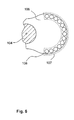
- FIG. 6 shows the example of a deformation zone 107. This is provided near the surface of the arranged on the shaft 104 piston 106. It comprises at least one or a plurality of bores 108. Upon contact of the pistons, the bores are compressed and the material located between the bores is deformed. This kinetic energy is reduced. The number and size of the holes is such that the deformation of the surface due to centrifugal forces is so small that the gaps between the pistons are not distorted with each other and between the piston and the housing. They are also dimensioned so that upon contact of the piston plastic deformation of the deformation zone is achieved.
- material can be used in the deformation zone with which a plastic deformation is achieved according to the aspects mentioned in relation to the bores.
- This deformation absorbs part of the energy released by contact, so that the energy emitted to the shaft and its Storage transmitted moments and forces are reduced.
- the bores can be closed at the end in a further development.
- the deformation zone is particularly effective in vacuum pumps whose pistons do not follow the gearing law, for example the Roots vacuum pumps.
Landscapes
- Engineering & Computer Science (AREA)
- Mechanical Engineering (AREA)
- General Engineering & Computer Science (AREA)
- Compressors, Vaccum Pumps And Other Relevant Systems (AREA)
Abstract
Description
- Die Erfindung betrifft eine Vakuumpumpe nach dem Oberbegriff des ersten Anspruchs.
- Zweiwellige Vakuumpumpen sind aus vielen industriellen Anwendungen nicht mehr wegzudenken. Beispielhaft seien für diese Anwendungen Metallurgie, Vakuumtrocknung und Chemietechnik genannt.
- Der Grundaufbau dieser Vakuumpumpen sieht vor, zwei Wellen gegenläufig mit gleicher Drehzahl zu betreiben. Dies wird beispielsweise durch ein mechanisches Synchrongetriebe gewährleistet. Auf diesen Wellen sind Kolben vorgesehen, die zusammenwirken, Gasvolumina einschließen und vom Pumpeneinlass zum Pumpenauslass transferieren.
- Obwohl in der Praxis selten, ist es denkbar, dass es zu einer gegenseitigen Berührung der Kolben kommt. Hierdurch wird schlagartig die in den Kolben gespeicherte Rotationsenergie freigesetzt. In der Folge kann es zu einer Gefährdung der Umgebung der Vakuumpumpe durch umherfliegende Bruchstücke, Teile oder austretende Gase kommen. Es besteht sogar noch die Forderung, höhere Saugvermögen mit zunehmend kompakteren Vakuumpumpen zu erreichen. In der Folge wird versucht, die Drehzahl der Wellen zu erhöhen. Höhere Drehzahlen bedeuten jedoch auch eine nichtlineare Steigerung der in den drehenden Teilen gespeicherten Rotationsenergie. Dementsprechend nimmt die Gefährdung der Umgebung der Vakuumpumpe zu.
- Es ist daher Aufgabe der Erfindung, eine zweiwellige Vakuumpumpe vorzustellen, in der die Gefährdung durch eine Kolbenberührung verringert ist.
- Diese Aufgabe wird gelöst durch eine Vakuumpumpe mit den Merkmalen des ersten Patentanspruchs. Die abhängigen Ansprüche 2 bis 6 geben vorteilhafte Weiterbildungen der Erfindung an.
- Bei zweiwelligen Vakuumpumpen wie Klauen-, Schrauben- oder Wälzkolbenpumpen wird bei einer Berühung der Kolben ein Moment in die Lager eingeleitet. Der Kerngedanke der Erfindung ist, zwischen dem Punkt der Momenteinleitung, nämlich den sich berührenden Kolbenoberflächen, und den Wellenlagern eine Freigabestruktur vorzusehen. Diese unterbricht den Momentenfluss, indem durch sie eine Verdrehung von Kolben und Welle relativ zueinander zugelassen ist. Daher werden die Momente in deutlich verringertem Maße auf die Lager und in der Folge in verringertem Maße auf das Gehäuse übertragen. Hierdurch wird die Sicherheit bei einer Berührung der Kolben deutlich erhöht.
- Vorteilhaft, da konstruktiv einfach, ist es, die Freigabestruktur in die Verbindung von Welle und Kolben zu legen. Bei zweiteilig gefertigten Rotoren, bei denen Welle und Kolben getrennt voneinander hergestellt werden, müssen immer Maßnahmen getroffen werden, die beiden Bauteile miteinander zu verbinden. Demzufolge ist der Aufwand sehr gering, indem diese Verbindung als Freigabestruktur gestaltet wird. In den Ansprüchen 3 und 4 sind konstruktiv einfache und kostengünstige Ausführungen angegeben.
- In manchen Pumpen werden Welle und Kolben aus einem Stück hergestellt oder stoffschlüssig miteinander verbunden. Auch hier ist es vorteilhaft, da konstruktiv einfach und kostengünstig, den Übergang von Welle auf Kolben derart zu gestalten, dass bei einer Berührung der Kolben dieser Übergang nachgibt.
- Eine Verformungszone in wenigstens einem der Kolben als Weiterbildung der Erfindung bewirkt eine weitere Erhöhung der Sicherheit. In dieser Verformungszone wird zusätzlich Bewegungsenergie durch plastische Verformung abgebaut, so dass die auf die Lager übertragenen Momente zusätzlich verringert werden.
- Anhand eines Ausführungsbeispiels und seiner Weiterbildungen soll die Erfindung erläutert und die Darstellung ihrer Vorteile vertieft werden. Es zeigen:
- Fig. 1:
- Schnitt durch eine zweiwellige Vakuumpumpe.
- Fig. 2:
- Schnitt durch die Verbindung von Welle und Kolben in einer ersten erfindungsgemäßen Gestaltungsform.
- Fig. 3:
- Schnitt durch die Verbindung von Welle und Kolben in einer zweiten erfindungsgemäßen Gestaltungsform.
- Fig. 4:
- Schnitt durch die Verbindung von Welle und Kolben in einer dritten erfindungsgemäßen Gestaltungsform.
- Fig. 5:
- Schnitt durch die Verbindung von Welle und Kolben in einer vierten erfindungsgemäßen Gestaltungsform.
- Fig. 6:
- Querschnitt durch einen Kolben mit Verformungszone.
- Einen Schnitt entlang der Achsen einer Wälzkolbenvakuumpumpe zeigt
Figur 1 . Im Gehäuse 1 der Vakuumpumpe befindet sich der Pumpraum 2. Dieser wird von einer ersten Welle 10 und einer zweiten Welle 14 durchsetzt. In Richtung der Wellenachsen ist er durch ein erstes Lagerschild 4 und ein zweites Lagerschild 5 begrenzt. In dem Bereich der Wellen, der den Pumpraum durchsetzt, sind ein erster Kolben 12 mit der ersten Welle und zweiter Kolben 14 mit der zweiten Welle verbunden. - Beide Wellen stützen sich durch Lageranordnungen drehbar in den Lagerschilden ab. Im ersten Lagerschild befinden sich das Loslager 22 der ersten Welle und das Loslager 26 der zweiten Welle. Im zweiten Lagerschild befinden sich das Festlager 24 der ersten Welle und das Festlager 26 der zweiten Welle.
- Auf der dem Pumpraum abgewandten Seite des ersten Lagerschildes ist ein Getrieberaum 3 vorgesehen, in den die Enden von erster und zweiter Welle hineinragen. Auf den Wellenenden sitzen ein erstes und ein zweites Synchronrad 18 und 20, welche die Drehung der ersten Wellen auf die zweite Welle übertragen, so dass die beiden Wellen gegenläufig mit gleicher Frequenz drehend in Rotation versetzt sind. Eine erste Schleuderscheibe 30 taucht in einen Schmiermittelvorrat und verteilt das Schmiermittel im Getrieberaum.
- Auf der dem Pumpraum abgewandten Seite des zweiten Lagerschildes befindet sich ein Zwischenraum 8. Dieser wird von der ersten Welle durchsetzt, während die zweite Welle in ihm endet. Auf ihrem Ende ist eine zweite Schleuderscheibe 32 angeordnet, die ebenfalls in einem Schmiermittelvorrat eintaucht und eine Verteilung des Schmiermittels im Zwischenraum bewirkt.
- Das den Zwischenraum durchsetzende Ende der ersten Welle endet im Motorgehäuse 6. Dort sind auf dem Wellenende Innenmagnete 44 befestigt. Das Wellenende mit den Innenmagneten ist von einem Spalttopf 40 umgeben, der mittels eines Spalttopfflansches am Gehäuse luftdicht angebracht ist. Ein Magneträger 48 trägt Außenmagnete 46, die mit den Innenmagneten kraft- und drehungsübertragend zusammenwirken. Der Magnetträger ist auf einer Motorwelle 50 angeordnet, welche in einem Motorlager 52 gelagert ist. Die ebenfalls auf der Motorwelle angeordneten Motormagnete 54 wirken mit Spulen 56 zusammen um elektrische Energie in mechanische Drehung umzusetzen.
- Vorteilhaft ist es, die Freigabestruktur in die Verbindung zwischen Welle und Kolben zu legen. Die
Figuren 2 bis 5 stellen Beispiele für solche Verbindungen vor, wobei jeweils der Wellenstumpf, auf dem Loslager, Festlager, Synchronräder und Schleuderscheiben sitzen, und der Stirnbereich des Kolbens im Schnitt gezeigt sind. Die Maßnahmen sind auf beide Kolben 12 und 16 und den jeweiligen Verbindungen zu den Wellen 10 und 14 anwendbar. - In
Figur 2 ist in der Schnittdarstellung die Welle 14 in einer zentralen Bohrung des Kolben 16 angeordnet. Die Welle weist eine Nut 61 auf, der eine Nut 62 am Kolben gegenübersteht. In die beiden Nuten 61 und 62 ist ein Bolzen 60 eingesetzt und bildet einen Formschluss. Dieser Bolzen ist so gestaltet, dass er den Kräften widerstehen kann, die bei Beschleunigen aus dem Stand und Abbremsen in den Stand auftreten. Bei abnormalen Kräften, die für eine Berührung der Kolben untereinander oder mit dem Gehäuse charakteristisch sind, verformt sich der Bolzen und lässt in der Folge eine Verdrehung von Kolben und Welle gegeneinander zu. Bei hohen Kräften schert der Bolzen komplett ab. - In
Figur 3 weist der Kolben 76 einen hülsenartigen Fortsatz 70 auf. Dessen Innenseite wird mittels eines in seiner Umfangsrichtung geschlossenen Klemmringes 71 auf die Welle 74 gepresst. Der hierdurch entstehende Kraftschluss wird aufgehoben, wenn hohe Kräfte in den Kolben eingeleitet werden. Die Grenze der Klemmkräfte ist so bemessen, dass die Position von Kolben und Welle bei Beschleunigen aus dem Stand und Abbremsen in den Stand unverändert bleibt. Erst in den Kolben eingeleitete Kräfte, wie sie im bestimmungsgemäßen Gebrauch der Pumpe nicht auftreten, lösen die Verbindung. - In
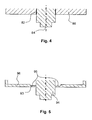
Figur 4 ist die Welle 84 in den Kolben 86 eingeklebt. Die Klebeverbindung ist dabei nach oben bereits genannten Gesichtspunkten gestaltet, gibt also nur bei ungewöhnlichen hohen Kräften nach. - Ein anderer Weg ist in
Figur 5 gezeigt. Welle 94 und Kolben 96 sind einstückig gestaltet. Der Kolben weist in seinem Inneren einen großen Hohlraum auf. Die Welle ist von einem Kranz von Bohrungen 95 umgeben, welche in einem dünnen Wandstück der Kolbenwand geformt ist. Dünnes Wandstück und Bohrungen bilden eine geschwächte Stelle und damit die Freigabestruktur. Die Stärke des Materials, die Dicke des dünnen Wandstücks und Größe und Anzahl der Bohrungen sind nach den oben beschriebenen Gesichtspunkten gewählt. Außergewöhnliche Kräfte werden durch Verformung aufgefangen, so dass sie nicht in die Fest- und Loslager eingeleitet werden. Alternativ zu den Bohrungen kann das Material des dünnen Wandstückes so gewählt werden, dass den genannten Bedingungen für die Freigabestruktur genügt wird. Materialwahl und Bohrungen können für sich alleine oder in Kombination miteinander eingesetzt werden. - Zusätzlich zu den bisher beschriebenen Maßnahmen ist eine sinnvolle Weiterbildung der Erfindung, wenigstens eine Verformungszone in dem Kolben vorzusehen.
Figur 6 zeigt das Beispiel einer Verformungszone 107. Diese ist nahe der Oberfläche des auf der Welle 104 angeordneten Kolbens 106 vorgesehen. Sie umfasst wenigstens eine oder eine Mehrzahl von Bohrungen 108. Bei einer Berührung der Kolben werden die Bohrungen zusammengedrückt und das zwischen den Bohrungen befindliche Material verformt. Hierbei wird Bewegungsenergie abgebaut. Die Zahl und Größe der Bohrungen ist derart bemessen, dass die Verformung der Oberfläche aufgrund von Fliehkräften so klein ist, dass die Spalte zwischen den Kolben untereinander und zwischen Kolben und Gehäuse nicht aufgezerrt werden. Sie sind außerdem so bemessen, dass bei Berührung der Kolben eine plastische Verformung der Verformungszone erreicht wird. Alternativ oder zusätzlich zu den Bohrungen kann in der Verformungszone Material verwendet werden, mit dem eine plastische Verformung nach den in Bezug auf die Bohrungen genannten Gesichtspunkten erreicht wird. Diese Verformung nimmt einen Teil der bei einer Berührung freiwerdenden Energie auf, so dass die auf die Welle und deren Lagerung übertragenen Momente und Kräfte verringert werden. Um einen Einfluss der Bohrungen auf die vakuumtechnischen Daten der Wälzkolbenvakuumpumpe zu verringern, können in einer Weiterbildung die Bohrungen stirnseitig verschlossen werden. Die Verformungszone ist besonders wirkungsvoll bei Vakuumpumpen, deren Kolben nicht dem Verzahnungsgesetz folgen, beispielsweise den Wälzkolbenvakuumpumpen.
Claims (6)
- Vakuumpumpe mit einer ersten Welle (10), einem damit verbundenen ersten Kolben (12), einer zweiten Welle (14), einem damit verbundenen zweiten Kolben (16), einem Antrieb (54, 56), welcher wenigstens eine Welle in Drehung versetzt, und wenigstens einem Lager (22, 24, 26, 28) zur drehbaren Unterstützung einer Welle, dadurch gekennzeichnet, dass zwischen Kolben und Lager eine Freigabestruktur vorgesehen ist.
- Vakuumpumpe nach Anspruch 1, dadurch gekennzeichnet, dass die Freigabestruktur eine derart gestaltete Verbindung zwischen Welle (10, 14; 74; 84) und Kolben (12, 16; 76; 86) umfasst, dass die Verbindung bei einer Berührung der Kolben gelöst wird.
- Vakuumpumpe nach Anspruch 1 oder 2, dadurch gekennzeichnet, dass die Freigabestruktur einen zwischen Welle (10, 14) und Kolben (12, 16) angeordneten Bolzen (60) umfasst.
- Vakuumpumpe nach Anspruch 1 oder 2, dadurch gekennzeichnet, dass die Freigabestruktur einen Klemmring (71) und einen hülsenartigen Fortsatz (70) umfasst.
- Vakuumpumpe nach Anspruch 1 oder 2, dadurch gekennzeichnet, dass die Freigabestruktur eine stoffschlüssige Verbindung (82; 93) von Kolben (12, 16; 96) und Welle (10, 14; 94) umfasst, die derart gestaltet ist, dass die Verbindung bei einer Berührung der Kolben gelöst wird.
- Vakuumpumpe nach einem der vorhergehenden Ansprüche, dadurch gekennzeichnet, dass wenigstens ein Kolben (12, 16; 76; 86; 96; 106) eine Verformungszone (107) aufweist.
Applications Claiming Priority (1)
| Application Number | Priority Date | Filing Date | Title |
|---|---|---|---|
| DE102008060539A DE102008060539A1 (de) | 2008-12-04 | 2008-12-04 | Zweiwellige Vakuumpumpe |
Publications (3)
| Publication Number | Publication Date |
|---|---|
| EP2194276A2 true EP2194276A2 (de) | 2010-06-09 |
| EP2194276A3 EP2194276A3 (de) | 2014-08-27 |
| EP2194276B1 EP2194276B1 (de) | 2020-09-09 |
Family
ID=41796156
Family Applications (1)
| Application Number | Title | Priority Date | Filing Date |
|---|---|---|---|
| EP09014529.3A Active EP2194276B1 (de) | 2008-12-04 | 2009-11-20 | Zweiwellige Vakuumpumpe |
Country Status (2)
| Country | Link |
|---|---|
| EP (1) | EP2194276B1 (de) |
| DE (1) | DE102008060539A1 (de) |
Family Cites Families (11)
| Publication number | Priority date | Publication date | Assignee | Title |
|---|---|---|---|---|
| DE810419C (de) * | 1949-01-01 | 1951-08-09 | Otto Becker | Drehkolbengeblaese |
| FR96392E (fr) * | 1968-11-07 | 1972-06-16 | Eisenwerke Kaiserslautern G M | Pompe a pistons rotatifs pour produits visqueux. |
| JPS59160084A (ja) * | 1983-03-02 | 1984-09-10 | Nippon Denso Co Ltd | 回転式流体圧送装置 |
| JPS6075793A (ja) * | 1983-09-30 | 1985-04-30 | Aisin Seiki Co Ltd | ル−ツ型ブロア |
| US4662826A (en) * | 1984-04-20 | 1987-05-05 | Tokico Ltd. | Vacuum pump system including serially connected rotary and reciprocating vacuum pumps |
| JPH0623753Y2 (ja) * | 1985-07-26 | 1994-06-22 | トヨタ自動車株式会社 | ル−ツ式ポンプ |
| WO1997012158A1 (de) * | 1995-09-28 | 1997-04-03 | Muellenberg Ralph | Anordnung zur übertragung eines drehmoments |
| DE19807923A1 (de) * | 1997-03-03 | 1998-11-12 | Luk Fahrzeug Hydraulik | Kompressor für eine Klimaanlage eines Kraftfahrzeugs |
| JPH10259830A (ja) * | 1997-03-21 | 1998-09-29 | Toyota Autom Loom Works Ltd | 動力伝達構造 |
| JP2005226451A (ja) * | 2004-02-10 | 2005-08-25 | Zexel Valeo Climate Control Corp | 圧縮機のトルク伝達装置 |
| DE102005057618A1 (de) * | 2005-12-02 | 2007-06-06 | Pfeiffer Vacuum Gmbh | Verfahren zum Betrieb einer Vakuumpumpe |
-
2008
- 2008-12-04 DE DE102008060539A patent/DE102008060539A1/de not_active Withdrawn
-
2009
- 2009-11-20 EP EP09014529.3A patent/EP2194276B1/de active Active
Also Published As
| Publication number | Publication date |
|---|---|
| EP2194276A3 (de) | 2014-08-27 |
| DE102008060539A1 (de) | 2010-06-10 |
| EP2194276B1 (de) | 2020-09-09 |
Similar Documents
| Publication | Publication Date | Title |
|---|---|---|
| DE102008064815B3 (de) | Spindelmotor mit fluiddynamischem Lagersystem und feststehender WeIle | |
| DE3883563T2 (de) | Mehrfach magnetisch angetriebene Pumpe. | |
| DE3126243C2 (de) | Nebenantrieb einer Brennkraftmaschine | |
| EP3793630A1 (de) | Rotorlagerungssystem | |
| EP2971815B1 (de) | Gleitlagerbefestigung in einem kreiselpumpenaggregat | |
| DE3320699C2 (de) | Vorrichtung zum Verändern des Leitschaufelwinkels bei axialen Strömungsmaschinen | |
| EP0437470A1 (de) | Sperrbares differentialgetriebe. | |
| EP1508712A2 (de) | Kupplung mit Torsionsschwingungsdämpfer | |
| DE102011078110A1 (de) | Antriebselement eines Getriebes | |
| DE3826256A1 (de) | Antriebsdrehmoment-uebertragungsvorrichtung | |
| DE2835340A1 (de) | Oelgekuehlte antriebseinheit | |
| EP2194275B1 (de) | Wälzkolbenvakuumpumpe | |
| DE68905003T2 (de) | Bremsmechanismus fuer fahrzeuge. | |
| DE102007019667A1 (de) | Lagervorrichtung | |
| EP1746290A1 (de) | Radialverdichter | |
| EP0666422A1 (de) | Lagerung und Antrieb der Rotoren eines Schraubenrotorverdichters | |
| EP0337950A2 (de) | Innenachsige Rotationskolbenmaschine | |
| EP2194276B1 (de) | Zweiwellige Vakuumpumpe | |
| DE102009038767B4 (de) | Reibschaltkupplung zur Betätigung mit einem strömungsfähigen Druckmittel | |
| DE102024210942A1 (de) | Hydrostatische Rotationsmaschine mit optimierter Bremse | |
| DE102016224898A1 (de) | Pumpeneinrichtung für ein Automatikgetriebe | |
| DE102019214279A1 (de) | Seitenkanalverdichter für ein Brennstoffzellensystem zur Förderung und/oder Verdichtung eines gasförmigen Mediums | |
| EP3045728B1 (de) | Spiralvakuumpumpe | |
| DE102018219995A1 (de) | Seitenkanalverdichter für ein Brennstoffzellensystem zur Förderung und/oder Verdichtung von einem gasförmigen Medium | |
| EP3088745B1 (de) | Rotoranordnung für eine vakuumpumpe und vakuumpumpe |
Legal Events
| Date | Code | Title | Description |
|---|---|---|---|
| PUAI | Public reference made under article 153(3) epc to a published international application that has entered the european phase |
Free format text: ORIGINAL CODE: 0009012 |
|
| AK | Designated contracting states |
Kind code of ref document: A2 Designated state(s): AT BE BG CH CY CZ DE DK EE ES FI FR GB GR HR HU IE IS IT LI LT LU LV MC MK MT NL NO PL PT RO SE SI SK SM TR |
|
| AX | Request for extension of the european patent |
Extension state: AL BA RS |
|
| PUAL | Search report despatched |
Free format text: ORIGINAL CODE: 0009013 |
|
| AK | Designated contracting states |
Kind code of ref document: A3 Designated state(s): AT BE BG CH CY CZ DE DK EE ES FI FR GB GR HR HU IE IS IT LI LT LU LV MC MK MT NL NO PL PT RO SE SI SK SM TR |
|
| AX | Request for extension of the european patent |
Extension state: AL BA RS |
|
| RIC1 | Information provided on ipc code assigned before grant |
Ipc: F04C 28/28 20060101ALI20140718BHEP Ipc: F04C 18/12 20060101AFI20140718BHEP |
|
| 17P | Request for examination filed |
Effective date: 20150205 |
|
| RBV | Designated contracting states (corrected) |
Designated state(s): AT BE BG CH CY CZ DE DK EE ES FI FR GB GR HR HU IE IS IT LI LT LU LV MC MK MT NL NO PL PT RO SE SI SK SM TR |
|
| 17Q | First examination report despatched |
Effective date: 20160322 |
|
| STAA | Information on the status of an ep patent application or granted ep patent |
Free format text: STATUS: EXAMINATION IS IN PROGRESS |
|
| GRAP | Despatch of communication of intention to grant a patent |
Free format text: ORIGINAL CODE: EPIDOSNIGR1 |
|
| STAA | Information on the status of an ep patent application or granted ep patent |
Free format text: STATUS: GRANT OF PATENT IS INTENDED |
|
| INTG | Intention to grant announced |
Effective date: 20200511 |
|
| GRAS | Grant fee paid |
Free format text: ORIGINAL CODE: EPIDOSNIGR3 |
|
| GRAA | (expected) grant |
Free format text: ORIGINAL CODE: 0009210 |
|
| STAA | Information on the status of an ep patent application or granted ep patent |
Free format text: STATUS: THE PATENT HAS BEEN GRANTED |
|
| AK | Designated contracting states |
Kind code of ref document: B1 Designated state(s): AT BE BG CH CY CZ DE DK EE ES FI FR GB GR HR HU IE IS IT LI LT LU LV MC MK MT NL NO PL PT RO SE SI SK SM TR |
|
| REG | Reference to a national code |
Ref country code: GB Ref legal event code: FG4D Free format text: NOT ENGLISH |
|
| REG | Reference to a national code |
Ref country code: AT Ref legal event code: REF Ref document number: 1311908 Country of ref document: AT Kind code of ref document: T Effective date: 20200915 Ref country code: CH Ref legal event code: EP |
|
| REG | Reference to a national code |
Ref country code: DE Ref legal event code: R096 Ref document number: 502009016267 Country of ref document: DE |
|
| REG | Reference to a national code |
Ref country code: IE Ref legal event code: FG4D Free format text: LANGUAGE OF EP DOCUMENT: GERMAN |
|
| REG | Reference to a national code |
Ref country code: LT Ref legal event code: MG4D |
|
| PG25 | Lapsed in a contracting state [announced via postgrant information from national office to epo] |
Ref country code: GR Free format text: LAPSE BECAUSE OF FAILURE TO SUBMIT A TRANSLATION OF THE DESCRIPTION OR TO PAY THE FEE WITHIN THE PRESCRIBED TIME-LIMIT Effective date: 20201210 Ref country code: LT Free format text: LAPSE BECAUSE OF FAILURE TO SUBMIT A TRANSLATION OF THE DESCRIPTION OR TO PAY THE FEE WITHIN THE PRESCRIBED TIME-LIMIT Effective date: 20200909 Ref country code: BG Free format text: LAPSE BECAUSE OF FAILURE TO SUBMIT A TRANSLATION OF THE DESCRIPTION OR TO PAY THE FEE WITHIN THE PRESCRIBED TIME-LIMIT Effective date: 20201209 Ref country code: FI Free format text: LAPSE BECAUSE OF FAILURE TO SUBMIT A TRANSLATION OF THE DESCRIPTION OR TO PAY THE FEE WITHIN THE PRESCRIBED TIME-LIMIT Effective date: 20200909 Ref country code: NO Free format text: LAPSE BECAUSE OF FAILURE TO SUBMIT A TRANSLATION OF THE DESCRIPTION OR TO PAY THE FEE WITHIN THE PRESCRIBED TIME-LIMIT Effective date: 20201209 Ref country code: HR Free format text: LAPSE BECAUSE OF FAILURE TO SUBMIT A TRANSLATION OF THE DESCRIPTION OR TO PAY THE FEE WITHIN THE PRESCRIBED TIME-LIMIT Effective date: 20200909 Ref country code: SE Free format text: LAPSE BECAUSE OF FAILURE TO SUBMIT A TRANSLATION OF THE DESCRIPTION OR TO PAY THE FEE WITHIN THE PRESCRIBED TIME-LIMIT Effective date: 20200909 |
|
| REG | Reference to a national code |
Ref country code: NL Ref legal event code: MP Effective date: 20200909 |
|
| PG25 | Lapsed in a contracting state [announced via postgrant information from national office to epo] |
Ref country code: PL Free format text: LAPSE BECAUSE OF FAILURE TO SUBMIT A TRANSLATION OF THE DESCRIPTION OR TO PAY THE FEE WITHIN THE PRESCRIBED TIME-LIMIT Effective date: 20200909 Ref country code: LV Free format text: LAPSE BECAUSE OF FAILURE TO SUBMIT A TRANSLATION OF THE DESCRIPTION OR TO PAY THE FEE WITHIN THE PRESCRIBED TIME-LIMIT Effective date: 20200909 |
|
| PG25 | Lapsed in a contracting state [announced via postgrant information from national office to epo] |
Ref country code: EE Free format text: LAPSE BECAUSE OF FAILURE TO SUBMIT A TRANSLATION OF THE DESCRIPTION OR TO PAY THE FEE WITHIN THE PRESCRIBED TIME-LIMIT Effective date: 20200909 Ref country code: SM Free format text: LAPSE BECAUSE OF FAILURE TO SUBMIT A TRANSLATION OF THE DESCRIPTION OR TO PAY THE FEE WITHIN THE PRESCRIBED TIME-LIMIT Effective date: 20200909 Ref country code: RO Free format text: LAPSE BECAUSE OF FAILURE TO SUBMIT A TRANSLATION OF THE DESCRIPTION OR TO PAY THE FEE WITHIN THE PRESCRIBED TIME-LIMIT Effective date: 20200909 Ref country code: PT Free format text: LAPSE BECAUSE OF FAILURE TO SUBMIT A TRANSLATION OF THE DESCRIPTION OR TO PAY THE FEE WITHIN THE PRESCRIBED TIME-LIMIT Effective date: 20210111 Ref country code: NL Free format text: LAPSE BECAUSE OF FAILURE TO SUBMIT A TRANSLATION OF THE DESCRIPTION OR TO PAY THE FEE WITHIN THE PRESCRIBED TIME-LIMIT Effective date: 20200909 |
|
| PG25 | Lapsed in a contracting state [announced via postgrant information from national office to epo] |
Ref country code: IS Free format text: LAPSE BECAUSE OF FAILURE TO SUBMIT A TRANSLATION OF THE DESCRIPTION OR TO PAY THE FEE WITHIN THE PRESCRIBED TIME-LIMIT Effective date: 20210109 Ref country code: ES Free format text: LAPSE BECAUSE OF FAILURE TO SUBMIT A TRANSLATION OF THE DESCRIPTION OR TO PAY THE FEE WITHIN THE PRESCRIBED TIME-LIMIT Effective date: 20200909 |
|
| REG | Reference to a national code |
Ref country code: DE Ref legal event code: R097 Ref document number: 502009016267 Country of ref document: DE |
|
| PG25 | Lapsed in a contracting state [announced via postgrant information from national office to epo] |
Ref country code: SK Free format text: LAPSE BECAUSE OF FAILURE TO SUBMIT A TRANSLATION OF THE DESCRIPTION OR TO PAY THE FEE WITHIN THE PRESCRIBED TIME-LIMIT Effective date: 20200909 Ref country code: MC Free format text: LAPSE BECAUSE OF FAILURE TO SUBMIT A TRANSLATION OF THE DESCRIPTION OR TO PAY THE FEE WITHIN THE PRESCRIBED TIME-LIMIT Effective date: 20200909 |
|
| REG | Reference to a national code |
Ref country code: CH Ref legal event code: PL |
|
| PLBE | No opposition filed within time limit |
Free format text: ORIGINAL CODE: 0009261 |
|
| STAA | Information on the status of an ep patent application or granted ep patent |
Free format text: STATUS: NO OPPOSITION FILED WITHIN TIME LIMIT |
|
| PG25 | Lapsed in a contracting state [announced via postgrant information from national office to epo] |
Ref country code: LU Free format text: LAPSE BECAUSE OF NON-PAYMENT OF DUE FEES Effective date: 20201120 |
|
| REG | Reference to a national code |
Ref country code: BE Ref legal event code: MM Effective date: 20201130 |
|
| 26N | No opposition filed |
Effective date: 20210610 |
|
| PG25 | Lapsed in a contracting state [announced via postgrant information from national office to epo] |
Ref country code: CH Free format text: LAPSE BECAUSE OF NON-PAYMENT OF DUE FEES Effective date: 20201130 Ref country code: DK Free format text: LAPSE BECAUSE OF FAILURE TO SUBMIT A TRANSLATION OF THE DESCRIPTION OR TO PAY THE FEE WITHIN THE PRESCRIBED TIME-LIMIT Effective date: 20200909 Ref country code: SI Free format text: LAPSE BECAUSE OF FAILURE TO SUBMIT A TRANSLATION OF THE DESCRIPTION OR TO PAY THE FEE WITHIN THE PRESCRIBED TIME-LIMIT Effective date: 20200909 Ref country code: LI Free format text: LAPSE BECAUSE OF NON-PAYMENT OF DUE FEES Effective date: 20201130 |
|
| PG25 | Lapsed in a contracting state [announced via postgrant information from national office to epo] |
Ref country code: FR Free format text: LAPSE BECAUSE OF NON-PAYMENT OF DUE FEES Effective date: 20201130 Ref country code: IE Free format text: LAPSE BECAUSE OF NON-PAYMENT OF DUE FEES Effective date: 20201120 |
|
| REG | Reference to a national code |
Ref country code: AT Ref legal event code: MM01 Ref document number: 1311908 Country of ref document: AT Kind code of ref document: T Effective date: 20201120 |
|
| PG25 | Lapsed in a contracting state [announced via postgrant information from national office to epo] |
Ref country code: AT Free format text: LAPSE BECAUSE OF NON-PAYMENT OF DUE FEES Effective date: 20201120 |
|
| PG25 | Lapsed in a contracting state [announced via postgrant information from national office to epo] |
Ref country code: TR Free format text: LAPSE BECAUSE OF FAILURE TO SUBMIT A TRANSLATION OF THE DESCRIPTION OR TO PAY THE FEE WITHIN THE PRESCRIBED TIME-LIMIT Effective date: 20200909 Ref country code: MT Free format text: LAPSE BECAUSE OF FAILURE TO SUBMIT A TRANSLATION OF THE DESCRIPTION OR TO PAY THE FEE WITHIN THE PRESCRIBED TIME-LIMIT Effective date: 20200909 Ref country code: CY Free format text: LAPSE BECAUSE OF FAILURE TO SUBMIT A TRANSLATION OF THE DESCRIPTION OR TO PAY THE FEE WITHIN THE PRESCRIBED TIME-LIMIT Effective date: 20200909 |
|
| PG25 | Lapsed in a contracting state [announced via postgrant information from national office to epo] |
Ref country code: MK Free format text: LAPSE BECAUSE OF FAILURE TO SUBMIT A TRANSLATION OF THE DESCRIPTION OR TO PAY THE FEE WITHIN THE PRESCRIBED TIME-LIMIT Effective date: 20200909 |
|
| PG25 | Lapsed in a contracting state [announced via postgrant information from national office to epo] |
Ref country code: BE Free format text: LAPSE BECAUSE OF NON-PAYMENT OF DUE FEES Effective date: 20201130 |
|
| PGFP | Annual fee paid to national office [announced via postgrant information from national office to epo] |
Ref country code: IT Payment date: 20221124 Year of fee payment: 14 Ref country code: GB Payment date: 20221125 Year of fee payment: 14 Ref country code: CZ Payment date: 20221111 Year of fee payment: 14 |
|
| PGFP | Annual fee paid to national office [announced via postgrant information from national office to epo] |
Ref country code: DE Payment date: 20230127 Year of fee payment: 14 |
|
| REG | Reference to a national code |
Ref country code: DE Ref legal event code: R119 Ref document number: 502009016267 Country of ref document: DE |
|
| PG25 | Lapsed in a contracting state [announced via postgrant information from national office to epo] |
Ref country code: CZ Free format text: LAPSE BECAUSE OF NON-PAYMENT OF DUE FEES Effective date: 20231120 |
|
| GBPC | Gb: european patent ceased through non-payment of renewal fee |
Effective date: 20231120 |
|
| PG25 | Lapsed in a contracting state [announced via postgrant information from national office to epo] |
Ref country code: CZ Free format text: LAPSE BECAUSE OF NON-PAYMENT OF DUE FEES Effective date: 20231120 |
|
| PG25 | Lapsed in a contracting state [announced via postgrant information from national office to epo] |
Ref country code: DE Free format text: LAPSE BECAUSE OF NON-PAYMENT OF DUE FEES Effective date: 20240601 |
|
| PG25 | Lapsed in a contracting state [announced via postgrant information from national office to epo] |
Ref country code: GB Free format text: LAPSE BECAUSE OF NON-PAYMENT OF DUE FEES Effective date: 20231120 |
|
| PG25 | Lapsed in a contracting state [announced via postgrant information from national office to epo] |
Ref country code: GB Free format text: LAPSE BECAUSE OF NON-PAYMENT OF DUE FEES Effective date: 20231120 Ref country code: DE Free format text: LAPSE BECAUSE OF NON-PAYMENT OF DUE FEES Effective date: 20240601 |
|
| PG25 | Lapsed in a contracting state [announced via postgrant information from national office to epo] |
Ref country code: IT Free format text: LAPSE BECAUSE OF NON-PAYMENT OF DUE FEES Effective date: 20231120 |
|
| PG25 | Lapsed in a contracting state [announced via postgrant information from national office to epo] |
Ref country code: IT Free format text: LAPSE BECAUSE OF NON-PAYMENT OF DUE FEES Effective date: 20231120 |