EP2193388B1 - Distance measuring instrument and method - Google Patents
Distance measuring instrument and method Download PDFInfo
- Publication number
- EP2193388B1 EP2193388B1 EP07818567.5A EP07818567A EP2193388B1 EP 2193388 B1 EP2193388 B1 EP 2193388B1 EP 07818567 A EP07818567 A EP 07818567A EP 2193388 B1 EP2193388 B1 EP 2193388B1
- Authority
- EP
- European Patent Office
- Prior art keywords
- signal
- light
- input
- output
- variable gain
- Prior art date
- Legal status (The legal status is an assumption and is not a legal conclusion. Google has not performed a legal analysis and makes no representation as to the accuracy of the status listed.)
- Active
Links
- 238000000034 method Methods 0.000 title claims description 13
- 239000000835 fiber Substances 0.000 claims description 23
- 230000003111 delayed effect Effects 0.000 claims description 10
- 229910052761 rare earth metal Inorganic materials 0.000 claims description 8
- 230000002123 temporal effect Effects 0.000 claims description 5
- 230000001419 dependent effect Effects 0.000 claims description 4
- 229910052691 Erbium Inorganic materials 0.000 claims description 3
- UYAHIZSMUZPPFV-UHFFFAOYSA-N erbium Chemical compound [Er] UYAHIZSMUZPPFV-UHFFFAOYSA-N 0.000 claims description 3
- 229910052769 Ytterbium Inorganic materials 0.000 claims description 2
- 230000008569 process Effects 0.000 claims description 2
- NAWDYIZEMPQZHO-UHFFFAOYSA-N ytterbium Chemical compound [Yb] NAWDYIZEMPQZHO-UHFFFAOYSA-N 0.000 claims description 2
- 238000004458 analytical method Methods 0.000 description 13
- 230000003321 amplification Effects 0.000 description 9
- 238000005259 measurement Methods 0.000 description 9
- 238000003199 nucleic acid amplification method Methods 0.000 description 9
- 230000003287 optical effect Effects 0.000 description 7
- 238000012545 processing Methods 0.000 description 7
- 230000006870 function Effects 0.000 description 5
- 238000012544 monitoring process Methods 0.000 description 4
- 150000002910 rare earth metals Chemical class 0.000 description 4
- 230000008901 benefit Effects 0.000 description 3
- 238000001514 detection method Methods 0.000 description 3
- 230000008859 change Effects 0.000 description 2
- 230000001934 delay Effects 0.000 description 2
- 230000005484 gravity Effects 0.000 description 2
- 239000006096 absorbing agent Substances 0.000 description 1
- 230000003044 adaptive effect Effects 0.000 description 1
- 239000003990 capacitor Substances 0.000 description 1
- 238000004891 communication Methods 0.000 description 1
- 239000004020 conductor Substances 0.000 description 1
- 238000010586 diagram Methods 0.000 description 1
- 230000005670 electromagnetic radiation Effects 0.000 description 1
- 238000012986 modification Methods 0.000 description 1
- 230000004048 modification Effects 0.000 description 1
- 230000009022 nonlinear effect Effects 0.000 description 1
- 230000005855 radiation Effects 0.000 description 1
- 238000007493 shaping process Methods 0.000 description 1
- 230000002269 spontaneous effect Effects 0.000 description 1
- 230000006641 stabilisation Effects 0.000 description 1
- 238000011105 stabilization Methods 0.000 description 1
- 238000010897 surface acoustic wave method Methods 0.000 description 1
- 239000013598 vector Substances 0.000 description 1
Images


Classifications
-
- G—PHYSICS
- G01—MEASURING; TESTING
- G01C—MEASURING DISTANCES, LEVELS OR BEARINGS; SURVEYING; NAVIGATION; GYROSCOPIC INSTRUMENTS; PHOTOGRAMMETRY OR VIDEOGRAMMETRY
- G01C3/00—Measuring distances in line of sight; Optical rangefinders
- G01C3/02—Details
- G01C3/06—Use of electric means to obtain final indication
- G01C3/08—Use of electric radiation detectors
-
- H—ELECTRICITY
- H03—ELECTRONIC CIRCUITRY
- H03G—CONTROL OF AMPLIFICATION
- H03G3/00—Gain control in amplifiers or frequency changers without distortion of the input signal
- H03G3/20—Automatic control
- H03G3/30—Automatic control in amplifiers having semiconductor devices
- H03G3/3084—Automatic control in amplifiers having semiconductor devices in receivers or transmitters for electromagnetic waves other than radiowaves, e.g. lightwaves
-
- G—PHYSICS
- G01—MEASURING; TESTING
- G01S—RADIO DIRECTION-FINDING; RADIO NAVIGATION; DETERMINING DISTANCE OR VELOCITY BY USE OF RADIO WAVES; LOCATING OR PRESENCE-DETECTING BY USE OF THE REFLECTION OR RERADIATION OF RADIO WAVES; ANALOGOUS ARRANGEMENTS USING OTHER WAVES
- G01S17/00—Systems using the reflection or reradiation of electromagnetic waves other than radio waves, e.g. lidar systems
- G01S17/02—Systems using the reflection of electromagnetic waves other than radio waves
- G01S17/06—Systems determining position data of a target
- G01S17/08—Systems determining position data of a target for measuring distance only
- G01S17/10—Systems determining position data of a target for measuring distance only using transmission of interrupted, pulse-modulated waves
-
- G—PHYSICS
- G01—MEASURING; TESTING
- G01S—RADIO DIRECTION-FINDING; RADIO NAVIGATION; DETERMINING DISTANCE OR VELOCITY BY USE OF RADIO WAVES; LOCATING OR PRESENCE-DETECTING BY USE OF THE REFLECTION OR RERADIATION OF RADIO WAVES; ANALOGOUS ARRANGEMENTS USING OTHER WAVES
- G01S7/00—Details of systems according to groups G01S13/00, G01S15/00, G01S17/00
- G01S7/48—Details of systems according to groups G01S13/00, G01S15/00, G01S17/00 of systems according to group G01S17/00
- G01S7/481—Constructional features, e.g. arrangements of optical elements
- G01S7/4814—Constructional features, e.g. arrangements of optical elements of transmitters alone
-
- G—PHYSICS
- G01—MEASURING; TESTING
- G01S—RADIO DIRECTION-FINDING; RADIO NAVIGATION; DETERMINING DISTANCE OR VELOCITY BY USE OF RADIO WAVES; LOCATING OR PRESENCE-DETECTING BY USE OF THE REFLECTION OR RERADIATION OF RADIO WAVES; ANALOGOUS ARRANGEMENTS USING OTHER WAVES
- G01S7/00—Details of systems according to groups G01S13/00, G01S15/00, G01S17/00
- G01S7/48—Details of systems according to groups G01S13/00, G01S15/00, G01S17/00 of systems according to group G01S17/00
- G01S7/481—Constructional features, e.g. arrangements of optical elements
- G01S7/4818—Constructional features, e.g. arrangements of optical elements using optical fibres
-
- G—PHYSICS
- G01—MEASURING; TESTING
- G01S—RADIO DIRECTION-FINDING; RADIO NAVIGATION; DETERMINING DISTANCE OR VELOCITY BY USE OF RADIO WAVES; LOCATING OR PRESENCE-DETECTING BY USE OF THE REFLECTION OR RERADIATION OF RADIO WAVES; ANALOGOUS ARRANGEMENTS USING OTHER WAVES
- G01S7/00—Details of systems according to groups G01S13/00, G01S15/00, G01S17/00
- G01S7/48—Details of systems according to groups G01S13/00, G01S15/00, G01S17/00 of systems according to group G01S17/00
- G01S7/483—Details of pulse systems
- G01S7/486—Receivers
- G01S7/4868—Controlling received signal intensity or exposure of sensor
-
- G—PHYSICS
- G01—MEASURING; TESTING
- G01S—RADIO DIRECTION-FINDING; RADIO NAVIGATION; DETERMINING DISTANCE OR VELOCITY BY USE OF RADIO WAVES; LOCATING OR PRESENCE-DETECTING BY USE OF THE REFLECTION OR RERADIATION OF RADIO WAVES; ANALOGOUS ARRANGEMENTS USING OTHER WAVES
- G01S7/00—Details of systems according to groups G01S13/00, G01S15/00, G01S17/00
- G01S7/48—Details of systems according to groups G01S13/00, G01S15/00, G01S17/00 of systems according to group G01S17/00
- G01S7/497—Means for monitoring or calibrating
Definitions
- the present invention relates to a distance measuring instrument and a distance measuring method.
- the invention relates to a distance measuring instrument and method where modulated measuring light is emitted towards an object and wherein measuring light received back from the object is detected and analyzed. A value representing a distance from the object is determined based on such analysis.
- a conventional distance measuring instrument comprises a laser generating pulses of measuring light, and optics to direct the pulses of measuring light towards an object. Pulses of measuring light received back from the object are supplied to a light sensor to generate electrical signals corresponding to the light pulses, and the electrical pulse signals are amplified and analyzed. The analysis includes determination of occurrence times between subsequent pulses to determine the distance from the object based on the determined occurrence times.
- US 2005/0094238 A1 discloses a distance measuring instrument comprising a light source, a light detector, optics configured to direct measuring light emitted from the light source towards an object and to direct measuring light received back from the object to the detector, a first signal analyser, a second signal analyser, and a variable gain amplifier, wherein an output of the light sensor is connected to an input of the variable gain amplifier, and output of the variable gain amplifier is connected to a signal input of the first signal analyzer, an output of the first signal analyzer is connected to a gain setting input of the variable gain amplifier, an output of the variable gain amplifier is connected to an input of the second signal analyzer, and wherein the second signal analyzer is configured to determine occurrence times of a predetermined signal feature of signals supplied to its input relative to emission times of pulses of measuring light directed to the object.
- the distance measuring instrument comprises a variable gain amplifier for amplifying a detected signal, wherein a higher gain is applied when the detected signal has a low intensity and wherein a relatively lower gain -is applied when the detected signal has a relatively higher intensity.
- the distance measuring instrument comprises a first analyzer for analyzing the detected signal such that the gain of the variable gain amplifier can be set based on a result of this analysis.
- the distance measuring instrument comprises a signal delay module for delaying a first portion of a detected signal, wherein a first analysis of a second portion of the detected signal is performed while the first portion is delayed.
- a signal delay module for delaying a first portion of a detected signal, wherein a first analysis of a second portion of the detected signal is performed while the first portion is delayed.
- the gain value is determined such that the amplified signal outputted from the variable gain amplifier has a substantially constant intensity which is relatively independent of the intensity of the detected signal.
- the amplified signal can then be subject to further analysis, wherein this analysis is relatively independent of the intensity of the original detected signal. This can be of a particular advantage in practice since measuring light received back from the object and the corresponding detected signals may vary by many orders of magnitude, depending on the distance of the object from the measuring instrument and on an albedo of the object.
- a distance measuring instrument comprises at least one light source; at least one light detector; optics to direct measuring light emitted from the at least one light source towards an object and to direct measuring light received back from the object to the at least one detector; a signal delay module; a first signal analyzer; and a variable gain amplifier; wherein: an output of the at least one light sensor is connected to an input of the signal delay module; the output of the at least one light sensor is connected to a signal input of the first signal analyzer; an output of the signal delay module is connected to a signal input of the variable gain amplifier; and an output of the first signal analyzer is connected to a gain setting input of the variable gain amplifier.
- connection is not limited to mean directly connected but shall also encompass functional connections with intermediate components.
- an output of a first component is connected to an input of a second component this comprises a direct connection wherein an electrical conductor directly supplies an outputted signal from the first component substantially unchanged to the input of the second component, and this also comprise that the connection is via one or more additional components, such as an intermediate amplifier or filter which modifies the signal outputted from the first component before it is inputted to the second component.
- additional components such as an intermediate amplifier or filter which modifies the signal outputted from the first component before it is inputted to the second component.
- the connection is a functional connection in that, if the signal outputted from the first component undergoes gradual or prompt changes, a corresponding and maybe modified change will be applied to the input of the second component.
- the signal delay module delays an inputted signal by a predetermined signal delay time before it is outputted.
- the signal delay time can be greater than or equal to one of a processing time associated with the first signal analyzer, a settling time associated with the variable gain amplifier, and a sum of the processing time of the first signal analyzer and the settling time of the variable gain amplifier.
- the processing time associated with the first signal analyzer is defined in the context of the present invention as the time elapsed from the application of an ideal instantaneous step signal to the input of the first signal analyzer to a time at which the output of the first signal analyzer has entered and remained within a value range between 0.5 to 1.5 times the final value established at the output of the first signal analyzer.
- the settling time associated with the variable gain amplifier is defined in the context of the present invention as the time elapsed from supplying the settled output from the first signal analyzer to the variable gain amplifier and a time when the variable gain amplifier has adjusted its amplification to its final value with an accuracy within 0.5 to 1.5 times the final value of the adjusted amplification.
- the signal delay time is greater than one of 0.5 ns, 1.0 ns, 3 ns, 5 ns and 7 ns.
- the first signal analyzer is configured to provide an output signal at its output which is indicative of an intensity of an input signal supplied to its signal input.
- the output signal can be indicative of a peak value of the input signal, wherein a maximum amplitude of the input signal may represent the peak value.
- other values such as an integrated energy and other suitable values, can be determined by the first signal analyzer to be indicative of the intensity or other characteristics of the input signal.
- variable gain amplifier is an analog amplifier.
- variable gain amplifier comprises a divider circuit.
- variable gain amplifier is a digital amplifier. According to exemplary embodiments herein, the variable gain amplifier comprises plural fixed gain amplifiers.
- the at least one light source of the distance measuring instrument comprises a signal laser and a light amplifier including at least one fiber doped with a rare earth element such as erbium and ytterbium.
- a rare earth element such as erbium and ytterbium.
- the doped fiber laser has advantages over Q-switched microchip lasers used as light sources in conventional distance measuring instruments.
- the Q-switched microchip laser does not allow a precise definition of emission times of light pulses, whereas the doped fiber laser allows for an accurate timing of emitted light pulses.
- the monitoring portion 10 of the emitted light 9 is directed to the detector to allow the analyzing and control system 21 to monitor the emitted measuring light.
- the analyzing and control system 21 may determine occurrence times of particular features of that portion 10 which are relevant for the distance measurement.
- a start time of a distance measurement can be determined based on the detection and analysis of the monitoring portion 10 of the light 9 emitted from the light source 5.
- a larger portion 17 of the light 9 emitted from the source 5 traverses the partially reflective surface 13 and is reflected from a mirror surface 15, and surface 13 and is reflected from a mirror surface 15, and further reflected from a mirror 18 such that the measuring light reflected from mirror 18 is directed along an optical axis 22 of a lens 23.
- a portion of the light pulse directed to the object is branched off by reflective surfaces 13 and 14 to be incident on detector 9 which is the same detector which also receives the light pulse reflected back from the object.
- detector 9 which is the same detector which also receives the light pulse reflected back from the object.
- both the start time and the stop time of the distance measurement are derived from light pulses incident on the same detector 9.
- the start time of the distance measurement is determined by other principles.
- the instrument may comprise an additional light detector, such as a PIN diode to receive a portion of the light pulse emitted towards the object. The start time of the distance measurement can then be generated based on output signals of such additional detector.
- the start time of the distance measurement directly from an occurrence time of a trigger signal for emitting light pulses from the light source.
- a trigger signal for emitting light pulses from the light source it is possible to calibrate the instrument relative to an object disposed at a known distance from the instrument, for example.
- the analyzing and control system 21 comprises an analyzer 31 for analyzing shapes or characteristics of the electrical signals provided at the output 29 of detector 9.
- intensities of the signals outputted from the detector 9 may vary by plural orders of magnitude depending on a distance of the object 3 from the instrument 1 and on an albedo of the object 3.
- the signals provided by the detector 9 have a very high dynamic range, accordingly, whereas the analyzer 31 has a limited dynamic range determined by a configuration of the analyzer 31. Therefore, the analyzer and control system 21 comprises a variable gain amplifier 33 configured to amplify signals provided by the detector 9 with a suitable gain such that the amplified signal has intensities within a reduced dynamic range suitable for analysis by analyzer 31.
- An output 35 of the variable gain amplifier 33 is connected to a first signal input 36 of analyzer 31.
- the delay module is designed such that it has a delay time of 5 ns or 6 ns or more.
- a configuration of the signal analyzer 41 and the variable gain amplifier 33 is shown in more detail in Figure 2 .
- the signal analyzer 41 comprises a high speed peak detector and hold module 67 having a signal input S providing the signal input 45 of the signal analyzer 41, a reset input R providing the reset input 55 of the signal analyzer 41, and an output O which is connected to a first signal input S 1 of an analog MAX module 69 which outputs the maximum of the two signals supplied to its inputs S 1 and S 2 .
- the input S 2 is used to supply a signal S f to the signal analyzer 41, wherein the signal S f represents a maximum gain to be applied to the variable gain amplifier 33.
- a fixed gain corresponding to a level Vg can be supplied to input S 2 of the MUX module 71 to set the gain of the variable gain amplifier 33 to a value represented by level V g .
- the gain of the x/y divider 61 is then set to 1/V g , which is independent on the intensity of the signal S supplied to the input 45 of the signal analyzer 41. This mode effectively disables the signal analyzer 41 and can be used when the adaptive amplification of the inputted signals S depending on their intensities is not desired.
- the memory 83 is accessible from a controller 91 which can be any suitable computing device or network of devices such as personal computers or other hardware.
- the controller 91 can be connected to user interface devices, such as a display 92 and a keyboard 93, or other suitable user interfaces such as touch screens, for example.
- user interface devices such as a display 92 and a keyboard 93, or other suitable user interfaces such as touch screens, for example.
- the controller 91 accessing the memory 83 can perform an analysis of the recorded digital values. For example, the controller may determine features of the digitized signal, such as occurrences of signal values exceeding a threshold or a center of gravity of a digitized pulse signal.
- the controller 91 may also calculate a time when the determined signal feature occurred. Further, if there are two subsequent digitized pulses stored in the memory, the controller can determine the centers of gravity of both signals in terms of memory addresses and then calculate a temporal distance between the occurrence of two pulses based on a rate of the clock 81 advancing the address generator 85.
- the distance measuring instrument as shown in Figure 1 further comprises an actuator 95 driven by the controller 91 for changing an orientation of the optical axis 22 of optics 7.
- the optics 7, light source 5 and detector 9 can be arranged as a module which is rotatable relative to a stand placed on the ground about a horizontal axis and a vertical axis.
- the controller 91 can then drive the actuator 95 such that the object 3 is scanned with measuring light wherein the distance of subsequent scan points of the object 3 from the measuring instrument 1 is determined as illustrated above.
- the resulting data also refer to as a point cloud, can be stored by the controller 91 for further analysis in a memory, such as a hard disc 97 shown in Figure 1 .
- FIG 4 is a schematic illustration of a portion of an analyzer and control system 21a of a distance measuring instrument 1a which can be of a similar structure as that illustrated with reference to Figure 1 above.
- a signal analyzer 41a shown in Figure 4 provides the combined functions of a high speed peak detector and hold module and MAX module as represented by a functional box 41' shown in broken lines in Figure 2 .
- the signal analyzer 41a comprises a gain 1 buffer, for example an operational amplifier 101 having a non-inverted input which is supplied with the input signal S via an ideal diode 103, and an inverted input which is supplied with a feedback from its output.
- a hold capacitor 105 is connected to the non-inverting input of the operational amplifier 101 and is charged with a voltage S f representing the maximum gain upon operation of a reset switch 107.
- FIG. 5 shows an exemplary embodiment of a variable gain amplifier 33b of an analyzer and control system 21b of a distance measuring instrument 1b which can be similar in structure to that shown in Figure 1 .
- the variable gain amplifier 33b comprises an xy multiplier 111 having a X input which is supplied with the signal S to be amplified via a constant gain amplifier 63b, wherein it is also possible to omit the amplifier 63b and directly supply the signal S to be amplified to the X input of the xy multiplier.
- An operational amplifier 113 receives the signal S 0 representing the reciprocal gain at its inverting input via a resistor, and a non-inverting input of operational amplifier 113 is connected to ground.
- An output of the operational amplifier 113 provides the output O of the variable gain amplifier 33b at an output 35b, wherein the output of the operational amplifier 131 is also connected to the Y input of the xy multiplier 111.
- An output of the xy multiplier is supplied as a feedback via a resistor R to the inverting input of operational amplifier 113.
- FIG. 6 is a schematic illustration of a further embodiment of a variable gain amplifier 33c which may have an improved bandwidth, in particular for low levels of input signal S, as compared to the embodiment shown in Figure 5 .
- the variable gain amplifier 33c comprises an xy multiplier 121 having an X input supplied with the signal S to be amplified via a fixed gain amplifier 63c, and an Y input connected to an output of a xy divider 123.
- the xy divider has an X input supplied with a constant signal (represented as "1" in Figure 6 ), and an Y input supplied with the reciprocal gain S 0 .
- FIG. 7 shows a further embodiment of a variable gain amplifier 33d which could be used in the distance measuring instrument shown in Figure 1 .
- the variable gain amplifier 33d comprises an xy multiplier 127 having an X input supplied with the signal S to be amplified, and an output which is connected to an X input of a further xy multiplier 129.
- An output of the xy multiplier 129 provides the output of the variable gain amplifier 33d.
- the reciprocal gain S 0 is supplied to the input of a square rooter 131, and an output of the square rooter 131 is connected to an Y input of a xy divider 133.
- a constant signal (represented by "1" in Figure 7 ) is supplied to an X input of xy divider 133.
- An output of the xy divider 133 is connected to Y inputs of both xy multipliers 127 and 129.
- FIG. 8 illustrates a portion of a further embodiment of an analyzer and control system 21e which could be used in a distance measuring instrument according to an embodiment of the invention.
- a signal analyzer 41e and a variable gain amplifier 33e are implemented using digital electronics.
- the signal analyzer 41e comprises an analog digital converter 141 supplied with the signal S generated by a light detector.
- the signal is digitized by the analog digital converter 141 and supplied as a digital signal to a maximum encoder 143 which provides a maximum value of the received digital values at an output 42e of the signal analyzer 41e.
- the variable gain amplifier 33e comprises a digital variable gain amplifier 151 having a signal input which is supplied with the signal to be amplified from a delay module 51e.
- the digital representation of the peak signal provided at the output 42e of the signal analyzer 41e can be directly supplied to a digital gain input of digital variable gain amplifier 151.
- a look-up table 153 is provided to receive the representation of the peak value and to translate this peak value to a gain which is supplied to the digital gain input of the digital variable gain amplifier 151.
- the look-up table is prepared in advance to take possible non-linear effects of the digital variable gain amplifier 151 into account or to achieve a desired further variation of the gain to be applied for amplification of the signal S based on the peak value detected by signal analyzer 41e.
- FIG. 9 is a schematic illustration of a portion of an analyzer and control system 21f according to a still further embodiment of the present invention.
- a signal analyzer 41f of system 21f comprises an array of plural high speed comparators and latches 161. For example, a number of the comparators and latches may be six. Each of the comparators and latches is supplied with the signal S to be analyzed, and the signal analyzer 41f further comprises an array of plural maximum encoders 163, wherein each maximum encoder is connected to a corresponding latch of the array of comparators and latches 161. The outputs of the plural maximum encoders 163 form a digital representation of the analyzed signal S.
- These outputs of the maximum encoder 163 also drive a corresponding number of high speed turn on/off switched amplifiers 33f such that an output 35f thereof provides the delayed and amplified signal S wherein the gain applied for amplification is dependent on a peak level of the signal S.
- the signal analyzer 31 is generally configured to determine occurrence times of signal features of the signal S generated by the light source 9.
- Figure 10 is a schematic illustration of possible temporal pulse shapes of signal S.
- Figure 10a shows a pulse 171 of a relatively small peak value
- Figure 10b shows a pulse 172 of a relatively higher peak value.
- An occurrence time of the signal speaks is indicated by t p . Since it is not easily possible to determine the occurrence times t p of the peak values, the signal analyzer 31 can be configured to determine occurrence times t f of features different from the occurrence times t p of the peak values. For example, the occurrence times t f can be defined as those times when the signal exceeds a predetermined constant threshold Lc.
- FIG 11 illustrates an embodiment of a signal analyzer 31g which could be used in the distance measuring instrument illustrated in Figure 1 .
- the signal analyzer 31g comprises a very fast comparator 181 having a first input receiving the signal to be analyzed from a delay module (not shown in Figure 11 ), and having a second input connected to an output of a multiplier 183.
- Multiplier 183 has an input connected to a second signal input 185 of the signal analyzer 31g and which is connected to an output of signal analyzer 41 and representing the gain to be applied by the variable gain amplifier 33.
- the multiplier is configured to multiply the signal supplied to its input by a fixed factor, such as 0.5 in the illustrated example.
- An output S d of the comparator 181 may then provide a step-shaped signal which changes value when the signal supplied at input 36g exceeds the signal supplied at input 85 and multiplied by the fixed factor.
- the occurrence time of change of value of the signal S d can then be used as the feature time t f of the analyzed signal, and such feature time t f is a better representation of the occurrence time tp of the peak value of the signal at varying signal intensities as compared to using a constant threshold as illustrated in Figure 10 above.
- the signal analyzer shown in Figure 3 further comprises an analog digital converter 187 to translate the analog value provided by signal analyzer 41 and which represents the gain applied to the variable gain amplifier into a digital value.
- This digital value is accessible by the controller 91 and can be taken into account when the occurrence times of the signals are determined by the controller 91.
- Figure 12 illustrates a further embodiment of a signal analyzer 31h which has a configuration similar to that shown in Figure 11 in that multipliers 183a are connected to inputs of vary fast comparators 181a.
- the other inputs of the vary fast comparators 181a are all supplied with the amplified signal to be analyzed.
- an array of multipliers 183a and comparators 181h is provided, wherein the multipliers 183a are configured to multiply their input signals with different fixed vectors x 1 ,..., xi, ..., x n .
- Outputs S d1 ,..., S di ,..., S dn represent occurrence times of different features of the analyzed signals, wherein the different occurrence times are those times where the signal exceeds different signal levels determined by the multiplication factors xi of the multipliers 183h. This allows to analyze the occurrence times at different levels of the signal, wherein the signal noise will be different at different signal levels. The possibility of analyzing the signal at different levels may then improve the total accuracy.
- Figure 13 illustrates a further embodiment of components of an analyzing and control system 21k which can be used in embodiments of the distance measuring instrument.
- the analyzing and control system 21k comprises a signal analyzer 41k for determining the gain to be used for amplifying a signal S as supplied to both the signal analyzer 41k and a delay module 51k.
- the arrangement of components shown in Figure 13 is similar to that shown in Figure 2 , wherein a variable gain amplifier 33k is embodied as a multiplier 111k.
- baluns 251 are connected to an output 42k of the signal analyzer 41k and an output 53k of the delay module 51k, respectively, for supplying the respective signals to the multiplier 111k via two symmetric lines.
- a level shifter 253 is provided in the symmetric line between the output 42k of the signal analyzer 41k and an input of the multiplier 111k.
- a further balun 251 is connected to the symmetric line output of the multiplier 111k such that an output 35k of the amplified signal is again on an asymmetric line.
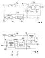
- FIG 15 shows a possible embodiment of a light source 5i which can be used in the distance measuring instrument shown in Figure 1 .
- the light source 5i comprises a signal laser 201 driven by a controller 91i to generate light pulses at a repetition rate determined by controller 91i and which may range, for example, from 1 kHz to 1000 kHz.
- the signal laser 201 may have an output power in a range from 1 to 20 mW, for example. It is, however, also possible to use light sources of a substantially higher output power having peak powers of about 5 W, for example.
- the signal laser may include a temperature stabilization or not.
- the laser light generated by the signal laser is amplified by a two-stage amplifier 203 having a first stage 205 and a second stage 207, wherein each stage comprises a single mode rare earth doped fiber 209 and a wavelength division multiplexer 211.
- the rare earth element used for doping the fiber is erbium in the present example.
- Both the light to be amplified and the pump light are supplied to the doped fibers 205 via the wavelength division multiplexers 211.
- the pump light is generated by a pump laser 213 and supplied to the wavelength division multiplexers 211 of stages 205 and 207 via a beam splitter 215.
- an optical filter 217 is provided between the two stages 205 and 207.
- the filter 217 may include an optical isolator, a wavelength filter and a time gating device, such as an acousto optic modulator, an electro optic modulator and a saturable absorber.
- the filter 217 is a narrowband wavelength filter and an optical isolator.
- the light is amplified in a single mode rare earth doped fiber, wherein the pump light is supplied into the fiber via a wavelength division multiplexer. It is also possible to use double clad fibers having a single mode rare earth doped core included in a clad to which the pump light is supplied. The pump light then enters the core on the clad.
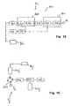
- FIG 16 schematically illustrates a further embodiment of a light source 5j which can be used in the instrument illustrated in Figure 1 .
- the light source 5j in Figure 16 comprises a signal laser 201j generating output light which is supplied to a port 1 of a circulator 221. This light is outputted from a port 2 of the circulator 221 to be supplied to a rare earth doped fiber 209j.
- An amplified signal emitted from the fiber 209j traverses a wavelength division multiplexer 221j and is reflected from a combined filter and mirror 223 such that it again traverses the wavelength division multiplexer 221j to be further amplified in a doped fiber 209j.
- the further amplified light enters the circulator 221 at its port 2 and exits the circulator 221 at its port 3 to form measuring light 9j which can be emitted towards an object.
- the doped fiber 209 is pumped with light from a pump laser 213j which is coupled into the fiber via the wavelength division multiplexer 221j.
Description
- The present invention relates to a distance measuring instrument and a distance measuring method.
- In particular, the invention relates to a distance measuring instrument and method where modulated measuring light is emitted towards an object and wherein measuring light received back from the object is detected and analyzed. A value representing a distance from the object is determined based on such analysis.
- A conventional distance measuring instrument comprises a laser generating pulses of measuring light, and optics to direct the pulses of measuring light towards an object. Pulses of measuring light received back from the object are supplied to a light sensor to generate electrical signals corresponding to the light pulses, and the electrical pulse signals are amplified and analyzed. The analysis includes determination of occurrence times between subsequent pulses to determine the distance from the object based on the determined occurrence times.
- It has been found that the conventional distance measuring instruments and methods could be improved with respect to at least one of measurement accuracy, measurement speed and distance measuring range.
-
US 2005/0094238 A1 discloses a distance measuring instrument comprising a light source, a light detector, optics configured to direct measuring light emitted from the light source towards an object and to direct measuring light received back from the object to the detector, a first signal analyser, a second signal analyser, and a variable gain amplifier, wherein an output of the light sensor is connected to an input of the variable gain amplifier, and output of the variable gain amplifier is connected to a signal input of the first signal analyzer, an output of the first signal analyzer is connected to a gain setting input of the variable gain amplifier, an output of the variable gain amplifier is connected to an input of the second signal analyzer, and wherein the second signal analyzer is configured to determine occurrence times of a predetermined signal feature of signals supplied to its input relative to emission times of pulses of measuring light directed to the object. -
EP 0 848 495 A2 - It is an object of the present invention to improve the distance measuring instrument known from
US 2005/0094238 A1 such that detected light pulses are amplified using a gain adapted to an amplitude of the respective light pulses, and to provide a distance measuring system in which a higher number of light pulses are useful for distance measurement. - This object is solved by providing a distance measuring instrument as defined in appended
claim 1 and a distance measuring method as defined in appendedclaim 10. - Advantageous embodiments are defined in the dependent claims.
- According to an embodiment of the invention, the distance measuring instrument comprises a variable gain amplifier for amplifying a detected signal, wherein a higher gain is applied when the detected signal has a low intensity and wherein a relatively lower gain -is applied when the detected signal has a relatively higher intensity.
- According to a further embodiment of the present invention, the distance measuring instrument comprises a first analyzer for analyzing the detected signal such that the gain of the variable gain amplifier can be set based on a result of this analysis.
- According to a further embodiment, the distance measuring instrument comprises a signal delay module for delaying a first portion of a detected signal, wherein a first analysis of a second portion of the detected signal is performed while the first portion is delayed. According to an embodiment herein, it is then possible to derive a gain value from the analyzed second portion of the detected signal, and to supply the derived gain value to the variable gain amplifier such that the gain of the variable gain amplifier is set when the delayed first portion of the detected signal arrives for amplification. The variable gain amplifier will then amplify the detected signal according to the currently supplied gain value.
- In particular embodiments, the gain value is determined such that the amplified signal outputted from the variable gain amplifier has a substantially constant intensity which is relatively independent of the intensity of the detected signal. The amplified signal can then be subject to further analysis, wherein this analysis is relatively independent of the intensity of the original detected signal. This can be of a particular advantage in practice since measuring light received back from the object and the corresponding detected signals may vary by many orders of magnitude, depending on the distance of the object from the measuring instrument and on an albedo of the object.
- According to an exemplary embodiment of the invention, a distance measuring instrument comprises at least one light source; at least one light detector; optics to direct measuring light emitted from the at least one light source towards an object and to direct measuring light received back from the object to the at least one detector; a signal delay module; a first signal analyzer; and a variable gain amplifier; wherein: an output of the at least one light sensor is connected to an input of the signal delay module; the output of the at least one light sensor is connected to a signal input of the first signal analyzer; an output of the signal delay module is connected to a signal input of the variable gain amplifier; and an output of the first signal analyzer is connected to a gain setting input of the variable gain amplifier.
- As used in the context of this application, the term connected is not limited to mean directly connected but shall also encompass functional connections with intermediate components. For example, if an output of a first component is connected to an input of a second component this comprises a direct connection wherein an electrical conductor directly supplies an outputted signal from the first component substantially unchanged to the input of the second component, and this also comprise that the connection is via one or more additional components, such as an intermediate amplifier or filter which modifies the signal outputted from the first component before it is inputted to the second component. Still, the connection is a functional connection in that, if the signal outputted from the first component undergoes gradual or prompt changes, a corresponding and maybe modified change will be applied to the input of the second component.
- According to exemplary embodiments of the invention, the signal delay module delays an inputted signal by a predetermined signal delay time before it is outputted. The signal delay time can be greater than or equal to one of a processing time associated with the first signal analyzer, a settling time associated with the variable gain amplifier, and a sum of the processing time of the first signal analyzer and the settling time of the variable gain amplifier.
- The processing time associated with the first signal analyzer is defined in the context of the present invention as the time elapsed from the application of an ideal instantaneous step signal to the input of the first signal analyzer to a time at which the output of the first signal analyzer has entered and remained within a value range between 0.5 to 1.5 times the final value established at the output of the first signal analyzer.
- Similarly, the settling time associated with the variable gain amplifier is defined in the context of the present invention as the time elapsed from supplying the settled output from the first signal analyzer to the variable gain amplifier and a time when the variable gain amplifier has adjusted its amplification to its final value with an accuracy within 0.5 to 1.5 times the final value of the adjusted amplification.
- According to exemplary embodiments, the signal delay time is greater than one of 0.5 ns, 1.0 ns, 3 ns, 5 ns and 7 ns.
- According to exemplary embodiments, the first signal analyzer is configured to provide an output signal at its output which is indicative of an intensity of an input signal supplied to its signal input. For example, the output signal can be indicative of a peak value of the input signal, wherein a maximum amplitude of the input signal may represent the peak value. However, other values, such as an integrated energy and other suitable values, can be determined by the first signal analyzer to be indicative of the intensity or other characteristics of the input signal.
- According to an exemplary embodiment, the variable gain amplifier is an analog amplifier. In an exemplary embodiment herein, the variable gain amplifier comprises a divider circuit.
- According to other exemplary embodiments, the variable gain amplifier is a digital amplifier. According to exemplary embodiments herein, the variable gain amplifier comprises plural fixed gain amplifiers.
- According to exemplary embodiments, the distance measuring instrument comprises a second signal analyzer having a first signal input connected to an output of the variable gain amplifier. Thus, the second signal analyzer receives the amplified detected signal for further analysis. In particular, the amplified signals may have a substantially normalized intensity such that the analysis performed by the second signal analyzer may be substantially independent of the intensity of the received signal.
- According to exemplary embodiments, the second signal analyzer is configured to determine occurrence times of a predetermined signal feature of signals supplied to its input. For example, the signal feature may be defined as an occurrence where the signal level exceeds a predetermined level. According to an exemplary embodiment, the predetermined level is a fixed level. According to another exemplary embodiment, the predetermined level is a variable level which depends on some other input. For example, the variable level may depend on an output of the first signal analyzer which is indicative of the intensity of the detected signal.
- According to an exemplary embodiment, the second signal analyzer comprises a second signal input connected to the output of the first signal analyzer.
- According to a further embodiment, the second signal analyzer is configured to determine the occurrence times of the signal feature relative to emission times of pulses of measuring light directed to the object.
- According to an exemplary embodiment herein, a portion of the measuring light emitted from the light source is directly incident on the light detector, without being directed to and received back from the object. This portion of measuring light generates a first detected pulse signal which is amplified according to its intensity and analyzed by the second signal analyzer to identify a first occurrence time. Subsequently, the pulse of measuring light received back from the object generates a second detected signal which is amplified according to its intensity and similarly analyzed by the second signal analyzer to determine a second occurrence time. It is then possible to determine a value based on a difference between the first and second occurrence times, wherein this value represents a distance of the object from the measuring instrument.
- According to exemplary embodiments of the invention, the at least one light source may include a high power pulsed diode laser and a pulsed microchip laser.
- According to a further embodiment of the invention, the at least one light source of the distance measuring instrument comprises a signal laser and a light amplifier including at least one fiber doped with a rare earth element such as erbium and ytterbium. The inventors have found that the doped fiber laser has advantages over Q-switched microchip lasers used as light sources in conventional distance measuring instruments. For example, the Q-switched microchip laser does not allow a precise definition of emission times of light pulses, whereas the doped fiber laser allows for an accurate timing of emitted light pulses. For example, it is possible to achieve a definition of emission times of light pulses from the measuring instrument of about 20 ps or 10 ps, for example, when a doped fiber laser is used.
- According to further embodiments of the present invention, a distance measuring method is provided which comprises: emitting a pulse of measuring light towards an object; receiving a pulse measuring light from the object and generating a pulse signal corresponding to the pulse of measuring light received from the object; delaying a first portion of the generated pulse signal for a predetermined time; generating an intensity signal indicative of an intensity of the generated pulse signal, while delaying the first portion of the generated pulse signal; amplifying the delayed first portion of the generated pulse signal using a gain dependent on the generated intensity signal; determining a value representing a distance based on the amplified delayed first portion of the generated pulse signal.
- The foregoing as well as other advantageous features of the invention will be more apparent from the following detailed description of exemplary embodiments of the invention with reference to the accompanying drawings. It is noted that not all possible embodiments of the present invention necessarily exhibit each and every, or any, of the advantages identified herein.
- Figure 1
- is a schematic illustration of functional components of an embodiment of a distance measuring instrument according to the present invention;
- Figure 2, Figure 3
- are schematic illustrations of details of the distance measuring instrument shown in
Figure 1 ; - Figure 4
- illustrates a further embodiment of a first signal analyzer shown in
Figure 1 ; - Figure 5, Figure 6, Figure 7
- are illustrations of further embodiments of a variable gain amplifier shown in
Figure 1 ; - Figure 8
- is an illustration of details of a distance measuring instrument according to a further embodiment;
- Figure 9
- is an illustration of details of a distance measuring instrument according to a further embodiment;
- Figure 10
- is a schematic illustration of detected pulses having different intensities;
- Figure 11
- is an illustration of a further embodiment of the second signal analyzer shown in
Figure 1 ; - Figure 12
- is an illustration of a still further embodiment of the second signal analyzer shown in
Figure 1 ; and - Figure 13,
- is an illustration of details of a distance measuring instrument according to a further embodiment;
- Figure 14
- is an illustration of details of a distance measuring instrument according to a further embodiment;
- Figure 15, Figure 16
- are schematic illustrations of further embodiments of light sources which can be used in the distance measuring instrument shown in
Figure 1 . - In the exemplary embodiments described below, components that are alike in function and structure are designated as far as possible by alike reference numerals. Therefore, to understand the features of the individual components of a specific embodiment, the descriptions of other embodiments and of the summary of the invention should be referred to.
-
Figure 1 is a block diagram schematically illustrating an embodiment of a distance measuring instrument according to the present invention. - The
distance measuring instrument 1 generates and emits measuring light towards aremote object 3 where a portion of the incident measuring light is diffused such that it can be received by theinstrument 1. The measuring light received from the object is analyzed to determine a distance of theobject 3 from theinstrument 1. For this purpose, theinstrument 1 comprises alight source 5 which generates the measuring light,optics 7 to direct the measuring light emitted from thelight source 5 towards theobject 3 and to receive measuring light back from the object. Theinstrument 1 further comprises alight detector 9 for detecting the measuring light received back from theobject 3 and to generate electrical signals corresponding to intensities of the light received back from the detector. - The term measuring light as used in the present application should generally encompass electromagnetic radiation, such as microwave radiation, visible light and invisible light. In the illustrated embodiment, the
light source 5 is a laser, such as a microchip laser, a doped fiber laser or other suitable laser.Light 9 emitted from the laser enters a prism 11 which includes a partiallyreflective surface 13 and amirror surface 14. Asmall monitoring portion 10 of the emittedlight 9 is reflected from partiallyreflective surface 13 to be incident on amirror surface 14 which directs thatportion 10 onto thedetector 9. - The
instrument 1 further comprises an analyzer andcontrol system 21 for analyzing the detected measuring light, determining measuring results and controlling the whole instrument. - The monitoring
portion 10 of the emittedlight 9 is directed to the detector to allow the analyzing andcontrol system 21 to monitor the emitted measuring light. For example, the analyzing andcontrol system 21 may determine occurrence times of particular features of thatportion 10 which are relevant for the distance measurement. For example, a start time of a distance measurement can be determined based on the detection and analysis of the monitoringportion 10 of the light 9 emitted from thelight source 5. Alarger portion 17 of the light 9 emitted from thesource 5 traverses the partiallyreflective surface 13 and is reflected from amirror surface 15, andsurface 13 and is reflected from amirror surface 15, and further reflected from amirror 18 such that the measuring light reflected frommirror 18 is directed along an optical axis 22 of alens 23. Thelens 23 is schematically represented inFigure 1 as a single lens element. In practice, however, thelens 23 may include plural lens elements to form an objective lens suitable to direct the measuring light along the optical axis 22 towards theobject 3. For this purpose, thelens 23 may have functions for focusing the measuring light ontoobjects 3 at variable distances. A cross section oflens 23 is larger then necessary to emit the measuring light towards the object, wherein the exceeding portion of the cross section is used for receiving measuring light 25 reflected back from theobject 23 and for directing this measuring light 25 onto thedetector 9. - In the exemplary embodiment shown with reference to
Figure 1 , a portion of the light pulse directed to the object is branched off byreflective surfaces detector 9 which is the same detector which also receives the light pulse reflected back from the object. Thus, both the start time and the stop time of the distance measurement are derived from light pulses incident on thesame detector 9. In other embodiments, the start time of the distance measurement is determined by other principles. For example, the instrument may comprise an additional light detector, such as a PIN diode to receive a portion of the light pulse emitted towards the object. The start time of the distance measurement can then be generated based on output signals of such additional detector. - Further, it is possible to determine the start time of the distance measurement directly from an occurrence time of a trigger signal for emitting light pulses from the light source. To take into account possible time delays and offsets in determination of the start time, it is possible to calibrate the instrument relative to an object disposed at a known distance from the instrument, for example.
- The
detector 9 generally includes a sensor portion receiving the incident light and a circuit portion to generate electrical signals corresponding to intensities of the incident light. Thedetector 9 may include an amplifier for adjusting a signal level and impedance of the generated electrical signal such that it is suitable for subsequent analysis by the analyzer andcontrol system 21. - The analyzing and
control system 21 comprises ananalyzer 31 for analyzing shapes or characteristics of the electrical signals provided at theoutput 29 ofdetector 9. However, intensities of the signals outputted from thedetector 9 may vary by plural orders of magnitude depending on a distance of theobject 3 from theinstrument 1 and on an albedo of theobject 3. The signals provided by thedetector 9 have a very high dynamic range, accordingly, whereas theanalyzer 31 has a limited dynamic range determined by a configuration of theanalyzer 31. Therefore, the analyzer andcontrol system 21 comprises avariable gain amplifier 33 configured to amplify signals provided by thedetector 9 with a suitable gain such that the amplified signal has intensities within a reduced dynamic range suitable for analysis byanalyzer 31. Anoutput 35 of thevariable gain amplifier 33 is connected to afirst signal input 36 ofanalyzer 31. - The term variable gain amplifier as used in the present invention should not be limited to amplifiers having always gains larger than 1 such that a signal level outputted from the
output 35 of the variable gain amplifier is always greater than a signal level of a signal supplied to asignal input 37 of thevariable gain amplifier 33. The gain of the variable gain amplifier may be set to values less than 1, accordingly. - The analyzer and
control system 21 comprises asignal analyzer 41 for determining the gain used by thevariable gain amplifier 33 wherein a signal representing the gain is outputted from anoutput 42 of thesignal analyzer 41 and supplied to again setting input 43 of thevariable gain amplifier 33. Asignal input 45 of thesignal analyzer 41 is connected to theoutput 29 of thedetector 9 such that thesignal analyzer 41 receives a portion of the detection signal generated by thelight detector 9. Thesignal analyzer 41 is configured to determine the gain based on a characteristic of the output signal, such as an intensity of the output signal of thelight detector 9. For this purpose, thesignal analyzer 41 has to process the inputted signal. Such processing will take a certain amount of processing time depending on the configuration of thesignal analyzer 41. The signal representing the gain to be applied by thevariable gain amplifier 33 will be available at theoutput 42 ofsignal analyzer 41 at a time which is later than an arrival time of the signal at thesignal input 45 ofsignal analyzer 41. Further, when the signal representing the gain is available at theoutput 42 ofsignal analyzer 41 and supplied to thegain setting input 43 of thevariable gain amplifier 33, thevariable gain amplifier 33 will need a certain amount of time depending on the configuration of the variable gain amplifier until the gain of the amplifier is precisely adjusted according to the inputted gain value. This amount of time is referred to as the settling time of thevariable gain amplifier 33. It follows that thevariable gain amplifier 33 is ready for amplification of a given detection signal at a point in time which is later than a time at which the signal to be amplified with the variable gain is available at theoutput 29 of thedetector 9. - Therefore, in the illustrated example, the signal input of the
variable gain amplifier 33 is not directly connected to theoutput 29 of thelight detector 9, and asignal delay module 51 is arranged in a signal path between thelight detector 9 and thevariable gain amplifier 33. In more detail, thedelay module 51 has asignal input 52 which is connected to theoutput 29 of thelight detector 9, and asignal output 53 of thedelay module 51 is connected to thesignal input 37 of thevariable gain amplifier 33. The delay module is configured to receive a given signal at itsinput 52 and to make a substantially same or similar signal available at itsoutput 53 wherein the outputted signal is delayed relative to the inputted signal by a predetermined delay time. Thedelay module 51 may comprise, for example, a delay line, a surface acoustic wave device or other device suitable for delaying an inputted signal by a predetermined amount of time. In the illustrated example, the delay time of the delay module is selected such that it is greater than a sum of the processing time of thesignal analyzer 41 and the settling time of thevariable gain amplifier 33. By such arrangement it is possible to complete the setting of the gain of thevariable gain amplifier 33 until the signal to be amplified with the set gain arrives at thesignal input 37 of thevariable gain amplifier 33. For example, if thesignal analyzer 41 is configured such that it has a processing time of 3 ns and if thevariable gain amplifier 33 is configured such that it has a settling time of 2 ns, the delay module is designed such that it has a delay time of 5 ns or 6 ns or more. - As mentioned above, the
signal analyzer 41 is configured to determine an intensity of a signal supplied to itsinput 45. In the illustrated embodiment, thesignal analyzer 41 is configured such that it detects a peak amplitude of the signal supplied to itsinput 45 as the signal intensity. Further, thesignal analyzer 41 has areset input 55 to which a predefined signal can be applied for resetting the signal analyzer such that it starts to analyze a next signal supplied to itssignal input 45. For example, if the signal to be analyzed is a pulse shape, thesignal analyzer 41 can determine the intensity of the pulse or, in the given example, determine the peak value of the pulse, and provide a corresponding signal at itsoutput 42. A level of that signal representing the gain to be used by thevariable gain amplifier 33 will be maintained constant until thesignal analyzer 41 is reset by supplying the reset signal to itsreset input 55. Thereafter, thesignal analyzer 41 is prepared to analyze the intensity of a next pulse signal supplied to itssignal input 45. - A configuration of the
signal analyzer 41 and thevariable gain amplifier 33 is shown in more detail inFigure 2 . -
Figure 2 is a schematic illustration of components of a portion of the analyzer andcontrol system 21. In the illustrated example, the variable gain amplifier comprises an x/y divider 61, wherein the x input of the x/y divider 61 is connected to thesignal input 37 of the variable gain amplifier and wherein the y input of the x/y divider 61 is connected to thegain setting input 43 of thevariable gain amplifier 33. As shown inFigure 2 , it is possible to provide a fixedgain amplifier 63 in the signal path between theoutput 53 of thedelay module 51 and the x input of the x/y divider. A signal output of the x/y divider is connected to or provides theoutput 35 of the variable gain amplifier. - The
signal analyzer 41 comprises a high speed peak detector and holdmodule 67 having a signal input S providing thesignal input 45 of thesignal analyzer 41, a reset input R providing thereset input 55 of thesignal analyzer 41, and an output O which is connected to a first signal input S1 of ananalog MAX module 69 which outputs the maximum of the two signals supplied to its inputs S1 and S2. The input S2 is used to supply a signal Sf to thesignal analyzer 41, wherein the signal Sf represents a maximum gain to be applied to thevariable gain amplifier 33. - An output O of the
MAX module 69 is connected to a first signal input S1 of aMUX analog module 71 which further includes a second signal input S2, a signal output O and a choice input C. The MUX module is configured to output one of the two signals supplied to its inputs S1 and S2 depending on a choice signal supplied to its choice input C. - In a first mode, where a choice signal selects input S2 as the output of the
MUX module 71, a fixed gain corresponding to a level Vg can be supplied to input S2 of theMUX module 71 to set the gain of thevariable gain amplifier 33 to a value represented by level Vg. The gain of the x/y divider 61 is then set to 1/Vg, which is independent on the intensity of the signal S supplied to theinput 45 of thesignal analyzer 41. This mode effectively disables thesignal analyzer 41 and can be used when the adaptive amplification of the inputted signals S depending on their intensities is not desired. - In a second mode, where the choice signal is selected such that input S1 of
MUX module 71 is selected for output, the intensity analyzing operation of thesignal analyzer 41 is enabled wherein the gain value provided atoutput 42 ofsignal analyzer 41 depends on the intensity of the signal S supplied to theinput 45. However, a maximum gain can be set by supplying a signal level Sf representing the maximum gain to the S2 input of theMAX module 69. -
Figure 3 is a more detailed illustration of further components of the analyzer andcontrol module 21. As shown inFigure 3 , thesignal analyzer 31 comprises a fast analogdigital converter 75 having ananalog input 76 which receives the amplified signal S/S0 from theoutput 35 of thevariable gain amplifier 33, where S0 is theoutput 42 of theanalyzer 41, for example the maximum amplitude of the signal S. The analogdigital converter 75 is driven by aclock 81 such that the signal level supplied to theinput 76 is sampled according to a rate determined by theclock 81, and digital values representing the signal level supplied to theinput 76 are made available at anoutput 77 of the analog digital converter according to the rate determined by theclock 81. These digital values are then written into amemory 83 at addresses selected by anaddress generator 85. Also theaddress generator 85 is driven by theclock 81 such that the address selected by theaddress generator 85 is advanced according to the rate determined by theclock 81. Thus, subsequent digital readings of the analog input signal are stored in subsequent memory locations. Thememory 83 is accessible from a controller 91 which can be any suitable computing device or network of devices such as personal computers or other hardware. - The controller 91 can be connected to user interface devices, such as a
display 92 and akeyboard 93, or other suitable user interfaces such as touch screens, for example. - The controller 91 accessing the
memory 83 can perform an analysis of the recorded digital values. For example, the controller may determine features of the digitized signal, such as occurrences of signal values exceeding a threshold or a center of gravity of a digitized pulse signal. - The controller 91 may also calculate a time when the determined signal feature occurred. Further, if there are two subsequent digitized pulses stored in the memory, the controller can determine the centers of gravity of both signals in terms of memory addresses and then calculate a temporal distance between the occurrence of two pulses based on a rate of the
clock 81 advancing theaddress generator 85. Assume that a first one of such two digitized pulses stored in memory corresponds to themonitoring portion 10 of alight pulse 9 emitted by thelight source 5 and incident directly onto thelight detector 9 whereas the second of such digitized light pulses stored in memory corresponds to theportion 17 of the emitted light pulse directed to and received back from theobject 3, then the temporal distance between the two analyzed signals represents the distance of theobject 3 from the measuringinstrument 1, wherein the distance of the object can be calculated as the temporal distance times the speed of light divided by two. - The distance measuring instrument as shown in
Figure 1 further comprises anactuator 95 driven by the controller 91 for changing an orientation of the optical axis 22 ofoptics 7. For example, theoptics 7,light source 5 anddetector 9 can be arranged as a module which is rotatable relative to a stand placed on the ground about a horizontal axis and a vertical axis. The controller 91 can then drive theactuator 95 such that theobject 3 is scanned with measuring light wherein the distance of subsequent scan points of theobject 3 from the measuringinstrument 1 is determined as illustrated above. The resulting data, also refer to as a point cloud, can be stored by the controller 91 for further analysis in a memory, such as a hard disc 97 shown inFigure 1 . - Further exemplary embodiments of the present invention will be described below.
-
Figure 4 is a schematic illustration of a portion of an analyzer and control system 21a of a distance measuring instrument 1a which can be of a similar structure as that illustrated with reference toFigure 1 above. A signal analyzer 41a shown inFigure 4 provides the combined functions of a high speed peak detector and hold module and MAX module as represented by a functional box 41' shown in broken lines inFigure 2 . The signal analyzer 41a comprises again 1 buffer, for example anoperational amplifier 101 having a non-inverted input which is supplied with the input signal S via anideal diode 103, and an inverted input which is supplied with a feedback from its output. Ahold capacitor 105 is connected to the non-inverting input of theoperational amplifier 101 and is charged with a voltage Sf representing the maximum gain upon operation of areset switch 107. -
Figure 5 shows an exemplary embodiment of a variable gain amplifier 33b of an analyzer and control system 21b of a distance measuring instrument 1b which can be similar in structure to that shown inFigure 1 . The variable gain amplifier 33b comprises an xy multiplier 111 having a X input which is supplied with the signal S to be amplified via a constant gain amplifier 63b, wherein it is also possible to omit the amplifier 63b and directly supply the signal S to be amplified to the X input of the xy multiplier. Anoperational amplifier 113 receives the signal S0 representing the reciprocal gain at its inverting input via a resistor, and a non-inverting input ofoperational amplifier 113 is connected to ground. An output of theoperational amplifier 113 provides the output O of the variable gain amplifier 33b at an output 35b, wherein the output of theoperational amplifier 131 is also connected to the Y input of the xy multiplier 111. An output of the xy multiplier is supplied as a feedback via a resistor R to the inverting input ofoperational amplifier 113. -
Figure 6 is a schematic illustration of a further embodiment of a variable gain amplifier 33c which may have an improved bandwidth, in particular for low levels of input signal S, as compared to the embodiment shown inFigure 5 . The variable gain amplifier 33c comprises anxy multiplier 121 having an X input supplied with the signal S to be amplified via a fixed gain amplifier 63c, and an Y input connected to an output of axy divider 123. The xy divider has an X input supplied with a constant signal (represented as "1" inFigure 6 ), and an Y input supplied with the reciprocal gain S0. -
Figure 14 is a schematic illustration of a further embodiment of a variable gain amplifier 331 which is a variation of the variable gain amplifier shown inFigure 6 . In the variable gain amplifier 331 shown inFigure 14 , an Y input of a multiplier 1211 is connected to an output of amultiplier 261 which receives its x and y inputs from outputs ofdifferential amplifiers 263und 265. Such arrangement allows to shape the divider function by constants a, b and c supplied to thedifferential amplifiers multiplier 261. It is further possible to provide further additional combinations of multipliers and differential amplifiers to increase the number of constants a, b, c, ... for shaping the divider function. -
Figure 7 shows a further embodiment of avariable gain amplifier 33d which could be used in the distance measuring instrument shown inFigure 1 . Thevariable gain amplifier 33d comprises anxy multiplier 127 having an X input supplied with the signal S to be amplified, and an output which is connected to an X input of a further xy multiplier 129. An output of the xy multiplier 129 provides the output of thevariable gain amplifier 33d. The reciprocal gain S0 is supplied to the input of asquare rooter 131, and an output of thesquare rooter 131 is connected to an Y input of axy divider 133. A constant signal (represented by "1" inFigure 7 ) is supplied to an X input of xydivider 133. An output of thexy divider 133 is connected to Y inputs of bothxy multipliers 127 and 129. -
Figure 8 illustrates a portion of a further embodiment of an analyzer and control system 21e which could be used in a distance measuring instrument according to an embodiment of the invention. In the embodiment shown inFigure 8 , a signal analyzer 41e and avariable gain amplifier 33e are implemented using digital electronics. The signal analyzer 41e comprises an analog digital converter 141 supplied with the signal S generated by a light detector. The signal is digitized by the analog digital converter 141 and supplied as a digital signal to amaximum encoder 143 which provides a maximum value of the received digital values at an output 42e of the signal analyzer 41e. - The
variable gain amplifier 33e comprises a digitalvariable gain amplifier 151 having a signal input which is supplied with the signal to be amplified from adelay module 51e. The digital representation of the peak signal provided at the output 42e of the signal analyzer 41e can be directly supplied to a digital gain input of digitalvariable gain amplifier 151. In the embodiment shown inFigure 8 , a look-up table 153 is provided to receive the representation of the peak value and to translate this peak value to a gain which is supplied to the digital gain input of the digitalvariable gain amplifier 151. The look-up table is prepared in advance to take possible non-linear effects of the digitalvariable gain amplifier 151 into account or to achieve a desired further variation of the gain to be applied for amplification of the signal S based on the peak value detected by signal analyzer 41e. -
Figure 9 is a schematic illustration of a portion of an analyzer and control system 21f according to a still further embodiment of the present invention. Asignal analyzer 41f of system 21f comprises an array of plural high speed comparators and latches 161. For example, a number of the comparators and latches may be six. Each of the comparators and latches is supplied with the signal S to be analyzed, and thesignal analyzer 41f further comprises an array of pluralmaximum encoders 163, wherein each maximum encoder is connected to a corresponding latch of the array of comparators and latches 161. The outputs of the pluralmaximum encoders 163 form a digital representation of the analyzed signal S. These outputs of themaximum encoder 163 also drive a corresponding number of high speed turn on/off switchedamplifiers 33f such that an output 35f thereof provides the delayed and amplified signal S wherein the gain applied for amplification is dependent on a peak level of the signal S. - Reference is now made to
Figure 1 , wherein thesignal analyzer 31 is generally configured to determine occurrence times of signal features of the signal S generated by thelight source 9. -
Figure 10 is a schematic illustration of possible temporal pulse shapes of signal S.Figure 10a shows apulse 171 of a relatively small peak value, whereasFigure 10b shows a pulse 172 of a relatively higher peak value. An occurrence time of the signal speaks is indicated by tp. Since it is not easily possible to determine the occurrence times tp of the peak values, thesignal analyzer 31 can be configured to determine occurrence times tf of features different from the occurrence times tp of the peak values. For example, the occurrence times tf can be defined as those times when the signal exceeds a predetermined constant threshold Lc. It is apparent that the times tf occur earlier than the peak times tp wherein a difference tp - tf depends on the intensity of the signal. It is desirable to determine feature times tf which are indicative of the occurrence times of the peak values tp independently of the intensity of the signals. -
Figure 11 illustrates an embodiment of a signal analyzer 31g which could be used in the distance measuring instrument illustrated inFigure 1 . The signal analyzer 31g comprises a veryfast comparator 181 having a first input receiving the signal to be analyzed from a delay module (not shown inFigure 11 ), and having a second input connected to an output of amultiplier 183.Multiplier 183 has an input connected to asecond signal input 185 of the signal analyzer 31g and which is connected to an output ofsignal analyzer 41 and representing the gain to be applied by thevariable gain amplifier 33. The multiplier is configured to multiply the signal supplied to its input by a fixed factor, such as 0.5 in the illustrated example. An output Sd of thecomparator 181 may then provide a step-shaped signal which changes value when the signal supplied atinput 36g exceeds the signal supplied atinput 85 and multiplied by the fixed factor. The occurrence time of change of value of the signal Sd can then be used as the feature time tf of the analyzed signal, and such feature time tf is a better representation of the occurrence time tp of the peak value of the signal at varying signal intensities as compared to using a constant threshold as illustrated inFigure 10 above. - Reference is now made to
Figure 3 : The signal analyzer shown inFigure 3 further comprises an analogdigital converter 187 to translate the analog value provided bysignal analyzer 41 and which represents the gain applied to the variable gain amplifier into a digital value. This digital value is accessible by the controller 91 and can be taken into account when the occurrence times of the signals are determined by the controller 91. -
Figure 12 illustrates a further embodiment of asignal analyzer 31h which has a configuration similar to that shown inFigure 11 in that multipliers 183a are connected to inputs of vary fast comparators 181a. The other inputs of the vary fast comparators 181a are all supplied with the amplified signal to be analyzed. However, an array of multipliers 183a andcomparators 181h is provided, wherein the multipliers 183a are configured to multiply their input signals with different fixed vectors x1,..., xi, ..., xn. Outputs Sd1,..., Sdi,..., Sdn represent occurrence times of different features of the analyzed signals, wherein the different occurrence times are those times where the signal exceeds different signal levels determined by the multiplication factors xi of themultipliers 183h. This allows to analyze the occurrence times at different levels of the signal, wherein the signal noise will be different at different signal levels. The possibility of analyzing the signal at different levels may then improve the total accuracy. -
Figure 13 illustrates a further embodiment of components of an analyzing andcontrol system 21k which can be used in embodiments of the distance measuring instrument. - The analyzing and
control system 21k comprises asignal analyzer 41k for determining the gain to be used for amplifying a signal S as supplied to both thesignal analyzer 41k and adelay module 51k. The arrangement of components shown inFigure 13 is similar to that shown inFigure 2 , wherein a variable gain amplifier 33k is embodied as a multiplier 111k. However, in the arrangement shown inFigure 13 ,baluns 251 are connected to an output 42k of thesignal analyzer 41k and anoutput 53k of thedelay module 51k, respectively, for supplying the respective signals to the multiplier 111k via two symmetric lines. Further, alevel shifter 253 is provided in the symmetric line between the output 42k of thesignal analyzer 41k and an input of the multiplier 111k. Afurther balun 251 is connected to the symmetric line output of the multiplier 111k such that anoutput 35k of the amplified signal is again on an asymmetric line. -
Figure 15 shows a possible embodiment of a light source 5i which can be used in the distance measuring instrument shown inFigure 1 . The light source 5i comprises asignal laser 201 driven by a controller 91i to generate light pulses at a repetition rate determined by controller 91i and which may range, for example, from 1 kHz to 1000 kHz. Thesignal laser 201 may have an output power in a range from 1 to 20 mW, for example. It is, however, also possible to use light sources of a substantially higher output power having peak powers of about 5 W, for example. The signal laser may include a temperature stabilization or not. - The laser light generated by the signal laser is amplified by a two-
stage amplifier 203 having afirst stage 205 and asecond stage 207, wherein each stage comprises a single mode rare earth dopedfiber 209 and awavelength division multiplexer 211. The rare earth element used for doping the fiber is erbium in the present example. - Both the light to be amplified and the pump light are supplied to the doped
fibers 205 via thewavelength division multiplexers 211. The pump light is generated by apump laser 213 and supplied to thewavelength division multiplexers 211 ofstages second stage 207, anoptical filter 217 is provided between the twostages filter 217 may include an optical isolator, a wavelength filter and a time gating device, such as an acousto optic modulator, an electro optic modulator and a saturable absorber. In the present example, thefilter 217 is a narrowband wavelength filter and an optical isolator. - In the embodiment illustrated with reference to
Figure 15 above, the light is amplified in a single mode rare earth doped fiber, wherein the pump light is supplied into the fiber via a wavelength division multiplexer. It is also possible to use double clad fibers having a single mode rare earth doped core included in a clad to which the pump light is supplied. The pump light then enters the core on the clad. - While the embodiment of the light source illustrated with reference to
Figure 15 above includes a two stage amplifier, it is also possible to use light sources having more than two amplification stages. -
Figure 16 schematically illustrates a further embodiment of alight source 5j which can be used in the instrument illustrated inFigure 1 . Thelight source 5j inFigure 16 comprises a signal laser 201j generating output light which is supplied to aport 1 of acirculator 221. This light is outputted from aport 2 of thecirculator 221 to be supplied to a rare earth doped fiber 209j. An amplified signal emitted from the fiber 209j traverses awavelength division multiplexer 221j and is reflected from a combined filter andmirror 223 such that it again traverses thewavelength division multiplexer 221j to be further amplified in a doped fiber 209j. The further amplified light enters thecirculator 221 at itsport 2 and exits thecirculator 221 at itsport 3 to form measuring light 9j which can be emitted towards an object. - The doped
fiber 209 is pumped with light from a pump laser 213j which is coupled into the fiber via thewavelength division multiplexer 221j. - While the invention has been described with respect to certain exemplary embodiments thereof, it is evident that many alternatives, modifications and variations will be apparent to those skilled in the art. Accordingly, the exemplary embodiments of the invention set forth herein are intended to be illustrative and not limiting in any way. Various changes may be made without departing from the scope of the present invention as defined in the following claims.
Claims (14)
- A distance measuring instrument comprising:at least one light source (5);at least one light detector (9);optics (7) configured to direct measuring light emitted from the at least one light source (5) towards an object (3) and to direct measuring light received back from the object to the at least one light detector (9);a first signal analyzer (41);a second signal analyzer (31);a variable gain amplifier (33);wherein:an output (29) of the at least one light detector (9) is connected to a signal input (45) of the first signal analyzer (41);an output (42) of the first signal analyzer (41) is connected to a gain setting input (43) of the variable gain amplifier (33);an output (35) of the variable gain amplifier (33) is connected to a first input (36) of the second signal analyzer (31);wherein the second signal analyzer (31) is configured to determine occurrence times of a predetermined signal feature of signals supplied to its first input (36) relative to emission times of pulses of measuring light directed to the object (3);characterized bya signal delay module (51);wherein:the output (29) of the at least one light detector (9) is further connected to an input (52) of the signal delay module (51);an output (53) of the signal delay module (51) is connected to a signal input (37) of the variable gain amplifier (33).
- The distance measuring instrument according to claim 1, wherein the first signal analyzer (41) has at least one of the following features:- it is configured to provide an output signal at its output which is indicative of a peak value of an input signal supplied to its signal input;- it comprises an amplitude detector (67); and- it comprises a reset input (55).
- The distance measuring instrument according to claim 1 or 2, wherein the variable gain amplifier (33) comprises a divider circuit (61; 123, 133), wherein the variable gain amplifier further comprises a first multiplier circuit (121, 125), wherein an output of the divider circuit is connected to a first input of the first multiplier circuit,
wherein the variable gain amplifier (33) further comprises a second multiplier (127), wherein a first input of the second multiplier is connected to the output (53) of the signal delay module, wherein an output of the second multiplier (127) is connected to a second input of the first multiplier (125), wherein the variable gain amplifier further comprises a square rooter (131), wherein an input of the square rooter (131) is connected to an output (52) of the first signal analyzer (51) and an output of the square rooter (131) is connected to a first input of the divider circuit (133). - The distance measuring instrument according to one of claims 1 to 3, wherein the variable gain amplifier comprises a digital variable gain amplifier (151) and a maximum encoder (143) and a look-up-table (153), wherein an output of the maximum encoder (143) is connected to an input of the look-up-table (153) and an output of the look-up-table is connected to a gain setting input of the digital variable gain amplifier (151).
- The distance measuring instrument according to one of claims 1 to 4, wherein the second signal analyzer (31) has at least one of the following features:- it is configured to determine the occurrence time as a time when the signal supplied to the first input of the second signal analyzer exceeds a predetermined level; and- it comprises a first analogue/digital converter (75) configured to generate a series of digital values representing subsequent readings of a signal supplied to the first signal input (36) of the second signal analyzer;- it is configured to process the generated series of digital values based upon an output of the first signal analyzer (41).
- The distance measuring instrument according to one of claims 1 to 5, further comprising a trigger circuit (91) having an output connected to the at least one light source (5), wherein the trigger circuit and the at least one light source are configured to operate the at least one light source such that it emits subsequent pulses of measuring light.
- The distance measuring instrument according to claim 6, wherein the optics (7) is configured to direct a portion of the measuring light emitted from the at least one light source (5) directly to the at least one detector (9), without directing this portion to the object (3).
- The distance measuring instrument according to one of claims 1 to 7, wherein the at least one light source (5) comprises:at least one light guiding fiber (209) doped with a rare earth element,a pump laser (213) connected to the at least one light guiding fiber (209), anda signal laser (201) connected to the at least one light guiding fiber (209),wherein the at least one light guiding fiber (209) is configured to amplify and emit light received from the signal laser (201) as the measuring light.
- The distance measuring instrument according to claim 8, wherein the rare earth element comprises at least one of Ytterbium and Erbium and/ or wherein the at least one light guiding fiber is a double clad fiber having a single mode fiber core.
- A distance measuring method comprising:emitting a pulse of measuring light towards an object;receiving a pulse of measuring light from the object and generating a pulse signal corresponding to the pulse of measuring light received from the object;delaying a first portion of the generated pulse signal for a predetermined time;generating an intensity signal indicative of an intensity of the generated pulse signal, while delaying the first portion of the generated pulse signal;amplifying the delayed first portion of the generated pulse signal using a gain dependent on the generated intensity signal;determining a value representing a distance based on an occurrence time of a signal feature of the amplified delayed first portion of the generated pulse signal relative to a time which depends on an emission time of the pulse of measuring light emitted towards the object.
- The distance measuring method according to claim 10, wherein the generating of the intensity signal includes determining a maximum value of the generated pulse signal.
- The distance measuring method according to claim 10 or 11, wherein the amplifying of the delayed first portion of the generated pulse signal comprises dividing a signal corresponding to the delayed first portion by the intensity signal.
- The distance measuring method according to one of claims 10 to 12, further comprising generating a light pulse, wherein a first portion of the generated light pulse forms the pulse of measuring light emitted towards the object; and
receiving a second portion of the generated light pulse without directing it to the object and generating a pulse signal corresponding to the received second portion of light not directed to the object. - The distance measuring method according to claim 13, wherein a first pulse signal is generated which corresponds to the received second portion of light not directed to the object;
wherein a second pulse signal is generated which corresponds to the pulse of measuring light received from the object; and
wherein the value representing the distance is determined based on a temporal distance between the first and second pulse signals.
Applications Claiming Priority (1)
| Application Number | Priority Date | Filing Date | Title |
|---|---|---|---|
| PCT/EP2007/008487 WO2009039875A1 (en) | 2007-09-28 | 2007-09-28 | Distance measuring instrument and method |
Publications (2)
| Publication Number | Publication Date |
|---|---|
| EP2193388A1 EP2193388A1 (en) | 2010-06-09 |
| EP2193388B1 true EP2193388B1 (en) | 2016-03-09 |
Family
ID=39434328
Family Applications (1)
| Application Number | Title | Priority Date | Filing Date |
|---|---|---|---|
| EP07818567.5A Active EP2193388B1 (en) | 2007-09-28 | 2007-09-28 | Distance measuring instrument and method |
Country Status (4)
| Country | Link |
|---|---|
| US (3) | US8149391B2 (en) |
| EP (1) | EP2193388B1 (en) |
| CN (1) | CN101828128B (en) |
| WO (1) | WO2009039875A1 (en) |
Families Citing this family (24)
| Publication number | Priority date | Publication date | Assignee | Title |
|---|---|---|---|---|
| WO2009039875A1 (en) | 2007-09-28 | 2009-04-02 | Trimble 3D Scanning | Distance measuring instrument and method |
| EP2182379B1 (en) * | 2008-10-30 | 2012-09-19 | Sick Ag | Laser scanner to measure distance |
| US9091754B2 (en) | 2009-09-02 | 2015-07-28 | Trimble A.B. | Distance measurement methods and apparatus |
| US8922923B2 (en) | 2011-03-01 | 2014-12-30 | Seagate Technology Llc | Interleaved automatic gain control for asymmetric data signals |
| TWI476364B (en) * | 2011-05-09 | 2015-03-11 | Lin Cho Yi | Detecting method and apparatus |
| US9572682B2 (en) | 2011-09-29 | 2017-02-21 | Arthromeda, Inc. | System and method for precise prosthesis positioning in hip arthroplasty |
| EP2597483B8 (en) * | 2011-11-25 | 2017-06-07 | Safran Vectronix AG | Distance sensor |
| US9157989B2 (en) | 2012-08-29 | 2015-10-13 | Trimble Ab | Distance measurement methods and apparatus |
| WO2014145540A2 (en) | 2013-03-15 | 2014-09-18 | Arthromeda, Inc. | Systems and methods for providing alignment in total knee arthroplasty |
| EP2846173B1 (en) | 2013-09-09 | 2019-06-19 | Trimble AB | Ambiguity compensation in time-of-flight ranging |
| JP6299500B2 (en) * | 2014-01-29 | 2018-03-28 | 株式会社東京精密 | Multipoint distance measuring device and method, and shape measuring device |
| CN106461780B (en) * | 2014-05-28 | 2019-06-18 | 特林布尔有限公司 | The method and apparatus of the range measurement of compensation |
| JP6269334B2 (en) * | 2014-06-12 | 2018-01-31 | 株式会社東京精密 | Multipoint distance measuring device and shape measuring device |
| US9812486B2 (en) * | 2014-12-22 | 2017-11-07 | Google Inc. | Time-of-flight image sensor and light source driver having simulated distance capability |
| CN104777470A (en) * | 2015-03-20 | 2015-07-15 | 中国科学院合肥物质科学研究院 | Circuit for expanding range of pulse laser short-range dynamic gain |
| CN106160706A (en) * | 2015-04-24 | 2016-11-23 | 南京理工大学 | A kind of dual pathways moment discrimination circuit |
| JP7165587B2 (en) * | 2016-06-01 | 2022-11-04 | ベロダイン ライダー ユーエスエー,インコーポレイテッド | Multi-pixel scanning LIDAR |
| EP3330741B1 (en) * | 2016-12-05 | 2019-02-13 | Sick Ag | Optoelectronic sensor and method for detecting objects in a surveillance area |
| US10139478B2 (en) * | 2017-03-28 | 2018-11-27 | Luminar Technologies, Inc. | Time varying gain in an optical detector operating in a lidar system |
| CN107356937A (en) * | 2017-08-25 | 2017-11-17 | 长春德信光电技术有限公司 | A kind of walking robot collision warning device based on Laser Detection Technique |
| EP3489719B1 (en) | 2017-11-23 | 2023-09-20 | Trimble AB | Improved electronic distance meter |
| JP7013925B2 (en) * | 2018-02-23 | 2022-02-01 | 株式会社デンソー | Optical ranging device and its method |
| DE102018129246B4 (en) * | 2018-11-21 | 2020-10-15 | Infineon Technologies Ag | INTERFERENCE DETECTION AND REDUCTION FOR LIDAR SYSTEMS |
| CN113093202A (en) * | 2021-03-09 | 2021-07-09 | 南京理工大学 | Digital full-waveform laser radar system |
Citations (2)
| Publication number | Priority date | Publication date | Assignee | Title |
|---|---|---|---|---|
| FR2562283A1 (en) * | 1984-04-03 | 1985-10-04 | Lmt Radio Professionelle | Circuit for regulating the level of pulse peaks operating pulse by pulse |
| US20030181179A1 (en) * | 2002-03-25 | 2003-09-25 | Hooman Darabi | Analog power detection for gain control operations |
Family Cites Families (7)
| Publication number | Priority date | Publication date | Assignee | Title |
|---|---|---|---|---|
| US4373804A (en) * | 1979-04-30 | 1983-02-15 | Diffracto Ltd. | Method and apparatus for electro-optically determining the dimension, location and attitude of objects |
| US4856899A (en) * | 1985-12-20 | 1989-08-15 | Yokogawa Electric Corporation | Optical frequency analyzer using a local oscillator heterodyne detection of incident light |
| JPH10173456A (en) | 1996-12-11 | 1998-06-26 | Fujitsu Ltd | Signal amplifier circuit |
| US6439460B1 (en) * | 2000-12-15 | 2002-08-27 | Yu-Chun Chang | Instant synchronous automatic gain control apparatus |
| US6594000B2 (en) * | 2001-01-25 | 2003-07-15 | Science And Technology Corporation | Automatic gain control system for use with multiple wavelength signal detector |
| FI20020279A0 (en) | 2002-02-12 | 2002-02-12 | Juha Tapio Kostamovaara | Procedure and arrangement for performing triggering and timing of triggering |
| WO2009039875A1 (en) | 2007-09-28 | 2009-04-02 | Trimble 3D Scanning | Distance measuring instrument and method |
-
2007
- 2007-09-28 WO PCT/EP2007/008487 patent/WO2009039875A1/en active Application Filing
- 2007-09-28 EP EP07818567.5A patent/EP2193388B1/en active Active
- 2007-09-28 CN CN2007801008598A patent/CN101828128B/en active Active
-
2010
- 2010-03-24 US US12/731,048 patent/US8149391B2/en active Active
-
2012
- 2012-03-09 US US13/416,814 patent/US8514376B2/en active Active
-
2013
- 2013-08-15 US US13/968,216 patent/US9605955B2/en active Active
Patent Citations (2)
| Publication number | Priority date | Publication date | Assignee | Title |
|---|---|---|---|---|
| FR2562283A1 (en) * | 1984-04-03 | 1985-10-04 | Lmt Radio Professionelle | Circuit for regulating the level of pulse peaks operating pulse by pulse |
| US20030181179A1 (en) * | 2002-03-25 | 2003-09-25 | Hooman Darabi | Analog power detection for gain control operations |
Non-Patent Citations (2)
| Title |
|---|
| GEISER P ET AL: "A subnanosecond pulsed laser-source for mid-infrared LIDAR", APPLIED PHYSICS B ; LASERS AND OPTICS, SPRINGER, BERLIN, DE, vol. 83, no. 2, 1 May 2006 (2006-05-01), pages 175 - 179, XP019337746, ISSN: 1432-0649, DOI: 10.1007/S00340-006-2158-5 * |
| LIEGEOIS F ET AL: "Pulsed high-peak-power and single-frequency fibre laser design for LIDAR aircraft safety application", PROCEEDINGS OF SPIE, S P I E - INTERNATIONAL SOCIETY FOR OPTICAL ENGINEERING, US, vol. 6396, 1 January 2006 (2006-01-01), pages 1 - 10, XP009110883, ISSN: 0277-786X, ISBN: 978-0-89252-037-4, DOI: 10.1117/12.688203 * |
Also Published As
| Publication number | Publication date |
|---|---|
| CN101828128A (en) | 2010-09-08 |
| CN101828128B (en) | 2013-06-05 |
| EP2193388A1 (en) | 2010-06-09 |
| US8149391B2 (en) | 2012-04-03 |
| US9605955B2 (en) | 2017-03-28 |
| US20140055770A1 (en) | 2014-02-27 |
| US8514376B2 (en) | 2013-08-20 |
| US20120170018A1 (en) | 2012-07-05 |
| WO2009039875A1 (en) | 2009-04-02 |
| US20100195088A1 (en) | 2010-08-05 |
Similar Documents
| Publication | Publication Date | Title |
|---|---|---|
| EP2193388B1 (en) | Distance measuring instrument and method | |
| EP3009859B1 (en) | Distance measuring device | |
| CN104101880B (en) | Optical distance measuring apparatus | |
| US5619317A (en) | Light-wave distance meter based on light pulses | |
| EP0502283A1 (en) | Temperature distribution analyzer using optical fiber | |
| CN108781116A (en) | A kind of power regulating method and laser measuring device for measuring | |
| CN206114113U (en) | Automatically controlled light sampling system and terahertz be time domain spectrum appearance now | |
| EP2191281B1 (en) | Gas velocity sensor | |
| JP4896814B2 (en) | Distributed optical fiber sensor | |
| JP2017198536A (en) | Wavelength controller and difference absorption lidar device | |
| RU167276U1 (en) | LASER RANGE WITH AN EXTENDED RANGE OF RANGE | |
| CN104914443B (en) | A kind of high-precision laser range-finding method of quick scanning | |
| CN106323469B (en) | The automatically controlled smooth sampling system of one kind, method and terahertz time-domain spectroscopy instrument | |
| CN104913853B (en) | Method and system for measuring ultra-short intense laser prepulsing | |
| CN116338670A (en) | Radar system and radar ranging method | |
| CN114389146B (en) | Laser device for generating multi-pulse laser and control method thereof | |
| CN101202414A (en) | Pre-impulse pump light regulation of a lamp-pumped laser | |
| TWM469131U (en) | A fiber pulse laser system | |
| CN103293533A (en) | Laser radar system and observational method for observing atmosphere ozone | |
| JP2008286578A (en) | Optical pulse testing device and adjusting method therefor | |
| CN116027300A (en) | Laser radar device based on time lens effect | |
| Farina et al. | A hardware approach to overcome pile-up in TCSPC: from principles to field verification | |
| CN117310726A (en) | Ranging system, method and device | |
| Fink et al. | Simulation of coaxial time-of-flight measurements using SiPM as detector | |
| Samoylov et al. | Pyroelectric USB-joulemeters of pulsed laser radiation |
Legal Events
| Date | Code | Title | Description |
|---|---|---|---|
| PUAI | Public reference made under article 153(3) epc to a published international application that has entered the european phase |
Free format text: ORIGINAL CODE: 0009012 |
|
| 17P | Request for examination filed |
Effective date: 20100330 |
|
| AK | Designated contracting states |
Kind code of ref document: A1 Designated state(s): AT BE BG CH CY CZ DE DK EE ES FI FR GB GR HU IE IS IT LI LT LU LV MC MT NL PL PT RO SE SI SK TR |
|
| AX | Request for extension of the european patent |
Extension state: AL BA HR MK RS |
|
| DAX | Request for extension of the european patent (deleted) | ||
| 17Q | First examination report despatched |
Effective date: 20120207 |
|
| REG | Reference to a national code |
Ref country code: DE Ref legal event code: R079 Ref document number: 602007045191 Country of ref document: DE Free format text: PREVIOUS MAIN CLASS: G01S0007489000 Ipc: G01S0017100000 |
|
| GRAP | Despatch of communication of intention to grant a patent |
Free format text: ORIGINAL CODE: EPIDOSNIGR1 |
|
| RIC1 | Information provided on ipc code assigned before grant |
Ipc: G01S 17/10 20060101AFI20150311BHEP Ipc: G01S 7/486 20060101ALI20150311BHEP Ipc: G01S 7/481 20060101ALI20150311BHEP Ipc: H03G 3/30 20060101ALI20150311BHEP |
|
| INTG | Intention to grant announced |
Effective date: 20150327 |
|
| GRAJ | Information related to disapproval of communication of intention to grant by the applicant or resumption of examination proceedings by the epo deleted |
Free format text: ORIGINAL CODE: EPIDOSDIGR1 |
|
| GRAP | Despatch of communication of intention to grant a patent |
Free format text: ORIGINAL CODE: EPIDOSNIGR1 |
|
| GRAP | Despatch of communication of intention to grant a patent |
Free format text: ORIGINAL CODE: EPIDOSNIGR1 |
|
| INTG | Intention to grant announced |
Effective date: 20151123 |
|
| GRAS | Grant fee paid |
Free format text: ORIGINAL CODE: EPIDOSNIGR3 |
|
| GRAA | (expected) grant |
Free format text: ORIGINAL CODE: 0009210 |
|
| AK | Designated contracting states |
Kind code of ref document: B1 Designated state(s): AT BE BG CH CY CZ DE DK EE ES FI FR GB GR HU IE IS IT LI LT LU LV MC MT NL PL PT RO SE SI SK TR |
|
| REG | Reference to a national code |
Ref country code: GB Ref legal event code: FG4D |
|
| REG | Reference to a national code |
Ref country code: AT Ref legal event code: REF Ref document number: 779907 Country of ref document: AT Kind code of ref document: T Effective date: 20160315 Ref country code: CH Ref legal event code: EP |
|
| REG | Reference to a national code |
Ref country code: IE Ref legal event code: FG4D |
|
| REG | Reference to a national code |
Ref country code: DE Ref legal event code: R096 Ref document number: 602007045191 Country of ref document: DE |
|
| REG | Reference to a national code |
Ref country code: LT Ref legal event code: MG4D |
|
| REG | Reference to a national code |
Ref country code: NL Ref legal event code: MP Effective date: 20160309 |
|
| PG25 | Lapsed in a contracting state [announced via postgrant information from national office to epo] |
Ref country code: FI Free format text: LAPSE BECAUSE OF FAILURE TO SUBMIT A TRANSLATION OF THE DESCRIPTION OR TO PAY THE FEE WITHIN THE PRESCRIBED TIME-LIMIT Effective date: 20160309 Ref country code: ES Free format text: LAPSE BECAUSE OF FAILURE TO SUBMIT A TRANSLATION OF THE DESCRIPTION OR TO PAY THE FEE WITHIN THE PRESCRIBED TIME-LIMIT Effective date: 20160309 Ref country code: GR Free format text: LAPSE BECAUSE OF FAILURE TO SUBMIT A TRANSLATION OF THE DESCRIPTION OR TO PAY THE FEE WITHIN THE PRESCRIBED TIME-LIMIT Effective date: 20160610 |
|
| REG | Reference to a national code |
Ref country code: AT Ref legal event code: MK05 Ref document number: 779907 Country of ref document: AT Kind code of ref document: T Effective date: 20160309 |
|
| PG25 | Lapsed in a contracting state [announced via postgrant information from national office to epo] |
Ref country code: SE Free format text: LAPSE BECAUSE OF FAILURE TO SUBMIT A TRANSLATION OF THE DESCRIPTION OR TO PAY THE FEE WITHIN THE PRESCRIBED TIME-LIMIT Effective date: 20160309 Ref country code: LV Free format text: LAPSE BECAUSE OF FAILURE TO SUBMIT A TRANSLATION OF THE DESCRIPTION OR TO PAY THE FEE WITHIN THE PRESCRIBED TIME-LIMIT Effective date: 20160309 Ref country code: NL Free format text: LAPSE BECAUSE OF FAILURE TO SUBMIT A TRANSLATION OF THE DESCRIPTION OR TO PAY THE FEE WITHIN THE PRESCRIBED TIME-LIMIT Effective date: 20160309 Ref country code: LT Free format text: LAPSE BECAUSE OF FAILURE TO SUBMIT A TRANSLATION OF THE DESCRIPTION OR TO PAY THE FEE WITHIN THE PRESCRIBED TIME-LIMIT Effective date: 20160309 Ref country code: PL Free format text: LAPSE BECAUSE OF FAILURE TO SUBMIT A TRANSLATION OF THE DESCRIPTION OR TO PAY THE FEE WITHIN THE PRESCRIBED TIME-LIMIT Effective date: 20160309 |
|
| REG | Reference to a national code |
Ref country code: FR Ref legal event code: PLFP Year of fee payment: 10 |
|
| PG25 | Lapsed in a contracting state [announced via postgrant information from national office to epo] |
Ref country code: EE Free format text: LAPSE BECAUSE OF FAILURE TO SUBMIT A TRANSLATION OF THE DESCRIPTION OR TO PAY THE FEE WITHIN THE PRESCRIBED TIME-LIMIT Effective date: 20160309 Ref country code: IS Free format text: LAPSE BECAUSE OF FAILURE TO SUBMIT A TRANSLATION OF THE DESCRIPTION OR TO PAY THE FEE WITHIN THE PRESCRIBED TIME-LIMIT Effective date: 20160709 |
|
| PG25 | Lapsed in a contracting state [announced via postgrant information from national office to epo] |
Ref country code: AT Free format text: LAPSE BECAUSE OF FAILURE TO SUBMIT A TRANSLATION OF THE DESCRIPTION OR TO PAY THE FEE WITHIN THE PRESCRIBED TIME-LIMIT Effective date: 20160309 Ref country code: SK Free format text: LAPSE BECAUSE OF FAILURE TO SUBMIT A TRANSLATION OF THE DESCRIPTION OR TO PAY THE FEE WITHIN THE PRESCRIBED TIME-LIMIT Effective date: 20160309 Ref country code: CZ Free format text: LAPSE BECAUSE OF FAILURE TO SUBMIT A TRANSLATION OF THE DESCRIPTION OR TO PAY THE FEE WITHIN THE PRESCRIBED TIME-LIMIT Effective date: 20160309 Ref country code: PT Free format text: LAPSE BECAUSE OF FAILURE TO SUBMIT A TRANSLATION OF THE DESCRIPTION OR TO PAY THE FEE WITHIN THE PRESCRIBED TIME-LIMIT Effective date: 20160711 Ref country code: RO Free format text: LAPSE BECAUSE OF FAILURE TO SUBMIT A TRANSLATION OF THE DESCRIPTION OR TO PAY THE FEE WITHIN THE PRESCRIBED TIME-LIMIT Effective date: 20160309 |
|
| REG | Reference to a national code |
Ref country code: DE Ref legal event code: R097 Ref document number: 602007045191 Country of ref document: DE |
|
| PG25 | Lapsed in a contracting state [announced via postgrant information from national office to epo] |
Ref country code: BE Free format text: LAPSE BECAUSE OF FAILURE TO SUBMIT A TRANSLATION OF THE DESCRIPTION OR TO PAY THE FEE WITHIN THE PRESCRIBED TIME-LIMIT Effective date: 20160309 Ref country code: IT Free format text: LAPSE BECAUSE OF FAILURE TO SUBMIT A TRANSLATION OF THE DESCRIPTION OR TO PAY THE FEE WITHIN THE PRESCRIBED TIME-LIMIT Effective date: 20160309 |
|
| PLBE | No opposition filed within time limit |
Free format text: ORIGINAL CODE: 0009261 |
|
| STAA | Information on the status of an ep patent application or granted ep patent |
Free format text: STATUS: NO OPPOSITION FILED WITHIN TIME LIMIT |
|
| PG25 | Lapsed in a contracting state [announced via postgrant information from national office to epo] |
Ref country code: DK Free format text: LAPSE BECAUSE OF FAILURE TO SUBMIT A TRANSLATION OF THE DESCRIPTION OR TO PAY THE FEE WITHIN THE PRESCRIBED TIME-LIMIT Effective date: 20160309 |
|
| 26N | No opposition filed |
Effective date: 20161212 |
|
| PG25 | Lapsed in a contracting state [announced via postgrant information from national office to epo] |
Ref country code: BG Free format text: LAPSE BECAUSE OF FAILURE TO SUBMIT A TRANSLATION OF THE DESCRIPTION OR TO PAY THE FEE WITHIN THE PRESCRIBED TIME-LIMIT Effective date: 20160609 |
|
| PG25 | Lapsed in a contracting state [announced via postgrant information from national office to epo] |
Ref country code: MC Free format text: LAPSE BECAUSE OF FAILURE TO SUBMIT A TRANSLATION OF THE DESCRIPTION OR TO PAY THE FEE WITHIN THE PRESCRIBED TIME-LIMIT Effective date: 20160309 |
|
| REG | Reference to a national code |
Ref country code: CH Ref legal event code: PL |
|
| GBPC | Gb: european patent ceased through non-payment of renewal fee |
Effective date: 20160928 |
|
| PG25 | Lapsed in a contracting state [announced via postgrant information from national office to epo] |
Ref country code: SI Free format text: LAPSE BECAUSE OF FAILURE TO SUBMIT A TRANSLATION OF THE DESCRIPTION OR TO PAY THE FEE WITHIN THE PRESCRIBED TIME-LIMIT Effective date: 20160309 |
|
| REG | Reference to a national code |
Ref country code: IE Ref legal event code: MM4A |
|
| PG25 | Lapsed in a contracting state [announced via postgrant information from national office to epo] |
Ref country code: GB Free format text: LAPSE BECAUSE OF NON-PAYMENT OF DUE FEES Effective date: 20160928 Ref country code: LI Free format text: LAPSE BECAUSE OF NON-PAYMENT OF DUE FEES Effective date: 20160930 Ref country code: IE Free format text: LAPSE BECAUSE OF NON-PAYMENT OF DUE FEES Effective date: 20160928 Ref country code: CH Free format text: LAPSE BECAUSE OF NON-PAYMENT OF DUE FEES Effective date: 20160930 |
|
| REG | Reference to a national code |
Ref country code: FR Ref legal event code: PLFP Year of fee payment: 11 |
|
| PG25 | Lapsed in a contracting state [announced via postgrant information from national office to epo] |
Ref country code: LU Free format text: LAPSE BECAUSE OF NON-PAYMENT OF DUE FEES Effective date: 20160928 |
|
| PG25 | Lapsed in a contracting state [announced via postgrant information from national office to epo] |
Ref country code: HU Free format text: LAPSE BECAUSE OF FAILURE TO SUBMIT A TRANSLATION OF THE DESCRIPTION OR TO PAY THE FEE WITHIN THE PRESCRIBED TIME-LIMIT; INVALID AB INITIO Effective date: 20070928 Ref country code: CY Free format text: LAPSE BECAUSE OF FAILURE TO SUBMIT A TRANSLATION OF THE DESCRIPTION OR TO PAY THE FEE WITHIN THE PRESCRIBED TIME-LIMIT Effective date: 20160309 |
|
| PG25 | Lapsed in a contracting state [announced via postgrant information from national office to epo] |
Ref country code: MT Free format text: LAPSE BECAUSE OF NON-PAYMENT OF DUE FEES Effective date: 20160930 Ref country code: TR Free format text: LAPSE BECAUSE OF FAILURE TO SUBMIT A TRANSLATION OF THE DESCRIPTION OR TO PAY THE FEE WITHIN THE PRESCRIBED TIME-LIMIT Effective date: 20160309 |
|
| REG | Reference to a national code |
Ref country code: FR Ref legal event code: PLFP Year of fee payment: 12 |
|
| PGFP | Annual fee paid to national office [announced via postgrant information from national office to epo] |
Ref country code: FR Payment date: 20230926 Year of fee payment: 17 Ref country code: DE Payment date: 20230928 Year of fee payment: 17 |