EP2193277B1 - Device for securing an add-on to a support - Google Patents
Device for securing an add-on to a support Download PDFInfo
- Publication number
- EP2193277B1 EP2193277B1 EP08801533A EP08801533A EP2193277B1 EP 2193277 B1 EP2193277 B1 EP 2193277B1 EP 08801533 A EP08801533 A EP 08801533A EP 08801533 A EP08801533 A EP 08801533A EP 2193277 B1 EP2193277 B1 EP 2193277B1
- Authority
- EP
- European Patent Office
- Prior art keywords
- front wall
- rear wall
- edge
- opening
- head portion
- Prior art date
- Legal status (The legal status is an assumption and is not a legal conclusion. Google has not performed a legal analysis and makes no representation as to the accuracy of the status listed.)
- Active
Links
- 238000003780 insertion Methods 0.000 claims description 30
- 230000037431 insertion Effects 0.000 claims description 30
- 230000000284 resting effect Effects 0.000 claims description 3
- 230000004888 barrier function Effects 0.000 abstract 1
- 210000002105 tongue Anatomy 0.000 description 7
- 238000005452 bending Methods 0.000 description 6
- 230000000903 blocking effect Effects 0.000 description 4
- 238000000034 method Methods 0.000 description 2
- 150000001875 compounds Chemical class 0.000 description 1
- 230000006835 compression Effects 0.000 description 1
- 238000007906 compression Methods 0.000 description 1
- 238000010276 construction Methods 0.000 description 1
- 230000001419 dependent effect Effects 0.000 description 1
- 239000002184 metal Substances 0.000 description 1
Images

Classifications
-
- F—MECHANICAL ENGINEERING; LIGHTING; HEATING; WEAPONS; BLASTING
- F16—ENGINEERING ELEMENTS AND UNITS; GENERAL MEASURES FOR PRODUCING AND MAINTAINING EFFECTIVE FUNCTIONING OF MACHINES OR INSTALLATIONS; THERMAL INSULATION IN GENERAL
- F16B—DEVICES FOR FASTENING OR SECURING CONSTRUCTIONAL ELEMENTS OR MACHINE PARTS TOGETHER, e.g. NAILS, BOLTS, CIRCLIPS, CLAMPS, CLIPS OR WEDGES; JOINTS OR JOINTING
- F16B2/00—Friction-grip releasable fastenings
- F16B2/20—Clips, i.e. with gripping action effected solely by the inherent resistance to deformation of the material of the fastening
- F16B2/22—Clips, i.e. with gripping action effected solely by the inherent resistance to deformation of the material of the fastening of resilient material, e.g. rubbery material
- F16B2/24—Clips, i.e. with gripping action effected solely by the inherent resistance to deformation of the material of the fastening of resilient material, e.g. rubbery material of metal
- F16B2/241—Clips, i.e. with gripping action effected solely by the inherent resistance to deformation of the material of the fastening of resilient material, e.g. rubbery material of metal of sheet metal
- F16B2/243—Clips, i.e. with gripping action effected solely by the inherent resistance to deformation of the material of the fastening of resilient material, e.g. rubbery material of metal of sheet metal internal, i.e. with spreading action
-
- Y—GENERAL TAGGING OF NEW TECHNOLOGICAL DEVELOPMENTS; GENERAL TAGGING OF CROSS-SECTIONAL TECHNOLOGIES SPANNING OVER SEVERAL SECTIONS OF THE IPC; TECHNICAL SUBJECTS COVERED BY FORMER USPC CROSS-REFERENCE ART COLLECTIONS [XRACs] AND DIGESTS
- Y10—TECHNICAL SUBJECTS COVERED BY FORMER USPC
- Y10T—TECHNICAL SUBJECTS COVERED BY FORMER US CLASSIFICATION
- Y10T24/00—Buckles, buttons, clasps, etc.
- Y10T24/30—Trim molding fastener
- Y10T24/304—Resilient metal type
- Y10T24/307—Sheet metal formed
-
- Y—GENERAL TAGGING OF NEW TECHNOLOGICAL DEVELOPMENTS; GENERAL TAGGING OF CROSS-SECTIONAL TECHNOLOGIES SPANNING OVER SEVERAL SECTIONS OF THE IPC; TECHNICAL SUBJECTS COVERED BY FORMER USPC CROSS-REFERENCE ART COLLECTIONS [XRACs] AND DIGESTS
- Y10—TECHNICAL SUBJECTS COVERED BY FORMER USPC
- Y10T—TECHNICAL SUBJECTS COVERED BY FORMER US CLASSIFICATION
- Y10T403/00—Joints and connections
- Y10T403/71—Rod side to plate or side
- Y10T403/7176—Resilient clip
Definitions
- the invention relates to a device for attaching an attachment to a support member according to the preamble of claim 1.
- Such a device is off US 2004/0265094 A1 known.
- the known device for attaching an attachment part to a carrier part has a head part which is intended to rest on the attachment part or on the carrier part and which has lateral projecting support sections, and a foot part intended for insertion into an insertion recess formed in the carrier part.
- the foot part is formed with a rear wall, which is arranged opposite to the edge of the EinhegeausEnglishung in inserted into the insertion recess arrangement of the foot, and with a connected to a bent portion with the rear wall, opposite the rear wall resilient front wall assembly extending from the rear wall pointing away in the direction of the head part extends and faces away with its head facing the free end in an inserted into the insertion recess arrangement of the foot part facing away from the head part, lying around the Ein spageaus Principleung edge portion of the support member.
- the head part has in extension of the front wall assembly a tool channel, wherein on the front wall assembly, a manipulation structure is formed with a tool carried through the tool channel for moving the front wall assembly in the direction of the rear wall for releasing the rear handle of the front wall assembly with the edge adjacent to the Einhegeaus fundamentalung the carrier part comes into engagement.
- Another device for attaching an attachment to a support member is made DE 102 08 505 A1 known.
- This device has a head part, which is intended for resting on the carrier part and has lateral projecting support sections, which rest on the carrier part in the intended arrangement.
- a foot part is provided, which is intended for insertion into an insertion recess formed in the carrier part and has a rear wall, which is arranged opposite to the edge of the insertion recess when inserted into the insertion recess arrangement of the foot part.
- the foot part is further formed with a connected via a bending portion with the rear wall front wall extending angled away from the rear wall pioneering in the direction of the head part and facing away from the head part with its head facing the free end in the Einhegeaus fundamentalung inserted arrangement of the foot facing away from the head part engages behind the insertion recess lying edge region of the support member.
- the invention has for its object to provide a device for attaching an attachment to a support member of the type mentioned above, which can be relatively easily removed with a secure hold in an inserted in a support member insertion recess.
- the device according to the invention comprises a tool channel, the access, for example with a tool allows on the front wall, and in that on the front wall, a manipulation structure is formed, which in cooperation with a building due to the construction with security between the front wall and the edge of the insertion recess insertable tool allows movement of the front wall in the direction of the rear wall, thereby releasing the rear handle allows Without loosing the strength of the originally produced compound, the device according to the invention can be released again from the carrier part.
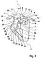
- Fig. 1 shows in a perspective view an example of a device according to the invention produced by a stamping and bending process from a sheet metal strip.
- the embodiment according to Fig. 1 has a head part 1 and a foot part 2 arranged opposite the head part 1.
- the foot part 2 has a rectangular flat rear wall 3, on the longitudinal sides in each of which the head part 1 facing earth region in each case a side wing 4, 5 is formed.
- Each side wing 4, 5 is approximately at right angles to the rear wall 3 in the respective same direction and has in its head part 1 facing area a fixing tongue 6, which extends from the rear wall 3 pointing away obliquely outwards.
- edge webs 7, 8 are formed, each having a curved, extending from the side wings 4, 5 outwardly extending appendage section 9 with the side wings 4, 5 are connected.
- Each edge web 7, 8 has a plane associated with the respective An exertgeabrisk 9 plan cover portion 10 which extends over the length of the side wings 4, 5 and at its outer ends via a respective sloping in the direction of the foot part 2 inclined portion 11 in an approximately square support portion 12 is formed.
- the support sections 12 lie in a plane which is arranged between the fixing tongues 6 and the edge parts of the side wings 4, 5 facing the head part 1.
- the foot part 2 On the side facing away from the head part 1 short edge side of the rear wall 3, the foot part 2 has a bent over bending portion 13 which extends from this short edge side of the rear wall 3 away in the direction of the head part 1 on the side of the rear wall 3, on which the side wings. 4 , 5 are arranged.
- At the bent portion 13 is at the end facing away from the rear wall 3 end with a short edge side a rectangular shaped front wall 14 attached as part of a front wall assembly, which is aligned obliquely from the Umbiegeabêt 13 to the rear wall 3 and extending from this pioneering in the direction of the head part 1 ,
- At the long edge sides of the front wall 14 are in this embodiment as functional parts of a manipulation structure and as physical parts of the front wall assembly locking wings 15, 16 attached, which are aligned approximately at right angles to the front wall 14 and extending from the rear wall 3 pointing away to the outside.
- Each blocking wing 15, 16 is formed with a Aufgleitschräge 17 leading the way from the bending section 13 and with a latching step 18 on the side facing the head part 1.
- Each latching step 18 has an aligned approximately parallel to the front wall 14 and at a distance from this aligned bearing side 19 and an approximately perpendicular to the front wall 14 aligned rear handle side 20, which adjoins the Aufgleitschräge 17 at its end facing away from the front wall 14 ,
- a rectangular guide tongue 21 is attached to the short edge side of the front wall 14 opposite the folding section 13 as a further part of the manipulation structure, which is inclined relative to the front wall 14 and extends in the direction of the rear wall 3.
- the remote from the front wall 14 free end of the guide tongue 21 terminates approximately in the plane of from the bending portion 13 facing away from the edge sides of the rear wall 3 and the side wings 4, 5th
- Fig. 1 It can be seen that the parts of the manipulation structure, namely in the embodiment according to Fig. 1 the blocking vanes 15, 16 and the guide tongue 21, lie in a tool channel 22 which is arranged between the front wall 14 adjacent arranged support portions 12 of the edge webs 7, 8.
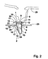
- Fig. 2 shows the embodiment according to Fig. 1 in a longitudinal section in a predetermined arrangement, in which the foot part 2 has been inserted into an inserted in a support member 23 insertion recess 24 while sliding the Aufgleitschrägen 17 at the edge of the insertion recess 24 and compression of the front wall 14 in the direction of the rear wall 3 during the insertion process, while the support portions 12 rest on a to be connected to the support member 23 attachment 25, here in the form of a so-called "retainer" when attaching an airbag device also called “airbag” and thereby connect the attachment 25 with the support member 23.
- a so-called "retainer” when attaching an airbag device also called “airbag” and thereby connect the attachment 25 with the support member 23.
- the front wall 14 is opposite to in FIG Fig. 1
- the contact sides 19 of the blocking wings 15, 16 abut against the edge of the insertion recess 24, while the rearward sides 20 of the blocking wings 15, 16 adjoin the insertion recess 24 and the attachment part 25 facing away from the edge region of the support member 23 engage behind and the rear wall 3 rests against the edge of the insertion recess 24.
- the device according to the invention is anchored in the insertion recess 24 with a very high pull-out force, so that the attachment 25 is connected very stably to the carrier part 23.
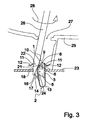
- FIG. 3 shows in one of the illustration according to Fig. 2 corresponding sectional view of the arrangement according to Fig. 2 with a partially illustrated screwdriver
- the screwdriver blade 26 has been inserted as a tool for releasing the connection between the device according to the invention and the support member 23 through a trained in the attachment 25 through-hole 27 into the tool channel 22.
- the screwdriver blade 26 is guided by the inclined guide tongue 21 in the direction of the side facing away from the rear wall 3 side of the front wall 14 between the locking wings 15, 16 and between the front wall 14 and the edge of the insertion recess 24.
- the front wall 14 is opposite to the arrangement according to FIG Fig.
- Fig. 4 shows in a representation according to Fig. 2 and Fig. 3 the embodiment according to Fig. 1 after turning the screwdriver blade 26 in the direction of rotation 28 to one of the arrangement according to Fig. 3 in approximately rectangular orientation, in the due to the width of the screwdriver blade 26 in the region of the tool channel 22, the front wall 14 with respect to the arrangement according to Fig. 3 is further offset in the direction of the rear wall 3 and the rear grip of the rear grip sides 20 with the adjoining the insertion recess 24 edge portion of the support member 23 is completely dissolved.
- the device according to the invention can now be removed again without hindrance from the insertion recess 24 and thus remove the attachment 25 from the carrier part 23.
- the fixing tongues 6 secure the device according to the invention against unintentional falling off of the attachment 25.
Landscapes
- Engineering & Computer Science (AREA)
- General Engineering & Computer Science (AREA)
- Mechanical Engineering (AREA)
- Connection Of Plates (AREA)
- Toys (AREA)
- Helmets And Other Head Coverings (AREA)
- Supports Or Holders For Household Use (AREA)
- Steps, Ramps, And Handrails (AREA)
Abstract
Description
Die Erfindung betrifft eine Vorrichtung zum Befestigen eines Anbauteiles an einem Trägerteil gemäß dem Oberbegriff des Patentanspruches 1.The invention relates to a device for attaching an attachment to a support member according to the preamble of
Eine derartige Vorrichtung ist aus
Eine weitere Vorrichtung zum Befestigen eines Anbauteiles an einem Trägerteil ist aus
Der Erfindung liegt die Aufgabe zugrunde, eine Vorrichtung zum Befestigen eines Anbauteiles an einem Trägerteil der eingangs genannten Art anzugeben, die sich bei einem sicheren Halt in einer in einem Trägerteil eingebrachten Einfügeausnehmung wieder verhältnismäßig einfach entfernen lässt.The invention has for its object to provide a device for attaching an attachment to a support member of the type mentioned above, which can be relatively easily removed with a secure hold in an inserted in a support member insertion recess.
Diese Aufgabe wird bei einer Vorrichtung zum Befestigen eines Anbauteiles an einem Trägerteil der eingangs genannten Art erfindungsgemäß mit den kennzeichnenden Merkmalen des Patentanspruches 1 gelöst.This object is achieved according to the invention in a device for attaching an attachment to a support member of the type mentioned above with the characterizing features of
Dadurch, dass die erfindungsgemäße Vorrichtung einen Werkzeugkanal aufweist, der beispielsweise mit einem Werkzeug einen Zugriff auf die Vorderwand zulässt, und dass an der Vorderwand eine Manipulationsstruktur ausgebildet ist, die im Zusammenwirken mit einem baubedingt mit Sicherheit zwischen die Vorderwand und den Rand der Einfügeausnehmung einführbaren Werkzeug ein Bewegen der Vorderwand in Richtung der Rückwand und damit ein Lösen des Hintergriffs zulässt, lässt sich ohne Beeinträchtigung der Festigkeit der ursprünglich hergestellten Verbindung die erfindungsgemäße Vorrichtung wieder von dem Trägerteil lösen.Characterized in that the device according to the invention comprises a tool channel, the access, for example with a tool allows on the front wall, and in that on the front wall, a manipulation structure is formed, which in cooperation with a building due to the construction with security between the front wall and the edge of the insertion recess insertable tool allows movement of the front wall in the direction of the rear wall, thereby releasing the rear handle allows Without loosing the strength of the originally produced compound, the device according to the invention can be released again from the carrier part.
Weitere zweckmäßige Ausgestaltungen der Erfindung sind Gegenstand der Unteransprüche.Further expedient embodiments of the invention are the subject of the dependent claims.
Aus der nachfolgenden Beschreibung eines bevorzugten Ausführungsbeispiels der Erfindung unter Bezug auf die Figuren der Zeichnung ergeben sich weitere zweckmäßige Ausgestaltungen und Vorteile. Es zeigen:
- Fig. 1
- in einer perspektivischen Ansicht ein Ausführungsbeispiel einer mit einer Manipulationsstruktur ausgebildeten erfindungsgemäßen Vorrichtung,
- Fig. 2
- im Schnitt das Ausführungsbeispiel gemäß
Fig. 1 in einer Einbausituation, - Fig. 3
- im Schnitt die Anordnung des erfindungsgemäßen Ausführungsbeispieles gemäß
Fig. 2 mit einem Werkzeug in Eingriff mit der Manipulationsstruktur und - Fig. 4
- im Schnitt das Ausführungsbeispiel gemäß
Fig. 1 nach Entfernen aus der Anordnung gemäßFig. 2 undFig. 3 .
- Fig. 1
- 3 is a perspective view of an exemplary embodiment of a device according to the invention formed with a manipulation structure,
- Fig. 2
- in section, the embodiment according to
Fig. 1 in a mounting situation, - Fig. 3
- in section, the arrangement of the embodiment according to the invention
Fig. 2 with a tool in engagement with the manipulation structure and - Fig. 4
- in section, the embodiment according to
Fig. 1 after removal from the assembly according toFig. 2 andFig. 3 ,
Das Fußteil 2 weist eine rechteckförmige flache Rückwand 3 auf, an deren Längsseiten in deren jeweiligen dem Kopfteil 1 zugewandten Erdbereich jeweils ein Seitenflügel 4, 5 angeformt ist. Jeder Seitenflügel 4, 5 steht in etwa rechtwinklig zu der Rückwand 3 in die jeweils gleiche Richtung ab und weist in seinem dem Kopfteil 1 zugewandten Bereich eine Fixierzunge 6 auf, die sich von der Rückwand 3 wegweisend schräg nach außen ausgestellt erstreckt.The
An den Seitenflügeln 4, 5 sind bündig mit der mit dem Kopfteil 1 abschließenden kurzen Randseite der Rückwand 3 Randstege 7, 8 angeformt, die jeweils über einen gebogenen, sich von den Seitenflügeln 4, 5 weg nach außen erstreckenden Anfügeabschnitt 9 mit den Seitenflügeln 4, 5 verbunden sind. Jeder Randsteg 7, 8 verfügt über einen mit dem jeweiligen Anfügeabschnitt 9 verbundenen planen Deckabschnitt 10, der sich über die Länge der Seitenflügel 4, 5 erstreckt und an dessen äußeren Enden über jeweils einen in Richtung des Fußteiles 2 geneigten Schrägabschnitt 11 ein in etwa quadratischer Auflageabschnitt 12 angeformt ist. Die Auflageabschnitte 12 liegen in einer Ebene, die zwischen den Fixierzungen 6 und den dem Kopfteil 1 zugewandten Randseiten der Seitenflügel 4, 5 angeordnet ist. Dadurch ist eine gewisse Elastizität in Längsrichtung der erfindungsgemäßen Vorrichtung erzielt.On the
An der dem Kopfteil 1 abgewandten kurzen Randseite der Rückwand 3 weist das Fußteil 2 einen rund umgebogenen Umbiegeabschnitt 13 auf, der sich von dieser kurzen Randseite der Rückwand 3 weg in Richtung des Kopfteiles 1 auf die Seite der Rückwand 3 erstreckt, auf der die Seitenflügel 4, 5 angeordnet sind.On the side facing away from the
An den Umbiegeabschnitt 13 ist an dem von der Rückwand 3 abgewandten Ende mit einer kurzen Randseite eine rechteckig ausgebildete Vorderwand 14 als Teil einer Vorderwandanordnung angesetzt, die sich von dem Umbiegeabschnitt 13 schräg zu der Rückwand 3 ausgerichtet und von dieser wegweisend in Richtung des Kopfteiles 1 erstreckt. An den langen Randseiten der Vorderwand 14 sind bei diesem Ausführungsbeispiel als funktionale Teile einer Manipulationsstruktur und als körperliche Teile der Vorderwandanordnung Sperrflügel 15, 16 angesetzt, die in etwa rechtwinklig zu der Vorderwand 14 ausgerichtet sind und sich von der Rückwand 3 wegweisend nach außen erstrecken.At the
Jeder Sperrflügel 15, 16 ist mit einer von dem Umbiegeabschnitt 13 wegweisend ansteigenden Aufgleitschräge 17 und auf der dem Kopfteil 1 zugewandten Seite mit einer Raststufe 18 ausgebildet. Jede Raststufe 18 weist eine in etwa parallel zu der Vorderwand 14 ausgerichtete sowie in einem Abstand von dieser ausgerichtete Anlageseite 19 und eine in etwa rechtwinklig zu der Vorderwand 14 ausgerichtete Hintergriffseite 20 auf, die sich an ihrem der Vorderwand 14 abgewandten Ende an die Aufgleitschräge 17 anschließt.Each blocking
Weiterhin ist an die dem Umbiegeabschnitt 13 gegenüberliegenden kurzen Randseite der Vorderwand 14 als weiteres Teil der Manipulationsstruktur eine rechteckige Führungszunge 21 angesetzt, die gegenüber der Vorderwand 14 schräg gestellt ist und sich in Richtung der Rückwand 3 erstreckt. Das von der Vorderwand 14 abgewandte freie Ende der Führungszunge 21 endet in etwa in der Ebene der von dem Umbiegeabschnitt 13 abgewandten Randseiten der Rückwand 3 sowie der Seitenflügel 4, 5.Furthermore, a
Aus
In dieser Anordnung ist die Vorderwand 14 gegenüber der in
Claims (6)
- Device for fastening an added part (25) to a supporting part (23), having a head portion (1), intended to be supported on the added part (25) or on the supporting part (23), which has sections to be supported (12) which project laterally, and having a foot portion (2) intended for insertion in an opening for insertion (24) formed in the supporting part (23), which foot portion (2) has a rear wall (3) which, when the foot portion (2) is in a position where it is inserted in the opening for insertion (24), is arranged opposite the edge of the opening for insertion (24), and which foot portion (2) is formed to have a front wall arrangement (14) which is connected to the rear wall (3) by a bent-round section (13), which is resilient relative to the rear wall (3), which extends towards the head portion (1) while pointing away from the rear wall (3) and which, when the foot portion (2) is in a position where it is inserted in the opening for insertion (24), engages behind, by its free end adjacent the head portion (1), an edge region of the supporting part (23) which faces away from the head portion (1) and which is situated around the opening for insertion (24), the head portion (1) having a channel (22) for a tool which forms a continuation of the front wall arrangement (14), there being formed on the front wall arrangement (14) a structure for manipulation (15, 16, 21) which comes into engagement with a tool (26) passed through the channel (22) for a tool to allow the front wall arrangement (14) to be moved towards the rear wall (3) in order to release the engagement of the front wall arrangement (14) behind the edge region of the supporting part (23) which borders on the opening for insertion (24), characterised in that the structure for manipulation has a guiding tongue (21) which is connected to the free end of a front wall (14) of the front wall arrangement and two locking wings (15, 16) integrally formed at the sides of the front wall (14) which extends outwards while pointing away from the rear wall (3), and in that each locking wing (15, 16) has a latching step (18) having a face for abutment (19) aligned parallel to the front wall (14) at a distance therefrom and having a face (20) for engagement behind a surface, the faces for abutment (19) resting against the edge of the opening for insertion (24), and the faces (20) for engagement behind a surface resting against the edge region of the supporting part (23) which faces away from the head portion (1), when the foot portion (2) is in a position where it is inserted in the opening for insertion (24).
- Device according to claim 1, characterised in that the head portion (1) has two elongated edge ribs (7, 8) which project outwards laterally.
- Device according to claim 2, characterised in that there is connected to each end of an edge rib (7, 8) an oblique section (11) which is angled down towards the foot portion (2) and at the end of which is integrally formed a section to be supported (12).
- Device according to claim 2 or claim 3, characterised in that each edge rib (7, 8) is connected to a lateral wing (4, 5) which is integrally formed on one edge of the rear wall (3).
- Device according to one of claims 1 to 4, characterised in that the guiding tongue (21) extends into the region of the head portion (1), at an angle towards the rear wall (3).
- Device according to claim 4 or claim 5, characterised in that each lateral wing (4, 5) has a securing tongue (6) which projects outwards laterally.
Applications Claiming Priority (2)
| Application Number | Priority Date | Filing Date | Title |
|---|---|---|---|
| DE102007042484A DE102007042484B3 (en) | 2007-09-06 | 2007-09-06 | Device for fixing an attachment part to a support part comprises a manipulating structure having a guiding tongue placed on the free end of a front wall of a front wall arrangement and outwardly extending barrier wings |
| PCT/EP2008/006493 WO2009033531A1 (en) | 2007-09-06 | 2008-08-07 | Device for securing an add-on to a support |
Publications (2)
| Publication Number | Publication Date |
|---|---|
| EP2193277A1 EP2193277A1 (en) | 2010-06-09 |
| EP2193277B1 true EP2193277B1 (en) | 2011-12-07 |
Family
ID=40092805
Family Applications (1)
| Application Number | Title | Priority Date | Filing Date |
|---|---|---|---|
| EP08801533A Active EP2193277B1 (en) | 2007-09-06 | 2008-08-07 | Device for securing an add-on to a support |
Country Status (5)
| Country | Link |
|---|---|
| US (1) | US8573881B2 (en) |
| EP (1) | EP2193277B1 (en) |
| AT (1) | ATE536482T1 (en) |
| DE (1) | DE102007042484B3 (en) |
| WO (1) | WO2009033531A1 (en) |
Families Citing this family (24)
| Publication number | Priority date | Publication date | Assignee | Title |
|---|---|---|---|---|
| DE102009054861A1 (en) | 2009-12-17 | 2011-06-22 | Hilti Aktiengesellschaft | Fastening device for attachments to mounting rails |
| US8616516B2 (en) | 2010-03-24 | 2013-12-31 | Intertechnique S.A. | Assembling device for cabin interior components |
| EP2372170B1 (en) * | 2010-03-24 | 2012-12-26 | Intertechnique | Assembling device for cabin interior components |
| DE102010027904A1 (en) | 2010-04-19 | 2011-10-20 | Hilti Aktiengesellschaft | Fastening device for attachments to mounting rails |
| DE102010028653A1 (en) | 2010-05-06 | 2011-11-10 | Hilti Aktiengesellschaft | System for attaching an attachment to mounting rails |
| DE102011114030B4 (en) * | 2011-09-08 | 2019-03-28 | Audi Ag | Spring clip |
| US20140000085A1 (en) * | 2012-07-02 | 2014-01-02 | A. Raymond Et Cie | Removal tool and method for photovoltaic fastener |
| US9331629B2 (en) | 2012-07-02 | 2016-05-03 | A. Raymond Et Cie | Photovoltaic frame fastener |
| DE202014001330U1 (en) * | 2014-02-17 | 2014-03-17 | Bjb Gmbh & Co. Kg | Fastener for fixing two components together |
| EP3012465B1 (en) * | 2013-07-15 | 2016-10-26 | BJB GmbH & Co. KG | Attachment device |
| US9562554B2 (en) | 2015-01-16 | 2017-02-07 | A. Raymond Et Cie | Retainer assembly |
| DE102015117007B3 (en) | 2015-10-06 | 2017-03-30 | Bjb Gmbh & Co. Kg | fastener |
| DE202015107015U1 (en) | 2015-12-22 | 2016-01-19 | Bjb Gmbh & Co. Kg | Fastening element for arranging a printed circuit board on a lamp component |
| DE202016101880U1 (en) * | 2016-04-11 | 2016-04-27 | Häfele Berlin Gmbh & Co Kg | Fitting for detachably connecting two furniture parts |
| US10411442B2 (en) * | 2016-05-10 | 2019-09-10 | Siemens Industry, Inc. | Hold-down and bend-away bracket and bracket assembly |
| DE202016008380U1 (en) * | 2016-10-20 | 2018-01-24 | Lisi Automotive Mecano Gmbh | Crab |
| DE102016012955A1 (en) * | 2016-10-29 | 2018-05-03 | Audi Ag | Spring clip |
| FR3059585A1 (en) * | 2016-12-06 | 2018-06-08 | Compagnie Generale Des Etablissements Michelin | MOLD ELEMENT FOR PNEUMATIC MOLD INCLUDING REMOVABLE INSERT |
| US11585358B2 (en) * | 2017-02-28 | 2023-02-21 | 3M Innovative Properties Company | Attachment device and related methods |
| US10519992B2 (en) * | 2017-11-30 | 2019-12-31 | Ford Global Technologies, Llc | Spring clip with a single resilient cantilevered leg |
| USD874913S1 (en) * | 2018-06-19 | 2020-02-11 | Illinois Tool Works Inc. | Nut retainer |
| DE202018106037U1 (en) * | 2018-10-22 | 2018-11-05 | Igus Gmbh | Channel clip for guide channels of cable drag chains |
| EP3670938A1 (en) | 2018-12-21 | 2020-06-24 | A. Raymond et Cie | Toolless slot fastener |
| US11420571B1 (en) * | 2021-02-25 | 2022-08-23 | A. Raymond Et Cie | Serviceable edge clip assembly |
Family Cites Families (25)
| Publication number | Priority date | Publication date | Assignee | Title |
|---|---|---|---|---|
| US2188026A (en) * | 1935-11-02 | 1940-01-23 | William R Wiley | Clip |
| US2178719A (en) * | 1937-08-23 | 1939-11-07 | Gen Motors Corp | Fastening device |
| GB744172A (en) * | 1953-01-21 | 1956-02-01 | Carr Fastener Co Ltd | Improvements in and relating to fastening devices |
| JPS57101115A (en) * | 1980-12-12 | 1982-06-23 | Nifco Inc | Fastening equipment made of synthetic resin |
| JPS585202U (en) * | 1981-07-01 | 1983-01-13 | 株式会社ニフコ | Mounting structure of vehicle lamp housing |
| JPS58133608U (en) * | 1982-03-04 | 1983-09-08 | 株式会社ニフコ | Latch for joining plates |
| US4683622A (en) * | 1986-03-06 | 1987-08-04 | Eaton Corporation | Releasable fastener |
| JPH0353041Y2 (en) * | 1987-08-31 | 1991-11-19 | ||
| DE4026922C2 (en) * | 1990-08-25 | 1994-11-03 | Raymond A Fa | Retaining clip for fastening components to carrier plates |
| US5036567A (en) * | 1990-12-20 | 1991-08-06 | Eaton Corporation | Push-in fastener clip |
| US5347690A (en) * | 1992-12-15 | 1994-09-20 | Ford Motor Company | Fastener apparatus for an automotive body panel component |
| DE4437630C1 (en) * | 1994-10-21 | 1996-01-25 | Raymond A Gmbh & Co Kg | Kitchen top sink fixing bracket |
| DE19607786C2 (en) * | 1996-03-01 | 2002-11-21 | Harman Audio Electronic Sys | connecting element |
| US5987714A (en) * | 1996-10-07 | 1999-11-23 | Smith; Edward John | Spring fastener of high sealing performance |
| US7168138B2 (en) * | 2000-03-27 | 2007-01-30 | Newfrey Llc | Resilient clip fastener |
| US7784159B2 (en) * | 2002-06-07 | 2010-08-31 | Termax Corporation | Fastener with ergonomic removal to insertion force ratio |
| US6474921B1 (en) * | 2001-07-17 | 2002-11-05 | Trw Inc. | Two part twist fastener |
| US6745440B2 (en) * | 2001-07-31 | 2004-06-08 | Eustathios Vassiliou Revocable Trust | Increased holding power spring fasteners |
| DE10208505B4 (en) * | 2002-02-27 | 2004-07-15 | Decoma (Germany) Gmbh | Connecting element, arrangement of trim part with connecting element and sealing profile and method for assembly |
| EP1507981A1 (en) * | 2002-05-28 | 2005-02-23 | Newfrey LLC | Resilient clip fastener and method of manufacturing the same |
| DE10245276A1 (en) * | 2002-09-27 | 2004-04-01 | A. Raymond & Cie | fastener |
| US6994504B2 (en) * | 2003-06-24 | 2006-02-07 | Trw Automotive U.S. | Two part slide fastener |
| US7351001B1 (en) * | 2003-07-17 | 2008-04-01 | Yazaki North America, Inc. | Pillar shield for securing a wire harness |
| US20060099051A1 (en) * | 2004-11-05 | 2006-05-11 | Moerke Benjamin H | Sealing fastener |
| US7676893B2 (en) * | 2005-04-07 | 2010-03-16 | Newfrey Llc | Silencer plating for fasteners |
-
2007
- 2007-09-06 DE DE102007042484A patent/DE102007042484B3/en not_active Expired - Fee Related
-
2008
- 2008-08-07 US US12/673,329 patent/US8573881B2/en active Active
- 2008-08-07 AT AT08801533T patent/ATE536482T1/en active
- 2008-08-07 WO PCT/EP2008/006493 patent/WO2009033531A1/en active Application Filing
- 2008-08-07 EP EP08801533A patent/EP2193277B1/en active Active
Also Published As
| Publication number | Publication date |
|---|---|
| DE102007042484B3 (en) | 2009-01-08 |
| ATE536482T1 (en) | 2011-12-15 |
| US8573881B2 (en) | 2013-11-05 |
| WO2009033531A1 (en) | 2009-03-19 |
| US20110097137A1 (en) | 2011-04-28 |
| EP2193277A1 (en) | 2010-06-09 |
Similar Documents
| Publication | Publication Date | Title |
|---|---|---|
| EP2193277B1 (en) | Device for securing an add-on to a support | |
| EP2013493B1 (en) | Fastening device | |
| EP2614203B1 (en) | Cable deflector for a cable window regulator | |
| EP2670988B1 (en) | Fastening device | |
| EP1996822B1 (en) | Fixing device | |
| EP1810896A2 (en) | Bracket for a rain sensor | |
| EP2217815B1 (en) | Device for fastening a connector piece to a carrier piece and fastening arrangement having such a device | |
| WO2005060331A2 (en) | Device for connecting a carrier part and an add-on piece | |
| EP2201255A1 (en) | Device for attaching two add-on parts to a carrier part | |
| DE19714459C2 (en) | Connector with a housing lock | |
| EP1963689B1 (en) | Sheet metal nut | |
| WO2005059380A1 (en) | Device for connecting a support element to an add-on piece | |
| DE102006019256B4 (en) | fastening device | |
| EP2198170B1 (en) | Device for fixing an attachment to a supporting part | |
| EP2012390A2 (en) | Ground clamp for potential equalisation of cable conduits | |
| DE3302752C3 (en) | ||
| DE102009033938B4 (en) | Roof window and method for fixing a cover plate | |
| DE10226119A1 (en) | Clamp made of resilient sheet metal | |
| EP2281122B1 (en) | Fastening clamp and arrangement comprising a fastening clamp and an attachment part | |
| EP1800048B1 (en) | Device for joining pipe ends | |
| DE19846668C2 (en) | Safety device for a drainage channel | |
| WO2007042095A1 (en) | Holder for a rod | |
| BE1028531B1 (en) | Fastening device, method, arrangement and control cabinet | |
| DE102020120766A1 (en) | Fastening device, method, arrangement and control cabinet | |
| EP1459938A1 (en) | Fastener for releasably attaching a member to a carrier |
Legal Events
| Date | Code | Title | Description |
|---|---|---|---|
| PUAI | Public reference made under article 153(3) epc to a published international application that has entered the european phase |
Free format text: ORIGINAL CODE: 0009012 |
|
| 17P | Request for examination filed |
Effective date: 20100406 |
|
| AK | Designated contracting states |
Kind code of ref document: A1 Designated state(s): AT BE BG CH CY CZ DE DK EE ES FI FR GB GR HR HU IE IS IT LI LT LU LV MC MT NL NO PL PT RO SE SI SK TR |
|
| AX | Request for extension of the european patent |
Extension state: AL BA MK RS |
|
| DAX | Request for extension of the european patent (deleted) | ||
| GRAP | Despatch of communication of intention to grant a patent |
Free format text: ORIGINAL CODE: EPIDOSNIGR1 |
|
| GRAS | Grant fee paid |
Free format text: ORIGINAL CODE: EPIDOSNIGR3 |
|
| GRAA | (expected) grant |
Free format text: ORIGINAL CODE: 0009210 |
|
| AK | Designated contracting states |
Kind code of ref document: B1 Designated state(s): AT BE BG CH CY CZ DE DK EE ES FI FR GB GR HR HU IE IS IT LI LT LU LV MC MT NL NO PL PT RO SE SI SK TR |
|
| REG | Reference to a national code |
Ref country code: GB Ref legal event code: FG4D Free format text: NOT ENGLISH |
|
| REG | Reference to a national code |
Ref country code: CH Ref legal event code: EP |
|
| REG | Reference to a national code |
Ref country code: IE Ref legal event code: FG4D Free format text: LANGUAGE OF EP DOCUMENT: GERMAN |
|
| REG | Reference to a national code |
Ref country code: DE Ref legal event code: R096 Ref document number: 502008005803 Country of ref document: DE Effective date: 20120209 |
|
| REG | Reference to a national code |
Ref country code: NL Ref legal event code: VDEP Effective date: 20111207 |
|
| PG25 | Lapsed in a contracting state [announced via postgrant information from national office to epo] |
Ref country code: LT Free format text: LAPSE BECAUSE OF FAILURE TO SUBMIT A TRANSLATION OF THE DESCRIPTION OR TO PAY THE FEE WITHIN THE PRESCRIBED TIME-LIMIT Effective date: 20111207 Ref country code: NO Free format text: LAPSE BECAUSE OF FAILURE TO SUBMIT A TRANSLATION OF THE DESCRIPTION OR TO PAY THE FEE WITHIN THE PRESCRIBED TIME-LIMIT Effective date: 20120307 |
|
| LTIE | Lt: invalidation of european patent or patent extension |
Effective date: 20111207 |
|
| PG25 | Lapsed in a contracting state [announced via postgrant information from national office to epo] |
Ref country code: LV Free format text: LAPSE BECAUSE OF FAILURE TO SUBMIT A TRANSLATION OF THE DESCRIPTION OR TO PAY THE FEE WITHIN THE PRESCRIBED TIME-LIMIT Effective date: 20111207 Ref country code: SI Free format text: LAPSE BECAUSE OF FAILURE TO SUBMIT A TRANSLATION OF THE DESCRIPTION OR TO PAY THE FEE WITHIN THE PRESCRIBED TIME-LIMIT Effective date: 20111207 Ref country code: HR Free format text: LAPSE BECAUSE OF FAILURE TO SUBMIT A TRANSLATION OF THE DESCRIPTION OR TO PAY THE FEE WITHIN THE PRESCRIBED TIME-LIMIT Effective date: 20111207 Ref country code: SE Free format text: LAPSE BECAUSE OF FAILURE TO SUBMIT A TRANSLATION OF THE DESCRIPTION OR TO PAY THE FEE WITHIN THE PRESCRIBED TIME-LIMIT Effective date: 20111207 Ref country code: NL Free format text: LAPSE BECAUSE OF FAILURE TO SUBMIT A TRANSLATION OF THE DESCRIPTION OR TO PAY THE FEE WITHIN THE PRESCRIBED TIME-LIMIT Effective date: 20111207 Ref country code: GR Free format text: LAPSE BECAUSE OF FAILURE TO SUBMIT A TRANSLATION OF THE DESCRIPTION OR TO PAY THE FEE WITHIN THE PRESCRIBED TIME-LIMIT Effective date: 20120308 |
|
| PG25 | Lapsed in a contracting state [announced via postgrant information from national office to epo] |
Ref country code: CY Free format text: LAPSE BECAUSE OF FAILURE TO SUBMIT A TRANSLATION OF THE DESCRIPTION OR TO PAY THE FEE WITHIN THE PRESCRIBED TIME-LIMIT Effective date: 20111207 |
|
| REG | Reference to a national code |
Ref country code: IE Ref legal event code: FD4D |
|
| PG25 | Lapsed in a contracting state [announced via postgrant information from national office to epo] |
Ref country code: IS Free format text: LAPSE BECAUSE OF FAILURE TO SUBMIT A TRANSLATION OF THE DESCRIPTION OR TO PAY THE FEE WITHIN THE PRESCRIBED TIME-LIMIT Effective date: 20120407 Ref country code: CZ Free format text: LAPSE BECAUSE OF FAILURE TO SUBMIT A TRANSLATION OF THE DESCRIPTION OR TO PAY THE FEE WITHIN THE PRESCRIBED TIME-LIMIT Effective date: 20111207 Ref country code: BG Free format text: LAPSE BECAUSE OF FAILURE TO SUBMIT A TRANSLATION OF THE DESCRIPTION OR TO PAY THE FEE WITHIN THE PRESCRIBED TIME-LIMIT Effective date: 20120307 Ref country code: SK Free format text: LAPSE BECAUSE OF FAILURE TO SUBMIT A TRANSLATION OF THE DESCRIPTION OR TO PAY THE FEE WITHIN THE PRESCRIBED TIME-LIMIT Effective date: 20111207 Ref country code: EE Free format text: LAPSE BECAUSE OF FAILURE TO SUBMIT A TRANSLATION OF THE DESCRIPTION OR TO PAY THE FEE WITHIN THE PRESCRIBED TIME-LIMIT Effective date: 20111207 Ref country code: IE Free format text: LAPSE BECAUSE OF FAILURE TO SUBMIT A TRANSLATION OF THE DESCRIPTION OR TO PAY THE FEE WITHIN THE PRESCRIBED TIME-LIMIT Effective date: 20111207 |
|
| PG25 | Lapsed in a contracting state [announced via postgrant information from national office to epo] |
Ref country code: RO Free format text: LAPSE BECAUSE OF FAILURE TO SUBMIT A TRANSLATION OF THE DESCRIPTION OR TO PAY THE FEE WITHIN THE PRESCRIBED TIME-LIMIT Effective date: 20111207 Ref country code: PT Free format text: LAPSE BECAUSE OF FAILURE TO SUBMIT A TRANSLATION OF THE DESCRIPTION OR TO PAY THE FEE WITHIN THE PRESCRIBED TIME-LIMIT Effective date: 20120409 Ref country code: PL Free format text: LAPSE BECAUSE OF FAILURE TO SUBMIT A TRANSLATION OF THE DESCRIPTION OR TO PAY THE FEE WITHIN THE PRESCRIBED TIME-LIMIT Effective date: 20111207 |
|
| PLBE | No opposition filed within time limit |
Free format text: ORIGINAL CODE: 0009261 |
|
| STAA | Information on the status of an ep patent application or granted ep patent |
Free format text: STATUS: NO OPPOSITION FILED WITHIN TIME LIMIT |
|
| PG25 | Lapsed in a contracting state [announced via postgrant information from national office to epo] |
Ref country code: DK Free format text: LAPSE BECAUSE OF FAILURE TO SUBMIT A TRANSLATION OF THE DESCRIPTION OR TO PAY THE FEE WITHIN THE PRESCRIBED TIME-LIMIT Effective date: 20111207 |
|
| 26N | No opposition filed |
Effective date: 20120910 |
|
| PG25 | Lapsed in a contracting state [announced via postgrant information from national office to epo] |
Ref country code: IT Free format text: LAPSE BECAUSE OF FAILURE TO SUBMIT A TRANSLATION OF THE DESCRIPTION OR TO PAY THE FEE WITHIN THE PRESCRIBED TIME-LIMIT Effective date: 20111207 |
|
| REG | Reference to a national code |
Ref country code: DE Ref legal event code: R097 Ref document number: 502008005803 Country of ref document: DE Effective date: 20120910 |
|
| BERE | Be: lapsed |
Owner name: A. RAYMOND ET CIE Effective date: 20120831 |
|
| REG | Reference to a national code |
Ref country code: CH Ref legal event code: PL |
|
| PG25 | Lapsed in a contracting state [announced via postgrant information from national office to epo] |
Ref country code: MC Free format text: LAPSE BECAUSE OF NON-PAYMENT OF DUE FEES Effective date: 20120831 |
|
| GBPC | Gb: european patent ceased through non-payment of renewal fee |
Effective date: 20120807 |
|
| PG25 | Lapsed in a contracting state [announced via postgrant information from national office to epo] |
Ref country code: ES Free format text: LAPSE BECAUSE OF FAILURE TO SUBMIT A TRANSLATION OF THE DESCRIPTION OR TO PAY THE FEE WITHIN THE PRESCRIBED TIME-LIMIT Effective date: 20120318 Ref country code: CH Free format text: LAPSE BECAUSE OF NON-PAYMENT OF DUE FEES Effective date: 20120831 Ref country code: LI Free format text: LAPSE BECAUSE OF NON-PAYMENT OF DUE FEES Effective date: 20120831 |
|
| PG25 | Lapsed in a contracting state [announced via postgrant information from national office to epo] |
Ref country code: BE Free format text: LAPSE BECAUSE OF NON-PAYMENT OF DUE FEES Effective date: 20120831 |
|
| PG25 | Lapsed in a contracting state [announced via postgrant information from national office to epo] |
Ref country code: FI Free format text: LAPSE BECAUSE OF FAILURE TO SUBMIT A TRANSLATION OF THE DESCRIPTION OR TO PAY THE FEE WITHIN THE PRESCRIBED TIME-LIMIT Effective date: 20111207 |
|
| PG25 | Lapsed in a contracting state [announced via postgrant information from national office to epo] |
Ref country code: GB Free format text: LAPSE BECAUSE OF NON-PAYMENT OF DUE FEES Effective date: 20120807 |
|
| PG25 | Lapsed in a contracting state [announced via postgrant information from national office to epo] |
Ref country code: MT Free format text: LAPSE BECAUSE OF FAILURE TO SUBMIT A TRANSLATION OF THE DESCRIPTION OR TO PAY THE FEE WITHIN THE PRESCRIBED TIME-LIMIT Effective date: 20111207 |
|
| PG25 | Lapsed in a contracting state [announced via postgrant information from national office to epo] |
Ref country code: TR Free format text: LAPSE BECAUSE OF FAILURE TO SUBMIT A TRANSLATION OF THE DESCRIPTION OR TO PAY THE FEE WITHIN THE PRESCRIBED TIME-LIMIT Effective date: 20111207 |
|
| PG25 | Lapsed in a contracting state [announced via postgrant information from national office to epo] |
Ref country code: LU Free format text: LAPSE BECAUSE OF NON-PAYMENT OF DUE FEES Effective date: 20120807 |
|
| REG | Reference to a national code |
Ref country code: DE Ref legal event code: R082 Ref document number: 502008005803 Country of ref document: DE |
|
| PG25 | Lapsed in a contracting state [announced via postgrant information from national office to epo] |
Ref country code: HU Free format text: LAPSE BECAUSE OF FAILURE TO SUBMIT A TRANSLATION OF THE DESCRIPTION OR TO PAY THE FEE WITHIN THE PRESCRIBED TIME-LIMIT Effective date: 20080807 |
|
| REG | Reference to a national code |
Ref country code: AT Ref legal event code: MM01 Ref document number: 536482 Country of ref document: AT Kind code of ref document: T Effective date: 20130807 |
|
| PG25 | Lapsed in a contracting state [announced via postgrant information from national office to epo] |
Ref country code: AT Free format text: LAPSE BECAUSE OF NON-PAYMENT OF DUE FEES Effective date: 20130807 |
|
| REG | Reference to a national code |
Ref country code: FR Ref legal event code: PLFP Year of fee payment: 9 |
|
| REG | Reference to a national code |
Ref country code: FR Ref legal event code: PLFP Year of fee payment: 10 |
|
| REG | Reference to a national code |
Ref country code: FR Ref legal event code: PLFP Year of fee payment: 11 |
|
| P01 | Opt-out of the competence of the unified patent court (upc) registered |
Effective date: 20230524 |
|
| PGFP | Annual fee paid to national office [announced via postgrant information from national office to epo] |
Ref country code: FR Payment date: 20230824 Year of fee payment: 16 Ref country code: DE Payment date: 20230821 Year of fee payment: 16 |