EP2192385A1 - Signalverarbeitungsmodul, Navigationsvorrichtung mit dem Signalverarbeitungsmodul, Fahrzeug, das mit einer Navigationsvorrichtung versehen ist, und Verfahren zum Bereitstellen von Navigationsdaten - Google Patents
Signalverarbeitungsmodul, Navigationsvorrichtung mit dem Signalverarbeitungsmodul, Fahrzeug, das mit einer Navigationsvorrichtung versehen ist, und Verfahren zum Bereitstellen von Navigationsdaten Download PDFInfo
- Publication number
- EP2192385A1 EP2192385A1 EP08170000A EP08170000A EP2192385A1 EP 2192385 A1 EP2192385 A1 EP 2192385A1 EP 08170000 A EP08170000 A EP 08170000A EP 08170000 A EP08170000 A EP 08170000A EP 2192385 A1 EP2192385 A1 EP 2192385A1
- Authority
- EP
- European Patent Office
- Prior art keywords
- signal
- acceleration measurement
- difference
- acceleration
- facility
- Prior art date
- Legal status (The legal status is an assumption and is not a legal conclusion. Google has not performed a legal analysis and makes no representation as to the accuracy of the status listed.)
- Withdrawn
Links
- 238000012545 processing Methods 0.000 title claims abstract description 26
- 238000000034 method Methods 0.000 title claims description 18
- 230000001133 acceleration Effects 0.000 claims abstract description 136
- 238000005259 measurement Methods 0.000 claims abstract description 84
- 239000013598 vector Substances 0.000 claims abstract description 76
- 239000011159 matrix material Substances 0.000 claims abstract description 57
- 238000004364 calculation method Methods 0.000 claims abstract description 14
- 230000010354 integration Effects 0.000 claims description 21
- 238000005070 sampling Methods 0.000 claims description 12
- 230000003111 delayed effect Effects 0.000 claims description 6
- 230000007274 generation of a signal involved in cell-cell signaling Effects 0.000 claims description 6
- 230000007246 mechanism Effects 0.000 claims description 6
- 230000000694 effects Effects 0.000 description 6
- 238000004088 simulation Methods 0.000 description 4
- 230000008901 benefit Effects 0.000 description 2
- 230000008569 process Effects 0.000 description 2
- 238000012937 correction Methods 0.000 description 1
- 230000001934 delay Effects 0.000 description 1
- 230000001419 dependent effect Effects 0.000 description 1
- 238000009795 derivation Methods 0.000 description 1
- 238000011156 evaluation Methods 0.000 description 1
- 230000014509 gene expression Effects 0.000 description 1
- 230000006872 improvement Effects 0.000 description 1
- 239000000463 material Substances 0.000 description 1
- 230000003287 optical effect Effects 0.000 description 1
- 239000000779 smoke Substances 0.000 description 1
- 230000003595 spectral effect Effects 0.000 description 1
- 230000009897 systematic effect Effects 0.000 description 1
Images


Classifications
-
- G—PHYSICS
- G01—MEASURING; TESTING
- G01C—MEASURING DISTANCES, LEVELS OR BEARINGS; SURVEYING; NAVIGATION; GYROSCOPIC INSTRUMENTS; PHOTOGRAMMETRY OR VIDEOGRAMMETRY
- G01C25/00—Manufacturing, calibrating, cleaning, or repairing instruments or devices referred to in the other groups of this subclass
- G01C25/005—Manufacturing, calibrating, cleaning, or repairing instruments or devices referred to in the other groups of this subclass initial alignment, calibration or starting-up of inertial devices
Definitions
- the present invention relates to a signal processing module.
- the present invention further relates to a navigation device provided with a signal processing module.
- the present invention further relates to a vehicle provided with a navigation device.
- the present invention further relates to a method of providing navigation data.
- Inertial sensors comprise gyroscopes and accelerometers. Gyroscopes provide information about the orientation of the vehicle and accelerometers provide information about its acceleration. If the initial position and velocity of a vehicle are known, its momentaneous velocity and position can be estimated by numerical integration of the acceleration and orientation data obtained from the accelerometers and gyroscopes.
- accelerometers have a systematic error, also denoted as bias, resulting in a drift in position indication, exponential in time. Accordingly, such navigation systems based on inertial sensors need to be calibrated periodically to measure and compensate the sensor biases. With low-cost sensors, and without bias compensation, the navigation solution becomes useless within minutes.
- a method to calculate a bias and a sensor signal compensated for bias is known as indexing.
- This method involves measuring acceleration at predetermined orientations, e.g. 0 and 180° of the acceleration sensor and calculating the bias from the sum of the measurement results. The estimation of the bias obtained in this way can be used to correct the measurement result.
- This has the disadvantage that the acceleration measurement has to be periodically interrupted for calibration.
- a bias compensated acceleration signal may be obtained by subtraction of the measurement results. This has the disadvantage that it is necessary to wait until the sensor has rotated over 180 degrees before a new bias compensated acceleration signal sample is available.
- US7212944 describes a method for determining bias comprising a plurality of sensors. Sequentially a different sensor is rotated, while the outputs of the other sensors are used to perform inertial calculations continuously through time. As each of the acceleration sensors is rotated from time to time, the effect of bias is averaged out. Although this allows for a continuous measurement of the acceleration, a relatively complex control of the acceleration sensors is required for sequentially rotating one of the sensors and for selecting the other sensors for determining the acceleration signal.
- a signal processing module is provided as claimed in claim 1.
- a navigation device is provided as claimed in claim 2.
- a vehicle as claimed in claim 10 is provided.
- a first and a second acceleration measurement vector signal are provided that respectively comprise a first and a second sequence of vector signal samples.
- the vector signal samples comprise at least a first and a second linearly independent acceleration measurement signal component.
- These signal components are preferably obtained by measurement of the acceleration along mutually orthogonal axes, but alternatively said axes may have a relative orientation of an angle differing from 90°, for example in a range of 20° to 160°.
- An angle of rotation signal is provided that is indicative for the difference in orientation at which the sample of the first sequence and the corresponding sample of the second sequence were obtained.
- At least one difference signal is generated from the first and the second acceleration measurement vector signal, inverted matrix data is provided by inverting a matrix derived from the angle of rotation difference signal and subsequently a bias signal and/or an object state signal corrected for bias is estimated from the at least one difference signal and the inverted matrix data.
- the first and the second acceleration measurement vector signal may be subject to further operations before generation of the difference signal.
- acceleration measurement samples at different orientations are periodically sampled. Taking into account the difference in orientation at which the sample of the first sequence and the corresponding sample of the second sequence were obtained the contribution of bias to the measured signal samples and an estimation for the bias-compensated signal can be periodically obtained.
- the inertial sensor unit comprises a first and a second inertial sensor that provide the first and the second acceleration measurement vector signal respectively, as well as a rotation facility that causes a relative rotation between the first and the second inertial sensor.
- the relative rotation may be generated for example in that each of the inertial sensors is independently rotated by a respective actuator at a mutually different rotational speed. Preferably, however, only one of the sensors is rotated, while the other has a fixed orientation.
- the device has a difference signal generating module that comprises integration and subtraction facilities.
- the difference signal generating module is arranged for determining at least a difference between an n th order integrand of the first and the second acceleration measurement vector signal and a difference between an m th order integrand of the first and the second acceleration measurement vector signal wherein m and n are mutually different integers greater or equal than 0.
- the inverse calculation module comprises integration facilities that derive the matrix from the angle of rotation signal.
- the value for m and n differs by one to minimize the number of integrations.
- the values of m and n are 1 and 2 respectively. This implies that a difference in velocity and a difference in position are estimated from the sensor signals.
- a difference in acceleration and a difference in velocity are estimated from the sensor signals.
- this embodiment is relatively sensitive for the influence of the rotation imposed on the sensor(s). Accordingly a more accurate estimation of bias and the bias compensated acceleration signal is obtained by a selection of the values 1 and 2 for m and n respectively. It is assumed that a higher order integration does not further improve accuracy noticeably.
- a larger plurality of sensors may be used. In that case the bias and/or the bias compensated acceleration signal may be determined with an improved precision.
- the angle of rotation signal indicative for a difference in orientation at which the sample of the first sequence and the corresponding sample of the second sequence were obtained, may be derived in various ways.
- the relative orientation of the acceleration sensors may be measured by optical encoding means.
- the orientation of each of the sensors may be measured by a respective angular sensor, e.g. a gyroscope with integration means or a compass.
- an actuator that imposes a relative rotation upon the sensors may issue a signal indicative for the momentaneous angle between the first and the second inertial sensor.
- the inertial sensor unit comprises a single acceleration sensor for generating a single acceleration measurement vector signal.
- a signal splitting facility derives the first and the second acceleration measurement vector signals from the single acceleration measurement vector signal, for example by alternately assigning a sample of the single acceleration measurement vector signal as a sample of the first and as a sample of the second acceleration measurement vector signal.
- the angle of rotation signal of the orientation signal generation unit is indicative for an orientation of the acceleration sensor.
- the single acceleration sensor may be rotated controllably by an actuator, but may otherwise be passively rotated by movements of a vehicle at which the sensor is mounted or by a combination of both.
- the angle of rotation signal indicative for a difference in orientation at which the sample of the first sequence and the corresponding sample of the second sequence were obtained, may be derived in various ways e.g. by a gyroscope with integration means or a compass mechanically coupled to the single acceleration sensor.
- the navigation device comprises a difference signal generating module with a delay facility for delaying the samples of the first acceleration measurement signal for synchronization with corresponding samples of the second acceleration measurement signal. It further comprises a rotation compensation facility for compensating for a difference in orientation of the acceleration sensor between the moment of sampling a sample for the first acceleration measurement signal vector and the moment of sampling a corresponding second sample for the second acceleration measurement signal vector.
- the compensation facility is controlled by the rotation orientation signal.
- the second embodiment is advantageous in that only a single acceleration sensor is required and in that it is not necessary to actively rotate the single sensor. It is sufficient that naturally occurring rotations, e.g. caused by a vehicle at which the sensor is mounted are present. Signals obtained by a conventional acceleration sensor may be used. This is advantageous in that the invention can be applied to vehicles provided with such a conventional acceleration sensor by processing the acceleration sensor signal with a signal processing module according to the invention. This embodiment is particular suitable if the momentaneous rotation frequency is relatively high in comparison with the bandwidth with which the acceleration sensor is sampled. If the average rotation frequency of naturally occurring rotations is too low the acceleration sensor may still be actively rotated by an additional actuator.
- the navigation device may be used as a standalone device, for a fireman may carry the device to navigate within a building obscured by smoke.
- the invention relates further to a vehicle provided with a navigation device according to the invention.
- the vehicle is for example a bicycle, car, motorcycle, train, ship, boat, or aircraft.
- the vehicle comprises a drive and steering mechanism controlled by the navigation device.
- the vehicle may comprise a further navigation facility such as a GPS receiver, or an odometer, for providing information relating to a state of the vehicle, the state comprising at least one of a position, a velocity and an acceleration and an orientation of the vehicle.
- a combination facility may be present for combining the object-state signal of the navigation device with the information provided by the further navigation facility.
- the combination facility may for example select the most reliable information for navigation.
- signal processing can be implemented in hardware, software, or a combination of both.
- first, second, third etc. may be used herein to describe various elements, components, and/or sections, these elements, components, and/or sections should not be limited by these terms. These terms are only used to distinguish one element, component or section from another element, component, and/or section. Thus, a first element, component, and/or section discussed below could be termed a second element, component, and/or section without departing from the teachings of the present invention.
- Figure 1 schematically shows a navigation device 1 that comprises an inertial sensor unit 10 for providing a first and a second acceleration measurement vector signal S1, S2 and an orientation signal generation unit 20, here embedded in the inertial sensor unit for providing an angle of rotation signal R ⁇ .
- the first and the second acceleration measurement vector signal S1, S2 respectively comprise a first and a second sequence of vector signal samples S1 i , S2 i .
- the vector signal samples S1 i , S2 i comprise at least a first and a second linearly independent acceleration measurement signal component, wherein the vector signal samples represent a measurement result of an acceleration sensor having a variable orientation as a function of time. Samples S1 i in the first sequence have a corresponding sample S2 i in the second sequence.
- the angle of rotation signal R ⁇ is indicative for a difference in orientation at which the sample S1 i of the first sequence and the corresponding sample S2 i of the second sequence were obtained.
- the apparatus shown in Figure 1 has a signal processing module 50 for estimating a bias signal b1, b2 and/or an object state signal p, v, a corrected for bias.
- the signal processing module 50 comprises a difference signal generating module 60 for generating at least one difference signal ⁇ from the first and the second acceleration measurement vector signal S1, S2, and an inverse calculation module 70 with a matrix inversion facility 71 for providing inverted matrix data by inverting a matrix derived from the angle of rotation signal R ⁇ and a matrix multiplication facility 72 for estimating from the at least one difference signal and the inverted matrix data a bias signal b1, b2 and/or an object state signal corrected for bias.
- the signal processing module may comprise a filter facility, e.g. low-pass filter facility to eliminate noise from the output signals from the bias signal and or corrected object state signal.
- the filter facility is preferably applied after the matrix multiplication facility, but alternatively the input signals ( ⁇ , M -1 ) of the matrix multiplication facility may be filtered. Likewise the input signals of the signal processing facility (S1, S2, R ⁇ ) may be filtered for this purpose.
- Figure 2 schematically indicates the relation between signals occurring in a basic inertial measurement system.
- the measured angular velocity ⁇ is numerically integrated yielding the orientation of the vehicle body ⁇ .
- the orientation ⁇ is used to calculate a so-called rotation matrix R be (usually this integration is done such that it yields directly R be ).
- R be so-called rotation matrix
- the acceleration vector a b measured with respect to the vehicle body frame axis (indicated with a subscript b)
- the inertial acceleration vector a e (indicated by a subscript e) is now numerically integrated twice to obtain the velocity v e of the body and the position p e , both with respect to an inertial frame.
- the inertial sensor unit 10 comprises a first and a second inertial sensor 12, 14 that provide the first and the second acceleration measurement vector signal S1, S2 respectively.
- the inertial sensor unit 10 further comprises a rotation facility 16 that causes a relative rotation between the first and the second inertial sensor 12, 14.
- both inertial sensors are coupled, i.e. are both strapped down to the same body, e.g. a navigation device, e.g arranged within a vehicle body.
- a navigation device e.g. arranged within a vehicle body.
- one of the inertial sensors is fixed to the body and the other is rotating with respect to the other.
- both inertial sensors may rotate with respect to the body as long as they rotate relatively to each other.
- the size of both inertial sensors is relatively small and are placed near each other such that they can be assumed to travel equal trajectories. So, both sets of accelerometers travel the same trajectory at all times, and only their orientation differs. This means however that the velocity is also identical at all times.
- the integrand of the second term is known at all times and is derived from the gyro measurements. Integration of the integrand results in a known constant matrix ⁇ (T).
- both the difference in position indication ⁇ p and the difference in velocity reading ⁇ v of both INS-systems associated with the two accelerometers is determined by their biases b 1 and b 2 .
- the relative orientation between the first and the second sensor is actively controlled it can be guaranteed that the two equations [5] are independent. Accordingly, the biases of the two accelerometers can be solved from these set of equations. Knowing the biases b 1 and b 2 , the corrected values for the velocity and position can be obtained.
- R rb ( t ) is a time varying rotation matrix associated with the rotation of the second accelerometer relative to the (also rotating) body frame.
- a r t t is the acceleration measured by the second set of accelerometers in the frame rotating with respect to the body.
- both sets of accelerometers are strapped down to the same navigation device, they have the same acceleration in the frame of the navigation device and mathematical rotation through R be is not necessary. If the mathematical rotation through R be is omitted, the first part of the right side of the above set of equations has no physical meaning anymore, but still the set of equations is mathematically still identical.
- ⁇ p * and ⁇ v * are the difference in position and velocity readings of both INS systems, the "star" indicating that the rotation through R be is omitted.
- I 1 and I 2 represent the single and double integrated identity matrix.
- ⁇ 1 and ⁇ 2 represent the single and double integration of the time varying R rb matrix.
- the signal processing facility 50 for carrying out these calculations is now described in more detail. It should be understood that the facility may be implemented in dedicated hardware, but may alternatively be implemented by a suitably programmed general purpose processor for example, or a combination of both.
- the difference signal generating module 60 comprises integration facilities 61a, 61b, 62a, 62b and subtraction facilities 63, 64.
- the difference signal generating module 60 is arranged for determining at least a difference between an n th order integrand of the first and the second acceleration measurement vector signal and a difference between an m th order integrand of the first and the second acceleration measurement vector signal wherein m and n are mutually different integers greater or equal than 0.
- integration facilities 61a, 62a respectively calculate a velocity vector signal v1, v2 from the sensor signals S1, S2.
- the integration facilities 61b, 62b respectively calculate a position vector signal p1, p2, from the velocity vector signals v1, v2 respectively.
- Subtraction facility 64 calculates a difference ⁇ v between the velocities that were obtained by single integration from the sensor signals S1, S2.
- Subtraction facility 63 calculates a difference ⁇ p between the positions that were obtained by double integration from the sensor signals S1, S2. As indicated by equation [7] both differences ⁇ p, ⁇ v are only dependent on the bias b1, b2 of the sensors 12, 14.
- the inverse calculation module 70 determines the biases b1, b2 of the sensors 12, 14 by inverse calculation.
- the inverse calculation module 70 comprises a matrix integration facility 73a, 73b, for integrating the matrix p representative for the difference in orientation R ⁇ between the sensors 12, 14. Likewise the unity matrix is integrated to obtain its first and second order integrand I 1 and I 2 respectively.
- the matrix M is indicative for a difference in orientation at which the sample of the first sequence S1 and the corresponding sample S2 of the second sequence were obtained.
- the result is inverted into matrix M -1 by matrix inversion unit 71. From the concatenation ⁇ vp of the difference signals ⁇ v, ⁇ p and the inverted matrix M -1 a bias signal b1, b2 and/or an object state signal corrected for bias is calculated.
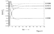
- the embodiment of Figure 3 was simulated. In this simulation a continuous rotation of the second accelerometer 14 was presumed of 1.8 degrees/second. Further more noise of 100 ⁇ g/ ⁇ Hz (achievable for MEMS accelerometers) has been added to the accelerometer output. Additionally, a set of biases in the order of 1 mg was applied to the accelerometer outputs. The bandwidth of the accelerometers was 100 Hz.
- Figure 4 shows the estimated biases as a function of time. As confirmed by the results of the simulations, shown in Figure 4 , the bias can be accurately estimated semi-continuously.
- the parameters n,m used for calculating a difference between an n th order integrand of the first and the second acceleration measurement vector signal and a difference between an m th order integrand of the first and the second acceleration measurement vector signal are 1 and 2 respectively.
- the value of these parameters n,m is not relevant provided that m and n are mutually different integers greater or equal than 0.
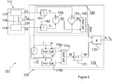
- Figure 5 shows an alternative embodiment, wherein the parameters m and n are 0 and 1 respectively.
- the difference signals used to determine the bias of the acceleration sensors 112, 114 are an acceleration difference signal ⁇ a, indicative for a difference in acceleration measured by the sensors and a velocity difference signal ⁇ v indicative for a difference in velocity estimated by integration of the acceleration signals of each of the sensors 112, 114.
- the bias can be determined it is more important that the two sensors are accurately positioned relative to each other. I.e. the sensors should substantially have the same position in the coordinate system sensed by the sensors. I.e.
- the centre of mass of the sensors should have the same x-y coordinates.
- the sensors may differ in z-position provided that the navigation device is usually not subject to rotations around other axes that the z-axis, for example with application in cars.
- the higher numbers for the parameters m,n may be selected, but it is suspected that this does not lead to further improvement, while it requires more processing steps.
- Figure 6 shows a further embodiment. Parts therein corresponding to those in Figure 3 have a reference number that is 200 higher.
- the difference signal generating module 260 differs from the one shown in Figure 3 in that first a difference signal ⁇ a is calculated from the acceleration measurement signals S1, S2 and that subsequently the first order and the second order integrand ⁇ v, ⁇ p respectively, of this difference signal are obtained.
- These difference signals ⁇ v, ⁇ p are equivalent to the difference signals ⁇ v, ⁇ p obtained by the embodiment of Figure 3 and are used in the same way to estimate the bias b1, b2 of the acceleration sensors 212,214.
- first and second acceleration measurement vector signal S1, S2 are provided by respective acceleration sensors.
- Embodiments having a single acceleration sensor are elucidated below by a theoretical framework followed by practical examples.
- a r i t is the measured acceleration, expressed in the axis reference system co-rotating with the accelerometer.
- the subscript r is used to denote this rotating axis system.
- a b t t is the true acceleration in the body reference system.
- b r is the constant bias on the output of the accelerometers and
- n ( t ) is the measurement noise vector, both expressed in the axis system co-rotating with the accelerometer.
- R br is the rotation matrix associated with the rotation of the accelerometer with respect to the vehicle body. It is used to mathematically rotate the true acceleration in the body reference system to the rotating reference system and vice versa.
- a sampling frequency of at least F s must be used. Obviously, higher sampling frequencies will do too.
- a sampling frequency of 2*F s is used and that the stream of samples is split into a stream of odd numbered samples S1 and a stream of even numbered samples S2, as indicated in Figure 7 .
- a r (t) is the original signal at the filtered output of the accelerometer, sampled at twice the sampling frequency.
- the stream S of samples a r (t) is split by a demultiplexing facility 380 into a sequence S1 of odd numbered samples sampled at T+Ts, T+3Ts, ...
- the effect of such a delay can be compensated by mathematically rotating the signal back over an angle of ⁇ , or in this case equivalently, by rotating forward the non-delayed signal the same amount with rotation element 364.
- the bias on the signals however, is not influenced by physical rotation nor by time delays.
- R ⁇ is a rotation matrix associated with the rotation over ⁇ .
- the rotation matrix R ⁇ is provided by orientation signal generation unit 320.
- This unit 320 comprises an angle of rotation sensor 322 that provides an indication ⁇ (t) for the momentaneous orientation of the sensor 312 at the time t of sampling the acceleration.
- the angle of rotation sensor 322 may comprise a gyroscope and an integrator, but may alternatively be another type of orientation sensor (e.g, a compass that estimates the orientation from the earth magnetic field).
- Subtraction element 326 subtracts a delayed sample ⁇ (t-Ts) of the orientation indication from the sample ⁇ (t). The delayed sample is obtained from delay element 324.
- Subtraction element 326 provides the rotation matrix associated with the rotation over ⁇ .
- This calculation is carried out by inverse calculation module 370.
- the "single sensor" concept has been simulated to verify the expected principle.
- a low-frequent body acceleration is generated. This acceleration contained a sinusoidal component, a band-pass limited random component and a DC-component on both the x- and y-axis of the acceleration.
- a mechanical rotation of the inertial measurement unit IMU with a rotation frequency above the frequency band of the acceleration signal was simulated.
- the IMU further contained a bias component to be estimated and sensor noise with a density that is achievable for low-cost MEMS accelerometers (100 ⁇ g/ ⁇ Hz).
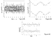
- a time plot of the sensor signals s x , s y (x- and y-values), without the applied acceleration, are given in Figure 9A .
- the sensor signal contains a bias of +/- 0.01 m/s 2 (corresponding to +/- 1 mg) and wideband noise.
- a time plot of the applied body acceleration a x , a y is given in Figure 9B .
- the acceleration contains some sinusoidal component, a DC-component and a low frequent random component.
- the sensor there is no need for the sensor to rotate with respect to the body, e.g. a vehicle. It is sufficient if the body, including the fixed sensor, is rotating. Since the mechanical rotation of the body including sensor is measured by the gyros, the biases may be estimated during periods in time were the body is undergoing relative high frequency rotations in combination with relative low-frequency accelerations. Applications may for instance be in guided munitions.
- Figure 10 shows another embodiment.
- parts corresponding to those in Figure 7 have a reference number that is 100 higher.
- samples from a signal a r (t) obtained with a single sensor 412 are used to estimate a sensor bias and/or an acceleration signal compensated for bias.
- each sample is simultaneously assigned as a sample of the second acceleration measurement vector signal S2, and as a sample of the first acceleration measurement vector signal S1.
- the difference signal generating module 460 determines a difference m(t) between a version of the signal S1delayed by delay element 462 and a non-delayed version of the signals S2, where the signals are corrected for rotation occurring during the delay time by rotation correction element 464.
- This embodiment has the advantage that more efficient use is made of the signal S to determine the bias b.
- the signal S sampled by sample and hold element 486 is provided as the signals S1, S2 to the difference signal generation module 460.
- the signals are sampled synchronously with a clock Cl.
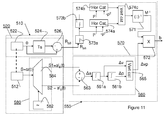
- Figure 11 shows another embodiment of a navigation system comprising a single sensor.
- Parts of the inertial sensor unit 510 and the orientation signal generation unit 520 in this Figure corresponding to those of Figure 5 and 7 have a reference number that is 400 or 200 higher.
- Parts of the signal processing module 550 in Figure 11 corresponding to those of Figure 6 have a reference number that is 300 higher.
- two signals S1, S2 are derived from the same acceleration sensor 512.
- the second signal S2 is delayed relative to the first signal S1 by one clock cycle.
- the signal processing circuit 550 processes these signals S1, S2 in the same way as it processes the signals S1, S2 obtained from different acceleration sensors 212, 214, as is the case in the embodiment of Figure 6 .
- estimation b1, b2 for the acceleration sensor bias.
- An average value of these two estimations may be used as the estimation b for the bias of the sensor 512.
- the sensor 512 is sufficiently rotated during the measurements. This can be realized in that the navigation system as a whole is rotated during use, e.g. caused by movements of a vehicle, or that a separate actuator rotates the sensor 512.
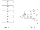
- Figure 12 illustrates a method for providing navigation data.
- a first and a second acceleration measurement vector signal S1, S2 that respectively comprise a first and a second sequence of vector signal samples are provided.
- the vector signal samples comprise at least a first and a second linearly independent acceleration measurement signal component.
- an angle of rotation signal R ⁇ is provided. This signal is indicative for a difference in orientation at which the sample of the first sequence and the corresponding sample of the second sequence were obtained.
- a third step ST3 at least one difference signal m(t) is generated from the first and the second acceleration measurement vector signal S1, S2.
- inverted matrix data is provided by inverting a matrix derived from the angle of rotation signal.
- a bias signal b1, b2 and/or an object state signal corrected for bias is estimated from the at least one difference signal and the inverted matrix data. It is not important in which order steps ST3 and ST4 are carried out.
- Figure 13 shows a possible application of a navigation device according to the invention in a vehicle 2.
- vehicle 2 comprises a navigation device 1 according to one of the previous claims, as well as a drive mechanism 4 and steering mechanism 5 controlled by the navigation device 1, via a control unit 3.
- the control unit 3 uses navigation information retrieved from the navigation device 1 to control a driving speed with which the drive mechanism 4 drives back-wheels 6 and to control an orientation imposed by the steering mechanism 5 on the front wheel 7.
Priority Applications (5)
| Application Number | Priority Date | Filing Date | Title |
|---|---|---|---|
| EP08170000A EP2192385A1 (de) | 2008-11-26 | 2008-11-26 | Signalverarbeitungsmodul, Navigationsvorrichtung mit dem Signalverarbeitungsmodul, Fahrzeug, das mit einer Navigationsvorrichtung versehen ist, und Verfahren zum Bereitstellen von Navigationsdaten |
| US13/130,977 US8768621B2 (en) | 2008-11-26 | 2009-11-26 | Signal processing module, navigation device with the signal processing module, vehicle provided with a navigation device and method of providing navigation data |
| PCT/NL2009/050719 WO2010062176A1 (en) | 2008-11-26 | 2009-11-26 | Signal processing module, navigation device with the signal processing module, vehicle provided with a navigation device and method of providing navigation data |
| CN200980153204.6A CN102272554B (zh) | 2008-11-26 | 2009-11-26 | 信号处理模块、具有信号处理模块的导航设备、设置有导航设备的交通工具和提供导航数据的方法 |
| EP09764917.2A EP2361369B1 (de) | 2008-11-26 | 2009-11-26 | Signalverarbeitungsmodul, navigationsvorrichtung mit dem signalverarbeitungsmodul, fahrzeug, das mit einer navigationsvorrichtung versehen ist, und verfahren zum bereitstellen von navigationsdaten |
Applications Claiming Priority (1)
| Application Number | Priority Date | Filing Date | Title |
|---|---|---|---|
| EP08170000A EP2192385A1 (de) | 2008-11-26 | 2008-11-26 | Signalverarbeitungsmodul, Navigationsvorrichtung mit dem Signalverarbeitungsmodul, Fahrzeug, das mit einer Navigationsvorrichtung versehen ist, und Verfahren zum Bereitstellen von Navigationsdaten |
Publications (1)
| Publication Number | Publication Date |
|---|---|
| EP2192385A1 true EP2192385A1 (de) | 2010-06-02 |
Family
ID=40627585
Family Applications (2)
| Application Number | Title | Priority Date | Filing Date |
|---|---|---|---|
| EP08170000A Withdrawn EP2192385A1 (de) | 2008-11-26 | 2008-11-26 | Signalverarbeitungsmodul, Navigationsvorrichtung mit dem Signalverarbeitungsmodul, Fahrzeug, das mit einer Navigationsvorrichtung versehen ist, und Verfahren zum Bereitstellen von Navigationsdaten |
| EP09764917.2A Not-in-force EP2361369B1 (de) | 2008-11-26 | 2009-11-26 | Signalverarbeitungsmodul, navigationsvorrichtung mit dem signalverarbeitungsmodul, fahrzeug, das mit einer navigationsvorrichtung versehen ist, und verfahren zum bereitstellen von navigationsdaten |
Family Applications After (1)
| Application Number | Title | Priority Date | Filing Date |
|---|---|---|---|
| EP09764917.2A Not-in-force EP2361369B1 (de) | 2008-11-26 | 2009-11-26 | Signalverarbeitungsmodul, navigationsvorrichtung mit dem signalverarbeitungsmodul, fahrzeug, das mit einer navigationsvorrichtung versehen ist, und verfahren zum bereitstellen von navigationsdaten |
Country Status (4)
| Country | Link |
|---|---|
| US (1) | US8768621B2 (de) |
| EP (2) | EP2192385A1 (de) |
| CN (1) | CN102272554B (de) |
| WO (1) | WO2010062176A1 (de) |
Cited By (1)
| Publication number | Priority date | Publication date | Assignee | Title |
|---|---|---|---|---|
| FR3000219A1 (fr) * | 2012-12-26 | 2014-06-27 | Sagem Defense Securite | Procede de comparaison de deux centrales inertielles solidaires d'un meme porteur |
Families Citing this family (10)
| Publication number | Priority date | Publication date | Assignee | Title |
|---|---|---|---|---|
| US9024772B2 (en) * | 2010-09-28 | 2015-05-05 | Xianghui Wang | Multi sensor position and orientation measurement system |
| US8996598B2 (en) * | 2012-06-15 | 2015-03-31 | The Boeing Company | Latency compensation |
| KR20140123258A (ko) * | 2013-04-12 | 2014-10-22 | 삼성전기주식회사 | 3축 가속도 센서의 가속도 측정 회로 |
| US10137972B2 (en) * | 2014-07-28 | 2018-11-27 | Furuno Electric Co., Ltd. | Vessel characteristic estimation device and automatic steering device |
| US9921239B2 (en) * | 2014-11-20 | 2018-03-20 | Stmicroelectronics, Inc. | Offset cancellation device for micro-electromechanical system |
| US9933262B2 (en) | 2015-07-27 | 2018-04-03 | Caterpillar Inc. | Positioning system having a master-slave configuration |
| US11293778B1 (en) * | 2015-11-16 | 2022-04-05 | Tiax Llc | Attitude sensor system with automatic accelerometer bias correction |
| US20190090781A1 (en) * | 2017-09-28 | 2019-03-28 | Vital Connect, Inc. | Sensor calibration considering subject-dependent variables and/or body positions |
| US10983791B2 (en) * | 2018-08-29 | 2021-04-20 | Aktiebolaget Skf | Processor-implemented system and method for vector analysis to extract a speed of a rotating part of a machine where there is no trigger signal present |
| US10539644B1 (en) | 2019-02-27 | 2020-01-21 | Northern Digital Inc. | Tracking an object in an electromagnetic field |
Citations (1)
| Publication number | Priority date | Publication date | Assignee | Title |
|---|---|---|---|---|
| US7066004B1 (en) * | 2004-09-02 | 2006-06-27 | Sandia Corporation | Inertial measurement unit using rotatable MEMS sensors |
Family Cites Families (5)
| Publication number | Priority date | Publication date | Assignee | Title |
|---|---|---|---|---|
| US3509765A (en) * | 1965-12-17 | 1970-05-05 | Gen Motors Corp | Inertial navigation system |
| US5970779A (en) | 1997-09-15 | 1999-10-26 | The United States Of America As Represented By The Secretary Of The Navy | System and method for calibrating accelerometer over low (ocean wave) frequencies |
| WO2002059627A1 (en) | 2000-11-21 | 2002-08-01 | Vega Vista | System and method for calibrating an accelerometer assembly |
| JP4229358B2 (ja) * | 2001-01-22 | 2009-02-25 | 株式会社小松製作所 | 無人車両の走行制御装置 |
| US7103477B1 (en) | 2005-08-08 | 2006-09-05 | Northrop Grumman Corporation | Self-calibration for an inertial instrument based on real time bias estimator |
-
2008
- 2008-11-26 EP EP08170000A patent/EP2192385A1/de not_active Withdrawn
-
2009
- 2009-11-26 EP EP09764917.2A patent/EP2361369B1/de not_active Not-in-force
- 2009-11-26 CN CN200980153204.6A patent/CN102272554B/zh not_active Expired - Fee Related
- 2009-11-26 WO PCT/NL2009/050719 patent/WO2010062176A1/en active Application Filing
- 2009-11-26 US US13/130,977 patent/US8768621B2/en not_active Expired - Fee Related
Patent Citations (2)
| Publication number | Priority date | Publication date | Assignee | Title |
|---|---|---|---|---|
| US7066004B1 (en) * | 2004-09-02 | 2006-06-27 | Sandia Corporation | Inertial measurement unit using rotatable MEMS sensors |
| US7212944B1 (en) | 2004-09-02 | 2007-05-01 | Sandia Corporation | Inertial measurement unit using rotatable MEMS sensors |
Cited By (2)
| Publication number | Priority date | Publication date | Assignee | Title |
|---|---|---|---|---|
| FR3000219A1 (fr) * | 2012-12-26 | 2014-06-27 | Sagem Defense Securite | Procede de comparaison de deux centrales inertielles solidaires d'un meme porteur |
| WO2014102261A1 (fr) * | 2012-12-26 | 2014-07-03 | Sagem Defense Securite | Procede de comparaison de deux centrales inertielles solidaires d'un meme porteur |
Also Published As
| Publication number | Publication date |
|---|---|
| WO2010062176A1 (en) | 2010-06-03 |
| US20110276262A1 (en) | 2011-11-10 |
| US8768621B2 (en) | 2014-07-01 |
| CN102272554B (zh) | 2014-11-12 |
| EP2361369B1 (de) | 2013-07-31 |
| EP2361369A1 (de) | 2011-08-31 |
| CN102272554A (zh) | 2011-12-07 |
Similar Documents
| Publication | Publication Date | Title |
|---|---|---|
| EP2361369B1 (de) | Signalverarbeitungsmodul, navigationsvorrichtung mit dem signalverarbeitungsmodul, fahrzeug, das mit einer navigationsvorrichtung versehen ist, und verfahren zum bereitstellen von navigationsdaten | |
| US11561098B2 (en) | Inertial navigation system | |
| CA2381196C (en) | Vibration compensation for sensors | |
| US7979231B2 (en) | Method and system for estimation of inertial sensor errors in remote inertial measurement unit | |
| CN106969783B (zh) | 一种基于光纤陀螺惯性导航的单轴旋转快速标定技术 | |
| CN107655493B (zh) | 一种光纤陀螺sins六位置系统级标定方法 | |
| EP1983304B1 (de) | Kursstabilisierung für unterstützte Trägheitsnavigationssysteme | |
| EP1896796B1 (de) | Verfahren zum kombinieren von kontinuierlichen und diskontinuierlichen trägheitsinstrumentmessungen und trägheitsnavigationssystem damit | |
| RU2566427C1 (ru) | Способ определения температурных зависимостей масштабных коэффициентов, смещений нуля и матриц ориентации осей чувствительности лазерных гироскопов и маятниковых акселерометров в составе инерциального измерительного блока при стендовых испытаниях | |
| US20160116302A1 (en) | Method for comparing two inertial units integral with a same carrier | |
| Abdel-Hafez | On the development of an inertial navigation error-budget system | |
| RU2300081C1 (ru) | Способ определения инструментальных погрешностей измерителей инерциальной навигационной системы на этапе начальной выставки | |
| Pan et al. | Accurate calibration for drift of fiber optic gyroscope in multi-position north-seeking phase | |
| EP3073226B1 (de) | Kontinuierliche kalibrierung eines inertialen systems | |
| RU2504734C1 (ru) | Способ определения параметров модели погрешностей измерений акселерометров инерциальной навигационной системы по измерениям спутниковой навигации | |
| US9933263B2 (en) | System and method for long baseline accelerometer/GNSS navigation | |
| JP2015004593A (ja) | ナビゲーション装置 | |
| Kozlov et al. | Calibration of inertial measurement units on a low-grade turntable with simultaneous estimation of temperature coefficients | |
| Klimkovich et al. | Determination of time delays in measurement channels during SINS calibration in inertial mode | |
| Björkholm et al. | Navigation in vehicle crash test using MEMS-based IMU | |
| RU2779274C1 (ru) | Способ измерения ошибок начальной выставки инерциальной навигационной системы без привязки к внешним ориентирам | |
| Ailneni et al. | Characterization of MEMS based inertial measurement unit | |
| Prokhortsov et al. | A Method for Calibration of Medium-Accuracy Strapdown INS | |
| CN109631895B (zh) | 一种物体的位姿估计方法和装置 | |
| RU2273858C1 (ru) | Трехкомпонентный измеритель угловой скорости |
Legal Events
| Date | Code | Title | Description |
|---|---|---|---|
| PUAI | Public reference made under article 153(3) epc to a published international application that has entered the european phase |
Free format text: ORIGINAL CODE: 0009012 |
|
| AK | Designated contracting states |
Kind code of ref document: A1 Designated state(s): AT BE BG CH CY CZ DE DK EE ES FI FR GB GR HR HU IE IS IT LI LT LU LV MC MT NL NO PL PT RO SE SI SK TR |
|
| AX | Request for extension of the european patent |
Extension state: AL BA MK RS |
|
| AKY | No designation fees paid | ||
| REG | Reference to a national code |
Ref country code: DE Ref legal event code: 8566 |
|
| STAA | Information on the status of an ep patent application or granted ep patent |
Free format text: STATUS: THE APPLICATION IS DEEMED TO BE WITHDRAWN |
|
| 18D | Application deemed to be withdrawn |
Effective date: 20101203 |