EP2192308A2 - Method and controller for controlling pressure fluid supply for a hydraulic actuator - Google Patents
Method and controller for controlling pressure fluid supply for a hydraulic actuator Download PDFInfo
- Publication number
- EP2192308A2 EP2192308A2 EP09014790A EP09014790A EP2192308A2 EP 2192308 A2 EP2192308 A2 EP 2192308A2 EP 09014790 A EP09014790 A EP 09014790A EP 09014790 A EP09014790 A EP 09014790A EP 2192308 A2 EP2192308 A2 EP 2192308A2
- Authority
- EP
- European Patent Office
- Prior art keywords
- pressure
- speed
- control
- signal
- coefficient
- Prior art date
- Legal status (The legal status is an assumption and is not a legal conclusion. Google has not performed a legal analysis and makes no representation as to the accuracy of the status listed.)
- Granted
Links
- 238000000034 method Methods 0.000 title claims abstract description 16
- 239000012530 fluid Substances 0.000 title abstract description 5
- 238000006073 displacement reaction Methods 0.000 claims abstract description 29
- 230000001276 controlling effect Effects 0.000 claims description 8
- 230000001105 regulatory effect Effects 0.000 claims description 6
- 239000007788 liquid Substances 0.000 claims description 4
- 230000004044 response Effects 0.000 claims description 4
- 230000007423 decrease Effects 0.000 claims description 3
- 230000006978 adaptation Effects 0.000 claims description 2
- 230000003321 amplification Effects 0.000 abstract 1
- 238000003199 nucleic acid amplification method Methods 0.000 abstract 1
- 238000004519 manufacturing process Methods 0.000 description 7
- 238000013016 damping Methods 0.000 description 5
- 230000008859 change Effects 0.000 description 4
- 230000008569 process Effects 0.000 description 4
- 238000007726 management method Methods 0.000 description 3
- 230000006399 behavior Effects 0.000 description 2
- 230000033228 biological regulation Effects 0.000 description 2
- 230000006870 function Effects 0.000 description 2
- 238000001746 injection moulding Methods 0.000 description 2
- 239000000243 solution Substances 0.000 description 2
- 230000001052 transient effect Effects 0.000 description 2
- 230000005540 biological transmission Effects 0.000 description 1
- 238000004364 calculation method Methods 0.000 description 1
- 238000002485 combustion reaction Methods 0.000 description 1
- 230000006835 compression Effects 0.000 description 1
- 238000007906 compression Methods 0.000 description 1
- 238000001816 cooling Methods 0.000 description 1
- 125000004122 cyclic group Chemical group 0.000 description 1
- 238000001514 detection method Methods 0.000 description 1
- 230000006866 deterioration Effects 0.000 description 1
- 238000005461 lubrication Methods 0.000 description 1
- 238000005457 optimization Methods 0.000 description 1
- 230000009467 reduction Effects 0.000 description 1
- 238000003860 storage Methods 0.000 description 1
Images

Classifications
-
- F—MECHANICAL ENGINEERING; LIGHTING; HEATING; WEAPONS; BLASTING
- F15—FLUID-PRESSURE ACTUATORS; HYDRAULICS OR PNEUMATICS IN GENERAL
- F15B—SYSTEMS ACTING BY MEANS OF FLUIDS IN GENERAL; FLUID-PRESSURE ACTUATORS, e.g. SERVOMOTORS; DETAILS OF FLUID-PRESSURE SYSTEMS, NOT OTHERWISE PROVIDED FOR
- F15B11/00—Servomotor systems without provision for follow-up action; Circuits therefor
- F15B11/02—Systems essentially incorporating special features for controlling the speed or actuating force of an output member
-
- F—MECHANICAL ENGINEERING; LIGHTING; HEATING; WEAPONS; BLASTING
- F15—FLUID-PRESSURE ACTUATORS; HYDRAULICS OR PNEUMATICS IN GENERAL
- F15B—SYSTEMS ACTING BY MEANS OF FLUIDS IN GENERAL; FLUID-PRESSURE ACTUATORS, e.g. SERVOMOTORS; DETAILS OF FLUID-PRESSURE SYSTEMS, NOT OTHERWISE PROVIDED FOR
- F15B9/00—Servomotors with follow-up action, e.g. obtained by feed-back control, i.e. in which the position of the actuated member conforms with that of the controlling member
- F15B9/02—Servomotors with follow-up action, e.g. obtained by feed-back control, i.e. in which the position of the actuated member conforms with that of the controlling member with servomotors of the reciprocatable or oscillatable type
- F15B9/04—Servomotors with follow-up action, e.g. obtained by feed-back control, i.e. in which the position of the actuated member conforms with that of the controlling member with servomotors of the reciprocatable or oscillatable type controlled by varying the output of a pump with variable capacity
-
- F—MECHANICAL ENGINEERING; LIGHTING; HEATING; WEAPONS; BLASTING
- F15—FLUID-PRESSURE ACTUATORS; HYDRAULICS OR PNEUMATICS IN GENERAL
- F15B—SYSTEMS ACTING BY MEANS OF FLUIDS IN GENERAL; FLUID-PRESSURE ACTUATORS, e.g. SERVOMOTORS; DETAILS OF FLUID-PRESSURE SYSTEMS, NOT OTHERWISE PROVIDED FOR
- F15B2211/00—Circuits for servomotor systems
- F15B2211/20—Fluid pressure source, e.g. accumulator or variable axial piston pump
- F15B2211/205—Systems with pumps
- F15B2211/20507—Type of prime mover
- F15B2211/20515—Electric motor
-
- F—MECHANICAL ENGINEERING; LIGHTING; HEATING; WEAPONS; BLASTING
- F15—FLUID-PRESSURE ACTUATORS; HYDRAULICS OR PNEUMATICS IN GENERAL
- F15B—SYSTEMS ACTING BY MEANS OF FLUIDS IN GENERAL; FLUID-PRESSURE ACTUATORS, e.g. SERVOMOTORS; DETAILS OF FLUID-PRESSURE SYSTEMS, NOT OTHERWISE PROVIDED FOR
- F15B2211/00—Circuits for servomotor systems
- F15B2211/20—Fluid pressure source, e.g. accumulator or variable axial piston pump
- F15B2211/205—Systems with pumps
- F15B2211/2053—Type of pump
- F15B2211/20546—Type of pump variable capacity
-
- F—MECHANICAL ENGINEERING; LIGHTING; HEATING; WEAPONS; BLASTING
- F15—FLUID-PRESSURE ACTUATORS; HYDRAULICS OR PNEUMATICS IN GENERAL
- F15B—SYSTEMS ACTING BY MEANS OF FLUIDS IN GENERAL; FLUID-PRESSURE ACTUATORS, e.g. SERVOMOTORS; DETAILS OF FLUID-PRESSURE SYSTEMS, NOT OTHERWISE PROVIDED FOR
- F15B2211/00—Circuits for servomotor systems
- F15B2211/60—Circuit components or control therefor
- F15B2211/63—Electronic controllers
- F15B2211/6303—Electronic controllers using input signals
- F15B2211/6306—Electronic controllers using input signals representing a pressure
- F15B2211/6309—Electronic controllers using input signals representing a pressure the pressure being a pressure source supply pressure
-
- F—MECHANICAL ENGINEERING; LIGHTING; HEATING; WEAPONS; BLASTING
- F15—FLUID-PRESSURE ACTUATORS; HYDRAULICS OR PNEUMATICS IN GENERAL
- F15B—SYSTEMS ACTING BY MEANS OF FLUIDS IN GENERAL; FLUID-PRESSURE ACTUATORS, e.g. SERVOMOTORS; DETAILS OF FLUID-PRESSURE SYSTEMS, NOT OTHERWISE PROVIDED FOR
- F15B2211/00—Circuits for servomotor systems
- F15B2211/60—Circuit components or control therefor
- F15B2211/63—Electronic controllers
- F15B2211/6303—Electronic controllers using input signals
- F15B2211/6333—Electronic controllers using input signals representing a state of the pressure source, e.g. swash plate angle
-
- F—MECHANICAL ENGINEERING; LIGHTING; HEATING; WEAPONS; BLASTING
- F15—FLUID-PRESSURE ACTUATORS; HYDRAULICS OR PNEUMATICS IN GENERAL
- F15B—SYSTEMS ACTING BY MEANS OF FLUIDS IN GENERAL; FLUID-PRESSURE ACTUATORS, e.g. SERVOMOTORS; DETAILS OF FLUID-PRESSURE SYSTEMS, NOT OTHERWISE PROVIDED FOR
- F15B2211/00—Circuits for servomotor systems
- F15B2211/60—Circuit components or control therefor
- F15B2211/665—Methods of control using electronic components
- F15B2211/6656—Closed loop control, i.e. control using feedback
Definitions
- the invention relates to a method and a control device for controlling a pressure medium supply for a hydraulic actuator.
- an electric motor drives a pump, which supplies the cylinder with a hydraulic pressure medium according to a pressure / volume flow control.
- a pump which supplies the cylinder with a hydraulic pressure medium according to a pressure / volume flow control.
- a method for controlling a pressure medium supply for a hydraulic actuator of a -z.B. cyclic working - machine provided.
- the actuator is supplied by a variable displacement pump with a pressure medium quantity, wherein the variable displacement pump in turn by a speed-controlled motor -. an electric motor - is driven.
- a signal indicative of the pressure of the pressure medium quantity is fed back to a regulator for driving the variable displacement pump.
- the controller has a comparator and a control amplifier. Parallel to this pressure control circuit, the motor is driven by a speed signal.
- a speed profile for adjusting the speed of the electric motor can be created within a work cycle of the machine to form the speed signal, as is the case EP 1 236 558 B1 describes.
- the electric motor is operated according to the determined speed profile. But it can also be a speed signal from a higher-level control loop or an external control can be specified.
- the properties of the regulator amplifier of the pressure regulator are varied according to the speed signal.
- the control quality of the controller can be left constant at different speeds. As a result, the deterioration of the control quality can be counteracted at reduced speed. Without the corresponding variation of the characteristics of the control amplifiers, the loop gain would also decrease at reduced speed. This may increase a permanent control deviation, or the damping of the control loop will be worse, causing disturbances that affect the control loop, more noticeable. By varying the characteristics of the control amplifier this is counteracted.
- the gain of the variable gain amplifier is adjusted as a function of the rotational speed. With a change in the gain of the control amplifier and the loop gain is changed, whereby this can be kept substantially constant even at different speeds.
- the gain of the variable gain amplifier is increased to leave the loop gain substantially constant.
- disturbances at low speed do not lead to a much larger control deviation than at high speed.
- the pressure regulator has a differentiating element with a coefficient KD for differentiating the signal, which indicates the pressure of the pressure medium quantity.
- the coefficient KD of the differentiating element is set as a function of the rotational speed.
- the coefficient of the differentiator is set to higher values to counteract a drop in damping at low speeds.
- the method is particularly suitable in a plastic processing machine in which liquid plastic is injected into a mold.
- Other applications may be presses, in particular press brakes. In such machines, the same operations are often repeated so that the pressure medium requirement is the same for each working cycle.
- the invention also relates to a control device for controlling a pressure medium supply for a hydraulic actuator of a - eg cyclically operating - machine.
- the actuator of one of a speed-controlled motor - for example, an electric motor, possibly, for example, an internal combustion engine, a diesel engine, a gasoline engine - powered variable displacement pump supplied with a pressure medium.
- the pressure regulator for driving the variable displacement pump and a pressure transducer for converting the pressure of the pressure medium quantity into a feedback signal for the pressure regulator are provided.
- the control device may also include a device for establishing a speed profile for adjusting the speed of the motor during a cycle of the machine and an adjuster for operating the motor according to the determined speed profile in the working cycles of the machine.
- the speed of the motor can also be controlled and adjusted by means of a control device supplied speed signal.
- the control device includes a control adjustment device for adjusting the characteristics of the pressure regulator in accordance with the speed signal. The control device thus makes it possible to leave the control quality substantially constant over a large speed range.
- the pressure regulator comprises a comparator and a variable gain control amplifier, wherein the gain of the variable gain amplifier is adjusted in response to the speed signal. This adjusts the loop gain and thus also the control deviation. Preferably, the gain of the control amplifier is increased when reducing the speed.
- the pressure regulator has a differentiating element with a coefficient KD for differentiating that signal which indicates the pressure of the pressure medium quantity.
- the control adjusting device is set to adjust the coefficient of the differentiating element in response to the rotational speed signal.
- the coefficient KD of the differentiator is set to higher values.
- the invention also relates to an assembly of a control device according to the invention and an actuator whose supply is provided with a hydraulic pressure by means of the control device.
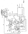
- FIG. 1 shows an actuator of a production machine and the control used to provide hydraulic pressure means for this actuator.
- Actuator 11 is a cylinder for a cyclical manufacturing machine that injects liquid plastic into a mold.
- a duty cycle is divided into several consecutive sections of the cycle, which differ in terms of the required amount of pressure. Each of these sections is a work process. Operations include, for example, "close tool”, “inject plastic”, “open the tool”, “wait for a hold phase”, or the like.
- variable displacement pump 13 conveys pressure medium into the line 16 from a tank 15, whereupon the hydraulic fluid in the line 16 has a pressure p.
- the valve 17 is provided between the conduit 16 and the actuator 11. This valve 17 controls the volume flow from the variable displacement pump 13 to the cylinder 11 and from there back to the tank 15.
- the valve 17 is electrically controlled by a higher-level control 25 with the signal u1, which is conducted via the line 27.
- a Wegemessumformer 21 measures the position of the piston rod of the cylinder 11, converts this position into an electrical signal s1, which is output via the line 23 to the higher-level controller 25.
- a control device which includes the means for controlling the pressure medium supply 10, the pressure transducer 40, the actuator 31, the transmitter 32, the frequency converter 33, the electric motor 14, the shaft 34 and the variable displacement pump 13 contains.
- the device 10 receives from the higher-level controller 25 a setpoint for the pressure ps and a setpoint for the volume flow Qs.
- the setpoints ps and Qs correspond to a pressure volumetric flow profile P (t) / Q (t) stored in the higher-level controller.
- the device 10 receives a cycle start signal yt0 indicating when a new cycle begins.
- the device 10 receives the signal pi from the pressure transducer 40, which converts the pressure p in the line 16 into a corresponding electrical signal pi.
- the device 10 outputs a desired value for the rotational speed ns and an output signal for the delivery volume yVF.
- the signal ns receives the frequency converter 33, which accordingly drives the electric motor 14 at a frequency f such that the rotational speed n of the electric motor 14 is equal to the target value for the rotational speed ns.
- the rotational movement of the electric motor is transmitted via the shaft 34 to the variable displacement pump 13.
- the speed n of the electric motor 14 is not measured and fed back, the speed n is thus controlled in the open circuit.
- the actuator 31 receives the output signal yVF from the device 10 and controls the delivery volume VF of the variable displacement pump 13.
- the transducer 32 outputs an electrical signal indicative of the actual value of the delivery volume VFi of the variable displacement pump 13.
- the device 10 includes a pump controller 41, a motor controller 42, a multiplier 44, and a calculator 45.
- the multiplier 44 is implemented as a proportional element with a controllable gain KQ.
- the arithmetic unit 45 receives as an input signal the setpoint value for the speed ns and outputs its reciprocal value to its output as the signal KQ.
- the multiplier receives at its inputs the setpoint for the volume flow QS and the signal KQ.
- the multiplier 44 thus forms from the desired value QS for the volume flow to be supplied to the cylinder, taking into account the rotational speed n of the electric motor 14, a target value VFs for the delivery volume of the variable displacement pump 13.
- the pump regulator 41 receives as input the actual value for the delivery volume VFi, the actual Value for the pressure pi, the setpoint for the delivery volume VFs and the setpoint for the pressure ps and outputs at its output the output signal for the delivery volume yVF.
- FIG. 2 shows details of the pump controller 41 FIG. 1 ,
- the pressure regulator 41 has a first summation element 48, a second summation element 51, a delivery volume regulator 49, a pressure regulator 52 and a minimum value selection element 50.
- the first summation element 48 forms from the desired value VFs and the actual value VFi a control difference, which is supplied to the delivery volume controller 49 as an input signal.
- the output signal of the delivery volume controller 49 is added to the minimum value selection element 50 as the first input signal.
- the second summation element 51 receives the desired value for the pressure ps and the actual value for the pressure pi, from which the control difference for the pressure is formed by subtraction and output to the pressure regulator 52.
- the pressure regulator 52 outputs as an output the value yp to the minimum value selector 50 which receives the value yp at its second input.
- the minimum value selector element 50 selects the smaller of the two input signals yVF1 and yp and forwards this minimum value as manipulated variable yVF for the delivery volume VF to the actuator 31. Both the regulation of the delivery volume VF and the regulation of the pressure p takes place with the aid of adjusting the delivery volume of the variable displacement pump 13.
- the transmission characteristics of the delivery flow regulator 49 and the pressure regulator 52 each have a proportional and a differential component.
- a pressure / volume flow profile p (t) / Q (t) for the pressure medium supply of the cylinder 11 is stored.
- a speed profile n (t) for the electric motor is as in the document EP 1 236 558 B1 created.
- a speed profile n (t) is created for the electric motor 14, which specifies the course of the rotational speed n during a production cycle.
- the electric motor 14 is first operated at the constant speed nmax.
- the control of the cylinder 11 supplied volume flow is carried out solely by the pump controller 41.
- the pump controller 41 ensures that the variable displacement pump 13 to the cylinder 11, the volume flow which is required to the by the pressure / flow profile p (t) / Q (t) specified values. This volume flow is also referred to below as the volume flow requirement QA.
- nmax the highest speed with which the electric motor 14 is to be operated in the production cycles. This speed is usually the rated speed of the electric motor 14th
- the optimization process has a series of learning cycles in which the variable displacement pump 13 is driven at the constant speed nmax.
- a first learning cycle the duration of a manufacturing cycle is determined by measuring the time between two cycle start pulses. From the duration of a production cycle and the number of memory locations available in the motor controller 42 for storing values, the time interval ⁇ t for the detection of the values to be stored is determined.
- the actual values VFi of the delivery volume are detected at a distance of ⁇ t and stored in the engine control unit 42. The values stored there form a delivery volume profile VFI (t).
- the actual values pi of the pressure are detected and stored in the engine controller 42.
- the stored values form a pressure profile pi (t).
- a volume flow demand profile QA (t) is obtained.
- a speed profile n (t) is obtained. It is advisable to choose the constant value so that it is close to the nominal value of the delivery volume VF of the variable displacement pump 13.
- the constant value is chosen such that it corresponds to approximately 90% of the nominal value of the delivery volume VF of the variable displacement pump 13. This value is denoted below by VFgO.
- the stored value of the volume flow demand QA can be replaced by the speed value n calculated from it. If one controls the speed of the electric motor 14 in accordance with the speed profile n (t) determined in this way, the delivery volume VF of the variable displacement pump 13 would adjust to the value VFgO under ideal conditions. In practice, however, the delivery volume VF of the variable displacement pump 13 is not constant during a cycle, in particular because the speed n of the electric motor 14 can not be changed as fast as the delivery volume VF of the variable displacement pump 13. In addition, in particular with regard to the lubrication of Variable 13, the cooling of the electric motor 14 and the maximum torque of the electric motor 14 its speed n may not be arbitrarily reduced.
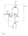
- FIG. 3 shows details of the pressure regulator 52 in a schematic overview.
- the pressure regulator 52 includes a differentiating member 521, a proportional member 522, a summing member 524, and an adjusting block 523.
- the proportional member 522 receives the control difference for the pressure from the second summing member 51 of the pressure regulator 41. This control difference is multiplied by the coefficient Kp and the result of this Multiplication to a first input of the summation 524 out.
- the differentiator 521 receives the actual value for the pressure pi, which is derived in the differentiator 521 and multiplied by the factor KD, which is the coefficient of the differentiator 521.
- the result of this multiplication is fed to the second input of the summation element 524.
- the summer 524 subtracts the value at its second input from the value at its first input and outputs the result of this difference as the output yp.
- the adjustment block 523 receives at its input the setpoint for the speed ns and outputs at its outputs values with which the coefficients Kp and KD are varied.
- a value table is stored in the adjustment block 523, which indicates how large the factors Kp and KD are in the different value ranges of the setpoint speed ns. For example, in a speed range of 600 to 800 rpm, the factor Kp is set twice as large as in the speed range of 1300 to 1500 rpm. Accordingly, the factor KD is increased in the low speed range in comparison to the high speed range.
Landscapes
- Engineering & Computer Science (AREA)
- Physics & Mathematics (AREA)
- Fluid Mechanics (AREA)
- Mechanical Engineering (AREA)
- General Engineering & Computer Science (AREA)
- Fluid-Pressure Circuits (AREA)
Abstract
Description
Die Erfindung betrifft ein Verfahren und eine Regelungsvorrichtung zur Regelung einer Druckmittelzufuhr für einen hydraulischen Aktor. Bei Kunststoffspritzgießmaschinen mit einem hydraulisch betriebenen Zylinder treibt ein Elektromotor eine Pumpe an, die dem Zylinder ein hydraulisches Druckmittel gemäß einer Druck/Volumenstrom-Regelung zuführt. In dem Arbeitszyklus der Kunststoffspritzgießmaschine gibt es Bereiche, in denen der Druck geregelt wird, sowie weitere Bereiche, in denen der Volumenstrom geregelt wird.The invention relates to a method and a control device for controlling a pressure medium supply for a hydraulic actuator. In plastic injection molding machines with a hydraulically operated cylinder, an electric motor drives a pump, which supplies the cylinder with a hydraulic pressure medium according to a pressure / volume flow control. In the work cycle of the plastic injection molding machine, there are areas in which the pressure is controlled, as well as other areas in which the flow rate is controlled.
In der
Es ist Aufgabe der Erfindung, ein Verfahren sowie eine Regelvorrichtung zur Regelung einer Druckmittelzufuhr für einen hydraulischen Aktor bereitzustellen, wobei die Regelgüte im Vergleich zu bekannten Lösungen verbessert wird.It is an object of the invention to provide a method and a control device for controlling a pressure medium supply for a hydraulic actuator, wherein the control quality is improved compared to known solutions.
Diese Aufgabe wird durch den Gegenstand der unabhängigen Patentansprüche gelöst. Vorteilhafte Ausgestaltungen ergeben sich aus den Unteransprüchen.This object is solved by the subject matter of the independent patent claims. Advantageous embodiments emerge from the subclaims.
Erfindungsgemäß wird ein Verfahren zur Regelung einer Druckmittelzufuhr für einen hydraulischen Aktor einer -z.B. zyklisch arbeitenden - Maschine bereitgestellt. Der Aktor wird von einer Verstellpumpe mit einer Druckmittelmenge versorgt, wobei die Verstellpumpe ihrerseits von einem drehzahlgesteuerten Motor - z.B. ein Elektromotor - angetrieben ist.According to the invention, a method for controlling a pressure medium supply for a hydraulic actuator of a -z.B. cyclic working - machine provided. The actuator is supplied by a variable displacement pump with a pressure medium quantity, wherein the variable displacement pump in turn by a speed-controlled motor -. an electric motor - is driven.
Ein Signal, das den Druck der Druckmittelmenge anzeigt, wird zu einem Regler zum Ansteuern der Verstellpumpe rückgekoppelt. Der Regler weist einen Vergleicher sowie einen Regelverstärker auf. Parallel zu diesem Druckregelkreis wird der Motor anhand eines Drehzahlsignals angesteuert. Es kann z.B. ein Drehzahl-Profil zum Einstellen der Drehzahl des Elektromotors innerhalb eines Arbeitszyklus der Maschine erstellt werden, um das Drehzahlsignal zu bilden, wie es an sich die
Durch die Variation der Eigenschaften des Regelverstärkers kann die Regelgüte des Reglers bei unterschiedlichen Drehzahlen konstant gelassen werden. Dadurch kann dem Verschlechtern der Regelgüte bei erniedrigter Drehzahl entgegen gewirkt werden. Ohne die entsprechende Variation der Eigenschaften der Regelverstärker würde sich bei verringerter Drehzahl auch die Kreisverstärkung verringern. Damit vergrößert sich unter Umständen eine bleibende Regelabweichung, oder die Dämpfung des Regelkreises wird schlechter, wodurch sich Störungen, die auf den Regelkreis einwirken, stärker bemerkbar machen. Durch die Variation der Eigenschaften des Regelverstärkers wird dem entgegengewirkt.By varying the characteristics of the control amplifier, the control quality of the controller can be left constant at different speeds. As a result, the deterioration of the control quality can be counteracted at reduced speed. Without the corresponding variation of the characteristics of the control amplifiers, the loop gain would also decrease at reduced speed. This may increase a permanent control deviation, or the damping of the control loop will be worse, causing disturbances that affect the control loop, more noticeable. By varying the characteristics of the control amplifier this is counteracted.
In einer Ausführungsform wird die Verstärkung des Regelverstärkers in Abhängigkeit der Drehzahl eingestellt. Mit einer Veränderung der Verstärkung des Regelverstärkers wird auch die Kreisverstärkung verändert, wodurch diese auch bei unterschiedlichen Drehzahlen im Wesentlich konstant gehalten werden kann.In one embodiment, the gain of the variable gain amplifier is adjusted as a function of the rotational speed. With a change in the gain of the control amplifier and the loop gain is changed, whereby this can be kept substantially constant even at different speeds.
Vorzugsweise wird bei der Verringerung der Drehzahl die Verstärkung des Regelverstärkers erhöht, um die Kreisverstärkung im Wesentlichen konstant zu lassen. Damit führen Störungen bei niedriger Drehzahl nicht zu einer wesentlich größeren Regelabweichung als bei hoher Drehzahl.Preferably, as the speed is reduced, the gain of the variable gain amplifier is increased to leave the loop gain substantially constant. Thus disturbances at low speed do not lead to a much larger control deviation than at high speed.
In einer weiteren Ausführungsform weist der Druckregler ein Differenzierglied mit einem Beiwert KD zum Differenzieren des Signals, das den Druck der Druckmittelmenge anzeigt, auf. Dabei wird der Beiwert KD des Differenzierglieds in Abhängigkeit von der Drehzahl eingestellt. Hiermit kann auch das dynamische Verhalten des Druckreglers über den gesamten Drehzahlbereich im Wesentlichen stabil gehalten werden. Somit dauern Einschwingvorgänge auch bei unterschiedlich eingestellten Drehzahlen ähnlich lang. Es wird insbesondere eine bei allen Drehzahlen gleiche, im Wesentlichen konstante Dämpfung erreicht. Einschwingvorgänge haben damit immer die gleiche Charakteristik und Dauer.In a further embodiment, the pressure regulator has a differentiating element with a coefficient KD for differentiating the signal, which indicates the pressure of the pressure medium quantity. In this case, the coefficient KD of the differentiating element is set as a function of the rotational speed. Hereby, the dynamic behavior of the pressure regulator over the entire speed range can be kept substantially stable. Thus, transient processes take a similar length even at different speeds set. In particular, a substantially constant damping at all speeds is achieved. Transient processes always have the same characteristics and duration.
Bevorzugt wird dabei, dass bei verringerter Drehzahl der Beiwert des Differenzierglieds auf höhere Werte eingestellt wird, um einem Abfall der Dämpfung bei niedrigen Drehzahlen entgegen zu wirken. Besonders geeignet ist das Verfahren bei einer Kunststoffverarbeitungsmaschine, bei der flüssiger Kunststoff in eine Form eingespritzt wird. Weitere Anwendungen können Pressen, insbesondere Abkantpressen sein. Bei solchen Maschinen werden die gleichen Arbeitsschritte oft wiederholt, so dass der Druckmittelbedarf bei jedem Arbeitszyklus gleich verläuft.It is preferred that at reduced speed, the coefficient of the differentiator is set to higher values to counteract a drop in damping at low speeds. The method is particularly suitable in a plastic processing machine in which liquid plastic is injected into a mold. Other applications may be presses, in particular press brakes. In such machines, the same operations are often repeated so that the pressure medium requirement is the same for each working cycle.
Die Erfindung betrifft auch eine Regelvorrichtung zur Regelung einer Druckmittelzufuhr für einen hydraulischen Aktor einer - z.B. zyklisch arbeitenden - Maschine. Bei dieser Maschine wird der Aktor von einer von einem drehzahlgesteuerten Motor - z.B. ein Elektromotor, ggf. z.B. auch ein Verbrennungsmotor, ein Dieselmotor, ein Ottomotor.- angetriebenen Verstellpumpe mit einer Druckmittelmenge versorgt. Der Druckregler zum Ansteuern der Verstellpumpe und ein Druckumformer zum Umsetzen des Drucks der Druckmittelmenge in ein Rückkopplungssignal für den Druckregler sind vorgesehen. Die Regelvorrichtung weist unter Umständen auch eine Vorrichtung zum Erstellen eines Drehzahl-Profils zum Einstellen der Drehzahl des Motors während eines Zyklus der Maschine und eine Einstellvorrichtung zum Betreiben des Motors entsprechend dem ermittelten Drehzahl-Profil in den Arbeitszyklen der Maschine auf. Die Drehzahl des Motors kann aber auch anhand eines der Regelvorrichtung zugeführten Drehzahlsignals gesteuert und verstellt werden. Die Regelvorrichtung enthält eine Reglungsanpassungsvorrichtung zum Anpassen der Eigenschaften des Druckreglers entsprechend dem Drehzahlsignal. Die Regelvorrichtung ermöglicht somit, die Regelgüte über einen großen Drehzahlbereich im Wesentlichen konstant zu lassen.The invention also relates to a control device for controlling a pressure medium supply for a hydraulic actuator of a - eg cyclically operating - machine. In this machine, the actuator of one of a speed-controlled motor - for example, an electric motor, possibly, for example, an internal combustion engine, a diesel engine, a gasoline engine - powered variable displacement pump supplied with a pressure medium. The pressure regulator for driving the variable displacement pump and a pressure transducer for converting the pressure of the pressure medium quantity into a feedback signal for the pressure regulator are provided. The control device may also include a device for establishing a speed profile for adjusting the speed of the motor during a cycle of the machine and an adjuster for operating the motor according to the determined speed profile in the working cycles of the machine. The speed of the motor can also be controlled and adjusted by means of a control device supplied speed signal. The control device includes a control adjustment device for adjusting the characteristics of the pressure regulator in accordance with the speed signal. The control device thus makes it possible to leave the control quality substantially constant over a large speed range.
In einer Ausführungsform weist der Druckregler einen Vergleicher und einen Regelverstärker mit einem Proportionalglied auf, wobei die Verstärkung des Regelverstärkers in Abhängigkeit von dem Drehzahlsignal eingestellt wird. Damit werden die Kreisverstärkung und somit auch die Regelabweichung eingestellt. Bevorzugt wird dabei bei Verringerung der Drehzahl die Verstärkung des Regelverstärkers erhöht.In one embodiment, the pressure regulator comprises a comparator and a variable gain control amplifier, wherein the gain of the variable gain amplifier is adjusted in response to the speed signal. This adjusts the loop gain and thus also the control deviation. Preferably, the gain of the control amplifier is increased when reducing the speed.
In einer weiteren Ausführungsform weist der Druckregler ein Differenzierglied mit einem Beiwert KD zum Differenzieren desjenigen Signals, das den Druck der Druckmittelmenge anzeigt, auf. Die Regelungsanpassungsvorrichtung ist zum Einstellen des Beiwerts des Differenzierglieds in Abhängigkeit von dem Drehzahlsignal eingestellt. Damit kann auch das dynamische Verhalten des geschlossenen Regelkreises über die Drehzahl stabil gehalten werden.In a further embodiment, the pressure regulator has a differentiating element with a coefficient KD for differentiating that signal which indicates the pressure of the pressure medium quantity. The control adjusting device is set to adjust the coefficient of the differentiating element in response to the rotational speed signal. Thus, the dynamic behavior of the closed loop can be kept stable over the speed.
Vorzugsweise wird bei verringerter Drehzahl der Beiwert KD des Differenzierglieds auf höhere Werte eingestellt.Preferably, at reduced speed, the coefficient KD of the differentiator is set to higher values.
Die Erfindung betrifft auch eine Baugruppe aus einer erfindungsgemäßen Regelvorrichtung und einem Aktor, dessen Versorgung mit einem hydraulischen Druck mittels der Regelvorrichtung bereitgestellt wird.The invention also relates to an assembly of a control device according to the invention and an actuator whose supply is provided with a hydraulic pressure by means of the control device.
Die Erfindung wird nun anhand der beigefügten Figuren näher erläutert.
Figur 1- zeigt einen Aktor einer Fertigungsmaschine mit der dazu gehörigen Regelvorrichtung zur Erzeugung von hydraulischen Druckmengen.
- Figur 2
- zeigt Details der Regelvorrichtung aus
Figur 1 - Figur 3
- zeigt Einzelheiten der Regelvorrichtung aus
Figur 2 .
- FIG. 1
- shows an actuator of a production machine with the associated control device for generating hydraulic pressure quantities.
- FIG. 2
- shows details of the control device
FIG. 1 , - FIG. 3
- shows details of the control device
FIG. 2 ,
Der Aktor 11 ist ein Zylinder für eine zyklisch arbeitende Fertigungsmaschine, die flüssigen Kunststoff in eine Form einspritzt. Ein Arbeitszyklus unterteilt sich in mehrere nacheinander ablaufende Abschnitte des Zyklus, die sich hinsichtlich der benötigten Druckmenge unterscheiden. In diesen Abschnitten erfolgt jeweils ein Arbeitsvorgang. Arbeitsvorgänge sind beispielsweise "Werkzeug schließen", "Kunststoff einspritzen", "das Werkzeug öffnen", "eine Nachdruckphase abwarten" oder ähnliches.
In diesen unterschiedlichen Abschnitten müssen unterschiedliche Druckmengen dem Aktor bereitgestellt werden, was mit Hilfe des Ventils 17 erfolgt. Die Verstellpumpe 13 fördert aus einem Tank 15 Druckmittel in die Leitung 16, woraufhin die Hydraulikflüssigkeit in der Leitung 16 einen Druck p aufweist. Das Ventil 17 ist zwischen der Leitung 16 und dem Aktor 11 vorgesehen. Dieses Ventil 17 steuert den Volumenstrom von der Verstellpumpe 13 zu dem Zylinder 11 und von dort zurück zum Tank 15. Das Ventil 17 wird elektrisch von einer übergeordneten Steuerung 25 mit dem Signal u1, das über die Leitung 27 geleitet wird, angesteuert.In these different sections different amounts of pressure must be provided to the actuator, which is done by means of the
Ein Wegemessumformer 21 misst die Position der Kolbenstange des Zylinders 11, wandelt diese Position in ein elektrisches Signal s1 um, das über die Leitung 23 an die übergeordnete Steuerung 25 ausgegeben wird.A
Zur Steuerung des Drucks p in der Leitung 16 ist eine Regelvorrichtung vorgesehen, die die Einrichtung zur Regelung der Druckmittelzufuhr 10, den Druckmessumformer 40, das Stellglied 31, den Messumformer 32, den Frequenzumrichter 33, den Elektromotor 14, die Welle 34 und die Verstellpumpe 13 enthält. Die Einrichtung 10 empfängt von der übergeordneten Steuerung 25 einen Sollwert für den Druck ps und einen Sollwert für den Volumenstrom Qs. Die Sollwerte ps und Qs entsprechen einem in der übergeordneten Steuerung gespeicherten DruckNolumenstrom-Profil P(t)/Q(t).To control the pressure p in the
Zudem empfängt die Vorrichtung 10 ein Zyklusstartsignal yt0, das anzeigt, wann ein neuer Zyklus beginnt. Zudem empfängt die Einrichtung 10 das Signal pi von dem Druckmessumformer 40, der den Druck p in der Leitung 16 in ein entsprechendes elektrisches Signal pi umwandelt. Als Ausgangssignale gibt die Einrichtung 10 einen Sollwert für die Drehzahl ns sowie ein Ausgangssignal für das Fördervolumen yVF aus. Das Signal ns empfängt der Frequenzumrichter 33, der dementsprechend den Elektromotor 14 mit einer Frequenz f so antreibt, dass die Drehzahl n des Elektromotors 14 gleich dem Sollwert für die Drehzahl ns ist. Die Drehbewegung des Elektromotors wird über die Welle 34 an die Verstellpumpe 13 übertragen.In addition, the
In der hier gezeigten Ausführungsform wird die Drehzahl n des Elektromotors 14 nicht gemessen und rückgekoppelt, die Drehzahl n wird somit im offenen Kreis gesteuert. In einer alternativen Ausführungsform ist es auch möglich, die Drehzahl zu messen und zu dem Frequenzumrichter 33 rückzuführen, um die Drehzahl n des Elektromotors zu regeln.In the embodiment shown here, the speed n of the
Das Stellglied 31 empfängt das Ausgangssignal yVF von der Einrichtung 10 und steuert das Fördervolumen VF der Verstellpumpe 13. Der Messwertumformer 32 gibt ein elektrisches Signal, das den Ist-Wert des Fördervolumens VFi der Verstellpumpe 13 anzeigt, aus.The
Die Einrichtung 10 enthält einen Pumpenregler 41, eine Motorsteuerung 42, einen Multiplizierer 44 und ein Rechenglied 45. Der Multiplizierer 44 ist als Proportionalglied mit einem steuerbaren Verstärkungsfaktor KQ ausgeführt. Das Rechenglied 45 empfängt als Eingangssignal den Sollwert für die Drehzahl ns und gibt dessen Kehrwert an seinen Ausgang als das Signal KQ aus. Der Multiplizierer empfängt an seinen Eingängen den Sollwert für den Volumenstrom QS sowie das Signal KQ.The
Der Multiplizierer 44 bildet folglich aus dem Sollwert QS für den dem Zylinder zuzuführenden Volumenstrom unter Berücksichtung der Drehzahl n des Elektromotors 14 einen Sollwert VFs für das Fördervolumen der Verstellpumpe 13. Der Pumpenregler 41 empfängt als Eingangssignal den Ist-Wert für das Fördervolumen VFi, den Ist-Wert für den Druck pi, den Sollwert für das Fördervolumen VFs sowie den Sollwert für den Druck ps und gibt an seinem Ausgang das Ausgangssignal für das Fördervolumen yVF aus.The multiplier 44 thus forms from the desired value QS for the volume flow to be supplied to the cylinder, taking into account the rotational speed n of the
Das mit yVF1 bezeichnete Ausgangssignal des Fördervolumenreglers 49 ist dem Minimalwertauswahlglied 50 als erstes Eingangssignal zugefügt. Das zweite Summationsglied 51 empfängt den Sollwert für den Druck ps und den Ist-Wert für den Druck pi, woraus durch Subtraktion die Regeldifferenz für den Druck gebildet und an den Druckregler 52 ausgegeben wird. Der Druckregler 52 gibt als Ausgangssignal den Wert yp an das Minimalwertauswahlglied 50, das den Wert yp an seinem zweiten Eingang empfängt. Das Minimalwertauswahlglied 50 wählt das kleinere der beiden Eingangssignale yVF1 und yp aus und leitet diesen Minimalwert als Stellgröße yVF für das Fördervolumen VF an das Stellglied 31 weiter. Sowohl die Regelung des Fördervolumens VF als auch die Regelung des Drucks p erfolgt mit Hilfe des Einstellens des Fördervolumens der Verstellpumpe 13.The output signal of the
Die Übertragungsverhalten des Förderstromreglers 49 und des Druckreglers 52 weisen jeweils einen Proportional- und einen Differentialanteil auf.The transmission characteristics of the
In der übergeordneten Steuerung 25 ist ein Druck/ Volumenstrom-Profil p(t)/Q(t) für die Druckmittelzufuhr des Zylinders 11 gespeichert. Ein Drehzahlprofil n(t) für den Elektromotor wird wie in der Druckschrift
Durch die Regelung von Druck p und Volumenstrom Q stellt sich ein von der Verstellpumpe 13 geförderter Volumenstrom ein, der sowohl das Kompressionsvolumen des Druckmittels als auch Leckverluste berücksichtigt, also Einflussgrößen, die einer
Berechnung nur schwer zugänglich sind. Dies gilt in gleicher Weise für den Volumenstrombedarf des Zylinders 11 bei einer Druckregelung. Da sich der von der Verstellpumpe 13 geförderte Volumenstrom Q nach der Beziehung Q =nmax * VF aus der Drehzahl nmax des Elektromotors 14 und dem Fördervolumen VF der Verstellpumpe 13 ergibt, lässt sich der dem Zylinder 11 zugeführte Volumenstrom direkt aus dem Istwert VFi des Fördervolumens unter Berücksichtigung der konstanten Drehzahl nmax berechnen.By regulating pressure p and volume flow Q, a volumetric flow conveyed by the
Calculation are difficult to access. This applies equally to the volumetric flow requirement of the
Es ist vorteilhaft, als konstante Drehzahl nmax die größte Drehzahl, mit der der Elektromotor 14 in den Fertigungszyklen betrieben werden soll, zu wählen. Bei dieser Drehzahl handelt es sich in der Regel um die Nenndrehzahl des Elektromotors 14.It is advantageous to choose as the constant speed nmax the highest speed with which the
Der Optimierungsvorgang weist eine Reihe von Lernzyklen auf, in denen die Verstellpumpe 13 mit der konstanten Drehzahl nmax angetrieben wird. In einem ersten Lernzyklus wird die Dauer eines Fertigungszyklus durch Messung der Zeitdauer zwischen zwei Zyklusstartimpulsen ermittelt. Aus der Dauer eines Fertigungszyklus und der Anzahl der in der Motorsteuerung 42 für die Speicherung von Werten zur Verfügung stehenden Speicherplätze wird der zeitliche Abstand Δt für die Erfassung der zu speichernden Werte ermittelt. In einem weiteren Lernzyklus werden im Abstand von Δt die Istwerte VFi des Fördervolumens erfasst und in der Motorsteuerung 42 gespeichert. Die dort gespeicherten Werte bilden ein Fördervolumen-Profil VFI(t).The optimization process has a series of learning cycles in which the
In gleicher Weise werden die Istwerte pi des Drucks erfasst und in der Motorsteuerung 42 gespeichert. Die gespeicherten Werte bilden ein Druckprofil pi(t). Durch Multiplikation der gespeicherten Einzelwerte des Fördervolumens mit der konstanten Drehzahl nmax erhält man ein Volumenstrombedarf- Profil QA(t). Durch Division des Volumenstrombedarfs QA durch einen konstanten Wert des Fördervolumens VF erhält man ein Drehzahl-Profil n(t). Es empfiehlt sich, den konstanten Wert so zu wählen, dass er in der Nähe des Nennwerts des Fördervolumens VF der Verstellpumpe 13 liegt. Damit eine Regelreserve zur Verfügung steht, wird der konstante Wert so gewählt, dass er ungefähr 90 % des Nennwerts des Fördervo-lumens VF der Verstellpumpe 13 entspricht. Dieser Wert ist im folgenden mit VFgO bezeichnet.In the same way, the actual values pi of the pressure are detected and stored in the
Um Speicherplatz einzusparen, kann nach dem Abschluss einer Division der gespeicherte Wert des Volumenstrombedarfs QA durch den aus ihm berechneten Drehzahlwert n ersetzt werden. Steuert man die Drehzahl des Elektromotors 14 gemäß dem auf diese Weise ermittelten Drehzahl- Profil n(t) an, würde sich unter idealen Bedingungen das Fördervolumen VF der Verstellpumpe 13 auf den Wert VFgO einstellen. In der Praxis ist jedoch das Fördervolumen VF der Verstellpumpe 13 während eines Zyklus nicht konstant, insbesondere da sich die Drehzahl n des Elektromotors 14 nicht so schnell ändern lässt wie das Fördervolumen VF der Verstellpumpe 13. Dazu kommt, dass insbesondere im Hinblick auf die Schmierung der Verstellpumpe 13, der Kühlung des Elektromotors 14 und das maximal zulässige Drehmoment des Elektromotors 14 seine Drehzahl n nicht beliebig verringert werden darf.To save storage space, after the completion of a division, the stored value of the volume flow demand QA can be replaced by the speed value n calculated from it. If one controls the speed of the
Wird während eines Arbeitszyklus die Drehzahl des Motors verändert, verändern sich auch die Eigenschaften der Regelung des Drucks. Aus diesem Grund werden die Eigenschaften des Druckreglers 52 entsprechend der Drehzahl des Elektromotors 14 eingestellt, wie dies anhand der folgenden
Das Differenzierglied 521 empfängt den Ist-Wert für den Druck pi, der in dem Differenzierglied 521 abgeleitet wird und mit dem Faktor KD, der der Beiwert des Differenzierglieds 521 ist, multipliziert wird. Das Ergebnis dieser Multiplikation wird auf den zweiten Eingang des Summationsglieds 524 geführt. Das Summationsglied 524 zieht den Wert an seinem zweiten Eingang von dem Wert an seinem ersten Eingang ab und gibt das Ergebnis dieser Differenzbildung als Ausgangssignal yp aus.The
Der Verstellblock 523 empfängt an seinem Eingang den Sollwert für die Drehzahl ns und gibt an seinen Ausgängen Werte aus, mit denen die Beiwerte Kp und KD variiert werden. Dazu ist in dem Verstellblock 523 eine Wertetabelle hinterlegt, die angibt, wie groß die Faktoren Kp und KD in den verschiedenen Wertebereichen der Solldrehzahl ns sind. Beispielsweise wird in einem Drehzahlbereich von 600 bis 800 Umdrehungen pro Minute der Faktor Kp doppelt so groß eingestellt wie in dem Drehzahlbereich von 1300 bis 1500 Umdrehungen pro Minute. Entsprechend wird im niedrigen Drehzahlbereich auch der Faktor KD im Vergleich zum hohen Drehzahlbereich erhöht.The
Somit wird die Kreisverstärkung und die Dämpfung des Gesamtsystems über den gesamten Drehzahlbereich im Wesentlichen stabil gehalten. Es wird somit eine gesteuerte Adaption der Verstärkung und der Dämpfung des Druckreglers über die Drehzahl bereitgestellt. Diese Lösung bewirkt, dass die Regelgüte auch bei der variablen Drehzahl gehalten wird.Thus, the loop gain and the damping of the overall system over the entire speed range is kept substantially stable. It is thus a controlled adaptation of the gain and the damping of the pressure regulator over the speed provided. This solution ensures that the control quality is maintained even at the variable speed.
- 1010
- Einrichtung zur Regelung der DruckmittelzufuhrDevice for regulating the pressure medium supply
- 1111
- Zylindercylinder
- 1313
- Verstellpumpevariable
- 1414
- Elektromotorelectric motor
- 1515
- Tanktank
- 1616
- Leitungmanagement
- 1717
- VentilValve
- 2121
- WegemessumformerWegemessumformer
- 2323
- Leitungmanagement
- 2525
- übergeordnete Steuerunghigher-level control
- 2727
- Leitungmanagement
- 3131
- Stellgliedactuator
- 3232
- Messumformertransmitters
- 3333
- Frequenzumrichterfrequency converter
- 3434
- Wellewave
- 4040
- DruckmessumformerPressure Transmitter
- 4141
- Pumpenreglerpump regulator
- 4242
- Motorsteuerungmotor control
- 4444
- p-Gliedp-member
- 4545
- Rechengliedcomputing element
- 4848
- erstes Summationsgliedfirst summation element
- 4949
- FördervolumenreglerAir flow regulators
- 5050
- MinimalwertauswahlgliedMinimum value selection element
- 5151
- zweites Summationsgliedsecond summation element
- 5252
- Druckreglerpressure regulator
- 521521
- DifferenziergliedDifferentiator
- 522522
- Proportionalgliedproportional element
- 523523
- Verstellblockadjusting block
- 524524
- SummationsgliedSummation member
Claims (13)
die Eigenschaften des Reglerverstärkers (522) des Druckreglers (52) entsprechend dem Drehzahlsignal variiert werden.Method for controlling a pressure medium supply for a hydraulic actuator (11) of a machine, in which the actuator (11) is supplied with a pressure medium quantity by a variable displacement pump (13) driven by a speed-controlled motor (14)
the characteristics of the regulator amplifier (522) of the pressure regulator (52) are varied according to the speed signal.
dadurch gekennzeichnet, dass
die Verstärkung des Regelverstärkers in Abhängigkeit von dem Drehzahlsignal eingestellt wird.Method according to claim 1,
characterized in that
the gain of the control amplifier is adjusted in dependence on the speed signal.
dadurch gekennzeichnet, dass
bei Verringerung der Drehzahl die Verstärkung des Regelverstärkers erhöht wird.Method according to claim 2,
characterized in that
as the speed decreases, the gain of the variable gain amplifier is increased.
dadurch gekennzeichnet, dass
der Druckregler (52) ein Differenzierglied (521) mit einem Beiwert KD zum Differenzieren des Signals (pi), das den Druck (p) der Druckmittelmenge anzeigt, aufweist,
und der Beiwert KD des Differenzierglieds (521) in Abhängigkeit von dem Drehzahlsignal eingestellt wird.Method according to one of claims 1 to 3,
characterized in that
the pressure regulator (52) has a differentiating element (521) with a coefficient KD for differentiating the signal (pi), which indicates the pressure (p) of the pressure medium quantity,
and the coefficient KD of the differentiator (521) is set in response to the speed signal.
dadurch gekennzeichnet, dass
bei verringerter Drehzahl der Beiwert KD des Differenzierglieds (521) auf höhere Werte eingestellt wird.Method according to claim 4,
characterized in that
At reduced speed, the coefficient KD of the differentiator (521) is set to higher values.
dadurch gekennzeichnet, dass
es sich bei der Maschine um eine Kunststoffverarbeitungsmaschine zum Einspritzen von flüssigem Kunststoff in eine Form handelt.Method according to one of claims 1 to 5,
characterized in that
the machine is a plastic processing machine for injecting liquid plastic into a mold.
gekennzeichnet durch
eine Regelungsanpassungsvorrichtung (523) zum Anpassen der Eigenschaften des Druckreglers entsprechend dem Drehzahlsignal.
marked by
a control adjustment device (523) for adjusting the characteristics of the pressure regulator according to the speed signal.
dadurch gekennzeichnet, dass
der Druckregler (52) einen Vergleicher (51) und einen Regelverstärker mit einem Proportionalglied (522) aufweist, und
dass die Regelungsanpassungsvorrichtung (523) zum Einstellen des Beiwerts des Proportionalglieds in Abhängigkeit von dem Drehzahlsignal eingerichtet ist.Control device according to claim 7,
characterized in that
the pressure regulator (52) has a comparator (51) and a control amplifier with a proportional element (522), and
in that the control adaptation device (523) is set up to set the coefficient of the proportional element as a function of the speed signal.
dadurch gekennzeichnet, dass
die Regelungsanpassungsvorrichtung (523) zum Erhöhen des Beiwerts (Kp) des Proportionalglieds des Druckreglers bei Verringerung der Drehzahl eingerichtet ist.Control device according to claim 8,
characterized in that
the control adjustment device (523) is adapted to increase the coefficient (Kp) of the proportional member of the pressure regulator as the rotational speed is reduced.
dadurch gekennzeichnet, dass
der Druckregler (52) ein Differenzierglied (521) mit einem Beiwert KD zum Differenzieren des Signals (pi), das den Druck (p) der Druckmittelmenge anzeigt, aufweist,
und die Regelungsanpassungsvorrichtung zum Einstellen des Beiwerts KD des Differenzierglieds (521) in Abhängigkeit von dem Drehzahlsignal eingestellt wird.Regulating device according to one of claims 7 to 9,
characterized in that
the pressure regulator (52) has a differentiating element (521) with a coefficient KD for differentiating the signal (pi), which indicates the pressure (p) of the pressure medium quantity,
and adjusting the control adjustment means for adjusting the coefficient KD of the differentiator (521) in response to the speed signal.
dadurch gekennzeichnet, dass
eine Regelungsanpassungsvorrichtung (523) zum Erhöhen des Beiwerts KD des Differenzierglieds (521) bei verringerter Drehzahl eingerichtet ist.Regulating device according to one of claims 7 to 10,
characterized in that
a control adjustment device (523) is arranged to increase the coefficient KD of the differentiating member (521) at a reduced speed.
dadurch gekennzeichnet, dass
es sich bei der Maschine um eine Kunststoffverarbeitungsmaschine handelt und die Druckmittel zum Einspritzen von flüssigem Kunststoff in eine Form verwendet werden.Regulating device according to one of claims 7 to 11,
characterized in that
the machine is a plastic processing machine and the pressure means are used to inject liquid plastic into a mold.
Applications Claiming Priority (1)
| Application Number | Priority Date | Filing Date | Title |
|---|---|---|---|
| DE102008059659 | 2008-11-29 |
Publications (3)
| Publication Number | Publication Date |
|---|---|
| EP2192308A2 true EP2192308A2 (en) | 2010-06-02 |
| EP2192308A3 EP2192308A3 (en) | 2014-05-07 |
| EP2192308B1 EP2192308B1 (en) | 2015-07-08 |
Family
ID=41786481
Family Applications (1)
| Application Number | Title | Priority Date | Filing Date |
|---|---|---|---|
| EP09014790.1A Active EP2192308B1 (en) | 2008-11-29 | 2009-11-27 | Method and controller for controlling pressure fluid supply for a hydraulic actuator |
Country Status (2)
| Country | Link |
|---|---|
| EP (1) | EP2192308B1 (en) |
| DE (1) | DE102009055979A1 (en) |
Cited By (1)
| Publication number | Priority date | Publication date | Assignee | Title |
|---|---|---|---|---|
| CN103846152A (en) * | 2014-03-19 | 2014-06-11 | 湖州市千金宝云机械铸件有限公司 | Vertical type pulverizer |
Families Citing this family (2)
| Publication number | Priority date | Publication date | Assignee | Title |
|---|---|---|---|---|
| AT11578U1 (en) | 2010-03-26 | 2011-01-15 | Engel Austria Gmbh | HYDRAULIC DRIVE UNIT FOR AN INJECTION MOLDING MACHINE |
| WO2023014612A1 (en) * | 2021-08-05 | 2023-02-09 | Illinois Tool Works Inc. | Hydraulic power unit for material testing |
Citations (2)
| Publication number | Priority date | Publication date | Assignee | Title |
|---|---|---|---|---|
| DE4335403C1 (en) * | 1993-10-18 | 1994-12-15 | Karl Hehl | Hydraulic device |
| EP1236558A1 (en) * | 2001-03-03 | 2002-09-04 | Mannesmann Rexroth AG | Method for fluid supply regulation of an hydraulic actuator |
-
2009
- 2009-11-27 DE DE102009055979A patent/DE102009055979A1/en not_active Withdrawn
- 2009-11-27 EP EP09014790.1A patent/EP2192308B1/en active Active
Patent Citations (2)
| Publication number | Priority date | Publication date | Assignee | Title |
|---|---|---|---|---|
| DE4335403C1 (en) * | 1993-10-18 | 1994-12-15 | Karl Hehl | Hydraulic device |
| EP1236558A1 (en) * | 2001-03-03 | 2002-09-04 | Mannesmann Rexroth AG | Method for fluid supply regulation of an hydraulic actuator |
Cited By (1)
| Publication number | Priority date | Publication date | Assignee | Title |
|---|---|---|---|---|
| CN103846152A (en) * | 2014-03-19 | 2014-06-11 | 湖州市千金宝云机械铸件有限公司 | Vertical type pulverizer |
Also Published As
| Publication number | Publication date |
|---|---|
| EP2192308A3 (en) | 2014-05-07 |
| DE102009055979A1 (en) | 2010-06-02 |
| EP2192308B1 (en) | 2015-07-08 |
Similar Documents
| Publication | Publication Date | Title |
|---|---|---|
| EP2192309B1 (en) | Method and control circuit for regulating a supply of pressure fluid for a hydraulic actuator | |
| EP0782671B1 (en) | Device for the controlled driving of at least one hydraulic shaft | |
| EP0649722B1 (en) | Hydraulic device | |
| EP1236558B1 (en) | Method for fluid supply regulation of an hydraulic actuator | |
| DE102009018071B4 (en) | Method and control device for controlling a pressure medium supply for a hydraulic actuator | |
| EP1568874B1 (en) | Method and apparatus for controlling the volume flow in a fuel injection system of an internal combustion engine | |
| DE112018003927B4 (en) | Method for regulating the output pressure of a hydraulic drive system, use of the method and hydraulic drive system | |
| EP2929193B1 (en) | Method for operating a hydraulic device with pump and servomotor, and associated hydraulic device | |
| DE102008019501B4 (en) | Electrohydraulic control arrangement | |
| DE112008001457T5 (en) | Torque control with feedback control | |
| DE102011013151A1 (en) | Method for coolant supply, switching arrangement and machine tool | |
| EP2192308B1 (en) | Method and controller for controlling pressure fluid supply for a hydraulic actuator | |
| EP1930594A1 (en) | Method for controlling a hydro pump and electronic control unit | |
| DE102011012714A1 (en) | Hydraulic drive unit for e.g. core puller, has controller or regulation unit controlling regulation of pump, where signal of controller or regulation unit is measured, so that position of piston is computed from measured signal | |
| DE102013005774B4 (en) | USE OF A VARIABLE SPEED HYDRAULIC PUMP DRIVEN BY A MOTOR AS A HYDROSTATIC TRANSMISSION | |
| DE102020002868A1 (en) | Control method for a partially electronic system | |
| DE102004048120A1 (en) | Method for optimizing the operation of a hydrodynamic component integrated in a drive train of a vehicle | |
| EP1460505B1 (en) | System for controlling alternatively the pressure and the flow of a hydraulic fluid | |
| EP3988801A1 (en) | Method for operating a hydraulic drive | |
| AT394825B (en) | Control device for hydraulically actuable machine parts of an injection-moulding machine | |
| DE102011008923B4 (en) | Method for controlling and/or regulating a hydraulic drive unit, hydraulic drive unit and injection molding machine | |
| AT518106B1 (en) | Hydraulic drive unit and method of operation | |
| EP2593679A2 (en) | Hydraulic assembly | |
| DE19603251C1 (en) | Method and device for operating the hydraulic operating system of a plastics processing machine | |
| DE102022208574A1 (en) | Method for operating a hydraulic drive of a machine and hydraulic drive |
Legal Events
| Date | Code | Title | Description |
|---|---|---|---|
| PUAI | Public reference made under article 153(3) epc to a published international application that has entered the european phase |
Free format text: ORIGINAL CODE: 0009012 |
|
| AK | Designated contracting states |
Kind code of ref document: A2 Designated state(s): AT BE BG CH CY CZ DE DK EE ES FI FR GB GR HR HU IE IS IT LI LT LU LV MC MK MT NL NO PL PT RO SE SI SK SM TR |
|
| AX | Request for extension of the european patent |
Extension state: AL BA RS |
|
| PUAL | Search report despatched |
Free format text: ORIGINAL CODE: 0009013 |
|
| AK | Designated contracting states |
Kind code of ref document: A3 Designated state(s): AT BE BG CH CY CZ DE DK EE ES FI FR GB GR HR HU IE IS IT LI LT LU LV MC MK MT NL NO PL PT RO SE SI SK SM TR |
|
| AX | Request for extension of the european patent |
Extension state: AL BA RS |
|
| RIC1 | Information provided on ipc code assigned before grant |
Ipc: F15B 11/02 20060101AFI20140402BHEP Ipc: F15B 9/04 20060101ALI20140402BHEP |
|
| 17P | Request for examination filed |
Effective date: 20141107 |
|
| RBV | Designated contracting states (corrected) |
Designated state(s): AT BE BG CH CY CZ DE DK EE ES FI FR GB GR HR HU IE IS IT LI LT LU LV MC MK MT NL NO PL PT RO SE SI SK SM TR |
|
| GRAP | Despatch of communication of intention to grant a patent |
Free format text: ORIGINAL CODE: EPIDOSNIGR1 |
|
| RIC1 | Information provided on ipc code assigned before grant |
Ipc: F15B 9/04 20060101ALI20150227BHEP Ipc: F15B 11/02 20060101AFI20150227BHEP |
|
| INTG | Intention to grant announced |
Effective date: 20150325 |
|
| GRAS | Grant fee paid |
Free format text: ORIGINAL CODE: EPIDOSNIGR3 |
|
| GRAA | (expected) grant |
Free format text: ORIGINAL CODE: 0009210 |
|
| AK | Designated contracting states |
Kind code of ref document: B1 Designated state(s): AT BE BG CH CY CZ DE DK EE ES FI FR GB GR HR HU IE IS IT LI LT LU LV MC MK MT NL NO PL PT RO SE SI SK SM TR |
|
| REG | Reference to a national code |
Ref country code: GB Ref legal event code: FG4D Free format text: NOT ENGLISH |
|
| REG | Reference to a national code |
Ref country code: AT Ref legal event code: REF Ref document number: 735644 Country of ref document: AT Kind code of ref document: T Effective date: 20150715 Ref country code: CH Ref legal event code: EP |
|
| REG | Reference to a national code |
Ref country code: IE Ref legal event code: FG4D Free format text: LANGUAGE OF EP DOCUMENT: GERMAN |
|
| REG | Reference to a national code |
Ref country code: DE Ref legal event code: R096 Ref document number: 502009011209 Country of ref document: DE |
|
| REG | Reference to a national code |
Ref country code: NL Ref legal event code: MP Effective date: 20150708 |
|
| REG | Reference to a national code |
Ref country code: LT Ref legal event code: MG4D |
|
| PG25 | Lapsed in a contracting state [announced via postgrant information from national office to epo] |
Ref country code: LT Free format text: LAPSE BECAUSE OF FAILURE TO SUBMIT A TRANSLATION OF THE DESCRIPTION OR TO PAY THE FEE WITHIN THE PRESCRIBED TIME-LIMIT Effective date: 20150708 Ref country code: LV Free format text: LAPSE BECAUSE OF FAILURE TO SUBMIT A TRANSLATION OF THE DESCRIPTION OR TO PAY THE FEE WITHIN THE PRESCRIBED TIME-LIMIT Effective date: 20150708 Ref country code: NO Free format text: LAPSE BECAUSE OF FAILURE TO SUBMIT A TRANSLATION OF THE DESCRIPTION OR TO PAY THE FEE WITHIN THE PRESCRIBED TIME-LIMIT Effective date: 20151008 Ref country code: GR Free format text: LAPSE BECAUSE OF FAILURE TO SUBMIT A TRANSLATION OF THE DESCRIPTION OR TO PAY THE FEE WITHIN THE PRESCRIBED TIME-LIMIT Effective date: 20151009 Ref country code: FI Free format text: LAPSE BECAUSE OF FAILURE TO SUBMIT A TRANSLATION OF THE DESCRIPTION OR TO PAY THE FEE WITHIN THE PRESCRIBED TIME-LIMIT Effective date: 20150708 |
|
| PG25 | Lapsed in a contracting state [announced via postgrant information from national office to epo] |
Ref country code: PT Free format text: LAPSE BECAUSE OF FAILURE TO SUBMIT A TRANSLATION OF THE DESCRIPTION OR TO PAY THE FEE WITHIN THE PRESCRIBED TIME-LIMIT Effective date: 20151109 Ref country code: PL Free format text: LAPSE BECAUSE OF FAILURE TO SUBMIT A TRANSLATION OF THE DESCRIPTION OR TO PAY THE FEE WITHIN THE PRESCRIBED TIME-LIMIT Effective date: 20150708 Ref country code: ES Free format text: LAPSE BECAUSE OF FAILURE TO SUBMIT A TRANSLATION OF THE DESCRIPTION OR TO PAY THE FEE WITHIN THE PRESCRIBED TIME-LIMIT Effective date: 20150708 Ref country code: IS Free format text: LAPSE BECAUSE OF FAILURE TO SUBMIT A TRANSLATION OF THE DESCRIPTION OR TO PAY THE FEE WITHIN THE PRESCRIBED TIME-LIMIT Effective date: 20151108 Ref country code: HR Free format text: LAPSE BECAUSE OF FAILURE TO SUBMIT A TRANSLATION OF THE DESCRIPTION OR TO PAY THE FEE WITHIN THE PRESCRIBED TIME-LIMIT Effective date: 20150708 Ref country code: SE Free format text: LAPSE BECAUSE OF FAILURE TO SUBMIT A TRANSLATION OF THE DESCRIPTION OR TO PAY THE FEE WITHIN THE PRESCRIBED TIME-LIMIT Effective date: 20150708 |
|
| REG | Reference to a national code |
Ref country code: DE Ref legal event code: R097 Ref document number: 502009011209 Country of ref document: DE |
|
| PG25 | Lapsed in a contracting state [announced via postgrant information from national office to epo] |
Ref country code: CZ Free format text: LAPSE BECAUSE OF FAILURE TO SUBMIT A TRANSLATION OF THE DESCRIPTION OR TO PAY THE FEE WITHIN THE PRESCRIBED TIME-LIMIT Effective date: 20150708 Ref country code: EE Free format text: LAPSE BECAUSE OF FAILURE TO SUBMIT A TRANSLATION OF THE DESCRIPTION OR TO PAY THE FEE WITHIN THE PRESCRIBED TIME-LIMIT Effective date: 20150708 Ref country code: DK Free format text: LAPSE BECAUSE OF FAILURE TO SUBMIT A TRANSLATION OF THE DESCRIPTION OR TO PAY THE FEE WITHIN THE PRESCRIBED TIME-LIMIT Effective date: 20150708 Ref country code: SK Free format text: LAPSE BECAUSE OF FAILURE TO SUBMIT A TRANSLATION OF THE DESCRIPTION OR TO PAY THE FEE WITHIN THE PRESCRIBED TIME-LIMIT Effective date: 20150708 Ref country code: IT Free format text: LAPSE BECAUSE OF FAILURE TO SUBMIT A TRANSLATION OF THE DESCRIPTION OR TO PAY THE FEE WITHIN THE PRESCRIBED TIME-LIMIT Effective date: 20150708 |
|
| PLBE | No opposition filed within time limit |
Free format text: ORIGINAL CODE: 0009261 |
|
| STAA | Information on the status of an ep patent application or granted ep patent |
Free format text: STATUS: NO OPPOSITION FILED WITHIN TIME LIMIT |
|
| PG25 | Lapsed in a contracting state [announced via postgrant information from national office to epo] |
Ref country code: RO Free format text: LAPSE BECAUSE OF FAILURE TO SUBMIT A TRANSLATION OF THE DESCRIPTION OR TO PAY THE FEE WITHIN THE PRESCRIBED TIME-LIMIT Effective date: 20150708 |
|
| 26N | No opposition filed |
Effective date: 20160411 |
|
| PG25 | Lapsed in a contracting state [announced via postgrant information from national office to epo] |
Ref country code: MC Free format text: LAPSE BECAUSE OF FAILURE TO SUBMIT A TRANSLATION OF THE DESCRIPTION OR TO PAY THE FEE WITHIN THE PRESCRIBED TIME-LIMIT Effective date: 20150708 Ref country code: LU Free format text: LAPSE BECAUSE OF FAILURE TO SUBMIT A TRANSLATION OF THE DESCRIPTION OR TO PAY THE FEE WITHIN THE PRESCRIBED TIME-LIMIT Effective date: 20151127 |
|
| REG | Reference to a national code |
Ref country code: CH Ref legal event code: PL |
|
| GBPC | Gb: european patent ceased through non-payment of renewal fee |
Effective date: 20151127 |
|
| PG25 | Lapsed in a contracting state [announced via postgrant information from national office to epo] |
Ref country code: CH Free format text: LAPSE BECAUSE OF NON-PAYMENT OF DUE FEES Effective date: 20151130 Ref country code: LI Free format text: LAPSE BECAUSE OF NON-PAYMENT OF DUE FEES Effective date: 20151130 |
|
| REG | Reference to a national code |
Ref country code: IE Ref legal event code: MM4A |
|
| REG | Reference to a national code |
Ref country code: FR Ref legal event code: ST Effective date: 20160729 |
|
| PG25 | Lapsed in a contracting state [announced via postgrant information from national office to epo] |
Ref country code: SI Free format text: LAPSE BECAUSE OF FAILURE TO SUBMIT A TRANSLATION OF THE DESCRIPTION OR TO PAY THE FEE WITHIN THE PRESCRIBED TIME-LIMIT Effective date: 20150708 |
|
| PG25 | Lapsed in a contracting state [announced via postgrant information from national office to epo] |
Ref country code: IE Free format text: LAPSE BECAUSE OF NON-PAYMENT OF DUE FEES Effective date: 20151127 Ref country code: GB Free format text: LAPSE BECAUSE OF NON-PAYMENT OF DUE FEES Effective date: 20151127 |
|
| PG25 | Lapsed in a contracting state [announced via postgrant information from national office to epo] |
Ref country code: FR Free format text: LAPSE BECAUSE OF NON-PAYMENT OF DUE FEES Effective date: 20151130 |
|
| PG25 | Lapsed in a contracting state [announced via postgrant information from national office to epo] |
Ref country code: IT Free format text: LAPSE BECAUSE OF FAILURE TO SUBMIT A TRANSLATION OF THE DESCRIPTION OR TO PAY THE FEE WITHIN THE PRESCRIBED TIME-LIMIT Effective date: 20151127 |
|
| PG25 | Lapsed in a contracting state [announced via postgrant information from national office to epo] |
Ref country code: SM Free format text: LAPSE BECAUSE OF FAILURE TO SUBMIT A TRANSLATION OF THE DESCRIPTION OR TO PAY THE FEE WITHIN THE PRESCRIBED TIME-LIMIT Effective date: 20150708 Ref country code: BG Free format text: LAPSE BECAUSE OF FAILURE TO SUBMIT A TRANSLATION OF THE DESCRIPTION OR TO PAY THE FEE WITHIN THE PRESCRIBED TIME-LIMIT Effective date: 20150708 Ref country code: HU Free format text: LAPSE BECAUSE OF FAILURE TO SUBMIT A TRANSLATION OF THE DESCRIPTION OR TO PAY THE FEE WITHIN THE PRESCRIBED TIME-LIMIT; INVALID AB INITIO Effective date: 20091127 |
|
| PG25 | Lapsed in a contracting state [announced via postgrant information from national office to epo] |
Ref country code: CY Free format text: LAPSE BECAUSE OF FAILURE TO SUBMIT A TRANSLATION OF THE DESCRIPTION OR TO PAY THE FEE WITHIN THE PRESCRIBED TIME-LIMIT Effective date: 20150708 Ref country code: NL Free format text: LAPSE BECAUSE OF FAILURE TO SUBMIT A TRANSLATION OF THE DESCRIPTION OR TO PAY THE FEE WITHIN THE PRESCRIBED TIME-LIMIT Effective date: 20150708 |
|
| PG25 | Lapsed in a contracting state [announced via postgrant information from national office to epo] |
Ref country code: BE Free format text: LAPSE BECAUSE OF NON-PAYMENT OF DUE FEES Effective date: 20151130 |
|
| PG25 | Lapsed in a contracting state [announced via postgrant information from national office to epo] |
Ref country code: MT Free format text: LAPSE BECAUSE OF FAILURE TO SUBMIT A TRANSLATION OF THE DESCRIPTION OR TO PAY THE FEE WITHIN THE PRESCRIBED TIME-LIMIT Effective date: 20150708 Ref country code: TR Free format text: LAPSE BECAUSE OF FAILURE TO SUBMIT A TRANSLATION OF THE DESCRIPTION OR TO PAY THE FEE WITHIN THE PRESCRIBED TIME-LIMIT Effective date: 20150708 |
|
| PG25 | Lapsed in a contracting state [announced via postgrant information from national office to epo] |
Ref country code: MK Free format text: LAPSE BECAUSE OF FAILURE TO SUBMIT A TRANSLATION OF THE DESCRIPTION OR TO PAY THE FEE WITHIN THE PRESCRIBED TIME-LIMIT Effective date: 20150708 |
|
| P01 | Opt-out of the competence of the unified patent court (upc) registered |
Effective date: 20230509 |
|
| PGFP | Annual fee paid to national office [announced via postgrant information from national office to epo] |
Ref country code: AT Payment date: 20231117 Year of fee payment: 15 |
|
| PGFP | Annual fee paid to national office [announced via postgrant information from national office to epo] |
Ref country code: DE Payment date: 20240123 Year of fee payment: 15 |