EP1568874B1 - Method and apparatus for controlling the volume flow in a fuel injection system of an internal combustion engine - Google Patents
Method and apparatus for controlling the volume flow in a fuel injection system of an internal combustion engine Download PDFInfo
- Publication number
- EP1568874B1 EP1568874B1 EP05100301A EP05100301A EP1568874B1 EP 1568874 B1 EP1568874 B1 EP 1568874B1 EP 05100301 A EP05100301 A EP 05100301A EP 05100301 A EP05100301 A EP 05100301A EP 1568874 B1 EP1568874 B1 EP 1568874B1
- Authority
- EP
- European Patent Office
- Prior art keywords
- adaptation
- characteristic field
- internal combustion
- combustion engine
- fuel
- Prior art date
- Legal status (The legal status is an assumption and is not a legal conclusion. Google has not performed a legal analysis and makes no representation as to the accuracy of the status listed.)
- Expired - Fee Related
Links
Images


Classifications
-
- F—MECHANICAL ENGINEERING; LIGHTING; HEATING; WEAPONS; BLASTING
- F02—COMBUSTION ENGINES; HOT-GAS OR COMBUSTION-PRODUCT ENGINE PLANTS
- F02D—CONTROLLING COMBUSTION ENGINES
- F02D41/00—Electrical control of supply of combustible mixture or its constituents
- F02D41/24—Electrical control of supply of combustible mixture or its constituents characterised by the use of digital means
- F02D41/2406—Electrical control of supply of combustible mixture or its constituents characterised by the use of digital means using essentially read only memories
- F02D41/2409—Addressing techniques specially adapted therefor
- F02D41/2416—Interpolation techniques
-
- F—MECHANICAL ENGINEERING; LIGHTING; HEATING; WEAPONS; BLASTING
- F02—COMBUSTION ENGINES; HOT-GAS OR COMBUSTION-PRODUCT ENGINE PLANTS
- F02D—CONTROLLING COMBUSTION ENGINES
- F02D41/00—Electrical control of supply of combustible mixture or its constituents
- F02D41/24—Electrical control of supply of combustible mixture or its constituents characterised by the use of digital means
- F02D41/2406—Electrical control of supply of combustible mixture or its constituents characterised by the use of digital means using essentially read only memories
- F02D41/2409—Addressing techniques specially adapted therefor
-
- F—MECHANICAL ENGINEERING; LIGHTING; HEATING; WEAPONS; BLASTING
- F02—COMBUSTION ENGINES; HOT-GAS OR COMBUSTION-PRODUCT ENGINE PLANTS
- F02D—CONTROLLING COMBUSTION ENGINES
- F02D41/00—Electrical control of supply of combustible mixture or its constituents
- F02D41/24—Electrical control of supply of combustible mixture or its constituents characterised by the use of digital means
- F02D41/2406—Electrical control of supply of combustible mixture or its constituents characterised by the use of digital means using essentially read only memories
- F02D41/2425—Particular ways of programming the data
- F02D41/2429—Methods of calibrating or learning
- F02D41/2451—Methods of calibrating or learning characterised by what is learned or calibrated
- F02D41/2464—Characteristics of actuators
-
- F—MECHANICAL ENGINEERING; LIGHTING; HEATING; WEAPONS; BLASTING
- F02—COMBUSTION ENGINES; HOT-GAS OR COMBUSTION-PRODUCT ENGINE PLANTS
- F02D—CONTROLLING COMBUSTION ENGINES
- F02D41/00—Electrical control of supply of combustible mixture or its constituents
- F02D41/30—Controlling fuel injection
- F02D41/38—Controlling fuel injection of the high pressure type
- F02D41/3809—Common rail control systems
- F02D41/3836—Controlling the fuel pressure
- F02D41/3845—Controlling the fuel pressure by controlling the flow into the common rail, e.g. the amount of fuel pumped
-
- F—MECHANICAL ENGINEERING; LIGHTING; HEATING; WEAPONS; BLASTING
- F02—COMBUSTION ENGINES; HOT-GAS OR COMBUSTION-PRODUCT ENGINE PLANTS
- F02D—CONTROLLING COMBUSTION ENGINES
- F02D41/00—Electrical control of supply of combustible mixture or its constituents
- F02D41/02—Circuit arrangements for generating control signals
- F02D41/14—Introducing closed-loop corrections
- F02D41/1401—Introducing closed-loop corrections characterised by the control or regulation method
- F02D2041/141—Introducing closed-loop corrections characterised by the control or regulation method using a feed-forward control element
Definitions
- the invention is based on a method or a device for controlling the volume flow in a common rail injection system of an internal combustion engine according to the independent claims 1 and 8. It is already known that in injection systems in which the fuel is injected directly into a cylinder of an internal combustion engine, the rail pressure is controlled by Abschung in the high pressure region with a pressure control valve. By contrast, the load-point-dependent volume flow is controlled by a volume flow control valve.
- the controller is designed so that the high-pressure pump delivers only the current need for fuel as possible. With this procedure should be achieved, on the one hand, the power consumption of the high-pressure pump is kept low. On the other hand, the fuel return amount and thereby introduced into the low pressure range amount of heat is minimized.
- a two-dimensional pilot control map is used, which is guided by the injection quantity and the engine speed.
- the injection quantity and the engine speed form a measure of the current volume flow requirement, which corresponds to a specific load for the internal combustion engine. Due to component variations, it is necessary to additionally provide a map with adaptation values for the control of the volume flow control valve. In particular, since the volume flow requirement can increase due to wear-induced higher internal leaks over the lifetime of the system. The previously used adaptation map is only dependent on the rail pressure. Thus, in addition to the pilot control map, the one-dimensional adaptation map is used to control the flow control valve.
- the behavior of the rail pressure regulator triggers an adaptation of the volumetric flow control valve actuation value until the quantity is sufficient again ,
- This adaptation value has hitherto been stored as a function of the rail pressure and used at each load point which is driven at this pressure.
- the volume flow control valve is thus always controlled with the pre-control value plus the adaptation value.
- the assignment of the load point and the rail pressure is not unique. One and the same pressure is used at different load points. This can result in the adaptation value being used without reason at a load point because the same rail pressure is traveled at this load point as at another load point at which the adaptation took place.
- the invention is based on the object to improve the control of the flow control valve so that as possible only the required amount of fuel is provided. This object is achieved with the features of the independent claims 1 and 8.
- the advantage is that for determining the valve position of the flow control valve in addition to the pilot control map, a two-dimensional adaptation map is used. It is considered to be particularly advantageous that in the two-dimensional adaptation characteristic map the adaptation values for the volume flow control valve are predefined as a function of two operating parameters of the internal combustion engine.
- the adaptation values for the valve position can be formed as a function of two of the following four operating parameters: injection quantity, engine torque, engine speed and load.
- adaptation values which are adapted to the respective load point result in an advantageous manner.
- adaptation values are stored in an adaptation characteristic map which reproduces the adaptation values as a function of the two operating parameters engine speed and injection quantity. Because with these two operating parameters can be a one-time adaptation value for the flow control valve specify.
- a linear interpolation of the adaptation values is carried out, for which the known algorithms can be used.
- the values of the adoption map are adjusted during operation of the injection system.
- the values of the adaptation characteristic field are changed when the controlled variable of the regulator of the pressure regulating valve exceeds or falls below a defined threshold.
- the device is advantageously applicable to a diesel, gasoline or gas engine.
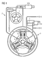
- FIG. 1 is shown in a schematic representation of substantially the high-pressure part of a common rail injection system, which is usable for an internal combustion engine, such as a diesel, gasoline or gas engine. It shows the components that provide the fuel in the rail under high pressure for the injectors.
- an internal combustion engine such as a diesel, gasoline or gas engine. It shows the components that provide the fuel in the rail under high pressure for the injectors.
- the fuel is first of a (in FIG. 1 not shown tank) via a fuel inlet A of a fuel feed pump 1 is supplied.
- the fuel feed pump 1 is connected via its output to the input of a controllable volume flow control valve VCV.
- an admission pressure control valve 5 is connected in parallel to the fuel advance pump, via which excess fuel can be returned to the low pressure area.
- the output of the volume flow control valve VCV is connected to a high-pressure pump 8, which generates a very high fuel pressure in the rail, depending on the application example, 800 ... 2000 bar.
- the high-pressure pump 8 has three displacement units 3.
- a flushing / lubricating valve 6 is installed in the inlet region of the high-pressure pump 8, via which the fuel feed pump 1 flushes and lubricates the high-pressure pump 8 with fuel.
- a high pressure control valve PCV is arranged at the high pressure outlet of the high pressure pump 8.
- the high-pressure control valve PCV preferably controls the high fuel pressure in the rail by means of a PI controller.
- a gap filter 7 is connected downstream of the high-pressure control valve PCV in order to filter out solid suspended particles in the fuel before the fuel is fed via a high-pressure connection B to a downstream fuel reservoir with injectors connected thereto.
- a branch for a fuel return C is provided in order to return excess fuel back into the low-pressure region.
- FIG. 2 shows a known two-dimensional pilot map, which is used to control the flow control valve VCV use.
- the engine speed N is plotted on the X axis and the injection quantity MF (mass of fuel) is plotted on the Y axis.
- the pilot control value for the volume flow control valve VCV is then read for a current speed N and a load-dependent predetermined injection quantity MF on the Z axis as a percentage value (% value) of the pulse width modulated signal with which the volume flow control valve is controlled.
- the pilot control characteristic initially serves for the volumetric flow control valve VCV as a presetting value, which can still be adapted with the aid of an adaptation value in order to obtain an exact valve position depending on the actual parameters of the injection system.
- the pilot control value can also be stored as a table.
- the characteristic values are also indicated in the table as percentages from the maximum opening angle of the volume flow control valve VCV.
- the valve position of the volume flow control valve VCV is controlled by means of a pulse width modulation (PWM values).
- PWM values pulse width modulation
- an adaptation value from the adaptation characteristic field is added to the pilot control value of the pilot control map to determine the PWM value for a current operating point.
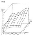
- FIG. 3 shows an embodiment of the adaptation map according to the invention.
- the adaptation map thus has - in this special case - the same axes as the pilot control map of FIG. 2 ,
- the speed X is plotted on the X axis and the injection quantity MF on the Y axis.
- the adaptation value A can then be read on the Z axis as a percentage value from the maximum opening angle of the volume flow control valve VCV.
- the adaptation values are stored in the adaptation characteristic field as a function of in each case two of the following operating parameters: the injection quantity MF, the engine torque, the engine speed N and / or the load TQI.
- the injection quantity MF the injection quantity MF
- the engine torque the engine speed N
- the load TQI the load of the internal combustion engine
- two of these parameters can be used to produce an exact assignment of the adaptation value to the load of the internal combustion engine via the two-dimensional adaptation characteristic field. It is thus avoided that the high-pressure pump is promoted too much or too little fuel in the fuel tank of the internal combustion engine by an incorrect opening angle of the flow control valve VCV.
- the control according to the invention advantageously compensates for manufacturing tolerances of the individual components of the injection system of the internal combustion engine.
- the values of the adaptation characteristic field are preferably linearly interpolated.
- intermediate values can also be determined with a simple linear regression, so that the adaptation values are determined more accurately.
- the adaptation values for the individual load points in the two-dimensional adaptation characteristic field are continuously adapted, so that an automatic adaptation results for the volume flow control valve VCV. This results in an exact load point-dependent adaptation to the toleranced built-in components, which also works independently of their aging and wear.
- the controlled variable of the PI regulator of the pressure regulating valve is monitored by a control unit. If the controlled variable of the PI controller exceeds a defined threshold, the control unit enters a corresponding adaptation value into the adaptation characteristic field for the present operating point in accordance with the parameters of the axis of the adaptation characteristic field. He adaptation value is selected so that when controlling the volume flow control valve VCV with the pilot value from the pilot map and the adaptation value from the adaptation map so much fuel is conveyed into the fuel tank that the control variable of the PI controller again gets below the threshold.
- the adaptation value is lowered or increased, for example, when the threshold for the controller value is exceeded or undershot by a specified value or a specified percentage.
- the optimum adaptation to the required fuel quantity ensures that the low-pressure system becomes insensitive to the heat input via the fuel return system.
- the return system can therefore be connected in the vicinity, or directly to the high-pressure pump, since the fuel is no longer heated.
- a further advantage is also seen in the fact that the control quality is improved in particular in injection methods with a multiple injection, since the pressure fluctuations in the rail are minimized due to a wrong or unstable valve position.
- FIG. 4 shows an embodiment of the invention with a device for controlling the load-point-dependent volume flow in a common rail injection system. It has a program-controlled control unit 10, which is provided with a program memory 11, a memory 12 for a first pilot control map for the pressure control valve and a second pilot control map for the flow control valve and is connected to a memory 13 for an adaptation map.
- the control unit 10 executes a program which controls or controls the connected components fuel feed pump 1, high-pressure pump 8, high-pressure control valve PCV and the volume flow control valve VCV, etc. It is provided that a PI controller 9 controls the high-pressure control valve PCV according to the predetermined first pilot control map.
- the PI controller 9 is connected to the control unit 10 and reports the current control value of the high-pressure control valve to the control unit 10.
- the control unit 10 is connected to sensors that detect the operating parameters, in particular the speed, the injection quantity, the engine torque and the load.
- the volume flow control valve VCV is controlled in its valve position by means of the second pilot control map and the two-dimensional Adaptionskennfeldes so that the exact amount of fuel required for each current load point is provided. By this load point-dependent control of the volume flow control valve VCV is achieved in an advantageous manner that the fuel return amount is minimized and thus in particular a heating of the fuel in the tank is avoided.
- the high-pressure pump which is driven by a toothed belt or a mechanical clutch, absorbs less energy and thus reduces the power consumption of the high-pressure pump.
- the result is a high engine performance and / or a reduced fuel consumption.
Description
Die Erfindung geht von einem Verfahren beziehungsweise von einer Vorrichtung zur Steuerung des Volumenstroms in einem Common Rail Einspritzsystem einer Brennkraftmaschine gemäß den nebengeordneten Ansprüchen 1 und 8 aus. Es ist schon bekannt, dass bei Einspritzsystemen, bei denen der Kraftstoff direkt in einen Zylinder einer Brennkraftmaschine eingespritzt wird, der Raildruck durch Absteuerung im Hochdruckbereich mit einem Druckregelventil geregelt wird. Der lastpunktabhängige Volumenstrom wird dagegen von einem Volumenstromregelventil gesteuert. Die Steuerung ist dabei so ausgebildet, dass die Hochdruckpumpe möglichst nur den aktuellen Bedarf an Kraftstoff liefert. Mit dieser Vorgehensweise soll erreicht werden, dass einerseits die Leistungsaufnahme der Hochdruckpumpe gering gehalten wird. Andererseits wird auch die Kraftstoffrücklaufmenge und die dabei in den Niederdruckbereich eingebrachte Wärmemenge minimiert.The invention is based on a method or a device for controlling the volume flow in a common rail injection system of an internal combustion engine according to the
Zur Steuerung des Volumenstromventils wird ein zweidimensionales Vorsteuerkennfeld verwendet, das von der Einspritzmenge und der Motordrehzahl geführt wird. In diesem Vorsteuerkennfeld bilden die Einspritzmenge und die Motordrehzahl ein Maß für den aktuellen Volumenstrombedarf, der einer bestimmten Last für die Brennkraftmaschine entspricht. Aufgrund von Bauteilestreuungen ist es erforderlich zusätzlich ein Kennfeld mit Adaptionswerten für die Steuerung des Volumenstromregelventils vorzusehen. Insbesondere da sich der Volumenstrombedarf durch verschleißbedingte höhere interne Leckagen über der Lebenszeit des Systems erhöhen kann. Das bisher verwendete Adaptions-Kennfeld ist lediglich vom Raildruck abhängig. Somit wird zusätzlich zum Vorsteuerkennfeld das eindimensionale Adaptionskennfeld zur Steuerung des Volumenstromregelventils verwendet.To control the volume flow valve, a two-dimensional pilot control map is used, which is guided by the injection quantity and the engine speed. In this pilot control map, the injection quantity and the engine speed form a measure of the current volume flow requirement, which corresponds to a specific load for the internal combustion engine. Due to component variations, it is necessary to additionally provide a map with adaptation values for the control of the volume flow control valve. In particular, since the volume flow requirement can increase due to wear-induced higher internal leaks over the lifetime of the system. The previously used adaptation map is only dependent on the rail pressure. Thus, in addition to the pilot control map, the one-dimensional adaptation map is used to control the flow control valve.
Liefert das Vorsteuerkennfeld (z. B. durch verschleißbedingten höheren Volumenstrombedarf) zu geringe Werte, wird durch das Verhalten des Raildruckreglers (hohe positive Regelabweichung, da die Menge zur Aufrechterhaltung des Druckes nicht ausreicht) eine Adaption des Volumenstromregelventilsansteuerungswertes ausgelöst, bis die Menge wieder ausreichend ist.If the pilot control map (eg due to wear-induced higher volumetric flow requirement) is too low, the behavior of the rail pressure regulator (high positive control deviation, since the amount is insufficient to maintain the pressure) triggers an adaptation of the volumetric flow control valve actuation value until the quantity is sufficient again ,
Dieser Adaptionswert wird bisher in Abhängigkeit des Raildruckes gespeichert und bei jedem Lastpunkt, der mit diesem Druck gefahren wird, benutzt. Das Volumenstromregelventil wird somit immer mit dem Vorsteuerwert plus dem Adaptionswert gesteuert.This adaptation value has hitherto been stored as a function of the rail pressure and used at each load point which is driven at this pressure. The volume flow control valve is thus always controlled with the pre-control value plus the adaptation value.
Die Zuordnung des Lastpunktes und des Raildruckes ist aber nicht eindeutig. Ein und derselbe Druck wird an verschiedenen Lastpunkten verwendet. Dies kann dazu führen, dass an einem Lastpunkt der Adaptionswert grundlos benutzt wird, weil an diesem Lastpunkt der gleiche Raildruck gefahren wird, wie an einem anderen Lastpunkt, bei dem die Adaption erfolgte.The assignment of the load point and the rail pressure is not unique. One and the same pressure is used at different load points. This can result in the adaptation value being used without reason at a load point because the same rail pressure is traveled at this load point as at another load point at which the adaptation took place.
Die Folge ist, dass beispielsweise an Stelle des korrekten Adaptionswertes ein falscher, zu hoher Adaptionswert aus der Kennlinie ausgelesen und damit zuviel Kraftstoff bereitgestellt wird. Die druckabhängige Steuerung führt somit in den genannten Fällen zur Förderung einer falschen Kraftstoffmenge.The consequence is that, for example, instead of the correct adaptation value, a wrong, too high adaptation value is read from the characteristic curve and thus too much fuel is provided. The pressure-dependent control thus leads in the cases mentioned to promote a wrong amount of fuel.
Der Erfindung liegt die Aufgabe zu Grunde, die Steuerung des Volumenstromregelventils so zu verbessern, dass möglichst nur die erforderliche Kraftstoffmenge bereitgestellt wird. Diese Aufgabe wird mit den Merkmalen der nebengeordneten Ansprüche 1 und 8 gelöst.The invention is based on the object to improve the control of the flow control valve so that as possible only the required amount of fuel is provided. This object is achieved with the features of the
Bei dem erfindungsgemäßen Verfahren zur Steuerung des lastpunktabhängigen Volumenstroms in einem KraftstoffEinspritzsystem einer Brennkraftmaschine mit den kennzeichnenden Merkmalen der nebengeordneten Ansprüche 1 und 8 besteht der Vorteil darin, dass zur Bestimmung der Ventilstellung des Volumenstromregelventils zusätzlich zum Vorsteuerkennfeld ein zweidimensionales Adaptions-Kennfeld verwendet wird. Als besonders vorteilhaft wird dabei angesehen, dass bei dem zweidimensionalen Adaptions-Kennfeld die Adaptionswerte für das Volumenstromregelventil in Abhängigkeit von zwei Betriebsparametern der Brennkraftmaschine vorgegeben werden.In the inventive method for controlling the load-point-dependent volume flow in a fuel injection system of an internal combustion engine with the characterizing Features of the
Durch die in den abhängigen Ansprüchen aufgeführten Maßnahmen sind vorteilhafte Weiterbildungen und Verbesserungen des in den nebengeordneten Ansprüche 1 und 8 gegeben. Als besonders vorteilhaft wird angesehen, dass in dem Adaptions-Kennfeld die Adaptionswerte für die Ventilstellung in Abhängigkeit von zwei der nachfolgend genannten vier Betriebsparametern Einspritzmenge, Motordrehmoment, Motordrehzahl und Last gebildet werden kann. Bei diesen möglichen Zweierkombinationen von Betriebsparametern ergeben sich in vorteilhafter Weise Adaptionswerte, die auf den jeweiligen Lastpunkt angepasst sind.The measures listed in the dependent claims advantageous refinements and improvements of the
Eine besonders günstige Lösung wird auch darin gesehen, dass die Adaptionswerte in einem Adaptionskennfeld abgelegt sind, das die Adaptionswerte in Abhängigkeit von den beiden Betriebsparametern Motordrehzahl und Einspritzmenge wiedergibt. Denn mit diesen beiden Betriebsparametern lässt sich ein eineindeutiger Adaptionswert für das Volumenstromregelventil vorgeben.A particularly favorable solution is also seen in the fact that the adaptation values are stored in an adaptation characteristic map which reproduces the adaptation values as a function of the two operating parameters engine speed and injection quantity. Because with these two operating parameters can be a one-time adaptation value for the flow control valve specify.
Es ist weiterhin vorgesehen, sowohl bei dem Vorsteuerkennfeld, als auch bei dem Adaptionskennfeld die gleichen Betriebsparameter für die Achsen des Kennfeldes zu verwenden. Diese Vorgehensweise vereinfacht die Steuerung des Volumenstromregelventils, da die beiden Betriebsparameter bereits für das Vorsteuerkennfeld verwendet werden und damit eine Übereinstimmung der Lastpunkte gegeben ist.It is further provided to use the same operating parameters for the axes of the characteristic map both in the pilot control map and in the adaptation map. This procedure simplifies the control of the volume flow control valve, since the two operating parameters are already used for the pilot control map and thus a match of the load points is given.
Da im Adaptions-Kennfeld nicht in jedem Fall die gespeicherten Werte dem aktuellen Lastpunkt entsprechen, ist vorgesehen, dass zwischen zwei gespeicherten, benachbarten Werten des Adaptionskennfeldes interpoliert wird.Since the stored values do not always correspond to the current load point in the adaptation map, it is provided that interpolation takes place between two stored, adjacent values of the adaptation map.
Vorzugsweise wird eine lineare Interpolation der Adaptionswerte durchgeführt, für die die bekannten Algorithmen verwendet werden können.Preferably, a linear interpolation of the adaptation values is carried out, for which the known algorithms can be used.
In einer weiteren bevorzugten Ausführungsform werden die Werte des Adoptionskennfeldes während des Betriebs des Einspritzsystems angepasst. Vorzugsweise werden die Werte des Adaptionskennfeldes geändert, wenn die Regelgröße des Reglers des Druckregelventils eine festgelegte Schwelle über- oder unterschreitet.In a further preferred embodiment, the values of the adoption map are adjusted during operation of the injection system. Preferably, the values of the adaptation characteristic field are changed when the controlled variable of the regulator of the pressure regulating valve exceeds or falls below a defined threshold.
Die Vorrichtung ist in vorteilhafter Weise bei einem Diesel-, Benzin- oder Gasmotor anwendbar.The device is advantageously applicable to a diesel, gasoline or gas engine.
Ein Ausführungsbeispiel der Erfindung ist in der Zeichnung dargestellt und wird in der nachfolgenden Zeichnung näher erläutert.
- Figur 1
- zeigt in schematischer Darstellung den Hochdruckteil eines Common Rail Einspritzsystems,
Figur 2- zeigt ein zweidimensionales Vorsteuerkennfeld nach dem Stand der Technik,
Figur 3- zeigt ein Ausführungsbeispiel der Erfindung mit einem zweidimensionales Adaptionskennfeld und
- Figur 4
- zeigt ein Blockschaltbild einer erfindungsgemäßen Vorrichtung.
- FIG. 1
- shows a schematic representation of the high pressure part of a common rail injection system,
- FIG. 2
- shows a two-dimensional pilot control map according to the prior art,
- FIG. 3
- shows an embodiment of the invention with a two-dimensional adaptation map and
- FIG. 4
- shows a block diagram of a device according to the invention.
In
Der Kraftstoff wird zunächst von einem (in
Am Hochdruckausgang der Hochdruckpumpe 8 ist ein Hochdruckregelventil PCV angeordnet. Das Hochdruckregelventil PCV regelt vorzugsweise mittels eines PI-Reglers den Kraftstoffhochdruck im Rail. Ausgangsseitig ist dem Hochdruckregelventil PCV ein Spaltfilter 7 nachgeschaltet, um feste Schwebteilchen im Kraftstoff auszufiltern, bevor der Kraftstoff über einen Hochdruckanschluss B einem nachgeschalteten Kraftstoffspeicher mit daran angeschlossenen Injektoren zugeführt wird. Vor dem Eingang des Hochdruckregelventils PCV ist ein Abzweig für einen Kraftstoffrücklauf C vorgesehen, um überschüssigen Kraftstoff wieder in den Niederdruckbereich zurückzuführen.At the high pressure outlet of the
Bei der Darstellung des Vorsteuerkennfeldes gemäß
Alternativ kann der Vorsteuerkennwert auch als Tabelle abgelegt sein. In der Tabelle werden ebenfalls abhängig von der Motordrehzahl N und der Einspritzmenge MF die Kennwerte als Prozentwerte vom maximalen Öffnungswinkel des Volumenstromregelventils VCV angegeben.Alternatively, the pilot control value can also be stored as a table. Depending on the engine speed N and the injection quantity MF, the characteristic values are also indicated in the table as percentages from the maximum opening angle of the volume flow control valve VCV.
Die Ventilstellung des Volumenstromregelventils VCV wird mit Hilfe einer Pulsweitenmodulation (PWM-Werte) gesteuert. Um eine Adaption der Ventilstellung zu erreichen, wird zur Ermittlung des PWM-Wertes für einen aktuellen Betriebspunkt ein Adaptionswert aus dem Adaptionskennfeld zu dem Vorsteuerkennwert des Vorsteuerkennfelds addiert.The valve position of the volume flow control valve VCV is controlled by means of a pulse width modulation (PWM values). In order to achieve an adaptation of the valve position, an adaptation value from the adaptation characteristic field is added to the pilot control value of the pilot control map to determine the PWM value for a current operating point.
Erfindungsgemäß wird vorgeschlagen, das Adaptionskennfeld in Abhängigkeit von zwei Betriebsparameter zweidimensional auszubilden.According to the invention, it is proposed to design the adaptation map in two dimensions as a function of two operating parameters.
In alternativer Ausgestaltung der Erfindung ist vorgesehen, dass die Adaptionswerte im Adaptionskennfeld in Abhängigkeit von jeweils zwei der folgenden Betriebsparameter abgelegt werden: die Einspritzmenge MF, das Motordrehmoment, die Motordrehzahl N und/oder die Last TQI. Durch jeweils zwei dieser Parameter kann über das zweidimensionale Adaptionskennfeld eine genaue Zuordnung des Adaptionswertes zur Last der Brennkraftmaschine hergestellt werden. Es wird damit vermieden, dass durch einen falschen Öffnungswinkel des Volumenstromregelventils VCV die Hochdruckpumpe zu viel oder zu wenig Kraftstoff in den Kraftstoffspeicher der Brennkraftmaschine gefördert wird. Die erfindungsgemäße Steuerung gleicht in vorteilhafter Weise Fertigungstoleranzen der einzelnen Baugruppen des Einspritzsystems der Brennkraftmaschine aus.In an alternative embodiment of the invention, it is provided that the adaptation values are stored in the adaptation characteristic field as a function of in each case two of the following operating parameters: the injection quantity MF, the engine torque, the engine speed N and / or the load TQI. In each case two of these parameters can be used to produce an exact assignment of the adaptation value to the load of the internal combustion engine via the two-dimensional adaptation characteristic field. It is thus avoided that the high-pressure pump is promoted too much or too little fuel in the fuel tank of the internal combustion engine by an incorrect opening angle of the flow control valve VCV. The control according to the invention advantageously compensates for manufacturing tolerances of the individual components of the injection system of the internal combustion engine.
Für die Ermittlung der Adaptionswerte ist des Weiteren vorgesehen, dass die Werte des Adaptionskennfeldes vorzugsweise linear interpoliert werden. Dadurch lassen sich mit einer einfachen linearen Regression auch Zwischenwerte ermitteln, so dass die Adaptionswerte genauer ermittelt werden.For the determination of the adaptation values, it is further provided that the values of the adaptation characteristic field are preferably linearly interpolated. As a result, intermediate values can also be determined with a simple linear regression, so that the adaptation values are determined more accurately.
Erfindungsgemäß ist weiter vorgesehen, dass die Adaptionswerte für die einzelnen Lastpunkte in dem zweidimensionalen Adaptionskennfeld kontinuierlich angepasst werden, so dass sich eine automatische Adaption für das Volumenstromregelventil VCV ergibt. Dadurch ergibt sich eine exakte lastpunktabhängige Anpassung an die toleranzbehafteten verbauten Komponenten, die auch von deren Alterung und Verschleiß unabhängig funktioniert.According to the invention, it is further provided that the adaptation values for the individual load points in the two-dimensional adaptation characteristic field are continuously adapted, so that an automatic adaptation results for the volume flow control valve VCV. This results in an exact load point-dependent adaptation to the toleranced built-in components, which also works independently of their aging and wear.
Zur Adaption der Adaptionswerte des Adaptionskennfeldes wird die Regelgröße des PI-Regler des Druckregelventils von einer Steuereinheit überwacht. Überschreitet die Regelgröße des PI-Reglers eine festgelegte Schwelle, so wird von der Steuereinheit ein entsprechender Adaptionswert in das Adaptionskennfeld zu dem vorliegenden Betriebspunkt entsprechend den Parametern der Achse des Adaptionskennfeldes eingetragen. Er Adaptionswert ist so gewählt, dass bei Ansteuerung des Volumenstromregelventils VCV mit dem Vorsteuerwert aus dem Vorsteuerkennfeld und dem Adaptionswert aus dem Adaptionskennfeld so viel Kraftstoff in den Kraftstoffspeicher befördert wird, dass die Regelgröße des PI-Reglers wieder unter die Schwelle gelangt. Der Adaptionswert wird beispielsweise bei Überschreiten oder Unterschreiten der Schwelle für den Reglerwert um einen festgelegten Wert oder einen festgelegten Prozentsatz erniedrigt bzw. erhöht.To adapt the adaptation values of the adaptation characteristic field, the controlled variable of the PI regulator of the pressure regulating valve is monitored by a control unit. If the controlled variable of the PI controller exceeds a defined threshold, the control unit enters a corresponding adaptation value into the adaptation characteristic field for the present operating point in accordance with the parameters of the axis of the adaptation characteristic field. He adaptation value is selected so that when controlling the volume flow control valve VCV with the pilot value from the pilot map and the adaptation value from the adaptation map so much fuel is conveyed into the fuel tank that the control variable of the PI controller again gets below the threshold. The adaptation value is lowered or increased, for example, when the threshold for the controller value is exceeded or undershot by a specified value or a specified percentage.
Durch die optimale Anpassung an die erforderliche Kraftstoffmenge ist sichergestellt, dass das Niederdrucksystem unempfindlich wird gegen den Wärmeeintrag über das Kraftstoffrücklaufsystem. Das Rücklaufsystem kann daher in der Nähe, beziehungsweise direkt an der Hochdruckpumpe angeschlossen werden, da der Kraftstoff nicht mehr aufgeheizt wird.The optimum adaptation to the required fuel quantity ensures that the low-pressure system becomes insensitive to the heat input via the fuel return system. The return system can therefore be connected in the vicinity, or directly to the high-pressure pump, since the fuel is no longer heated.
Ein weiterer Vorteil wird auch darin gesehen, dass die Regelgüte insbesondere bei Einspritzverfahren mit einer Mehrfacheinspritzung verbessert wird, da die Druckschwankungen im Rail auf Grund einer falschen oder instabilen Ventilstellung minimiert werden.A further advantage is also seen in the fact that the control quality is improved in particular in injection methods with a multiple injection, since the pressure fluctuations in the rail are minimized due to a wrong or unstable valve position.
Claims (10)
- Method for controlling the volumetric flow in a common rail injection system in an internal combustion engine, the rail pressure being produced by means of a high pressure pump (8) and being set in the rail by a regulatable high pressure regulation valve (PCV) and the volumetric flow being determined by the valve position of a controllable volumetric flow regulation valve (VCV), which is controlled by means of a precontrol characteristic field and an adaptation characteristic field as a function of an operating parameter of the internal combustion engine, characterised in that the adaptation characteristic field is configured as two-dimensional, the adaptation values for the valve position being predefined in the adaptation characteristic field as a function of two operating parameters of the internal combustion engine.
- Method according to claim 1, characterised in that in the adaptation characteristic field the adaptation values for the valve position are determined as a function of two of the following operating parameters respectively:the mass of fuel (MF),the engine speed (N) and/orthe engine torque or load (TQI).
- Method according to claim 1 or 2, characterised in that the adaptation values are stored in the adaptation characteristic field with the operating parameters engine speed (N) and mass of fuel (MF).
- Method according to claim 3, characterised in that the adaptation characteristic field has the same parameter axes as the precontrol characteristic field.
- Method according to one of the preceding claims, characterised in that a current adaptation value is interpolated from adjacent values of the adaptation characteristic field.
- Method according to claim 5, characterised in that the interpolation is linear.
- Method according to one of claims 1 to 6, characterised in that the adaptation values of the adaptation characteristic field are adjusted as a function of the regulation value of the regulator (9) of the high pressure regulation valve (PCV).
- Device for controlling the load-point-dependent volumetric flow in a common rail injection system in an internal combustion engine, with a high pressure pump (8), a regulatable high pressure regulation valve (PCV), a controllable volumetric flow regulation valve (VCV), a programmable control unit (10) and a storage unit (13) according to one of the preceding claims, characterised in that a two-dimensional adaptation characteristic field for the volumetric flow regulation valve (VCV) is stored in the storage unit (13) and that the control unit controls the valve position of the volumetric flow regulation valve (VCV) as a function of a precontrol characteristic field and the adaptation characteristic field as a function of two operating parameters of the internal combustion engine.
- Device according to claim 8, characterised in that the adaptation values are stored in the adaptation characteristic field as a function of the speed (N) of the internal combustion engine and the mass of fuel (MF).
- Device according to one of claims 8 or 9, characterised in that the control unit (10) detects a regulation value of the regulator (9) of the high pressure regulation valve (PCV) and, if said value exceeds or is below comparison thresholds, reduces or increases the adaptation value in the adaptation characteristic field.
Applications Claiming Priority (2)
| Application Number | Priority Date | Filing Date | Title |
|---|---|---|---|
| DE102004009616 | 2004-02-27 | ||
| DE102004009616A DE102004009616A1 (en) | 2004-02-27 | 2004-02-27 | Method and device for controlling the volume flow in a fuel injection system of an internal combustion engine |
Publications (3)
| Publication Number | Publication Date |
|---|---|
| EP1568874A2 EP1568874A2 (en) | 2005-08-31 |
| EP1568874A3 EP1568874A3 (en) | 2011-01-05 |
| EP1568874B1 true EP1568874B1 (en) | 2012-07-11 |
Family
ID=34745300
Family Applications (1)
| Application Number | Title | Priority Date | Filing Date |
|---|---|---|---|
| EP05100301A Expired - Fee Related EP1568874B1 (en) | 2004-02-27 | 2005-01-19 | Method and apparatus for controlling the volume flow in a fuel injection system of an internal combustion engine |
Country Status (3)
| Country | Link |
|---|---|
| US (1) | US7163001B2 (en) |
| EP (1) | EP1568874B1 (en) |
| DE (1) | DE102004009616A1 (en) |
Families Citing this family (14)
| Publication number | Priority date | Publication date | Assignee | Title |
|---|---|---|---|---|
| DE102005026441B4 (en) * | 2005-06-08 | 2009-11-12 | Continental Automotive Gmbh | Method for adapting the pilot control map of a volume-flow-controlled diesel common rail pump |
| DE102005058966B3 (en) * | 2005-12-09 | 2007-08-02 | Siemens Ag | Method for adapting a precontrol in a pressure control for a common-rail injection system for an internal combustion engine and means for carrying out the method |
| DE102006004602B3 (en) * | 2006-02-01 | 2007-05-31 | Siemens Ag | Pressure control valve`s pre-controlled engine characteristics approximating method, involves adjusting stored pre-controlled engine characteristics by regression process under inclusion of measured pressure and determined control flow |
| DE102006018164B3 (en) * | 2006-04-19 | 2007-08-30 | Siemens Ag | Fuel injection system controlling method for internal combustion engine, involves adjusting volume flow control valve depending on control value for volume flow control valve and controlling of pressure control valve |
| DE102006032466B3 (en) * | 2006-07-13 | 2007-09-13 | Siemens Ag | Fuel e.g. diesel, quantity controlling valve`s characteristic adapting method for use in motor vehicle, involves controlling quantity controlling valve with test equipment in operating point having operating parameter for providing fuel |
| DE102008021384B3 (en) * | 2008-04-29 | 2009-11-26 | Continental Aktiengesellschaft | Superimposed pressure control of the common rail system |
| DE102008048193B4 (en) | 2008-09-20 | 2023-05-04 | Volkswagen Ag | Method for determining a pilot control value for a fuel injection system of an internal combustion engine |
| DE102010030872A1 (en) * | 2010-07-02 | 2012-01-05 | Robert Bosch Gmbh | Method for determining a correction characteristic |
| US9611856B2 (en) | 2010-12-30 | 2017-04-04 | Fluid Handling Llc | Mixed theoretical and discrete sensorless converter for pump differential pressure and flow monitoring |
| US8700221B2 (en) | 2010-12-30 | 2014-04-15 | Fluid Handling Llc | Method and apparatus for pump control using varying equivalent system characteristic curve, AKA an adaptive control curve |
| DE102011006203B4 (en) | 2011-03-28 | 2016-05-04 | Continental Automotive Gmbh | Control method for adjusting a pressure in a storage injection system of an internal combustion engine |
| CA2856447C (en) | 2011-12-16 | 2019-06-04 | Fluid Handling Llc | Dynamic linear control methods and apparatus for variable speed pump control |
| DE102013009147B4 (en) * | 2013-05-31 | 2015-11-05 | Mtu Friedrichshafen Gmbh | Method for regulating a pressure and arrangement for regulating a pressure |
| CN113250841B (en) * | 2021-06-18 | 2023-05-19 | 中国北方发动机研究所(天津) | High-pressure common rail fuel injection system and rail pressure control method thereof |
Family Cites Families (8)
| Publication number | Priority date | Publication date | Assignee | Title |
|---|---|---|---|---|
| DE4120000A1 (en) * | 1991-06-18 | 1992-12-24 | Vdo Schindling | Limiting control action particularly for vehicle engine speed - having error signal integrated to generate signal that limits output if signal exceeds current error signal level |
| DE19746563A1 (en) * | 1997-10-22 | 1999-04-29 | Bosch Gmbh Robert | Fuel injection system for IC engine |
| DE59810332D1 (en) * | 1998-01-13 | 2004-01-15 | Siemens Ag | Procedure for specifying the injection pressure setpoint in accumulator injection systems |
| DE19838812C1 (en) * | 1998-08-26 | 2000-04-20 | Siemens Ag | Method and device for setting a pressure between a prefeed pump and a high pressure pump of an injection system |
| DE19946506C1 (en) * | 1999-09-28 | 2001-07-19 | Siemens Ag | Detecting failure in pressure system of IC engine fuel injection system |
| DE10155247B4 (en) * | 2001-11-09 | 2006-08-24 | Siemens Ag | Injection system with emergency function |
| DE10155249C1 (en) * | 2001-11-09 | 2003-04-24 | Siemens Ag | Fuel injection system has volumetric flow valve for regulating fuel pressure controlled in dependence on fuel model |
| DE10162989C1 (en) * | 2001-12-20 | 2003-10-09 | Siemens Ag | Circuit for regulating injection system fuel pump, derives adaptive component of desired delivery volume from integral component if integral component above threshold for defined time |
-
2004
- 2004-02-27 DE DE102004009616A patent/DE102004009616A1/en not_active Withdrawn
-
2005
- 2005-01-19 EP EP05100301A patent/EP1568874B1/en not_active Expired - Fee Related
- 2005-02-22 US US11/063,175 patent/US7163001B2/en active Active
Also Published As
| Publication number | Publication date |
|---|---|
| US20050188957A1 (en) | 2005-09-01 |
| EP1568874A3 (en) | 2011-01-05 |
| US7163001B2 (en) | 2007-01-16 |
| EP1568874A2 (en) | 2005-08-31 |
| DE102004009616A1 (en) | 2005-09-22 |
Similar Documents
| Publication | Publication Date | Title |
|---|---|---|
| EP1568874B1 (en) | Method and apparatus for controlling the volume flow in a fuel injection system of an internal combustion engine | |
| DE10162989C1 (en) | Circuit for regulating injection system fuel pump, derives adaptive component of desired delivery volume from integral component if integral component above threshold for defined time | |
| DE102004053124B4 (en) | Valve opening degree control system and common rail fuel injection system | |
| DE60009609T2 (en) | Exhaust emission control system | |
| EP1613853B1 (en) | Method for determining the injection duration in a combustion engine with a mapping value and a correction value, and method for determining the correction value | |
| EP1086307A1 (en) | Common-rail system comprising a controlled high-pressure pump as a second pressure regulator | |
| WO1997043543A1 (en) | Device and process to regulate fuel pressure in a high pressure accumulator | |
| DE19913477B4 (en) | Method for operating a fuel supply device of an internal combustion engine, in particular a motor vehicle | |
| EP2205846B1 (en) | Method for controlling a fuel injection system of an internal combustion engine | |
| DE102008000513A1 (en) | Fuel injection pressure control device for compensating individual fluctuations of the control pressure characteristic | |
| DE10157641C2 (en) | Method for controlling an internal combustion engine | |
| DE19731994A1 (en) | Method and device for controlling an internal combustion engine | |
| DE102008000772A1 (en) | Common rail fuel injection device and method for compensating a pumping characteristic of a high pressure pump | |
| DE102006018164B3 (en) | Fuel injection system controlling method for internal combustion engine, involves adjusting volume flow control valve depending on control value for volume flow control valve and controlling of pressure control valve | |
| DE102007052092B4 (en) | Method and fuel system for controlling the fuel supply for an internal combustion engine | |
| DE10036772C2 (en) | Method for operating a fuel metering system of a direct injection internal combustion engine | |
| EP1281860A2 (en) | Injection System for an Internal Combustion Engine and Method for Operating the Same | |
| DE102008017160B3 (en) | Method for determining the effective compressibility module of an injection system | |
| WO2001069067A1 (en) | Method for operating an internal combustion engine | |
| DE102015205586B3 (en) | High-pressure injection device for an internal combustion engine | |
| DE102013000060B3 (en) | Method of operating internal combustion engine, involves dividing high pressure pump associated with suction throttle into units, and controlling each unit by separate control loop | |
| DE10305525A1 (en) | Method and device for adapting the pressure wave correction in a high-pressure injection system of a motor vehicle while driving | |
| EP2718556B1 (en) | Method for controlling rail pressure | |
| DE10036153B4 (en) | Method and device for controlling an internal combustion engine | |
| WO2016059047A1 (en) | Method for operating a fuel-supply system for an internal combustion engine |
Legal Events
| Date | Code | Title | Description |
|---|---|---|---|
| PUAI | Public reference made under article 153(3) epc to a published international application that has entered the european phase |
Free format text: ORIGINAL CODE: 0009012 |
|
| AK | Designated contracting states |
Kind code of ref document: A2 Designated state(s): AT BE BG CH CY CZ DE DK EE ES FI FR GB GR HU IE IS IT LI LT LU MC NL PL PT RO SE SI SK TR |
|
| AX | Request for extension of the european patent |
Extension state: AL BA HR LV MK YU |
|
| RAP1 | Party data changed (applicant data changed or rights of an application transferred) |
Owner name: CONTINENTAL AUTOMOTIVE GMBH |
|
| PUAL | Search report despatched |
Free format text: ORIGINAL CODE: 0009013 |
|
| AK | Designated contracting states |
Kind code of ref document: A3 Designated state(s): AT BE BG CH CY CZ DE DK EE ES FI FR GB GR HU IE IS IT LI LT LU MC NL PL PT RO SE SI SK TR |
|
| AX | Request for extension of the european patent |
Extension state: AL BA HR LV MK YU |
|
| RIC1 | Information provided on ipc code assigned before grant |
Ipc: F02D 41/14 20060101ALI20101126BHEP Ipc: F02D 41/38 20060101AFI20050527BHEP |
|
| 17P | Request for examination filed |
Effective date: 20110705 |
|
| AKX | Designation fees paid |
Designated state(s): DE FR |
|
| RIC1 | Information provided on ipc code assigned before grant |
Ipc: F02D 41/38 20060101AFI20110831BHEP Ipc: F02D 41/14 20060101ALI20110831BHEP |
|
| GRAP | Despatch of communication of intention to grant a patent |
Free format text: ORIGINAL CODE: EPIDOSNIGR1 |
|
| GRAS | Grant fee paid |
Free format text: ORIGINAL CODE: EPIDOSNIGR3 |
|
| GRAA | (expected) grant |
Free format text: ORIGINAL CODE: 0009210 |
|
| AK | Designated contracting states |
Kind code of ref document: B1 Designated state(s): DE FR |
|
| REG | Reference to a national code |
Ref country code: DE Ref legal event code: R096 Ref document number: 502005012899 Country of ref document: DE Effective date: 20120906 |
|
| PLBE | No opposition filed within time limit |
Free format text: ORIGINAL CODE: 0009261 |
|
| STAA | Information on the status of an ep patent application or granted ep patent |
Free format text: STATUS: NO OPPOSITION FILED WITHIN TIME LIMIT |
|
| 26N | No opposition filed |
Effective date: 20130412 |
|
| REG | Reference to a national code |
Ref country code: DE Ref legal event code: R097 Ref document number: 502005012899 Country of ref document: DE Effective date: 20130412 |
|
| REG | Reference to a national code |
Ref country code: FR Ref legal event code: PLFP Year of fee payment: 12 |
|
| REG | Reference to a national code |
Ref country code: FR Ref legal event code: PLFP Year of fee payment: 13 |
|
| REG | Reference to a national code |
Ref country code: FR Ref legal event code: PLFP Year of fee payment: 14 |
|
| PGFP | Annual fee paid to national office [announced via postgrant information from national office to epo] |
Ref country code: DE Payment date: 20180131 Year of fee payment: 14 |
|
| REG | Reference to a national code |
Ref country code: DE Ref legal event code: R119 Ref document number: 502005012899 Country of ref document: DE |
|
| PG25 | Lapsed in a contracting state [announced via postgrant information from national office to epo] |
Ref country code: DE Free format text: LAPSE BECAUSE OF NON-PAYMENT OF DUE FEES Effective date: 20190801 |
|
| REG | Reference to a national code |
Ref country code: DE Ref legal event code: R081 Ref document number: 502005012899 Country of ref document: DE Owner name: VITESCO TECHNOLOGIES GMBH, DE Free format text: FORMER OWNER: CONTINENTAL AUTOMOTIVE GMBH, 30165 HANNOVER, DE |
|
| PGFP | Annual fee paid to national office [announced via postgrant information from national office to epo] |
Ref country code: FR Payment date: 20210121 Year of fee payment: 17 |
|
| PG25 | Lapsed in a contracting state [announced via postgrant information from national office to epo] |
Ref country code: FR Free format text: LAPSE BECAUSE OF NON-PAYMENT OF DUE FEES Effective date: 20220131 |