EP2192299B1 - Accouplement d'arbres dans une éolienne - Google Patents
Accouplement d'arbres dans une éolienne Download PDFInfo
- Publication number
- EP2192299B1 EP2192299B1 EP09175698.1A EP09175698A EP2192299B1 EP 2192299 B1 EP2192299 B1 EP 2192299B1 EP 09175698 A EP09175698 A EP 09175698A EP 2192299 B1 EP2192299 B1 EP 2192299B1
- Authority
- EP
- European Patent Office
- Prior art keywords
- shaft
- recessed portion
- wind turbine
- rotor
- gearbox input
- Prior art date
- Legal status (The legal status is an assumption and is not a legal conclusion. Google has not performed a legal analysis and makes no representation as to the accuracy of the status listed.)
- Not-in-force
Links
- 238000000034 method Methods 0.000 description 3
- 238000012423 maintenance Methods 0.000 description 2
- 230000001419 dependent effect Effects 0.000 description 1
- 238000012986 modification Methods 0.000 description 1
- 230000004048 modification Effects 0.000 description 1
Images


Classifications
-
- F—MECHANICAL ENGINEERING; LIGHTING; HEATING; WEAPONS; BLASTING
- F16—ENGINEERING ELEMENTS AND UNITS; GENERAL MEASURES FOR PRODUCING AND MAINTAINING EFFECTIVE FUNCTIONING OF MACHINES OR INSTALLATIONS; THERMAL INSULATION IN GENERAL
- F16D—COUPLINGS FOR TRANSMITTING ROTATION; CLUTCHES; BRAKES
- F16D1/00—Couplings for rigidly connecting two coaxial shafts or other movable machine elements
- F16D1/06—Couplings for rigidly connecting two coaxial shafts or other movable machine elements for attachment of a member on a shaft or on a shaft-end
- F16D1/08—Couplings for rigidly connecting two coaxial shafts or other movable machine elements for attachment of a member on a shaft or on a shaft-end with clamping hub; with hub and longitudinal key
- F16D1/09—Couplings for rigidly connecting two coaxial shafts or other movable machine elements for attachment of a member on a shaft or on a shaft-end with clamping hub; with hub and longitudinal key with radial clamping due to axial loading of at least one pair of conical surfaces
- F16D1/093—Couplings for rigidly connecting two coaxial shafts or other movable machine elements for attachment of a member on a shaft or on a shaft-end with clamping hub; with hub and longitudinal key with radial clamping due to axial loading of at least one pair of conical surfaces using one or more elastic segmented conical rings forming at least one of the conical surfaces, the rings being expanded or contracted to effect clamping
- F16D1/095—Couplings for rigidly connecting two coaxial shafts or other movable machine elements for attachment of a member on a shaft or on a shaft-end with clamping hub; with hub and longitudinal key with radial clamping due to axial loading of at least one pair of conical surfaces using one or more elastic segmented conical rings forming at least one of the conical surfaces, the rings being expanded or contracted to effect clamping with clamping effected by ring contraction only
-
- F—MECHANICAL ENGINEERING; LIGHTING; HEATING; WEAPONS; BLASTING
- F03—MACHINES OR ENGINES FOR LIQUIDS; WIND, SPRING, OR WEIGHT MOTORS; PRODUCING MECHANICAL POWER OR A REACTIVE PROPULSIVE THRUST, NOT OTHERWISE PROVIDED FOR
- F03D—WIND MOTORS
- F03D15/00—Transmission of mechanical power
-
- F—MECHANICAL ENGINEERING; LIGHTING; HEATING; WEAPONS; BLASTING
- F03—MACHINES OR ENGINES FOR LIQUIDS; WIND, SPRING, OR WEIGHT MOTORS; PRODUCING MECHANICAL POWER OR A REACTIVE PROPULSIVE THRUST, NOT OTHERWISE PROVIDED FOR
- F03D—WIND MOTORS
- F03D15/00—Transmission of mechanical power
- F03D15/10—Transmission of mechanical power using gearing not limited to rotary motion, e.g. with oscillating or reciprocating members
-
- F—MECHANICAL ENGINEERING; LIGHTING; HEATING; WEAPONS; BLASTING
- F16—ENGINEERING ELEMENTS AND UNITS; GENERAL MEASURES FOR PRODUCING AND MAINTAINING EFFECTIVE FUNCTIONING OF MACHINES OR INSTALLATIONS; THERMAL INSULATION IN GENERAL
- F16D—COUPLINGS FOR TRANSMITTING ROTATION; CLUTCHES; BRAKES
- F16D1/00—Couplings for rigidly connecting two coaxial shafts or other movable machine elements
- F16D1/02—Couplings for rigidly connecting two coaxial shafts or other movable machine elements for connecting two abutting shafts or the like
- F16D1/033—Couplings for rigidly connecting two coaxial shafts or other movable machine elements for connecting two abutting shafts or the like by clamping together two faces perpendicular to the axis of rotation, e.g. with bolted flanges
-
- F—MECHANICAL ENGINEERING; LIGHTING; HEATING; WEAPONS; BLASTING
- F16—ENGINEERING ELEMENTS AND UNITS; GENERAL MEASURES FOR PRODUCING AND MAINTAINING EFFECTIVE FUNCTIONING OF MACHINES OR INSTALLATIONS; THERMAL INSULATION IN GENERAL
- F16D—COUPLINGS FOR TRANSMITTING ROTATION; CLUTCHES; BRAKES
- F16D1/00—Couplings for rigidly connecting two coaxial shafts or other movable machine elements
- F16D1/02—Couplings for rigidly connecting two coaxial shafts or other movable machine elements for connecting two abutting shafts or the like
- F16D1/04—Couplings for rigidly connecting two coaxial shafts or other movable machine elements for connecting two abutting shafts or the like with clamping hub; with hub and longitudinal key
- F16D1/05—Couplings for rigidly connecting two coaxial shafts or other movable machine elements for connecting two abutting shafts or the like with clamping hub; with hub and longitudinal key with radial clamping due to axial loading of at least one pair of conical surfaces
-
- F—MECHANICAL ENGINEERING; LIGHTING; HEATING; WEAPONS; BLASTING
- F16—ENGINEERING ELEMENTS AND UNITS; GENERAL MEASURES FOR PRODUCING AND MAINTAINING EFFECTIVE FUNCTIONING OF MACHINES OR INSTALLATIONS; THERMAL INSULATION IN GENERAL
- F16D—COUPLINGS FOR TRANSMITTING ROTATION; CLUTCHES; BRAKES
- F16D1/00—Couplings for rigidly connecting two coaxial shafts or other movable machine elements
- F16D1/06—Couplings for rigidly connecting two coaxial shafts or other movable machine elements for attachment of a member on a shaft or on a shaft-end
- F16D1/076—Couplings for rigidly connecting two coaxial shafts or other movable machine elements for attachment of a member on a shaft or on a shaft-end by clamping together two faces perpendicular to the axis of rotation, e.g. with bolted flanges
-
- F—MECHANICAL ENGINEERING; LIGHTING; HEATING; WEAPONS; BLASTING
- F16—ENGINEERING ELEMENTS AND UNITS; GENERAL MEASURES FOR PRODUCING AND MAINTAINING EFFECTIVE FUNCTIONING OF MACHINES OR INSTALLATIONS; THERMAL INSULATION IN GENERAL
- F16D—COUPLINGS FOR TRANSMITTING ROTATION; CLUTCHES; BRAKES
- F16D1/00—Couplings for rigidly connecting two coaxial shafts or other movable machine elements
- F16D1/06—Couplings for rigidly connecting two coaxial shafts or other movable machine elements for attachment of a member on a shaft or on a shaft-end
- F16D1/08—Couplings for rigidly connecting two coaxial shafts or other movable machine elements for attachment of a member on a shaft or on a shaft-end with clamping hub; with hub and longitudinal key
- F16D1/0852—Couplings for rigidly connecting two coaxial shafts or other movable machine elements for attachment of a member on a shaft or on a shaft-end with clamping hub; with hub and longitudinal key with radial clamping between the mating surfaces of the hub and shaft
- F16D1/087—Couplings for rigidly connecting two coaxial shafts or other movable machine elements for attachment of a member on a shaft or on a shaft-end with clamping hub; with hub and longitudinal key with radial clamping between the mating surfaces of the hub and shaft due to other loading elements in the hub or shaft
-
- F—MECHANICAL ENGINEERING; LIGHTING; HEATING; WEAPONS; BLASTING
- F03—MACHINES OR ENGINES FOR LIQUIDS; WIND, SPRING, OR WEIGHT MOTORS; PRODUCING MECHANICAL POWER OR A REACTIVE PROPULSIVE THRUST, NOT OTHERWISE PROVIDED FOR
- F03D—WIND MOTORS
- F03D9/00—Adaptations of wind motors for special use; Combinations of wind motors with apparatus driven thereby; Wind motors specially adapted for installation in particular locations
- F03D9/20—Wind motors characterised by the driven apparatus
- F03D9/25—Wind motors characterised by the driven apparatus the apparatus being an electrical generator
-
- F—MECHANICAL ENGINEERING; LIGHTING; HEATING; WEAPONS; BLASTING
- F05—INDEXING SCHEMES RELATING TO ENGINES OR PUMPS IN VARIOUS SUBCLASSES OF CLASSES F01-F04
- F05B—INDEXING SCHEME RELATING TO WIND, SPRING, WEIGHT, INERTIA OR LIKE MOTORS, TO MACHINES OR ENGINES FOR LIQUIDS COVERED BY SUBCLASSES F03B, F03D AND F03G
- F05B2240/00—Components
- F05B2240/60—Shafts
- F05B2240/61—Shafts hollow
-
- F—MECHANICAL ENGINEERING; LIGHTING; HEATING; WEAPONS; BLASTING
- F05—INDEXING SCHEMES RELATING TO ENGINES OR PUMPS IN VARIOUS SUBCLASSES OF CLASSES F01-F04
- F05B—INDEXING SCHEME RELATING TO WIND, SPRING, WEIGHT, INERTIA OR LIKE MOTORS, TO MACHINES OR ENGINES FOR LIQUIDS COVERED BY SUBCLASSES F03B, F03D AND F03G
- F05B2260/00—Function
- F05B2260/40—Transmission of power
-
- F—MECHANICAL ENGINEERING; LIGHTING; HEATING; WEAPONS; BLASTING
- F16—ENGINEERING ELEMENTS AND UNITS; GENERAL MEASURES FOR PRODUCING AND MAINTAINING EFFECTIVE FUNCTIONING OF MACHINES OR INSTALLATIONS; THERMAL INSULATION IN GENERAL
- F16B—DEVICES FOR FASTENING OR SECURING CONSTRUCTIONAL ELEMENTS OR MACHINE PARTS TOGETHER, e.g. NAILS, BOLTS, CIRCLIPS, CLAMPS, CLIPS OR WEDGES; JOINTS OR JOINTING
- F16B2200/00—Constructional details of connections not covered for in other groups of this subclass
- F16B2200/50—Flanged connections
- F16B2200/506—Flanged connections bolted or riveted
-
- Y—GENERAL TAGGING OF NEW TECHNOLOGICAL DEVELOPMENTS; GENERAL TAGGING OF CROSS-SECTIONAL TECHNOLOGIES SPANNING OVER SEVERAL SECTIONS OF THE IPC; TECHNICAL SUBJECTS COVERED BY FORMER USPC CROSS-REFERENCE ART COLLECTIONS [XRACs] AND DIGESTS
- Y02—TECHNOLOGIES OR APPLICATIONS FOR MITIGATION OR ADAPTATION AGAINST CLIMATE CHANGE
- Y02E—REDUCTION OF GREENHOUSE GAS [GHG] EMISSIONS, RELATED TO ENERGY GENERATION, TRANSMISSION OR DISTRIBUTION
- Y02E10/00—Energy generation through renewable energy sources
- Y02E10/70—Wind energy
- Y02E10/72—Wind turbines with rotation axis in wind direction
-
- Y—GENERAL TAGGING OF NEW TECHNOLOGICAL DEVELOPMENTS; GENERAL TAGGING OF CROSS-SECTIONAL TECHNOLOGIES SPANNING OVER SEVERAL SECTIONS OF THE IPC; TECHNICAL SUBJECTS COVERED BY FORMER USPC CROSS-REFERENCE ART COLLECTIONS [XRACs] AND DIGESTS
- Y10—TECHNICAL SUBJECTS COVERED BY FORMER USPC
- Y10T—TECHNICAL SUBJECTS COVERED BY FORMER US CLASSIFICATION
- Y10T403/00—Joints and connections
- Y10T403/32—Articulated members
- Y10T403/32975—Rotatable
- Y10T403/32983—Rod in socket
Definitions
- the present disclosure generally relates to wind turbines having a rotor including a rotor shaft and a plurality of rotor blades and a hub.
- the present disclosure relates to a connection arrangement for connecting drive shafts of the wind turbine with other components within a machine nacelle of the wind turbine, e.g. with a shaft of a gearbox.
- a shaft connection arrangement is disclosed in US 3 063 743 A .
- Wind turbines are of increasing importance as an environmentally safe and relatively inexpensive source of alternative energy. As there is an increased demand for an improved wind turbine performance, many efforts have been made in order to provide a secure connection between the wind turbine rotor shaft and the shaft of a gearbox which follows in the mechanical drive train.
- the present invention concerns a wind turbine shaft connection arrangement according to claim 1.
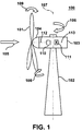
- Fig. 1 illustrates a wind turbine 100 which includes a tubular tower 102 and a machine nacelle 103 which is rotatable about a vertical axis 107.
- a rotation about the vertical axis 107 is provided by a yaw moment 106 about the axis 107.
- the wind turbine includes a rotor having a plurality of rotor blades 101 and a hub 104.
- the machine nacelle 103 which is rotatable about the vertical axis 107 is directed towards the incoming wind direction 105 by applying the yaw moment 106.
- the rotor shaft 112 of the wind turbine is driven.
- the rotor shaft 112 is connected to a gearbox 111 by means of a connection arrangement 110.
- a gearbox output shaft 113 is used to drive a means for generating electrical power, e.g. an electrical generator (not shown in Fig. 1 ). Due to the force of the incoming wind having the wind direction 105, a pitching moment 109 as shown in Fig. 1 might occur.
- a substantial part of the drive train of a wind turbine is the connection portion between the rotor shaft 112 of the wind turbine and downstream components.
- the connection between the rotor shaft 112 and downstream components is a critical issue with respect to weight, failure, maintenance interval, etc.
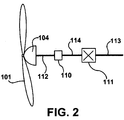
- Fig. 2 illustrates components of a drive train of a wind turbine according to a typical embodiment.
- the rotor of a wind turbine having a hub 104 and rotor blades 101 is connected to the rotor shaft 112 of the wind turbine 100.
- the drive train of the wind turbine furthermore comprises a gearbox 111 having a gearbox input shaft 114 and a gearbox output shaft 113 in order to adapt the rotational frequency of the rotor shaft 112 to a rotational frequency which is required at the gearbox output shaft 113.
- a connection arrangement 110 is provided for connecting the rotor shaft 112 and the gearbox input shaft 114.
- Fig. 3 shows the connection arrangement 110 according to a typical embodiment in more detail.
- Fig. 3 is a cross-section of the connection arrangement 110 illustrating the connection of the rotor shaft 112 and the gearbox input shaft 114.
- the rotor shaft 112 has a recessed portion arranged symmetrically to a rotation axis 115 of the rotor shaft 112.
- the gearbox input shaft 114 has a protruding portion arranged symmetrically to the rotation axis 115 of the gearbox input shaft 114. The protruding portion of the gearbox input shaft 114 engages with the recessed portion of the rotor shaft 112.
- a shrink disc 201 is provided which is adapted to fit around the periphery of the rotor shaft 112.
- the shrink disc 201 provides a frictionally engaged connection between the rotor shaft 112 and the gearbox input shaft 114.
- a first shaft connection means having the recessed portion arranged symmetrically to the axis of the rotor shaft 112 and a second shaft connection means having a protruding portion arranged symmetrically to the axis of the gearbox input shaft 114 are fixed by a fixing means which in this typical embodiment is provided as a shrink disc 201. It is noted here that the axis of the rotor shaft 112 and the axis of the gearbox input shaft 114 both coincide with the rotation axis 115 shown in Fig. 3 .
- the first shaft connection means is an end portion of the rotor shaft 112 of the wind turbine 100 and the second shaft connection means is an end portion of the gearbox input shaft 114 (gearbox input shaft) of the wind turbine 100.
- the connection arrangement 110 may be provided as a connection means between the gearbox output shaft 113 (gearbox driven shaft) of the wind turbine 100 and an output shaft of the wind turbine 100.
- the first shaft connection means may be an end portion of the gearbox driven shaft 113 of the wind turbine 100 and the second shaft connection means may be an end portion of the output shaft of the wind turbine.
- the second shaft connection means may be an end portion of the gearbox driven shaft (gearbox output shaft) 113 of the wind turbine 100 and the first shaft connection means may be an end portion of an output shaft of the wind turbine 100. It is noted here that the output shaft of the wind turbine 100 is not shown in Figs. 2 and 3 .
- the rotor shaft 112 and the gearbox input shaft 114 are connected by using a frictional engagement, when the shrink disc 201 is shrunk onto the rotor shaft 112.
- Fig. 4 is an illustration of another typical embodiment of the connection arrangement 110. As shown in Fig. 4 , all components are arranged in a cylindrical symmetry about the rotation axis 115. Fig. 4 is a cross-section of the connection arrangement 110. As before, the rotor shaft 112 is shown to have a recessed portion arranged in cylindrical symmetry about the rotation axis 115.
- the gearbox input shaft 114 has a protruding portion 207 wherein the protruding portion has a cylindrical symmetry and an outer diameter which is less than the inner diameter of the recessed portion of the rotor shaft 112.
- the space between the inner walls of the recessed portion of the rotor shaft 112 and the outer surface of the protruding portion 207 of the gearbox input shaft 114 is filled by an annular, cylindrical element 202 which is provided as an expansion element.
- the rotor shaft 112 and the gearbox input shaft 114 are connected by a frictional engagement, if the annular element 202 is expanded such that the gearbox input shaft 114 and the rotor shaft 112 are symmetrically connected.
- the second shaft connection means having the protruding portion arranged symmetrically to the rotation axis 115 of the gearbox input shaft 114 penetrates into the recessed portion of the rotor shaft 112 wherein a space is provided between the recessed portion and the protruding portion.
- the space is filled by an annular element 202 which is arranged symmetrically to the rotation axis 115 of the gearbox input shaft 114.
- the annular element fits into the space between the recessed portion and the protruding portion such that a frictionally engaged connection between the protruding portion, the annular element 202 and the recessed portion is provided.
- Fig. 5 shows a connection arrangement 100 according to another typical embodiment.
- the rotor shaft 112 has a recessed portion arranged symmetrically to the rotation axis 115.
- the gearbox input shaft 114 has also a recessed portion.
- a first recessed portion 205 corresponds to the rotor shaft 112 wherein a second recessed portion 206 corresponds to the gearbox input shaft 114.
- the gearbox input shaft 114 together with its recessed portion 206 fits into the recessed portion 205 of the rotor shaft 112.
- the rotation axis 115 is a central axis of both the rotor shaft 112 and the gearbox input shaft 114.
- a first shaft connection means having the recessed portion 205 is arranged symmetrically to the rotation axis 115 of the rotor shaft 112, wherein a second shaft connection means having the second recessed portion 206 is arranged symmetrically to the rotation axis 115 of the gearbox input shaft 114.
- the second recessed portion 206 of the second shaft connection means engages with the first recessed portion 205 of the first shaft connection means.
- a cylindrical element 203 is arranged symmetrically to the rotation axis 115 of the rotor shaft 112 and the gearbox input shaft 114, respectively.
- the cylindrical element 203 engages with the first recessed portion 205 of the first shaft connection means.
- a frictionally engaged connection is provided by an annular element 202 which is arranged between the inner surface of the second recessed portion 206 of the gearbox input shaft 114 and the outer surface of the cylindrical element 203.
- the annular element 202 may be provided as an expansion element such that an expansion of this element causes a frictionally engaged connection between the rotor shaft 112 and the gearbox input shaft 114.
- the annular element 202 which is an expansion element provides a fixing of the recessed portion at the protruding portion.
- a fixing means as a shrink disc which is arranged coaxially around the first shaft connection means (not shown in Fig. 5 ).
- recessed and protruding portions of the rotor shaft 112 and the gearbox input shaft 114 may be exchanged, respectively.
- the rotor shaft 112 is made of high-strength steal and thus can bear high stress such that it is according to a typical embodiment, that the rotor shaft 112 includes the recessed portion wherein the gearbox input shaft 114 has the protruding portion.
- bearings of the rotor shaft 112 and bearings of the gearbox input shaft 114 may have the same diameter.
- a bolt ring is provided as a connection device.
- Fig. 6 is a cross-sectional view of the connection arrangement 110 wherein details shown in Fig. 6 include a rotor shaft flange 301, a gearbox shaft flange 302 and rotor shaft bolts 303 used for a connection of the respective drive shaft, e.g. the rotor shaft 112 to the connection means 110.
- the gearbox shaft bolts 304 are provided in order to connect the connection arrangement 110 to a gearbox input shaft 114 (not shown in Fig. 6 ).
- flange connectors 305 are provided in order to connect the rotor shaft flange 301 and the gearbox shaft flange 302 to each other.
- Fig. 7 is a flowchart of a method for connecting drive shafts of a wind turbine according to yet another typical embodiment.
- a first shaft connection means having a recessed portion is provided.
- the recessed portion is arranged symmetrically to the rotation axis 115 (see Fig. 3-6 ) of the rotor shaft.
- step S2 a protruding portion of a second shaft connection means arranged symmetrically to the rotation axis 115 of the gearbox input shaft is inserted into the recessed portion of the first drive shaft connection means.
- a cylindrical element may be arranged symmetrically to the rotation axis 115 of the rotor shaft, wherein the cylindrical element engages with the first recessed portion of the first shaft connection means.
- a second shaft connection means may be provided which has a second recessed portion arranged symmetrically to the rotation axis 115 of the gearbox input shaft wherein the second recessed portion of the second shaft connection means engages with the first recessed portion of the first shaft connection means.
- the second recessed portion is pressed to watch the first recessed portion by means of an expansion of the cylindrical element.
- a bolt ring may be provided in addition to the fixing means.
- a cylindrical element may be arranged symmetrically to the axis of the rotor shaft, wherein the cylindrical element engages with the first recessed portion of the first shaft connection means.
- a second shaft connection means may be provided having a second recessed portion arranged symmetrically to the axis of the gearbox input shaft, wherein the second recessed portion of the second shaft connection means engages with the first recessed portion of the first shaft connection means.
- the second recessed portion is pressed towards the first recessed portion by means of an expansion of the cylindrical element.
Landscapes
- Engineering & Computer Science (AREA)
- General Engineering & Computer Science (AREA)
- Mechanical Engineering (AREA)
- Life Sciences & Earth Sciences (AREA)
- Sustainable Development (AREA)
- Sustainable Energy (AREA)
- Chemical & Material Sciences (AREA)
- Combustion & Propulsion (AREA)
- Wind Motors (AREA)
Claims (3)
- Aménagement de raccordement d'arbres d'éolienne (110) pour raccorder des arbres d'entraînement d'une éolienne (100), comprenant un rotor ayant un arbre de rotor (112) et un train d'engrenages (111) ayant un arbre d'entrée de train d'engrenages (114), ledit aménagement de raccordement (110) comprenant :un arbre de rotor (112) et un arbre d'entrée de train d'engrenages (114) ;un premier raccordement d'arbre comprenant une première partie évidée (205) aménagée sur l'arbre de rotor (112) symétriquement à l'axe de l'arbre de rotor (112) ;un second raccordement d'arbre comprenant une seconde partie évidée (206) aménagée dans l'arbre d'entrée de train d'engrenages (114) symétriquement à l'axe de l'arbre d'entrée de train d'engrenages (114), la seconde partie évidée (206) s'engageant sur la première partie évidée (205) ; etun aménagement de fixation comprenant un élément cylindrique (203) aménagé dans la seconde partie évidée (206) et symétrique à l'axe de l'arbre de rotor (112) ; etun élément annulaire (202) aménagé entre une surface interne de la seconde partie évidée (206) et une surface externe de l'élément cylindrique (203) et configurée pour former un raccordement à friction entre eux,dans lequel le premier raccordement d'arbre est une partie d'extrémité de l'arbre de rotor (112) et le second raccordement d'arbre est une partie d'extrémité d'un arbre d'entrée de train d'engrenage (114).
- Aménagement de raccordement d'arbres d'éolienne (110) selon la revendication 1, dans lequel au moins l'un de l'élément cylindrique (203) et de l'élément annulaire (202) est un élément d'expansion qui presse la seconde partie évidée (206) vers la première partie évidée.
- Aménagement de raccordement d'arbres d'éolienne (110) selon l'une quelconque des revendications précédentes, dans lequel la seconde partie évidée (206) pénètre dans la première partie évidée (205).
Applications Claiming Priority (1)
| Application Number | Priority Date | Filing Date | Title |
|---|---|---|---|
| US12/323,985 US7946819B2 (en) | 2008-11-26 | 2008-11-26 | Wind turbine drive shaft connection arrangement |
Publications (3)
| Publication Number | Publication Date |
|---|---|
| EP2192299A2 EP2192299A2 (fr) | 2010-06-02 |
| EP2192299A3 EP2192299A3 (fr) | 2014-01-15 |
| EP2192299B1 true EP2192299B1 (fr) | 2016-04-13 |
Family
ID=41314535
Family Applications (1)
| Application Number | Title | Priority Date | Filing Date |
|---|---|---|---|
| EP09175698.1A Not-in-force EP2192299B1 (fr) | 2008-11-26 | 2009-11-11 | Accouplement d'arbres dans une éolienne |
Country Status (4)
| Country | Link |
|---|---|
| US (1) | US7946819B2 (fr) |
| EP (1) | EP2192299B1 (fr) |
| CN (1) | CN101769227B (fr) |
| DK (1) | DK2192299T3 (fr) |
Cited By (1)
| Publication number | Priority date | Publication date | Assignee | Title |
|---|---|---|---|---|
| WO2023104412A1 (fr) * | 2021-12-10 | 2023-06-15 | Zf Friedrichshafen Ag | Transmission et générateur à arbre intermédiaire |
Families Citing this family (12)
| Publication number | Priority date | Publication date | Assignee | Title |
|---|---|---|---|---|
| ES2387439B1 (es) * | 2010-10-18 | 2013-07-26 | Gamesa Innovation & Technology, S.L. | Unión entre el eje de entrada de la multiplicadora y eje de giro del rotor. |
| US9004875B2 (en) * | 2011-03-11 | 2015-04-14 | General Electric Company | Flange and wind energy system |
| DE102011081861A1 (de) * | 2011-05-17 | 2012-11-22 | Winergy Ag | Antriebssystem für eine Windkraftanlage |
| US20120141200A1 (en) * | 2011-09-29 | 2012-06-07 | General Electric Company | One-piece coupling for a wind turbine drive shaft |
| GB201300232D0 (en) * | 2013-01-07 | 2013-02-20 | Romax Technology Ltd | Drivetrain connections |
| DE102013208568A1 (de) * | 2013-05-08 | 2014-11-13 | Lenze Drives Gmbh | Anordnung mit Hohlwelle, Antriebswelle und Spannvorrichtung |
| US9765433B2 (en) * | 2014-09-25 | 2017-09-19 | Yung-Chiu Huang | Structure of sextant rotary disk |
| KR101611378B1 (ko) | 2015-02-04 | 2016-04-12 | 주식회사 태웅 | 풍력발전용 동력전달장치 |
| US9757821B2 (en) | 2015-06-30 | 2017-09-12 | General Electric Company | System and method for in-situ resurfacing of a wind turbine main rotor shaft |
| WO2017148481A1 (fr) * | 2016-03-01 | 2017-09-08 | Vestas Wind Systems A/S | Éolienne comprenant un raccord de transmission de couple |
| US10989250B2 (en) | 2016-09-14 | 2021-04-27 | Vestas Wind Systems A/S | Coupling assembly and wind turbine comprising such assembly |
| CN116398548B (zh) * | 2023-06-07 | 2023-10-20 | 哈尔滨船舶锅炉涡轮机研究所(中国船舶集团有限公司第七0三研究所) | 一种高速超长轴及其支撑结构 |
Family Cites Families (14)
| Publication number | Priority date | Publication date | Assignee | Title |
|---|---|---|---|---|
| US2477447A (en) * | 1943-08-16 | 1949-07-26 | Thomas L Fawick | Flexible coupling |
| US3063743A (en) * | 1959-02-19 | 1962-11-13 | Skf Svenska Kullagerfab Ab | Press fitting joint |
| US4457737A (en) * | 1981-06-08 | 1984-07-03 | Beckman Instruments, Inc. | Small diameter shaft connection |
| JPH0235207A (ja) * | 1988-07-21 | 1990-02-05 | Hitachi Ltd | 回転体固定具およびそれを用いた回転体ならびにその製作方法 |
| US6461111B1 (en) * | 2000-08-25 | 2002-10-08 | Ingersoll-Rand Company | Tapered polygon coupling |
| DE10119427A1 (de) * | 2001-04-20 | 2002-10-24 | Enron Wind Gmbh | Kopplungsvorrichtung für eine Windkraftanlage |
| DE10242707B3 (de) * | 2002-09-13 | 2004-04-15 | Aerodyn Engineering Gmbh | Windenergieanlge mit konzentrischer Getriebe/Generator-Anordnung |
| DE10310639A1 (de) * | 2003-03-10 | 2004-09-23 | Volker Limbeck | Abtriebskonfiguration für Windenergieanlagen |
| JP2004339953A (ja) * | 2003-05-13 | 2004-12-02 | Kanzaki Kokyukoki Mfg Co Ltd | 風力発電装置 |
| JP4031747B2 (ja) * | 2003-09-30 | 2008-01-09 | 三菱重工業株式会社 | 風力発電用風車 |
| DK1714045T3 (da) * | 2004-02-02 | 2010-04-06 | Wilhelm Landwehr | Krympeskriveenhed og værktøj til dennes montering |
| JP2006046107A (ja) * | 2004-08-02 | 2006-02-16 | Yanmar Co Ltd | 風力発電装置 |
| DE102006027543A1 (de) * | 2006-06-14 | 2007-12-20 | Nordex Energy Gmbh | Windenergieanlage mit einem Rotor |
| WO2009080712A2 (fr) * | 2007-12-21 | 2009-07-02 | Vestas Wind Systems A/S | Chaîne dynamique pour éolienne |
-
2008
- 2008-11-26 US US12/323,985 patent/US7946819B2/en not_active Expired - Fee Related
-
2009
- 2009-11-11 EP EP09175698.1A patent/EP2192299B1/fr not_active Not-in-force
- 2009-11-11 DK DK09175698.1T patent/DK2192299T3/en active
- 2009-11-26 CN CN200910252346.XA patent/CN101769227B/zh not_active Expired - Fee Related
Cited By (1)
| Publication number | Priority date | Publication date | Assignee | Title |
|---|---|---|---|---|
| WO2023104412A1 (fr) * | 2021-12-10 | 2023-06-15 | Zf Friedrichshafen Ag | Transmission et générateur à arbre intermédiaire |
Also Published As
| Publication number | Publication date |
|---|---|
| CN101769227B (zh) | 2014-08-20 |
| DK2192299T3 (en) | 2016-06-27 |
| EP2192299A3 (fr) | 2014-01-15 |
| CN101769227A (zh) | 2010-07-07 |
| US7946819B2 (en) | 2011-05-24 |
| US20100129222A1 (en) | 2010-05-27 |
| EP2192299A2 (fr) | 2010-06-02 |
Similar Documents
| Publication | Publication Date | Title |
|---|---|---|
| EP2192299B1 (fr) | Accouplement d'arbres dans une éolienne | |
| EP2559917B1 (fr) | Axe pour système d'engrenage planétaire | |
| US8669685B2 (en) | Wind power turbine for producing electric energy | |
| EP2381092B1 (fr) | Systèmes et procédés d'assemblage d'un ensemble de verrouillage de rotor à utiliser dans une éolienne | |
| EP2416006B1 (fr) | Dispositif pour le mouvement de lacet d'une éolienne | |
| US20110143880A1 (en) | Drivetrain for generator in wind turbine | |
| EP2387132B1 (fr) | Rotor pour machine électrique tournante | |
| US20130292950A1 (en) | Wind turbine | |
| EP2574808A2 (fr) | Couplage monobloc pour arbre d'entraînement de turbine éolienne | |
| US20200088163A1 (en) | Rotor arresting device for a wind turbine and method | |
| CN105386941A (zh) | 风力涡轮机转子锁定系统 | |
| US11560877B2 (en) | Shaft-to-shaft connector for a wind turbine | |
| US20190186462A1 (en) | Nacelle and rotor for a wind turbine, and method | |
| EP2843229B1 (fr) | Système de génération d'énergie éolienne | |
| KR101345714B1 (ko) | 풍력 발전기 | |
| EP3899255B1 (fr) | Ensemble génératrice-boîte de vitesses pour une éolienne | |
| CN103670947A (zh) | 扭矩限制器、风车及风力发电装置 | |
| CN114922912A (zh) | 风力涡轮机主轴组件 | |
| US9518610B2 (en) | Load coupling and method for adjusting torsional natural frequency of power train | |
| JP2015227651A (ja) | 風力発電装置 | |
| KR20160048318A (ko) | 기어 회전 유닛과 이를 이용한 풍력 발전기 조립 방법 | |
| US20190195197A1 (en) | Rotor arresting device for a wind turbine and method | |
| JP5245271B2 (ja) | 風力発電装置 | |
| EP3771842B1 (fr) | Roulements de pale de rotor | |
| JP7042176B2 (ja) | 発電機の回転翼支持構造 |
Legal Events
| Date | Code | Title | Description |
|---|---|---|---|
| PUAI | Public reference made under article 153(3) epc to a published international application that has entered the european phase |
Free format text: ORIGINAL CODE: 0009012 |
|
| AK | Designated contracting states |
Kind code of ref document: A2 Designated state(s): AT BE BG CH CY CZ DE DK EE ES FI FR GB GR HR HU IE IS IT LI LT LU LV MC MK MT NL NO PL PT RO SE SI SK SM TR |
|
| AX | Request for extension of the european patent |
Extension state: BA RS |
|
| RIC1 | Information provided on ipc code assigned before grant |
Ipc: F16D 1/08 20060101ALN20130731BHEP Ipc: F16D 1/076 20060101ALN20130731BHEP Ipc: F16D 1/04 20060101ALN20130731BHEP Ipc: F16D 1/033 20060101ALN20130731BHEP Ipc: F03D 11/02 20060101AFI20130731BHEP Ipc: F16D 1/05 20060101ALN20130731BHEP Ipc: F16D 1/095 20060101ALN20130731BHEP |
|
| PUAL | Search report despatched |
Free format text: ORIGINAL CODE: 0009013 |
|
| AK | Designated contracting states |
Kind code of ref document: A3 Designated state(s): AT BE BG CH CY CZ DE DK EE ES FI FR GB GR HR HU IE IS IT LI LT LU LV MC MK MT NL NO PL PT RO SE SI SK SM TR |
|
| AX | Request for extension of the european patent |
Extension state: BA RS |
|
| RIC1 | Information provided on ipc code assigned before grant |
Ipc: F16D 1/08 20060101ALN20131209BHEP Ipc: F16D 1/076 20060101ALN20131209BHEP Ipc: F16D 1/033 20060101ALN20131209BHEP Ipc: F03D 11/02 20060101AFI20131209BHEP Ipc: F16D 1/04 20060101ALN20131209BHEP Ipc: F16D 1/095 20060101ALN20131209BHEP Ipc: F16D 1/05 20060101ALN20131209BHEP |
|
| 17P | Request for examination filed |
Effective date: 20140715 |
|
| RBV | Designated contracting states (corrected) |
Designated state(s): AT BE BG CH CY CZ DE DK EE ES FI FR GB GR HR HU IE IS IT LI LT LU LV MC MK MT NL NO PL PT RO SE SI SK SM TR |
|
| GRAP | Despatch of communication of intention to grant a patent |
Free format text: ORIGINAL CODE: EPIDOSNIGR1 |
|
| RIC1 | Information provided on ipc code assigned before grant |
Ipc: F16D 1/04 20060101ALN20151029BHEP Ipc: F16D 1/05 20060101ALN20151029BHEP Ipc: F03D 11/02 20060101AFI20151029BHEP Ipc: F16D 1/095 20060101ALN20151029BHEP Ipc: F16D 1/033 20060101ALN20151029BHEP Ipc: F16D 1/08 20060101ALN20151029BHEP Ipc: F16D 1/076 20060101ALN20151029BHEP |
|
| INTG | Intention to grant announced |
Effective date: 20151112 |
|
| RIC1 | Information provided on ipc code assigned before grant |
Ipc: F16D 1/05 20060101ALN20151103BHEP Ipc: F16D 1/076 20060101ALN20151103BHEP Ipc: F16D 1/095 20060101ALN20151103BHEP Ipc: F16D 1/08 20060101ALN20151103BHEP Ipc: F16D 1/04 20060101ALN20151103BHEP Ipc: F03D 11/02 20060101AFI20151103BHEP Ipc: F16D 1/033 20060101ALN20151103BHEP |
|
| RIN1 | Information on inventor provided before grant (corrected) |
Inventor name: BECKER, CHRISTIAN Inventor name: THOMASON, SCOTT Inventor name: BLOKHUIS, YVO Inventor name: HIDDING, EDWIN |
|
| GRAS | Grant fee paid |
Free format text: ORIGINAL CODE: EPIDOSNIGR3 |
|
| REG | Reference to a national code |
Ref country code: DE Ref legal event code: R079 Ref document number: 602009037693 Country of ref document: DE Free format text: PREVIOUS MAIN CLASS: F03D0011020000 Ipc: F03D0015000000 |
|
| GRAA | (expected) grant |
Free format text: ORIGINAL CODE: 0009210 |
|
| RIC1 | Information provided on ipc code assigned before grant |
Ipc: F16D 1/033 20060101ALN20160224BHEP Ipc: F16D 1/05 20060101ALN20160224BHEP Ipc: F16D 1/04 20060101ALN20160224BHEP Ipc: F03D 15/00 20160101AFI20160224BHEP Ipc: F16D 1/08 20060101ALN20160224BHEP Ipc: F16D 1/076 20060101ALN20160224BHEP Ipc: F16D 1/095 20060101ALN20160224BHEP |
|
| AK | Designated contracting states |
Kind code of ref document: B1 Designated state(s): AT BE BG CH CY CZ DE DK EE ES FI FR GB GR HR HU IE IS IT LI LT LU LV MC MK MT NL NO PL PT RO SE SI SK SM TR |
|
| REG | Reference to a national code |
Ref country code: GB Ref legal event code: FG4D |
|
| REG | Reference to a national code |
Ref country code: AT Ref legal event code: REF Ref document number: 790455 Country of ref document: AT Kind code of ref document: T Effective date: 20160415 Ref country code: CH Ref legal event code: EP |
|
| REG | Reference to a national code |
Ref country code: IE Ref legal event code: FG4D |
|
| REG | Reference to a national code |
Ref country code: DE Ref legal event code: R096 Ref document number: 602009037693 Country of ref document: DE |
|
| REG | Reference to a national code |
Ref country code: DK Ref legal event code: T3 Effective date: 20160623 |
|
| REG | Reference to a national code |
Ref country code: LT Ref legal event code: MG4D |
|
| REG | Reference to a national code |
Ref country code: AT Ref legal event code: MK05 Ref document number: 790455 Country of ref document: AT Kind code of ref document: T Effective date: 20160413 |
|
| REG | Reference to a national code |
Ref country code: NL Ref legal event code: MP Effective date: 20160413 |
|
| PG25 | Lapsed in a contracting state [announced via postgrant information from national office to epo] |
Ref country code: NL Free format text: LAPSE BECAUSE OF FAILURE TO SUBMIT A TRANSLATION OF THE DESCRIPTION OR TO PAY THE FEE WITHIN THE PRESCRIBED TIME-LIMIT Effective date: 20160413 Ref country code: PL Free format text: LAPSE BECAUSE OF FAILURE TO SUBMIT A TRANSLATION OF THE DESCRIPTION OR TO PAY THE FEE WITHIN THE PRESCRIBED TIME-LIMIT Effective date: 20160413 Ref country code: LT Free format text: LAPSE BECAUSE OF FAILURE TO SUBMIT A TRANSLATION OF THE DESCRIPTION OR TO PAY THE FEE WITHIN THE PRESCRIBED TIME-LIMIT Effective date: 20160413 Ref country code: NO Free format text: LAPSE BECAUSE OF FAILURE TO SUBMIT A TRANSLATION OF THE DESCRIPTION OR TO PAY THE FEE WITHIN THE PRESCRIBED TIME-LIMIT Effective date: 20160713 Ref country code: FI Free format text: LAPSE BECAUSE OF FAILURE TO SUBMIT A TRANSLATION OF THE DESCRIPTION OR TO PAY THE FEE WITHIN THE PRESCRIBED TIME-LIMIT Effective date: 20160413 |
|
| PG25 | Lapsed in a contracting state [announced via postgrant information from national office to epo] |
Ref country code: AT Free format text: LAPSE BECAUSE OF FAILURE TO SUBMIT A TRANSLATION OF THE DESCRIPTION OR TO PAY THE FEE WITHIN THE PRESCRIBED TIME-LIMIT Effective date: 20160413 Ref country code: SE Free format text: LAPSE BECAUSE OF FAILURE TO SUBMIT A TRANSLATION OF THE DESCRIPTION OR TO PAY THE FEE WITHIN THE PRESCRIBED TIME-LIMIT Effective date: 20160413 Ref country code: GR Free format text: LAPSE BECAUSE OF FAILURE TO SUBMIT A TRANSLATION OF THE DESCRIPTION OR TO PAY THE FEE WITHIN THE PRESCRIBED TIME-LIMIT Effective date: 20160714 Ref country code: PT Free format text: LAPSE BECAUSE OF FAILURE TO SUBMIT A TRANSLATION OF THE DESCRIPTION OR TO PAY THE FEE WITHIN THE PRESCRIBED TIME-LIMIT Effective date: 20160816 Ref country code: LV Free format text: LAPSE BECAUSE OF FAILURE TO SUBMIT A TRANSLATION OF THE DESCRIPTION OR TO PAY THE FEE WITHIN THE PRESCRIBED TIME-LIMIT Effective date: 20160413 Ref country code: ES Free format text: LAPSE BECAUSE OF FAILURE TO SUBMIT A TRANSLATION OF THE DESCRIPTION OR TO PAY THE FEE WITHIN THE PRESCRIBED TIME-LIMIT Effective date: 20160413 Ref country code: HR Free format text: LAPSE BECAUSE OF FAILURE TO SUBMIT A TRANSLATION OF THE DESCRIPTION OR TO PAY THE FEE WITHIN THE PRESCRIBED TIME-LIMIT Effective date: 20160413 |
|
| PG25 | Lapsed in a contracting state [announced via postgrant information from national office to epo] |
Ref country code: BE Free format text: LAPSE BECAUSE OF FAILURE TO SUBMIT A TRANSLATION OF THE DESCRIPTION OR TO PAY THE FEE WITHIN THE PRESCRIBED TIME-LIMIT Effective date: 20160413 Ref country code: IT Free format text: LAPSE BECAUSE OF FAILURE TO SUBMIT A TRANSLATION OF THE DESCRIPTION OR TO PAY THE FEE WITHIN THE PRESCRIBED TIME-LIMIT Effective date: 20160413 |
|
| REG | Reference to a national code |
Ref country code: DE Ref legal event code: R097 Ref document number: 602009037693 Country of ref document: DE |
|
| PG25 | Lapsed in a contracting state [announced via postgrant information from national office to epo] |
Ref country code: EE Free format text: LAPSE BECAUSE OF FAILURE TO SUBMIT A TRANSLATION OF THE DESCRIPTION OR TO PAY THE FEE WITHIN THE PRESCRIBED TIME-LIMIT Effective date: 20160413 Ref country code: CZ Free format text: LAPSE BECAUSE OF FAILURE TO SUBMIT A TRANSLATION OF THE DESCRIPTION OR TO PAY THE FEE WITHIN THE PRESCRIBED TIME-LIMIT Effective date: 20160413 Ref country code: RO Free format text: LAPSE BECAUSE OF FAILURE TO SUBMIT A TRANSLATION OF THE DESCRIPTION OR TO PAY THE FEE WITHIN THE PRESCRIBED TIME-LIMIT Effective date: 20160413 Ref country code: SK Free format text: LAPSE BECAUSE OF FAILURE TO SUBMIT A TRANSLATION OF THE DESCRIPTION OR TO PAY THE FEE WITHIN THE PRESCRIBED TIME-LIMIT Effective date: 20160413 |
|
| PLBE | No opposition filed within time limit |
Free format text: ORIGINAL CODE: 0009261 |
|
| STAA | Information on the status of an ep patent application or granted ep patent |
Free format text: STATUS: NO OPPOSITION FILED WITHIN TIME LIMIT |
|
| PG25 | Lapsed in a contracting state [announced via postgrant information from national office to epo] |
Ref country code: SM Free format text: LAPSE BECAUSE OF FAILURE TO SUBMIT A TRANSLATION OF THE DESCRIPTION OR TO PAY THE FEE WITHIN THE PRESCRIBED TIME-LIMIT Effective date: 20160413 |
|
| 26N | No opposition filed |
Effective date: 20170116 |
|
| PG25 | Lapsed in a contracting state [announced via postgrant information from national office to epo] |
Ref country code: SI Free format text: LAPSE BECAUSE OF FAILURE TO SUBMIT A TRANSLATION OF THE DESCRIPTION OR TO PAY THE FEE WITHIN THE PRESCRIBED TIME-LIMIT Effective date: 20160413 |
|
| REG | Reference to a national code |
Ref country code: CH Ref legal event code: PL |
|
| GBPC | Gb: european patent ceased through non-payment of renewal fee |
Effective date: 20161111 |
|
| PG25 | Lapsed in a contracting state [announced via postgrant information from national office to epo] |
Ref country code: CH Free format text: LAPSE BECAUSE OF NON-PAYMENT OF DUE FEES Effective date: 20161130 Ref country code: LI Free format text: LAPSE BECAUSE OF NON-PAYMENT OF DUE FEES Effective date: 20161130 |
|
| REG | Reference to a national code |
Ref country code: IE Ref legal event code: MM4A |
|
| REG | Reference to a national code |
Ref country code: FR Ref legal event code: ST Effective date: 20170731 |
|
| PG25 | Lapsed in a contracting state [announced via postgrant information from national office to epo] |
Ref country code: LU Free format text: LAPSE BECAUSE OF NON-PAYMENT OF DUE FEES Effective date: 20161130 |
|
| PG25 | Lapsed in a contracting state [announced via postgrant information from national office to epo] |
Ref country code: FR Free format text: LAPSE BECAUSE OF NON-PAYMENT OF DUE FEES Effective date: 20161130 |
|
| PG25 | Lapsed in a contracting state [announced via postgrant information from national office to epo] |
Ref country code: GB Free format text: LAPSE BECAUSE OF NON-PAYMENT OF DUE FEES Effective date: 20161111 Ref country code: IE Free format text: LAPSE BECAUSE OF NON-PAYMENT OF DUE FEES Effective date: 20161111 |
|
| PGFP | Annual fee paid to national office [announced via postgrant information from national office to epo] |
Ref country code: DK Payment date: 20171127 Year of fee payment: 9 Ref country code: DE Payment date: 20171129 Year of fee payment: 9 |
|
| PG25 | Lapsed in a contracting state [announced via postgrant information from national office to epo] |
Ref country code: HU Free format text: LAPSE BECAUSE OF FAILURE TO SUBMIT A TRANSLATION OF THE DESCRIPTION OR TO PAY THE FEE WITHIN THE PRESCRIBED TIME-LIMIT; INVALID AB INITIO Effective date: 20091111 Ref country code: CY Free format text: LAPSE BECAUSE OF FAILURE TO SUBMIT A TRANSLATION OF THE DESCRIPTION OR TO PAY THE FEE WITHIN THE PRESCRIBED TIME-LIMIT Effective date: 20160413 |
|
| PG25 | Lapsed in a contracting state [announced via postgrant information from national office to epo] |
Ref country code: IS Free format text: LAPSE BECAUSE OF FAILURE TO SUBMIT A TRANSLATION OF THE DESCRIPTION OR TO PAY THE FEE WITHIN THE PRESCRIBED TIME-LIMIT Effective date: 20160413 Ref country code: MK Free format text: LAPSE BECAUSE OF FAILURE TO SUBMIT A TRANSLATION OF THE DESCRIPTION OR TO PAY THE FEE WITHIN THE PRESCRIBED TIME-LIMIT Effective date: 20160413 Ref country code: TR Free format text: LAPSE BECAUSE OF FAILURE TO SUBMIT A TRANSLATION OF THE DESCRIPTION OR TO PAY THE FEE WITHIN THE PRESCRIBED TIME-LIMIT Effective date: 20160413 Ref country code: MC Free format text: LAPSE BECAUSE OF FAILURE TO SUBMIT A TRANSLATION OF THE DESCRIPTION OR TO PAY THE FEE WITHIN THE PRESCRIBED TIME-LIMIT Effective date: 20160413 |
|
| PG25 | Lapsed in a contracting state [announced via postgrant information from national office to epo] |
Ref country code: BG Free format text: LAPSE BECAUSE OF FAILURE TO SUBMIT A TRANSLATION OF THE DESCRIPTION OR TO PAY THE FEE WITHIN THE PRESCRIBED TIME-LIMIT Effective date: 20160413 |
|
| PG25 | Lapsed in a contracting state [announced via postgrant information from national office to epo] |
Ref country code: MT Free format text: LAPSE BECAUSE OF NON-PAYMENT OF DUE FEES Effective date: 20161111 |
|
| REG | Reference to a national code |
Ref country code: DE Ref legal event code: R119 Ref document number: 602009037693 Country of ref document: DE |
|
| REG | Reference to a national code |
Ref country code: DK Ref legal event code: EBP Effective date: 20181130 |
|
| PG25 | Lapsed in a contracting state [announced via postgrant information from national office to epo] |
Ref country code: DE Free format text: LAPSE BECAUSE OF NON-PAYMENT OF DUE FEES Effective date: 20190601 Ref country code: DK Free format text: LAPSE BECAUSE OF NON-PAYMENT OF DUE FEES Effective date: 20181130 |