EP2192209B1 - Device for cleaning oxidized or corroded components in the presence of a halogenous gas mixture - Google Patents
Device for cleaning oxidized or corroded components in the presence of a halogenous gas mixture Download PDFInfo
- Publication number
- EP2192209B1 EP2192209B1 EP09175543.9A EP09175543A EP2192209B1 EP 2192209 B1 EP2192209 B1 EP 2192209B1 EP 09175543 A EP09175543 A EP 09175543A EP 2192209 B1 EP2192209 B1 EP 2192209B1
- Authority
- EP
- European Patent Office
- Prior art keywords
- gas
- cleaning
- components
- central pipe
- along
- Prior art date
- Legal status (The legal status is an assumption and is not a legal conclusion. Google has not performed a legal analysis and makes no representation as to the accuracy of the status listed.)
- Active
Links
Images

Classifications
-
- C—CHEMISTRY; METALLURGY
- C23—COATING METALLIC MATERIAL; COATING MATERIAL WITH METALLIC MATERIAL; CHEMICAL SURFACE TREATMENT; DIFFUSION TREATMENT OF METALLIC MATERIAL; COATING BY VACUUM EVAPORATION, BY SPUTTERING, BY ION IMPLANTATION OR BY CHEMICAL VAPOUR DEPOSITION, IN GENERAL; INHIBITING CORROSION OF METALLIC MATERIAL OR INCRUSTATION IN GENERAL
- C23G—CLEANING OR DE-GREASING OF METALLIC MATERIAL BY CHEMICAL METHODS OTHER THAN ELECTROLYSIS
- C23G5/00—Cleaning or de-greasing metallic material by other methods; Apparatus for cleaning or de-greasing metallic material with organic solvents
-
- F—MECHANICAL ENGINEERING; LIGHTING; HEATING; WEAPONS; BLASTING
- F01—MACHINES OR ENGINES IN GENERAL; ENGINE PLANTS IN GENERAL; STEAM ENGINES
- F01D—NON-POSITIVE DISPLACEMENT MACHINES OR ENGINES, e.g. STEAM TURBINES
- F01D25/00—Component parts, details, or accessories, not provided for in, or of interest apart from, other groups
- F01D25/002—Cleaning of turbomachines
Definitions
- the invention relates to a device for cleaning oxidized or corroded components in the presence of a halogen-containing gas mixture, with a purification reactor, in the middle or immediately opens a feed line which is connected via a flow control device with a gas-storing the halogen-containing gas mixture gas reservoir.
- these components can be turbine components acted upon by hot gases, in particular gas turbine blades.
- Turbine components for engines or stationary gas turbine plants which are exposed to medium or direct hot gas flows, such as guide or moving blades, heat accumulation segments or similar components or groups of components delimiting the hot gas channel are subject to operational material degradation, which often leads to cracks and, associated therewith, mechanical weakening of the respective components , Due to the prevailing in the hot gas channels high temperature and pressure loads, which are exposed to the corresponding mostly made of nickel-based components, divide with increasing operating time by external and internal oxidation complex chemically and thermally stable oxides on the component surfaces, within the forming crack openings and in near-surface areas within the base material.
- the aim is to transfer the claimed and partially damaged components with a special process chain in a state that largely corresponds to the state of a newly manufactured, comparable component.
- one of the steps is to thoroughly clean the component to be reworked, i. to eliminate the deposited on the component surface and in the cracks formed complex oxide layer, without damaging the material of the component itself.
- reaction chamber in which a halogen-containing gas mixture is introduced for the purpose of component cleaning, be temporarily rinsed with a non-halogen-containing gas during the cleaning.
- the US 6,536,135 B2 describes an FIC process in which an improved O-xidalism by varying the partial pressures of the cleaning gas mixture is made by the consisting of hydrogen fluoride (HF) and hydrogen (H 2 ) cleaning gas mixture is added as another component carbon.
- the carbon is added in the form of various compounds which form a carbonaceous gas during the process.
- a typical purification reactor which provides a cylindrical housing which is gas-tight from above and can be fitted in an open state from above with components to be cleaned.
- the components to be cleaned are housed on vertically stacked storage levels, so-called trays, which are attached to a centrally located in the cleaning reactor central tube through which a carbon-enriched hydrogen fluoride gas mixture is fed to the purification reactor.
- the reactor head penetrating the gas-tight central tube extends vertically within the cleaning reactor down into the region of the so-called reactor sump, in which the central tube is a substantially over the entire Cross-section of the cleaning reactor extending gas distributor structure provides with outlet openings through which the halogen-containing cleaning gas mixture is fed from bottom to top in the purification reactor.
- the cleaning gas mixture flows through the entire reactor volume from the reactor sump in the direction of the reactor head, at which a corresponding Gausauslassö réelle is provided.
- the Applicant also has many years of practical experience in the field of cleaning operationally contaminated, corroded, oxidized and degraded gas turbine components of the type discussed above, in particular using FIC purification techniques and the cleaning equipment required therefor.
- a relevant purification reactor which is fed via a central tube with a cleaning gas mixture containing hydrogen fluoride and hydrogen in varying ratios, it has been shown that significant disturbances in the cleaning process caused by volume fluctuations in the supply of the cleaning gas in the purification reactor, which may occasionally lead to the termination of the entire cleaning process if certain levels are exceeded.
- the invention is based on the object, a device for the purification of oxidized or corroded components, in particular of hot gases exposed gas turbine components, in the presence of a halogen-containing gas, with a usually kesselelförmig formed purification reactor, in the middle or directly opens a feed line, which via a flow control device with a reservoir storing the halogen-containing gas, in such a way that, on the one hand, care is taken to completely eliminate the problems associated with an insufficient or fluctuating cleaning gas feed into the purification reactor.
- the solution according to the device according to the features of the preamble of claim 1 is characterized in that the flow control device in sequence along the flow direction of the feed line flowing through the halogen-containing gas provides a gas flow control valve, a heat exchanger unit and a gas flow measuring unit.
- the device according to the invention is based on the finding that form condensations along the feed line for the supply of the halogen-containing gas, which occur in particular in the region of throttle points. Such condensations lead to erroneous values in the range of the gas flow control and can lead to total failure of the quantity measurement.
- the halogen-containing gas is preferably stored in pressure bottles. Under the storage conditions, it is liquid. By raising the temperature, the liquid becomes evaporates, and it adjusts the temperature-dependent vapor pressure of the substance. Before the gas control thus prevail overpressure conditions.
- the pressure within the purification reactor is typically at the pressure level of 50 Torr to 780 Torr. Therefore, it requires along the feed line at least one pressure-reducing throttle stage. In this case, the above condensation problem occurs.
- the device according to the invention contains as throttle point along the feed line at least one flow control device which provides a gas-expanding gas flow control valve.
- a heating unit which preferably has a gas heater, is provided immediately downstream of the gas flow control valve, whereby the temperature level in this line region is raised above the condensation level of the halogen-containing gas, preferably HF gas.
- the gas flow measuring unit Downstream along the feed line to the heat exchanger is immediately followed by the gas flow measuring unit.
- a heating of the heat exchanger using a variety of heating techniques is possible.
- the use of electrical heating has proved to be particularly advantageous.
- appropriately heated heat transfer medium or other heating media the line area downstream of the gas flow control valve.
- the heat exchanger unit is to be designed or selected with respect to its heat output such that a temperature level between 22 ° C and 75 ° C, preferably 40 ° C to 50 ° C and particularly preferably 44 ° C to 46 ° C can be adjusted.
- a shut-off valve is provided upstream and downstream of the flow control device in the feed line, which in each case can be actuated automatically or manually in the event of a possible failure of the flow control device.
- a bypass line to the flow control device along the feed line is provided, along which a control valve, preferably a manual control valve, is introduced.
- a device with the features according to the preamble of the present claim 4 which is medium or direct with the at least one feed line connected central tube, which extends from the reactor head to the reactor sump within the purification reactor and is connected in the region of the reactor sump with a radially extending to the central tube, first distributor structure having outlet openings for the halogen-containing gas, according to solution, characterized in that the first distributor structure a Supporting plane for the components to be cleaned, and a second distributor structure is provided which is spaced from the first distributor structure attached to the central tube. At the same time, the first distributor structure forms a supporting plane extending radially to the central tube for the components to be cleaned, wherein the distributor structures have outlet openings for the halogen-containing gas, at least in the direction of the components resting thereon.
- the novel gas distribution concept provides for the arrangement of preferably a plurality of so-called distributor structures arranged one above the other along the central tube before, which are either self-supporting attached to the central tube or combined with suitably formed support structures along the central tube.
- the novel decentralized gas distribution in the purifying reactor serves to distribute the process gas as optimally as possible by adding and removing the purge gas to each individual component under largely identical conditions. Due to an individual cleaning gas feed in each individual support level for the components to be cleaned, it is ensured that each individual component is directly and suitably supplied with cleaning gas.
- the number and arrangement of the provided in the respective distribution structure outlet openings can be chosen basically arbitrary, but preferably taking into account the shape, size and arrangement of the components to be cleaned.
- the distributor structures which are each mounted along the central tube at an axial distance and which, depending on the design, can be integrated into stable support structures or formed in the form of intrinsically stable plate or tube constructions, are made of a material which is resistant to the process conditions prevailing in the purification reactor for this IN600 (Inconel 600).
- the cleaning reactor is to be equipped with a suitable number of distribution structures to be arranged along the central pipe, onto which the components to be cleaned are to be applied.
- the individual distributor structures can be introduced in a modular manner and taking into account the cleaning task described above.
- the distributor structures have a central sleeve with a sleeve opening for receiving the central tube.
- the individual distributor structures can be positioned and fixed along the central tube.
- a corresponding number of cylindrical spacer sleeves are provided, which are slid longitudinally over the central tube as spacers and fix the sleeves provided with the distributor structures spaced apart from each other along the central tube.
- the distributor structures extending radially from the sleeve can be formed or implemented in different ways. Plate-shaped or grid-shaped or tubular formations for the distributor structure have proven to be particularly advantageous.
- at least one of the central tube radially extending stub is provided, spaced from the radial to the central tube at least one central tube annularly circulating ring line is mounted.
- the respective outlet openings are borne along the at least one stub line and the at least one ring line borne in each case oriented upwards, so that the resting on the distributor structure components are acted upon directly by the emerging from the outlet openings cleaning gas.
- the cuffs described above, with which the distributor structure is connected have gas openings oriented radially relative to the central tube, through which the cleaning gas radially emerging from the central tube via corresponding gas outlet openings can reach the respective distributor structures. Details of this can be found in the further description with reference to the figures.
- the respective distributor structures are disc-shaped and each have an upper and a lower disc plate on, which include a gap, which is also surrounded gas-tight by a disk rim which connects the two disc plates at its peripheral edge in a fluid-tight manner.
- the disk volume limited in this way is fed via an opening facing the central pipe with the halogen-containing cleaning gas, which can escape from the disk volume at least via outlet openings introduced in the upper disk plate.
- the number, arrangement or orientation and the diameter of the individual outlet openings are basically variably adjustable over a wide range. Thus, for example, between 100 and 10000 holes or outlet openings are provided per diameter structure, each with diameters between 0.1 mm to 5 mm.
- outlet openings Depending on the dimensions of the purification reactor and the components to be cleaned within the purification reactor, in practice preferred dimensions for the outlet openings have been provided, which provide 1000 to 5000 outlet openings per distribution structure, each with diameters between 0.5 and 2.5 mm.
- outlet openings For the purpose of an improved, matched to the shape and size of each component to be cleaned flow of cleaning gas, it is appropriate to arrange the outlet openings with respect to the generally circular support level sectorally suitable or distribute, for example in the form of radial lines or radially and in the circumferential direction ordered field pattern in which the outlet openings are arranged in groups summarized.
- the outlet openings in the form of conventional bores, it is particularly advantageous to tailor the outlet openings so that the individual gas streams emerging from the outlet openings strike the respective component to be cleaned at an optimized flow rate and with a predeterminable outflow direction.
- the gas outlet direction influencing flow outlet elements which can be formed in a suitable manner already during the production of the outlet openings, for example in the context of shaping punching processes.
- the distributor structures not only provide outlet openings for the cleaning gas at the upper side facing the support plane in order to apply cleaning gas to the components resting on the respective distributor structures, but moreover corresponding outlet openings are provided on the opposite lower side in order to provide a cleaning gas Align part of the cleaning gas exiting through the distributor structure with those components that rest on the support level directly below.
- Such optional additional components can preferably be installed between the respective distributor structures or directly on the components to be cleaned, in order to apply certain areas of components to the cleaning gas in a particular manner or to shield certain areas from the cleaning gas in order to make direct contact with them to avoid the cleaning gas.
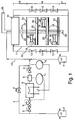
- FIG. 1 illustrates a schematic structure of a purification reactor (right half of the figure), which is supplied via a cleaning gas line system (left half of the figure) with a cleaning gas mixture.
- the cleaning reactor has a substantially cylinder-shaped or barrel-shaped reactor housing 11, which is closed gas-tight on its upper side with a reactor cover 14.
- the reactor housing 11 is surrounded by a heating jacket 12 in which heaters 13 provide a cleaning process temperature inside the purification reactor of up to 1200 ° C.
- a central tube 23 is centrally provided which penetrates the reactor cover 14 gas-tight to the outside, and into which via a feed line 10 cleaning gas is fed.
- a reactor outlet 24 is provided within the purification reactor, is brought via the spent cleaning gas via a corresponding exhaust pipe 25 to the outside for further supply and disposal.
- two gas reservoirs 1,1 ' provided, namely a gas reservoir for the provision of hydrogen fluoride (HF) and a gas reservoir for the provision of hydrogen gas (H 2 ). Both types of gas are to be mixed in a suitable manner before being fed into the feed line 10 with a predetermined mixing ratio.
- a flow control device connects, which consists of a gas flow control valve 5, a heat exchanger unit 9, preferably in the form of a gas heater and a gas flow measuring unit 6 is.
- the immediately downstream of the gas flow control valve 5 subsequent heat exchanger unit 9 ensures a significant increase in temperature on the condensation temperature of the HF gas, so that a non-affected by any condensation processes HF gas supply can be ensured using the flow control device.
- a gas temperature control circuit 8 For monitoring and control of the heat exchanger unit 9 is a gas temperature control circuit 8.
- a suitable gas flow control loop 7 is provided for the controlled implementation of the gas flow measurement.
- a bypass line 2 is additionally provided, in which a shut-off valve, preferably a manual control valve 4, is mounted.
- the bypass line 2 is used in the case in which the flow control device, consisting of the gas flow control valve 5 of the heat exchanger unit 9 and the gas flow measuring unit 6 upstream and downstream with the help of two block valves 3 is separated from the gas supply.
- the used block valves 3 may preferably be in the form of valves, taps or slides, which can be driven both manually and automatically.
- the provided in the bypass line 2 manual control valve is preferably designed as a needle passage valve, which allows a very finely metered adjustment of the HF gas flow.
- the HF cleaning gas mixture fed into the central tube 23 along the feed line 10 exits within the process chamber 16 of the purification reactor via distributor structures 20 mounted at different levels along the central tube 23 and on which the components 26 to be cleaned each rest.
- the distributor structures 20 provided in the process space 16 are designed separately for support structures 19 likewise mounted radially on the central tube 23 and on which the distributor structures 20 are supported.
- the cleaning gas passes through the central tube 23 in each case in the distributor structures 20, of which it is directed directly to the components 26 to be cleaned exit.
- Additional provided within the process chamber 16 Gasleitbleche 27, 28 and 29 provide for an individual flow of the individual components to be cleaned 26 with cleaning gas.
- the lowest distribution structure 20 which is integrated in a stable bottom support 21, which is preferably fixedly connected to the central tube 23.
- a heat shield 22 is attached to the central tube 23 in the upper region within the purification reactor.
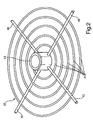
- FIG. 2 is a perspective view of a preferred embodiment of a distribution structure 20 is shown.
- the distributor structure 20 has a central sleeve 43, which can be pushed forcibly guided over the central tube, not shown. Only the completeness it should be noted that instead of the sleeve, the manifold structure 20 may also be connected directly to the central tube 23, in this case, the component 43 corresponds to the central tube.
- stub lines 40 Radially starting from the sleeve 43, four stub lines 40 adjoin these, to which concentric ring lines 41 are respectively connected.
- the stub lines 40 and ring lines 41 form a communicating piping system, which is supplied from the central tube 23, not shown, with cleaning gas.
- the sleeve 43 openings (not shown) via which the cleaning gas provided by the central tube 23 can be fed into the distribution system.
- the distribution structure 20 is eigentragschreib and robust and firmly enough connected to the sleeve 43 to accommodate both the weight of the manifold structure 20 and the weight of applied to the manifold structure 20 to be cleaned components 26.
- the outlet openings provided along the stub lines 40 and ring lines 41, via which the cleaning gas exits in the direction of the components resting on the distributor structure 20, are shown.
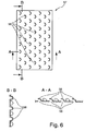
- FIG. 3 strongly schematically illustrates an alternative embodiment of a distributor structure, which is plate-shaped.
- the manifold structure in this case has an upper 50 and lower 51 disc plate, both plates 50 and 51 are bounded by a circumferential disc rim 52 and include an internal volume.
- the distributor structure is connected to a mechanically stable support structure 54.
- the upper disk plate 50 has sectors, characterized by boundary lines 55, which extend in the illustrated case along each radially. The individual sectors can be exchanged in order to adapt the reactor as variably as possible to different component types.
- the plate-shaped distributor structure is penetrated by the central tube 23, to which the distributor structure 20 is firmly attached.
- the manifold structure is connected to a cuff described above, which is threaded over the central tube 23.
- FIG. 4 is a perspective cross-sectional view represented by a plate-shaped distribution structure.
- the upper and lower disc plates 50, 51 are directly attached to the central central tube 23.
- 23 may be a cuff.
- cleaning gas supplied through the central tube or sleeve 23 passes into the intermediate space between the upper and lower disc plates 50, 51.
- suitable outlet openings 56 which are incorporated in the upper disc plate 50, the cleaning gas finally exits into the process space.
- the outlet openings 56 are preferably arranged in consideration of the components to be cleaned, which are to be applied to the upper disc plate 50, respectively. This in FIG. 4 illustrated embodiment provides sectoral field-like pattern order for the outlet openings 56.
- FIG. 4 illustrated embodiment provides sectoral field-like pattern order for the outlet openings 56.
- FIG. 5 the plan view of a segment surface of the upper disc plate 50 is shown, in which a plurality of fields 57 are arranged, each composed of a plurality of individual outlet openings 56.
- the arrangement as well as the number of outlet openings 56 within the individual fields 57 can each be identical or different, preferably be selected depending on the respective components to be cleaned.
- FIG. 6 schematically shows an enlarged view of a field 57, in which a plurality of individual outlet openings 56 is provided. Based on the sectional views AA and BB, the contours of the individual outlet openings are visible. In particular, it can be seen from the sectional representation AA that each individual outlet opening 56 is covered by a flow guide element 58, whereby the outlet flow can be spatially directed onto the respective component.
- the optimized control and gas distribution helps to significantly reduce the amount of HF gas to be injected for cleaning purposes. On the one hand, this reduces the risk of damage to the individual components while simultaneously improving the cleaning effect. On the other hand, this can be safely avoided over-etched surface areas on the components. In addition, the entire system is less burdened by the chemically highly reactive cleaning gas, so that the life and use of such systems and their components can be significantly extended.
- the measures of the invention help to reduce resources such as the process gases, energy and beyond required resources significantly.
- the reduction of the cleaning gas automatically leads to the reduction of the resulting discharge material flows to be disposed of and thus to the significant reduction of the waste. Overall, the operating costs of such systems can be significantly reduced with the solution according to the concept. This also contributes to a higher loading density of the reactor, as well as a reduction of the process times.
Description
Die Erfindung bezieht sich auf eine Vorrichtung zur Reinigung oxidierter oder korrodierter Bauteile in Gegenwart eines halogenhaltigen Gasgemisches, mit einem Reinigungsreaktor, in den mittel- oder unmittelbar eine Speiseleitung mündet, die über eine Durchflussregeleinrichtung mit einem das halogenhaltige Gasgemisch bevorratenden Gasreservoir verbunden ist. Insbesondere kann es sich bei diesen Bauteilen um von Heissgasen beaufschlagte Turbinenkomponenten, insbesondere Gasturbinenschaufeln, handeln.The invention relates to a device for cleaning oxidized or corroded components in the presence of a halogen-containing gas mixture, with a purification reactor, in the middle or immediately opens a feed line which is connected via a flow control device with a gas-storing the halogen-containing gas mixture gas reservoir. In particular, these components can be turbine components acted upon by hot gases, in particular gas turbine blades.
Turbinenkomponenten für Triebwerke oder stationäre Gasturbinenanlagen, die mittel- oder unmittelbar Heissgasströmungen ausgesetzt sind, wie beispielsweise Leit- oder Laufschaufeln, Wärmestausegmente oder ähnliche den Heissgaskanal begrenzende Bauteile oder Bauteilgruppen unterliegen betriebsbedingten Materialdegradationen, die häufig zu Rissen und damit verbunden zur mechanischen Schwächung der jeweiligen Komponenten führen. Aufgrund der in den Heissgaskanälen vorherrschenden hohen Temperatur- und Druckbelastungen, denen die entsprechenden zumeist aus Nickelbasiswerkstoffen gefertigten Bauteile ausgesetzt sind, scheiden sich mit zunehmender Betriebsdauer durch äussere und innere Oxidation komplexe chemisch und thermisch stabile Oxide an den Bauteiloberflächen, innerhalb der sich ausbildenden Rissöffnungen sowie in oberflächennahen Bereichen innerhalb des Basismaterials ab.Turbine components for engines or stationary gas turbine plants, which are exposed to medium or direct hot gas flows, such as guide or moving blades, heat accumulation segments or similar components or groups of components delimiting the hot gas channel are subject to operational material degradation, which often leads to cracks and, associated therewith, mechanical weakening of the respective components , Due to the prevailing in the hot gas channels high temperature and pressure loads, which are exposed to the corresponding mostly made of nickel-based components, divide with increasing operating time by external and internal oxidation complex chemically and thermally stable oxides on the component surfaces, within the forming crack openings and in near-surface areas within the base material.
Ziel ist es, die derart beanspruchten und zum Teil beschädigten Bauteile mit einer speziellen Prozesskette in einen Zustand überführen, der weitgehend dem Zustand eines neu gefertigten, vergleichbaren Bauteils entspricht. Hierbei ist einer der Schritte, das zu überarbeitende Bauteil sorgfältig zu reinigen, d.h. die an der Bauteiloberfläche sowie in den sich ausgebildeten Rissen abgeschiedene komplexe Oxidschicht zu beseitigen, ohne dabei das Material des Bauteils selbst zu schädigen.The aim is to transfer the claimed and partially damaged components with a special process chain in a state that largely corresponds to the state of a newly manufactured, comparable component. Here, one of the steps is to thoroughly clean the component to be reworked, i. to eliminate the deposited on the component surface and in the cracks formed complex oxide layer, without damaging the material of the component itself.
In der
Aus der
Weitgehend allen Bestrebungen zur Verbesserung derartiger FIC-Verfahren ist die Aufgabe gemeinsam, Oxidschichtanteile, die sich insbesondere in rissbedingten Spalt- oder Grabenstrukturen abgeschieden haben, vollständig zu beseitigen, zumal bereits geringste Restanteile oxidierter oder korrodierter Oberflächen nachhaltige Auswirkungen auf anschließende Reparaturmaßnahmen haben. Typischerweise erfolgt zu Zwecken der Rissheilung an den jeweils gereinigten Bauteilen ein Löt- oder Schweißvorgang derart, dass über einem gereinigten Riss eine Reparaturlegierung in Pulverform angehäuft wird, die in Gegenwart von Vakuum und unter Hitzeeinwirkung zum Schmelzen und schließlich zum Fließen in den spaltförmigen Riss gebracht wird. Hierbei bildet sich eine Benetzung der Risswand mit der verflüssigten Reparaturlegierung aus. Es liegt auf der Hand, dass entsprechende Benetzungen an einer mit einer Oxidschicht behafteten Bauteiloberfläche nicht oder in einem weit geringeren Maß erfolgen, wodurch letztlich Reparaturschwachstellen entstehen, die es zu vermeiden gilt.Largely all efforts to improve such FIC methods, the task is common to completely eliminate oxide layer portions, which have deposited in particular crack-related gap or trench structures, especially since even the smallest residual shares of oxidized or corroded surfaces have lasting effects on subsequent repair measures. Typically, for purposes of crack healing on the respective cleaned components, a soldering or welding operation is performed such that over a cleaned crack a repair alloy in powder form is accumulated, which in the presence of vacuum and heat causes melting and finally flow into the gap crack , This forms a wetting of the crack wall with the liquefied repair alloy. It is obvious that corresponding wetting on a component surface subject to an oxide layer is not or to a much lesser extent, which ultimately creates repair vulnerabilities that need to be avoided.
In der vorstehend zitierten
In der
Die
Ferner ist der Druckschrift ein typischer Reinigungsreaktor zu entnehmen, der ein zylinderförmiges Gehäuse vorsieht, das von oben gasdicht verschließbar ist und in einem geöffneten Zustand von oben mit zu reinigenden Bauteilen bestückt werden kann. Die zu reinigenden Bauteile werden auf vertikal übereinander vorgesehenen Ablageebenen, sogenannten Böden, untergebracht, die an einem im Reinigungsreaktor mittig angeordneten Zentralrohr befestigt sind, durch das ein kohlenstoffangereichertes Fluorwasserstoff-Gasgemisch dem Reinigungsreaktor zugeführt wird. Das den Reaktorkopf gasdicht durchragende Zentralrohr erstreckt sich vertikal innerhalb des Reinigungsreaktors nach unten in den Bereich des sogenannten Reaktorsumpfes, in dem das Zentralrohr eine sich im wesentlichen über den gesamten Querschnitt des Reinigungsreaktors erstreckende Gasverteilerstruktur mit Austrittsöffnungen vorsieht, über die das halogenhaltige Reinigungsgasgemisch von unten nach oben aufsteigend in den Reinigungsreaktor eingespeist wird. Das Reinigungsgasgemisch durchströmt dabei das gesamte Reaktorvolumen vom Reaktorsumpf in Richtung des Reaktorkopfes, an dem eine entsprechende Gausauslassöffnung vorgesehen ist.Furthermore, the document discloses a typical purification reactor, which provides a cylindrical housing which is gas-tight from above and can be fitted in an open state from above with components to be cleaned. The components to be cleaned are housed on vertically stacked storage levels, so-called trays, which are attached to a centrally located in the cleaning reactor central tube through which a carbon-enriched hydrogen fluoride gas mixture is fed to the purification reactor. The reactor head penetrating the gas-tight central tube extends vertically within the cleaning reactor down into the region of the so-called reactor sump, in which the central tube is a substantially over the entire Cross-section of the cleaning reactor extending gas distributor structure provides with outlet openings through which the halogen-containing cleaning gas mixture is fed from bottom to top in the purification reactor. The cleaning gas mixture flows through the entire reactor volume from the reactor sump in the direction of the reactor head, at which a corresponding Gausauslassöffnung is provided.
Die Anmelderin hat darüber hinaus jahrelange praktische Erfahrung auf dem Gebiet der Reinigung betriebsbedingt verunreinigter, korrodierter, oxidierter und degradierter Gasturbinenkomponenten der vorstehend erläuterten Art, insbesondere unter Verwendung von FIC-Reinigungsverfahren sowie der hierfür erforderlichen Reinigungsanlagen. Im langjährigen Umgang mit einem diesbezüglichen Reinigungsreaktor, der über ein Zentralrohr mit einem Reinigungsgasgemisch gespeist wird, das Fluorwasserstoff und Wasserstoff in wechselnden Verhältnissen enthält, hat es sich gezeigt, dass erhebliche Störungen im Reinigungsprozess durch Mengenschwankungen in der Zuführung des Reinigungsgases in den Reinigungsreaktor verursacht werden, die fallweise bei Überschreiten gewisser Ausmaße bis zum Abbruch des gesamten Reinigungsprozesses führen können. Genauere Untersuchungen zeigten überdies, dass die Zuführung schwankender Fluorwasserstoffgasmengen innerhalb des Reinigungsreaktors zu Konzentrationsschwankungen führen, die letztlich eine reduzierte Reinigungseffizienz und damit verbunden eine nicht exakt steuerbare Reinigungsqualität zur Folge haben. Insbesondere bei sehr stark geschädigten Bauteilen mit einer großen Anzahl von Materialrissen, die darüber hinaus ein breites Spektrum hinsichtlich Tiefe, Breite und Länge der einzelnen Risse aufweisen, kann ein angestrebter Reinigungsgrad unter diesen Umständen nicht mehr gewährleistet werden. Auf die Konsequenzen einer unvollständigen Reinigung von mit einer Schicht komplexer Oxide überzogenen Bauteilen ist bereits vorstehend hingewiesen worden.The Applicant also has many years of practical experience in the field of cleaning operationally contaminated, corroded, oxidized and degraded gas turbine components of the type discussed above, in particular using FIC purification techniques and the cleaning equipment required therefor. In many years of dealing with a relevant purification reactor, which is fed via a central tube with a cleaning gas mixture containing hydrogen fluoride and hydrogen in varying ratios, it has been shown that significant disturbances in the cleaning process caused by volume fluctuations in the supply of the cleaning gas in the purification reactor, which may occasionally lead to the termination of the entire cleaning process if certain levels are exceeded. More detailed studies also showed that the supply of fluctuating amounts of hydrogen fluoride gas within the purification reactor lead to concentration fluctuations, which ultimately have a reduced cleaning efficiency and thus a not exactly controllable cleaning quality result. In particular, in the case of very severely damaged components with a large number of material cracks, which moreover have a broad spectrum in terms of depth, width and length of the individual cracks, a desired degree of cleaning under these circumstances can no longer be guaranteed. The consequences of incomplete purification of components coated with a layer of complex oxides have already been pointed out above.
Ein weiterer nachteiliger und daher verbesserungsbedürftiger Aspekt bei den bislang angewandten Reinigungspraktiken betrifft den Aufbau des Reinigungsreaktors. Bereits in Verbindung mit der vorstehend zitierten
Versuche, zur Begegnung der vorstehend aufgezeigten Probleme in Bezug auf die Verbesserung der Reinigungsqualität die Reinigungszykluszeiten zu erhöhen, um eine längere Wechselwirkungsdauer zwischen den zu reinigenden Bauteilen und dem Reinigungsgasgemisch zu erhalten, erbrachten nur geringfügige Erfolge. Zudem wurden Reinigungsprozesse mit einer erhöhten HF-Konzentration durchgeführt. Doch zeigten diese Bestrebungen lediglich, dass sich die gesetzten Reinigungsziele nicht in zufriedenstellendem Maße einstellten. Vielmehr führten diese Maßnahmen zu einer Kostenerhöhung sowie einem erhöhten Materialangriff auf die zu reinigenden Bauteile.Attempts to increase the cleaning cycle times in order to meet the above-mentioned problems in terms of improving the cleaning quality, in order to obtain a longer interaction time between the components to be cleaned and the cleaning gas mixture, have yielded only minor successes. In addition, cleaning processes were carried out with an increased HF concentration. However, these efforts merely showed that the cleaning goals set did not materialize satisfactorily. Rather, these measures led to an increase in costs and increased material attack on the components to be cleaned.
Der Erfindung liegt die Aufgabe zugrunde, eine Vorrichtung zur Reinigung oxidierter oder korrodierter Bauteile, insbesondere von Heissgasen ausgesetzten Gasturbinenkomponenten, in Gegenwart eines halogenhaltigen Gases, mit einem in der Regel kesselförmig ausgebildeten Reinigungsreaktor, in den mittel- oder unmittelbar eine Speiseleitung einmündet, die über eine Durchflussregeleinrichtung mit einem das halogenhaltige Gas bevorratenden Reservoir verbunden ist, derart weiterzubilden, dass einerseits dafür Sorge getragen wird, dass die in Verbindung mit einer unzureichenden bzw. schwankenden Reinigungsgaszufuhr in den Reinigungsreaktor verbundenen Probleme vollständig beseitigt werden. Andererseits gilt es, Maßnahmen zu treffen, die gewährleisten, dass jedes einzelne in den Reinigungsreaktor einzubringende zu reinigende Bauteil einer unmittelbaren Anströmung mit dem Reinigungsgas ausgesetzt wird, so dass sich möglichst keine Abschattungseffekte sowie auch keine Strömungstoträume innerhalb der Gasströmung ausbilden können. Sämtliche zu treffenden Maßnahmen sollen zudem unter dem Aspekt wirtschaftlicher Überlegungen und einer möglichst schonenden, aber effektiven Reinigung jedes einzelnen Bauteils getroffen werden.The invention is based on the object, a device for the purification of oxidized or corroded components, in particular of hot gases exposed gas turbine components, in the presence of a halogen-containing gas, with a usually kesselelförmig formed purification reactor, in the middle or directly opens a feed line, which via a flow control device with a reservoir storing the halogen-containing gas, in such a way that, on the one hand, care is taken to completely eliminate the problems associated with an insufficient or fluctuating cleaning gas feed into the purification reactor. On the other hand, it is necessary to take measures to ensure that every single component to be introduced into the cleaning reactor is exposed to a direct flow of cleaning gas, so that as far as possible no shadowing effects and no flow dead spaces can form within the gas flow. All measures to be taken should also be taken from the point of view of economic considerations and as gentle as possible, but effective cleaning of each individual component.
Die Lösung der der Erfindung zugrunde liegenden Aufgabe ist im vorliegenden Anspruch 1 angegeben. Den Erfindungsgedanken vorteilhaft weiterbildende Maßnahmen sind Gegenstand der Unteransprüche, darüber hinaus der weiteren Beschreibung sowie den Ausführungsbeispielen zu entnehmen.The solution of the problem underlying the invention is given in the present claim 1. The concept of the invention advantageously further education measures are the subject of the dependent claims, beyond the further description and the embodiments can be seen.
Die lösungsgemäße Vorrichtung gemäß den Merkmalen des Oberbegriffs des Anspruches 1 zeichnet sich dadurch aus, dass die Durchflussregeleinrichtung in Abfolge längs der Durchströmungsrichtung des die Speiseleitung durchströmenden halogenhaltigen Gases ein Gasmengenregelventil, eine Wärmetauschereinheit sowie eine Gasmengenmesseinheit vorsieht.The solution according to the device according to the features of the preamble of claim 1 is characterized in that the flow control device in sequence along the flow direction of the feed line flowing through the halogen-containing gas provides a gas flow control valve, a heat exchanger unit and a gas flow measuring unit.
Der lösungsgemäßen Vorrichtung liegt die Erkenntnis zugrunde, dass sich längs der Speiseleitung für die Zuführung des halogenhaltigen Gases Kondensationen ausbilden, die insbesondere im Bereich von Drosselstellen auftreten. Derartige Kondensationen führen im Bereich der Gasmengenregelung zu fehlerhaften Werten und können bis hin zum Totalausfall der Mengenmessung führen. Das halogenhaltige Gas wird vorzugsweise in Druckflaschen bevorratet. Unter den Lagerbedingungen liegt es flüssig vor. Durch Erhöhen der Temperatur wird die Flüssigkeit verdampft, und es stellt sich der temperaturabhängige Dampfdruck des Stoffes ein. Vor der Gasregelung herrschen somit Überdruckbedingungen. Der Druck innerhalb des Reinigungsreaktors liegt typischerweise im Druckniveau von 50 Torr bis 780 Torr. Deshalb bedarf es längs der Speiseleitung wenigstens einer druckreduzierenden Drosselstufe. Bei dieser tritt die vorstehende Kondensationsproblematik auf. Die lösungsgemäße Vorrichtung enthält als Drosselstelle längs der Speiseleitung wenigstens eine Durchflussregeleinrichtung, die ein das Gas expandierendes Gasmengenregelventil vorsieht. Zur Begegnung der sich hierbei ausbildenden Kondensation ist in Strömungsrichtung dem Gasmengenregelventil unmittelbar nachfolgend eine Beheizungseinheit vorgesehen, die vorzugsweise einen Gaserhitzer aufweist, wodurch das Temperatumiveau in diesem Leitungsbereich über das Kondensationsniveau des halogenhaltigen Gases, vorzugsweise von HF-Gas, gehoben wird. Stromab längs der Speiseleitung zum Wärmetauscher schließt sich unmittelbar die Gasmengenmesseinheit an. Mit Hilfe der lösungsgemäßen Maßnahme kann wirkungsvoll die Bildung von HF-Kondensat vermieden werden. Fehlmessungen sowie auch ein vollständiges Versagen der Durchflussregeleinrichtung können hiermit vollständig ausgeschlossen werden, wodurch sich zudem auch die Lebensdauer der einzelnen Komponenten der Durchflussregeleinrichtung deutlich erhöht. Dies wiederum hat eine positive Auswirkung auf die Anschaffungs- und Betriebskosten und verbessert darüber hinaus die Verfügbarkeit derartiger Reinigungsanlagen.The device according to the invention is based on the finding that form condensations along the feed line for the supply of the halogen-containing gas, which occur in particular in the region of throttle points. Such condensations lead to erroneous values in the range of the gas flow control and can lead to total failure of the quantity measurement. The halogen-containing gas is preferably stored in pressure bottles. Under the storage conditions, it is liquid. By raising the temperature, the liquid becomes evaporates, and it adjusts the temperature-dependent vapor pressure of the substance. Before the gas control thus prevail overpressure conditions. The pressure within the purification reactor is typically at the pressure level of 50 Torr to 780 Torr. Therefore, it requires along the feed line at least one pressure-reducing throttle stage. In this case, the above condensation problem occurs. The device according to the invention contains as throttle point along the feed line at least one flow control device which provides a gas-expanding gas flow control valve. To encounter the condensation forming in this case, a heating unit, which preferably has a gas heater, is provided immediately downstream of the gas flow control valve, whereby the temperature level in this line region is raised above the condensation level of the halogen-containing gas, preferably HF gas. Downstream along the feed line to the heat exchanger is immediately followed by the gas flow measuring unit. With the help of the measure according to the solution, the formation of HF condensate can be effectively avoided. Incorrect measurements as well as a complete failure of the flow control device can hereby be completely ruled out, which also significantly increases the service life of the individual components of the flow control device. This in turn has a positive impact on the acquisition and operating costs and also improves the availability of such cleaning equipment.
Grundsätzlich ist eine Beheizung des Wärmtauschers unter Einsatz verschiedenster Aufheiztechniken möglich. Als besonders vorteilhaft hat sich der Einsatz einer elektrischen Beheizung erwiesen. Gleichsam ist es jedoch ebenso möglich, indirekt über entsprechend erhitzte Wärmeträger oder sonstige Heizmedien den Leitungsbereich stromab zum Gasmengenregelventil zu erhitzen. Für die in der Wärmetauschereinheit verwendeten Materialien, die Kontakt mit den halogenhaltigen Gasen haben, besteht die Forderung nach chemischer Beständigkeit gegenüber den aggressiven halogenhaltigen Gasen, vorzugsweise HF-Gas.Basically, a heating of the heat exchanger using a variety of heating techniques is possible. The use of electrical heating has proved to be particularly advantageous. Equally, however, it is equally possible to heat indirectly via appropriately heated heat transfer medium or other heating media, the line area downstream of the gas flow control valve. For the materials used in the heat exchanger unit, which have contact with the halogen-containing gases, there is a demand for chemical resistance to the aggressive halogen-containing gases, preferably HF gas.
Die Wärmetauschereinheit ist in Bezug auf ihre Wärmeabgabe derart auszubilden bzw. auszuwählen, dass ein Temperaturniveau zwischen 22°C und 75°C, bevorzugt 40°C bis 50°C und insbesondere bevorzugt 44°C bis 46°C eingestellt werden kann.The heat exchanger unit is to be designed or selected with respect to its heat output such that a temperature level between 22 ° C and 75 ° C, preferably 40 ° C to 50 ° C and particularly preferably 44 ° C to 46 ° C can be adjusted.
In einer vorteilhaften Ausbildungsform ist stromauf und stromab zur Durchflussregeleinrichtung in der Speiseleitung jeweils ein Absperrventil vorgesehen, das bei einem eventuellen Ausfall der Durchflussregeleinrichtung jeweils automatisch oder manuell betätigbar ist. Um zu gewährleisten, dass der Reinigungsgaszufluss durch die Speiseleitung selbst in einem derartigen Fall gewährleistet bleibt, ist eine Bypass-Leitung zur Durchflussregeleinrichtung längs der Speiseleitung vorgesehen, längs der ein Regelventil, vorzugsweise ein Handregelventil, eingebracht ist.In an advantageous embodiment, a shut-off valve is provided upstream and downstream of the flow control device in the feed line, which in each case can be actuated automatically or manually in the event of a possible failure of the flow control device. In order to ensure that the cleaning gas flow through the feed line remains ensured even in such a case, a bypass line to the flow control device along the feed line is provided, along which a control valve, preferably a manual control valve, is introduced.
Weitere Einzelheiten einer bevorzugten Ausführungsform bleiben der Beschreibung unter Bezugnahme auf die Figuren im Weiteren überlassen.Further details of a preferred embodiment will be left to the description with reference to the figures hereinafter.
Um zu gewährleisten, dass die einzelnen innerhalb des Reinigungsreaktors zu reinigenden Bauteile im Interesse des Reinigungsprozesses von dem Reinigungsgas optimal angeströmt werden, zeichnet sich eine Vorrichtung mit den Merkmalen gemäß dem Oberbegriff des vorliegenden Anspruches 4, die ein mit der wenigstens einen Speiseleitung mittel- oder unmittelbar verbundenes Zentralrohr vorsieht, das sich vom Reaktorkopf zum Reaktorsumpf innerhalb des Reinigungsreaktors erstreckt und im Bereich des Reaktorsumpfes mit einer sich radial zum Zentralrohr erstreckenden, ersten Verteilerstruktur verbunden ist, die über Austrittsöffnungen für das halogenhaltige Gas verfügt, lösungsgemäß dadurch aus, dass die erste Verteilerstruktur eine Auflageebene für die zu reinigenden Bauteile aufweist, und eine zweite Verteilerstruktur vorgesehen ist, die beabstandet zur ersten Verteilerstruktur am Zentralrohr angebracht ist. Die erste Verteilerstruktur bildet zugleich eine sich radial zum Zentralrohr erstreckende Auflageebene für die zu reinigenden Bauteile, wobei die Verteilerstrukturen zumindest in Richtung der auf ihnen aufliegenden Bauteile orientierte Austrittsöffnungen für das halogenhaltige Gas aufweisen.In order to ensure that the individual components to be cleaned within the cleaning reactor are optimally flown by the cleaning gas in the interest of the cleaning process, a device with the features according to the preamble of the present claim 4, which is medium or direct with the at least one feed line connected central tube, which extends from the reactor head to the reactor sump within the purification reactor and is connected in the region of the reactor sump with a radially extending to the central tube, first distributor structure having outlet openings for the halogen-containing gas, according to solution, characterized in that the first distributor structure a Supporting plane for the components to be cleaned, and a second distributor structure is provided which is spaced from the first distributor structure attached to the central tube. At the same time, the first distributor structure forms a supporting plane extending radially to the central tube for the components to be cleaned, wherein the distributor structures have outlet openings for the halogen-containing gas, at least in the direction of the components resting thereon.
Das neuartige Gasverteilungskonzept sieht die Anordnung von vorzugsweise mehreren längs des Zentralrohrs übereinander angeordneten so genannten Verteilerstrukturen vor, die entweder selbsttragend am Zentralrohr angebracht sind oder mit geeignet ausgebildeten Stützstrukturen längs des Zentralrohrs kombiniert sind.The novel gas distribution concept provides for the arrangement of preferably a plurality of so-called distributor structures arranged one above the other along the central tube before, which are either self-supporting attached to the central tube or combined with suitably formed support structures along the central tube.
In Abweichung zur bisherigen Reinigungsgaseinspeisung, die direkt aus dem Zentralrohr radial nach aussen oder gemäss
Die jeweils längs des Zentralrohrs mit axialem Abstand angebrachten Verteilerstrukturen, die je nach Ausbildung in stabile Stützstrukturen integriert oder in Form eigenstabiler Platten- oder Rohrkonstruktionen ausgebildet sein können, sind aus einem Material hergestellt, das beständig gegenüber dem in dem Reinigungsreaktor herrschenden Prozessbedingungen ist, vorzugsweise bietet sich hierfür IN600 (Inconel 600) an.The distributor structures which are each mounted along the central tube at an axial distance and which, depending on the design, can be integrated into stable support structures or formed in the form of intrinsically stable plate or tube constructions, are made of a material which is resistant to the process conditions prevailing in the purification reactor for this IN600 (Inconel 600).
Je nach Reinigungsaufgabe sowie Größe und Anzahl der zu reinigenden Bauteile ist der Reinigungsreaktor mit einer geeigneten Anzahl längs zum Zentralrohr verteilt anzuordnender Verteilerstrukturen zu bestücken, auf die die zu reinigenden Bauteile aufzubringen sind.Depending on the cleaning task as well as the size and number of components to be cleaned, the cleaning reactor is to be equipped with a suitable number of distribution structures to be arranged along the central pipe, onto which the components to be cleaned are to be applied.
In einer bevorzugten Ausführungsform sind die einzelnen Verteilerstrukturen modulartig und unter Berücksichtigung der vorstehend beschriebenen Reinigungsaufgabe einbringbar. Hierzu weisen die Verteilerstrukturen eine mittige Manschette mit einer Manschettenöffnung zur Aufnahme des Zentralrohres auf. Mit Hilfe der Manschette lassen sich die einzelnen Verteilerstrukturen längs des Zentralrohrs positionieren und fixieren. Um den Abstand zwischen zwei längs des Zentralrohrs anzubringenden Verteilerstrukturen geeignet zu wählen, ist eine entsprechende Anzahl von zylinderförmigen Distanzmanschetten vorzusehen, die als Abstandshalter längs über das Zentralrohr geschoben werden und die mit den Verteilerstrukturen versehenen Manschetten längs des Zentralrohes voneinander beabstandet fixieren.In a preferred embodiment, the individual distributor structures can be introduced in a modular manner and taking into account the cleaning task described above. For this purpose, the distributor structures have a central sleeve with a sleeve opening for receiving the central tube. With the aid of the sleeve, the individual distributor structures can be positioned and fixed along the central tube. In order to suitably choose the distance between two distributor structures to be mounted along the central tube, a corresponding number of cylindrical spacer sleeves are provided, which are slid longitudinally over the central tube as spacers and fix the sleeves provided with the distributor structures spaced apart from each other along the central tube.
Grundsätzlich lassen sich die jeweils radial von der Manschette erstreckenden Verteilerstrukturen in unterschiedlicher Weise ausbilden bzw. ausführen. Als besonders vorteilhaft haben sich platten- oder gitterförmige bzw. rohrförmige Ausbildungen für die Verteilerstruktur erwiesen. Im Falle der Ausbildung einer aus einzelnen Rohrstücken bzw. Rohrleitungen zusammengesetzten Verteilerstruktur ist wenigstens eine von dem Zentralrohr radial verlaufende Stichleitung vorgesehen, von der radial zum Zentralrohr beabstandet wenigstens eine das Zentralrohr ringförmig umlaufende Ringleitung angebracht ist. Die jeweiligen Austrittsöffnungen sind längs der wenigstens einen Stichleitung sowie der wenigstens einen Ringleitung beborzugt jeweils nach oben orientiert angebracht, so dass die auf der Verteilerstruktur aufliegenden Bauteile von dem aus den Austrittsöffnungen austretenden Reinigungsgas unmittelbar beaufschlagt werden. Zur Versorgung der Verteilerstrukturen mit dem Reinigungsgas weisen die vorstehend beschriebenen Manschetten, mit denen die Verteilerstruktur verbundenist, radial zum Zentralrohr orientierte Gasöffnungen auf, durch die das aus dem Zentralrohr über entsprechende Gasaustrittsöffnungen radial austretende Reinigungsgas in die jeweiligen Verteilerstrukturen gelangen kann. Einzelheiten hierzu können der weiteren Beschreibung unter Bezugnahme auf die Figuren entnommen werden.In principle, the distributor structures extending radially from the sleeve can be formed or implemented in different ways. Plate-shaped or grid-shaped or tubular formations for the distributor structure have proven to be particularly advantageous. In the case of forming a composite of individual pieces of pipe or piping distribution structure at least one of the central tube radially extending stub is provided, spaced from the radial to the central tube at least one central tube annularly circulating ring line is mounted. The respective outlet openings are borne along the at least one stub line and the at least one ring line borne in each case oriented upwards, so that the resting on the distributor structure components are acted upon directly by the emerging from the outlet openings cleaning gas. To supply the distributor structures with the cleaning gas, the cuffs described above, with which the distributor structure is connected, have gas openings oriented radially relative to the central tube, through which the cleaning gas radially emerging from the central tube via corresponding gas outlet openings can reach the respective distributor structures. Details of this can be found in the further description with reference to the figures.
In einer weiteren Ausführungsform sind die jeweiligen Verteilerstrukturen scheibenartig ausgebildet und weisen jeweils eine obere und eine untere Scheibenplatte auf, die einen Zwischenraum einschließen, der zudem von einem die beiden Scheibenplatten an ihrem Umfangsrand fluiddicht verbindenden Scheibenrand gasdicht umschlossen wird. Das auf diese Weise begrenzte Scheibenvolumen wird über eine dem Zentralrohr zugewandte Öffnung mit dem halogenhaltigen Reinigungsgas gespeist, das zumindest über in der oberen Scheibenplatte eingebrachte Austrittsöffnungen aus dem Scheibenvolumen entweichen kann. Die Anzahl, Anordnung bzw. Ausrichtung sowie die Durchmesser der einzelnen Austrittsöffnungen sind grundsätzlich in weiten Bereichen variabel einstellbar. So sind beispielsweise pro Verteilerstruktur zwischen 100 und 10000 Bohrungen bzw. Austrittsöffnungen jeweils mit Durchmessern zwischen 0,1 mm bis 5 mm vorgesehen.In a further embodiment, the respective distributor structures are disc-shaped and each have an upper and a lower disc plate on, which include a gap, which is also surrounded gas-tight by a disk rim which connects the two disc plates at its peripheral edge in a fluid-tight manner. The disk volume limited in this way is fed via an opening facing the central pipe with the halogen-containing cleaning gas, which can escape from the disk volume at least via outlet openings introduced in the upper disk plate. The number, arrangement or orientation and the diameter of the individual outlet openings are basically variably adjustable over a wide range. Thus, for example, between 100 and 10000 holes or outlet openings are provided per diameter structure, each with diameters between 0.1 mm to 5 mm.
Je nach Dimensionierung des Reinigungsreaktors sowie der innerhalb des Reinigungsreaktors zu reinigenden Bauteile haben sich in der Praxis bevorzugte Dimensionen für die Austrittsöffnungen erwiesen, die pro Verteilerstruktur 1000 bis 5000 Austrittsöffnungen jeweils mit Durchmessern zwischen 0,5 und 2,5 mm vorsehen.Depending on the dimensions of the purification reactor and the components to be cleaned within the purification reactor, in practice preferred dimensions for the outlet openings have been provided, which provide 1000 to 5000 outlet openings per distribution structure, each with diameters between 0.5 and 2.5 mm.
Zu Zwecken einer verbesserten, an die Form und Größe der jeweils zu reinigenden Bauteile angepassten Anströmung mit Reinigungsgas gilt es, die Austrittsöffnungen bezüglich der in der Regel kreisrunden Auflageebene sektoral geeignet anzuordnen bzw. zu verteilen, beispielsweise in Form radial verlaufender Linien oder radial und in Umfangsrichtung geordneter Feldmuster, in denen die Austrittsöffnungen gruppenweise zusammengefasst angeordnet sind.For the purpose of an improved, matched to the shape and size of each component to be cleaned flow of cleaning gas, it is appropriate to arrange the outlet openings with respect to the generally circular support level sectorally suitable or distribute, for example in the form of radial lines or radially and in the circumferential direction ordered field pattern in which the outlet openings are arranged in groups summarized.
Neben der Ausbildung der Austrittsöffnungen in Form konventioneller Bohrungen ist es besonders vorteilhaft, die Austrittsöffnungen düsenartig zu konfektionieren, so dass die einzelnen aus den Austrittsöffnungen austretenden Gasströmungen mit einer optimierten Strömungsgeschwindigkeit sowie mit einer vorgebbaren Ausströmungsrichtung auf das jeweils zu reinigende Bauteil auftreffen. In besonders vorteilhafter Weise dienen hierzu die Gasaustrittsrichtung pro Austrittsöffnung beeinflussende Strömungsleitelemente, die bereits bei der Herstellung der Austrittsöffnungen in geeigneter Weise ausgebildet werden können, beispielsweise im Rahmen formgebender Stanzprozesse.In addition to the formation of the outlet openings in the form of conventional bores, it is particularly advantageous to tailor the outlet openings so that the individual gas streams emerging from the outlet openings strike the respective component to be cleaned at an optimized flow rate and with a predeterminable outflow direction. In a particularly advantageous manner serve for this purpose the gas outlet direction influencing flow outlet elements, which can be formed in a suitable manner already during the production of the outlet openings, for example in the context of shaping punching processes.
In einer weiteren bevorzugten Ausführungsvariante sehen die Verteilerstrukturen nicht nur Austrittsöffnungen für das Reinigungsgas an der der Auflageebene zugewandten Oberseite vor, um die auf den jeweiligen Verteilerstrukturen aufliegenden Bauteile mit Reinigungsgas zu beaufschlagen, sondern darüber hinaus sind auch an der gegenüberliegenden Unterseite entsprechende Austrittsöffnungen vorgesehen, um einen Teil des über die Verteilerstruktur austretenden Reinigungsgases auf jene Bauteile zu richten, die auf der unmittelbar darunter befindlichen Auflageebene aufliegen.In a further preferred embodiment variant, the distributor structures not only provide outlet openings for the cleaning gas at the upper side facing the support plane in order to apply cleaning gas to the components resting on the respective distributor structures, but moreover corresponding outlet openings are provided on the opposite lower side in order to provide a cleaning gas Align part of the cleaning gas exiting through the distributor structure with those components that rest on the support level directly below.
Trotz der Vielzahl an möglichen Ausbildungsvarianten für eine jeweilige Verteilerstruktur kann es bei einzelnen zu reinigenden Komponenten dennochvorkommen, dass diese nicht optimal vom Reinigungsgas beaufschlagt werden. Um diesen Nachteil zu beseitigen, bietet es sich an, zusätzliche Abdeck-, Ablenk- bzw. Schutzbleche vorzusehen, deren Aufgabe es ist, Gasströme innerhalb des Reinigungsreaktors entsprechend umzulenken. Derartige auch als Gasleitbleche bezeichnete optionale Zusatzkomponenten lassen sich vorzugsweise zwischen den jeweiligen Verteilerstrukturen oder unmittelbar an den zu reinigenden Bauteilen anbringen, um bestimmte Bereiche von Komponenten in besonderer Weise mit dem Reinigungsgas zu beaufschlagen oder aber bestimmte Bereiche gegenüber dem Reinigungsgas abzuschirmen, um einen direkten Kontakt mit dem Reinigungsgas zu vermeiden.Despite the large number of possible training variants for a respective distributor structure, it can still occur with individual components to be cleaned that they are not optimally loaded by the cleaning gas. To eliminate this disadvantage, it is advisable to provide additional covering, deflecting or protective plates, whose task is to redirect gas flows within the cleaning reactor accordingly. Such optional additional components, also referred to as gas baffles, can preferably be installed between the respective distributor structures or directly on the components to be cleaned, in order to apply certain areas of components to the cleaning gas in a particular manner or to shield certain areas from the cleaning gas in order to make direct contact with them to avoid the cleaning gas.
Die Erfindung wird nachstehend ohne Beschränkung des allgemeinen Erfindungsgedankens anhand von Ausführungsbeispielen unter Bezugnahme auf die Zeichnung exemplarisch beschrieben. Es zeigen:
- Fig. 1
- eine schematisierte Darstellung des Aufbaus eines lösungsgemäß ausgebildeten Reinigungsreaktors,
- Fig. 2
- eine perspektivische Darstellung einer Verteilerstruktur,
- Fig. 3
- eine Verteilerstruktur mit plattenförmiger Ausbildung,
- Fig. 4
- eine Teilschnittdarstellung einer plattenförmig ausgebildeten Verteilerstruktur,
- Fig. 5
- eine Verteilerstruktur mit segmentartig angeordneten Austrittsöffnungen, sowie
- Fig. 6
- eine Illustration von Austrittsöffnungen mit Strömungselementen.
- Fig. 1
- a schematic representation of the structure of a solution according trained cleaning reactor,
- Fig. 2
- a perspective view of a distribution structure,
- Fig. 3
- a distributor structure with a plate-shaped design,
- Fig. 4
- a partial sectional view of a plate-shaped distribution structure,
- Fig. 5
- a distributor structure with segment-like arranged outlet openings, as well
- Fig. 6
- an illustration of outlet openings with flow elements.
Zur Bereitstellung von Reinigungsgas sind in dem in
Um bei einem eventuellen Ausfall der automatischen Regelung hinsichtlich der Gastemperatur und/oder der Gasmenge einen damit verbundenen Prozessabbruch zu vermeiden, ist zusätzlich eine Bypassleitung 2 vorgesehen, in der ein Absperrventil, vorzugsweise ein Handregelventil 4, angebracht ist. Die Bypassleitung 2 wird in jenem Fall genutzt, bei dem die Durchflussregeleinrichtung, bestehend aus dem Gasmengenregelventil 5 der Wärmetauschereinheit 9 und der Gasmengenmesseinheit 6, stromauf und stromab mit Hilfe zweier Blockventile 3 von der Gaszufuhr abgetrennt wird. Die eingesetzten Blockventile 3 können vorzugsweise in Form von Ventilen, Hähnen oder Schiebern ausgebildet sein, die sowohl von Hand als auch automatisch angetrieben werden können.In order to avoid an associated process interruption in case of failure of the automatic control with respect to the gas temperature and / or the amount of gas, a bypass line 2 is additionally provided, in which a shut-off valve, preferably a manual control valve 4, is mounted. The bypass line 2 is used in the case in which the flow control device, consisting of the gas
Das in der Bypassleitung 2 vorgesehene Handregelventil ist vorzugsweise als Nadeldurchgangsventil ausgebildet, das eine sehr fein dosierte Einstellung des HF-Gasflusses ermöglicht.The provided in the bypass line 2 manual control valve is preferably designed as a needle passage valve, which allows a very finely metered adjustment of the HF gas flow.
Das längs der Speiseleitung 10 in das Zentralrohr 23 eingespeiste HF-Reinigungsgasgemisch tritt innerhalb des Prozessraumes 16 des Reinigungsreaktors über in verschiedenen Ebenen längs des Zentralrohrs 23 angebrachte Verteilerstrukturen 20 aus, auf denen die jeweils zu reinigenden Bauteile 26 aufliegen. In dem gezeigten Ausführungsbeispiel sind die im Prozessraum 16 vorgesehenen Verteilerstrukturen 20 getrennt zu gleichfalls radial am Zentralrohr 23 angebrachten Stützstrukturen 19 ausgeführt, auf denen sich die Verteilerstrukturen 20 abstützen. Das Reinigungsgas gelangt über das Zentralrohr 23 jeweils in die Verteilerstrukturen 20, von denen es unmittelbar auf die zu reinigenden Bauteile 26 gerichtet austritt. Zusätzliche innerhalb des Prozessraums 16 vorgesehene Gasleitbleche 27, 28 und 29 sorgen für eine individuelle Anströmung der einzelnen zu reinigenden Bauteile 26 mit Reinigungsgas.
Im Bereich des Reaktorsumpfes 17 befindet sich die unterste Verteilerstruktur 20, die in einen stabilen Bodenträger 21 integriert ist, der vorzugsweise fest mit dem Zentralrohr 23 verbunden ist.The HF cleaning gas mixture fed into the
In the region of the
Um den Bereich des Reaktorkopfes 15, insbesondere den Reaktordeckel 14 gegenüber einer zu starken Hitzebelastung zu bewahren, ist ein Hitzeschild 22 im oberen Bereich innerhalb des Reinigungsreaktors am Zentralrohr 23 angebracht.In order to protect the region of the
In
Radial von der Manschette 43 ausgehend schließen an diese vier Stichleitungen 40 an, mit denen jeweils konzentrische Ringleitungen 41 verbunden sind. Die Stichleitungen 40 sowie Ringleitungen 41 bilden ein miteinander kommunizierendes Rohrleitungssystem, das von dem nicht dargestellten Zentralrohr 23 mit Reinigungsgas versorgt wird. Hierzu weist die Manschette 43 Öffnungen auf (nicht dargestellt) über die das vom Zentralrohr 23 bereitgestellte Reinigungsgas in das Verteilersystem eingespeist werden kann. Im dargestellten Ausführungsbeispiel ist die Verteilerstruktur 20 eigentragfähig und robust ausgebildet und fest genug mit der Manschette 43 verbunden, um sowohl das Eigengewicht der Verteilerstruktur 20 sowie auch das Gewicht der auf die Verteilerstruktur 20 aufzubringenden zu reinigenden Bauteile 26 aufzunehmen.
Nicht in
Not in
In
Mit den vorstehend beschriebenen Maßnahmen bezüglich einer optimierten Gasmengenregulierung sowie einer optimierten Gasverteilung ist eine Anzahl von Vorteilen im Hinblick auf die Reinigung von insbesondere heissgasbeaufschlagten Gasturbinenkomponenten verbunden. So bildet sich aufgrund der optimierten Gasmengenregelung ein konstanter Gasvolumenstrom aus, der mit einer geringen Schwankungsbreite in den Reinigungsreaktor eingespeist werden kann. Die Gasverteilung innerhalb des Reinigungsreaktors ist deutlich homogener und gleichmäßiger. Die einzelnen Bauteile werden besser und in einer definierten Weise von dem Reinigungsgas angeströmt, so dass eine gleichmäßige Anströmung in allen zu reinigenden Oberflächenbereichen an den Bauteilen erreicht werden kann. Insbesondere entstehen durch die getroffenen Maßnahmen keine Toträume, in denen die zu reinigenden Bauteile schlechter oder gar nicht umströmt bzw. angeströmt werden. Mit Hilfe des erfindungsgemäßen Reinigungskonzepts kann insbesondere eine deutlich bessere Tiefenreinigung, d.h. bessere Oxidentfemung, von Rissen erreicht werden.With the measures described above with regard to an optimized gas quantity regulation and an optimized gas distribution, a number of advantages with regard to the cleaning of gas turbine components subjected to hot gas in particular are associated. Thus, due to the optimized gas flow control, a constant gas volume flow is formed, which can be fed into the purification reactor with a small fluctuation range. The gas distribution within the purification reactor is much more homogeneous and uniform. The individual components are better and in a defined manner by the cleaning gas flows, so that a uniform flow in all surfaces to be cleaned surface areas can be achieved on the components. In particular, due to the measures taken, there are no dead spaces in which the components to be cleaned flow less or do not flow around or are flown against. With the aid of the cleaning concept according to the invention, in particular a significantly better depth cleaning, i. better oxide removal, can be achieved by cracks.
Zudem hilft die optimierte Regelung und Gasverteilung, die zu Reinigungszwecken einzuspeisende Menge an HF-Gas deutlich zu reduzieren. Dies verringert zum einen das Risiko einer Schädigung der einzelnen Komponenten bei gleichzeitig verbesserter Reinigungswirkung. Zum anderen können hierdurch überätzte Oberflächenbereiche an den Bauteilen sicher vermieden werden. Darüber hinaus wird die Gesamtanlage weniger durch das chemisch hochreaktive Reinigungsgas belastet, so dass die Stand- und Benutzungsdauer derartiger Anlagen und deren Komponenten deutlich verlängert werden kann. Insgesamt verhelfen die erfindungsgemäßen Maßnahmen, Ressourcen wie beispielsweise die Prozessgase, Energie und darüber hinaus erforderliche Betriebsmittel deutlich zu reduzieren. So führt die Reduzierung des Reinigungsgases automatisch zur Reduktion der anfallenden zu entsorgenden Austrittsstoffströme und damit zur deutlichen Reduzierung des Abfalls. Insgesamt lassen sich die Betriebskosten derartiger Anlagen mit dem lösungsgemäßen Konzept erheblich reduzieren. Dazu trägt auch eine höhere Beladungsdichte des Reaktors, sowie eine Reduktion der Prozesszeiten bei.In addition, the optimized control and gas distribution helps to significantly reduce the amount of HF gas to be injected for cleaning purposes. On the one hand, this reduces the risk of damage to the individual components while simultaneously improving the cleaning effect. On the other hand, this can be safely avoided over-etched surface areas on the components. In addition, the entire system is less burdened by the chemically highly reactive cleaning gas, so that the life and use of such systems and their components can be significantly extended. Overall, the measures of the invention help to reduce resources such as the process gases, energy and beyond required resources significantly. Thus, the reduction of the cleaning gas automatically leads to the reduction of the resulting discharge material flows to be disposed of and thus to the significant reduction of the waste. Overall, the operating costs of such systems can be significantly reduced with the solution according to the concept. This also contributes to a higher loading density of the reactor, as well as a reduction of the process times.
- 11
- Gasreservoirgas reservoir
- 22
- Bypassleitungbypass line
- 33
- Blockventilblock valve
- 44
- HandregelventilManual valve
- 55
- GasmengenregelventilGas flow control valve
- 66
- GasmengenmesseinheitGas volume measurement unit
- 77
- Regelkreis für GasmengeControl loop for gas quantity
- 88th
- Regelkreis für GastemperaturControl circuit for gas temperature
- 99
- Wärmetauschereinheitheat exchanger unit
- 1010
- Speiseleitungfeeder
- 1111
- Reinigungsreaktorpurification reactor
- 1212
- HeizungseinheitHeating unit
- 1313
- Heizungenheaters
- 1414
- Reaktordeckelreactor cover
- 1515
- Reaktorkopfreactor head
- 1616
- Prozessraumprocess space
- 1717
- Reaktorsumpfreactor sump
- 1818
- Reaktorbodenreactor bottom
- 1919
- Stützstruktursupport structure
- 2020
- Verteilerstrukturdistribution structure
- 2121
- Stützstruktur-BodenträgerSupporting structural floor beams
- 2222
- Hitzeschildheat shield
- 2323
- Zentralrohrcentral tube
- 2424
- Reaktorauslassreactor outlet
- 2525
- Abgasleitungexhaust pipe
- 2626
- Bauteilcomponent
- 27,28, 2927,28, 29
- Gasleitblechegas baffles
- 4040
- Stichleitungstub
- 4141
- Ringleitungloop
- 4242
- Verbindungsstellenjoints
- 4343
- Manschettecuff
- 5050
- obere Scheibenplatteupper disc plate
- 5151
- untere Scheibenplattelower disc plate
- 5353
- Scheibenrahmenwindow frame
- 5454
- Stützstruktursupport structure
- 5555
- Verbindungsöffnungconnecting opening
- 5656
- Austrittsöffnungenoutlet openings
- 5757
-
Feld von Austrittsöffnungen 56Field of
outlet openings 56 - 5858
- Strömungsleitelementflow guide
- 5959
- Sektorblechsector sheet
Claims (18)
- Device for cleaning oxidized or corroded components (26), especially turbine components which are exposed to impingement by hot gases, in the presence of a halogenous gas mixture, comprising a cleaning retort (11) into which indirectly or directly leads a feed line (10) which is connected via a flow control unit (7) to a gas reservoir (1) which stores the halogenous gas, wherein the flow control unit (7) provides a gas volume control valve (5) and a heat exchanger unit (9) in sequence along the throughflow direction of the halogenous gas which flows through the feed line (10) characterized in that the flow control until (7) provides a gas volume measuring unit (6), in that a central pipe (23) is provided, which is connected indirectly or directly to the at least one feed line (10), extends from the retort head (15) to a retort sump (17) inside the cleaning retort (11), and in the region of the retort sump (17) is connected to a first distribution structure (19) which extends radially to the central pipe (23) and has discharge openings (56) for the halogenous gas mixture,
in that the first distribution structure (20) provides a support surface for the components (26) which are to be cleaned,
in that a second distribution structure (20) is provided, which is arranged on the central pipe (23) at a distance from the first distribution structure and provides a support surface, which extends radially to the central pipe (23), for the components (26) which are to be cleaned, and
in that the distribution structures (20) have discharge openings (56) for the halogenous gas, which are oriented at least in the direction of, and facing, the components (26) which lie upon them. - Device according to Claim 1, characterized in that a shut-off valve (3) is provided in each case in the feed line upstream and downstream to the flow control unit, and
in that a bypass line (2) to the flow control unit is provided along the feed line, along which bypass line a control valve (4) is introduced. - Device according to Claim 2, characterized in that the shut-off valves (3) are designed as a block valve in each case.
- Device according to either of Claims 2 or 3, characterized in that the control valve (4) is designed as a hand control valve.
- Device according to one of Claims 1 to 4, characterized in that the heat exchanger unit (9) has an electric heater.
- Device according to one of Claims 1 to 5, characterized in that the halogenous gas is hydrogen fluoride gas.
- Device according to one of Claims 1 to 6, characterized in that the feed line (10), before entry into the cleaning retort, leads into an inlet line which leads into the cleaning retort, into which inlet line at least one second feed line leads before entry into the cleaning retort.
- Device according to Claim 7, characterized in that the second feed line is connected to a hydrogen gas reservoir (1').
- Device according to one of the preceding claims, characterized in that additional distribution structures (20) are arranged along the central pipe (23) at a distance from each other in each case.
- Device according to one of the preceding claims, characterized in that the second and the additional distribution structures (20) have discharge openings (56) for the halogenous gas which are directed onto the distribution structure (20) which is directly adjacent along the central pipe (23).
- Device according to one of the preceding claims, characterized in that the first distribution structure (20) and also additional distribution structures are designed in plate form or grid form.
- Device according to one of the preceding claims, characterized in that the distribution structure (20) has at least one branch pipe (40) which extends radially from the central pipe (23) and from which projects at least one circular pipe (41) which is radially at a distance from the central pipe (23) and annularly encompasses the said central pipe (23), and in that the discharge openings (56) are applied along the at least one branch pipe (40) and also along the at least one annular circular pipe (41).
- Device according to Claim 12, characterized in that the branch pipes and circular pipes (40, 41) are manufactured from a dimensionally stable tubular material, and in that the branch pipes and circular pipes (40, 41) describe a spider's web-like support surface upon which the components (26) which are to be cleaned can be directly placed.
- Device according to one of the preceding claims, characterized in that the distribution structure (20) encompasses the central pipe (23) like a disk and by an upper and lower disk plate (50, 51), and also a disk rim which connects the two disk plates (50, 51) in a fluidtight manner on their peripheral edge (53), include a disk volume,
in that the disk volume can be fed with the halogenous gas via at least one opening (25), which faces the central pipe (23), in the distribution structure, and in that at least the upper disk plate (50) has discharge openings (56) for the halogenous gas. - Device according to Claim 14, characterized in that flow guiding elements (58) which influence the gas discharge direction are provided in each case at the discharge openings (56).
- Device according to Claims 14 and 15, characterized in that the upper disk plate (50) provides recesses into which sector plates (59), which are designed like modules, can be inserted, and
in that the sector plates (59) individually provide predeterminable patterns at the discharge openings (56). - Device according to one of the preceding claims, characterized in that the distribution structure (20) is connected to a radially inner collar (43) which serves as a bearing and support structure, and in that the collar (43) has an opening for accommodating the central pipe (23), along which the collar (43) can be fixed in a force-guided manner.
- Device according to Claim 17, characterized in that a number of cylindrical distance sleeves are provided along the central pipe (23) for purposes of a mutual spacing of two distribution structures (20) along the central pipe (23).
Applications Claiming Priority (2)
| Application Number | Priority Date | Filing Date | Title |
|---|---|---|---|
| DE200810043787 DE102008043787B3 (en) | 2008-11-17 | 2008-11-17 | Device for cleaning oxidized or corroded turbine blade exposed to hot gases in the presents of halogen-containing gas mixture, comprises a cleaning reactor in which a feeder directly or indirectly flows |
| US12/352,641 US9353625B2 (en) | 2009-01-13 | 2009-01-13 | Device for cleaning oxidized or corroded components in the presence of a halogenous gas mixture |
Publications (3)
| Publication Number | Publication Date |
|---|---|
| EP2192209A2 EP2192209A2 (en) | 2010-06-02 |
| EP2192209A3 EP2192209A3 (en) | 2014-08-13 |
| EP2192209B1 true EP2192209B1 (en) | 2016-04-06 |
Family
ID=41682389
Family Applications (1)
| Application Number | Title | Priority Date | Filing Date |
|---|---|---|---|
| EP09175543.9A Active EP2192209B1 (en) | 2008-11-17 | 2009-11-10 | Device for cleaning oxidized or corroded components in the presence of a halogenous gas mixture |
Country Status (2)
| Country | Link |
|---|---|
| EP (1) | EP2192209B1 (en) |
| CA (1) | CA2685800C (en) |
Families Citing this family (3)
| Publication number | Priority date | Publication date | Assignee | Title |
|---|---|---|---|---|
| EP3006602B1 (en) * | 2014-10-09 | 2017-04-12 | Airbus DS GmbH | Method for cleaning turbine blades |
| US9689076B2 (en) | 2014-10-10 | 2017-06-27 | Airbus Ds Gmbh | Method of cleaning turbine blades |
| CN113002808A (en) * | 2021-02-07 | 2021-06-22 | 上海宇航系统工程研究所 | Rocket blowing centralized gas supply system |
Family Cites Families (6)
| Publication number | Priority date | Publication date | Assignee | Title |
|---|---|---|---|---|
| US4098450A (en) | 1977-03-17 | 1978-07-04 | General Electric Company | Superalloy article cleaning and repair method |
| EP0209307B1 (en) * | 1985-07-15 | 1988-09-07 | The Secretary of State for Defence in Her Britannic Majesty's Government of the United Kingdom of Great Britain and | Cleaning of metal articles |
| US6416589B1 (en) | 1999-02-18 | 2002-07-09 | General Electric Company | Carbon-enhanced fluoride ion cleaning |
| JP2001003705A (en) * | 1999-06-16 | 2001-01-09 | Hitachi Ltd | Cleaning method and apparatus for air cooling hole for gas turbine blade electrochemical machining |
| DE102005051310A1 (en) | 2005-10-26 | 2007-05-03 | Siemens Ag | Cleaning of oxidized or corroded components |
| GB0614874D0 (en) * | 2006-07-27 | 2006-09-06 | Rolls Royce Plc | Aeroengine washing system and method |
-
2009
- 2009-11-10 EP EP09175543.9A patent/EP2192209B1/en active Active
- 2009-11-12 CA CA2685800A patent/CA2685800C/en not_active Expired - Fee Related
Non-Patent Citations (1)
| Title |
|---|
| None * |
Also Published As
| Publication number | Publication date |
|---|---|
| EP2192209A3 (en) | 2014-08-13 |
| EP2192209A2 (en) | 2010-06-02 |
| CA2685800A1 (en) | 2010-05-17 |
| CA2685800C (en) | 2016-05-24 |
Similar Documents
| Publication | Publication Date | Title |
|---|---|---|
| EP2870606B1 (en) | Nuclear plant with a containment shell and with a pressure relief system | |
| DE2653634C2 (en) | Nuclear reactor | |
| DE3148620C2 (en) | Device for depositing thin films on silicon wafers | |
| DE3729517A1 (en) | ADSORPTION DEVICE FOR GAS SEPARATION | |
| DE112004002124B4 (en) | Rieselfil degasser with gratings | |
| DE3016669A1 (en) | COMPACT HEAT EXCHANGER | |
| EP2167270A1 (en) | Gas distributor comprising a plurality of diffusion-welded panes and a method for the production of such a gas distributor | |
| DE1539991B2 (en) | Jet pump system for the coolant circuit of a nuclear reactor | |
| EP2026895A1 (en) | Device for cooling gases (quenching) with formation of a corrosive condensate | |
| DE2918052C2 (en) | Fuel assembly for a nuclear reactor | |
| EP2192209B1 (en) | Device for cleaning oxidized or corroded components in the presence of a halogenous gas mixture | |
| EP0933445B1 (en) | Method and apparatus for CVD coating of workpieces | |
| EP2526365B1 (en) | Flow guide disc assembly for a heat exchanger, heat exchanger, method for producing a heat exchanger and fitting or retrofitting kit for a heat exchanger | |
| DE2302445C2 (en) | Removable grating for fuel elements of a nuclear reactor | |
| DE102010014643A1 (en) | Tube bundle reactor, useful for catalytic gas phase reactions, comprises bundle of vertically arranged reaction tubes, a reactor shell, deflecting plate, reverse opening, bypass openings arranged in deflecting plate and adjusting device | |
| DE1764459B1 (en) | NUCLEAR REACTOR WITH A SUPPORT ARRANGEMENT FOR THE FUEL ELEMENTS OF THE CORE | |
| WO2016166079A1 (en) | Cold trap | |
| DE102010000270A1 (en) | Electrode for a reactor for the production of polycrystalline silicon | |
| DE102008043787B3 (en) | Device for cleaning oxidized or corroded turbine blade exposed to hot gases in the presents of halogen-containing gas mixture, comprises a cleaning reactor in which a feeder directly or indirectly flows | |
| EP1536025B1 (en) | Process and device for coating or heat treating blade integrated disks for aircraft gas turbines | |
| DE1806471C3 (en) | Closed loop gas turbine power plant | |
| EP3633303A1 (en) | Energy storage device for the storage of electrical energy used as heat and method therefor | |
| DE1051422B (en) | Process for operating nuclear reactors and nuclear reactor for carrying out this process | |
| DE19904398B4 (en) | lance | |
| DE1464849B1 (en) | Nuclear reactor plant |
Legal Events
| Date | Code | Title | Description |
|---|---|---|---|
| PUAI | Public reference made under article 153(3) epc to a published international application that has entered the european phase |
Free format text: ORIGINAL CODE: 0009012 |
|
| AK | Designated contracting states |
Kind code of ref document: A2 Designated state(s): AT BE BG CH CY CZ DE DK EE ES FI FR GB GR HR HU IE IS IT LI LT LU LV MC MK MT NL NO PL PT RO SE SI SK SM TR |
|
| AX | Request for extension of the european patent |
Extension state: AL BA RS |
|
| PUAL | Search report despatched |
Free format text: ORIGINAL CODE: 0009013 |
|
| AK | Designated contracting states |
Kind code of ref document: A3 Designated state(s): AT BE BG CH CY CZ DE DK EE ES FI FR GB GR HR HU IE IS IT LI LT LU LV MC MK MT NL NO PL PT RO SE SI SK SM TR |
|
| AX | Request for extension of the european patent |
Extension state: AL BA RS |
|
| RIC1 | Information provided on ipc code assigned before grant |
Ipc: C23G 5/00 20060101AFI20140708BHEP Ipc: F01D 5/00 20060101ALI20140708BHEP Ipc: B08B 7/00 20060101ALI20140708BHEP Ipc: F01D 25/00 20060101ALI20140708BHEP Ipc: B23P 6/04 20060101ALI20140708BHEP |
|
| 17P | Request for examination filed |
Effective date: 20150213 |
|
| RBV | Designated contracting states (corrected) |
Designated state(s): AT BE BG CH CY CZ DE DK EE ES FI FR GB GR HR HU IE IS IT LI LT LU LV MC MK MT NL NO PL PT RO SE SI SK SM TR |
|
| GRAP | Despatch of communication of intention to grant a patent |
Free format text: ORIGINAL CODE: EPIDOSNIGR1 |
|
| INTG | Intention to grant announced |
Effective date: 20151124 |
|
| GRAS | Grant fee paid |
Free format text: ORIGINAL CODE: EPIDOSNIGR3 |
|
| GRAA | (expected) grant |
Free format text: ORIGINAL CODE: 0009210 |
|
| INTG | Intention to grant announced |
Effective date: 20160211 |
|
| AK | Designated contracting states |
Kind code of ref document: B1 Designated state(s): AT BE BG CH CY CZ DE DK EE ES FI FR GB GR HR HU IE IS IT LI LT LU LV MC MK MT NL NO PL PT RO SE SI SK SM TR |
|
| REG | Reference to a national code |
Ref country code: GB Ref legal event code: FG4D Free format text: NOT ENGLISH |
|
| REG | Reference to a national code |
Ref country code: AT Ref legal event code: REF Ref document number: 787937 Country of ref document: AT Kind code of ref document: T Effective date: 20160415 Ref country code: CH Ref legal event code: EP |
|
| REG | Reference to a national code |
Ref country code: IE Ref legal event code: FG4D Free format text: LANGUAGE OF EP DOCUMENT: GERMAN |
|
| REG | Reference to a national code |
Ref country code: DE Ref legal event code: R096 Ref document number: 502009012378 Country of ref document: DE |
|
| REG | Reference to a national code |
Ref country code: CH Ref legal event code: PFA Owner name: GENERAL ELECTRIC TECHNOLOGY GMBH, CH Free format text: FORMER OWNER: ALSTOM TECHNOLOGY LTD, CH Ref country code: CH Ref legal event code: NV Representative=s name: RENTSCH PARTNER AG, CH |
|
| REG | Reference to a national code |
Ref country code: LT Ref legal event code: MG4D Ref country code: NL Ref legal event code: MP Effective date: 20160406 |
|
| RAP2 | Party data changed (patent owner data changed or rights of a patent transferred) |
Owner name: GENERAL ELECTRIC TECHNOLOGY GMBH |
|
| PG25 | Lapsed in a contracting state [announced via postgrant information from national office to epo] |
Ref country code: NL Free format text: LAPSE BECAUSE OF FAILURE TO SUBMIT A TRANSLATION OF THE DESCRIPTION OR TO PAY THE FEE WITHIN THE PRESCRIBED TIME-LIMIT Effective date: 20160406 |
|
| PG25 | Lapsed in a contracting state [announced via postgrant information from national office to epo] |
Ref country code: LT Free format text: LAPSE BECAUSE OF FAILURE TO SUBMIT A TRANSLATION OF THE DESCRIPTION OR TO PAY THE FEE WITHIN THE PRESCRIBED TIME-LIMIT Effective date: 20160406 Ref country code: NO Free format text: LAPSE BECAUSE OF FAILURE TO SUBMIT A TRANSLATION OF THE DESCRIPTION OR TO PAY THE FEE WITHIN THE PRESCRIBED TIME-LIMIT Effective date: 20160706 Ref country code: PL Free format text: LAPSE BECAUSE OF FAILURE TO SUBMIT A TRANSLATION OF THE DESCRIPTION OR TO PAY THE FEE WITHIN THE PRESCRIBED TIME-LIMIT Effective date: 20160406 Ref country code: FI Free format text: LAPSE BECAUSE OF FAILURE TO SUBMIT A TRANSLATION OF THE DESCRIPTION OR TO PAY THE FEE WITHIN THE PRESCRIBED TIME-LIMIT Effective date: 20160406 Ref country code: IS Free format text: LAPSE BECAUSE OF FAILURE TO SUBMIT A TRANSLATION OF THE DESCRIPTION OR TO PAY THE FEE WITHIN THE PRESCRIBED TIME-LIMIT Effective date: 20160806 |
|
| REG | Reference to a national code |
Ref country code: FR Ref legal event code: PLFP Year of fee payment: 8 |
|
| PG25 | Lapsed in a contracting state [announced via postgrant information from national office to epo] |
Ref country code: GR Free format text: LAPSE BECAUSE OF FAILURE TO SUBMIT A TRANSLATION OF THE DESCRIPTION OR TO PAY THE FEE WITHIN THE PRESCRIBED TIME-LIMIT Effective date: 20160707 Ref country code: LV Free format text: LAPSE BECAUSE OF FAILURE TO SUBMIT A TRANSLATION OF THE DESCRIPTION OR TO PAY THE FEE WITHIN THE PRESCRIBED TIME-LIMIT Effective date: 20160406 Ref country code: PT Free format text: LAPSE BECAUSE OF FAILURE TO SUBMIT A TRANSLATION OF THE DESCRIPTION OR TO PAY THE FEE WITHIN THE PRESCRIBED TIME-LIMIT Effective date: 20160808 Ref country code: ES Free format text: LAPSE BECAUSE OF FAILURE TO SUBMIT A TRANSLATION OF THE DESCRIPTION OR TO PAY THE FEE WITHIN THE PRESCRIBED TIME-LIMIT Effective date: 20160406 Ref country code: SE Free format text: LAPSE BECAUSE OF FAILURE TO SUBMIT A TRANSLATION OF THE DESCRIPTION OR TO PAY THE FEE WITHIN THE PRESCRIBED TIME-LIMIT Effective date: 20160406 Ref country code: HR Free format text: LAPSE BECAUSE OF FAILURE TO SUBMIT A TRANSLATION OF THE DESCRIPTION OR TO PAY THE FEE WITHIN THE PRESCRIBED TIME-LIMIT Effective date: 20160406 |
|
| PG25 | Lapsed in a contracting state [announced via postgrant information from national office to epo] |
Ref country code: IT Free format text: LAPSE BECAUSE OF FAILURE TO SUBMIT A TRANSLATION OF THE DESCRIPTION OR TO PAY THE FEE WITHIN THE PRESCRIBED TIME-LIMIT Effective date: 20160406 |
|
| REG | Reference to a national code |
Ref country code: DE Ref legal event code: R097 Ref document number: 502009012378 Country of ref document: DE |
|
| PG25 | Lapsed in a contracting state [announced via postgrant information from national office to epo] |
Ref country code: SK Free format text: LAPSE BECAUSE OF FAILURE TO SUBMIT A TRANSLATION OF THE DESCRIPTION OR TO PAY THE FEE WITHIN THE PRESCRIBED TIME-LIMIT Effective date: 20160406 Ref country code: DK Free format text: LAPSE BECAUSE OF FAILURE TO SUBMIT A TRANSLATION OF THE DESCRIPTION OR TO PAY THE FEE WITHIN THE PRESCRIBED TIME-LIMIT Effective date: 20160406 Ref country code: EE Free format text: LAPSE BECAUSE OF FAILURE TO SUBMIT A TRANSLATION OF THE DESCRIPTION OR TO PAY THE FEE WITHIN THE PRESCRIBED TIME-LIMIT Effective date: 20160406 Ref country code: RO Free format text: LAPSE BECAUSE OF FAILURE TO SUBMIT A TRANSLATION OF THE DESCRIPTION OR TO PAY THE FEE WITHIN THE PRESCRIBED TIME-LIMIT Effective date: 20160406 Ref country code: CZ Free format text: LAPSE BECAUSE OF FAILURE TO SUBMIT A TRANSLATION OF THE DESCRIPTION OR TO PAY THE FEE WITHIN THE PRESCRIBED TIME-LIMIT Effective date: 20160406 |
|
| PGFP | Annual fee paid to national office [announced via postgrant information from national office to epo] |
Ref country code: CH Payment date: 20161121 Year of fee payment: 8 |
|
| PLBE | No opposition filed within time limit |
Free format text: ORIGINAL CODE: 0009261 |
|
| STAA | Information on the status of an ep patent application or granted ep patent |
Free format text: STATUS: NO OPPOSITION FILED WITHIN TIME LIMIT |
|
| PG25 | Lapsed in a contracting state [announced via postgrant information from national office to epo] |
Ref country code: SM Free format text: LAPSE BECAUSE OF FAILURE TO SUBMIT A TRANSLATION OF THE DESCRIPTION OR TO PAY THE FEE WITHIN THE PRESCRIBED TIME-LIMIT Effective date: 20160406 Ref country code: BE Free format text: LAPSE BECAUSE OF NON-PAYMENT OF DUE FEES Effective date: 20161130 |
|
| REG | Reference to a national code |
Ref country code: CH Ref legal event code: PUE Owner name: ANSALDO ENERGIA IP UK LIMITED, GB Free format text: FORMER OWNER: GENERAL ELECTRIC TECHNOLOGY GMBH, CH |
|
| 26N | No opposition filed |
Effective date: 20170110 |
|
| REG | Reference to a national code |
Ref country code: DE Ref legal event code: R081 Ref document number: 502009012378 Country of ref document: DE Owner name: GENERAL ELECTRIC TECHNOLOGY GMBH, CH Free format text: FORMER OWNER: ALSTOM TECHNOLOGY LTD., BADEN, CH Ref country code: DE Ref legal event code: R081 Ref document number: 502009012378 Country of ref document: DE Owner name: ANSALDO ENERGIA IP UK LIMITED, GB Free format text: FORMER OWNER: ALSTOM TECHNOLOGY LTD., BADEN, CH Ref country code: DE Ref legal event code: R082 Ref document number: 502009012378 Country of ref document: DE Representative=s name: DREISS PATENTANWAELTE PARTG MBB, DE |
|
| PG25 | Lapsed in a contracting state [announced via postgrant information from national office to epo] |
Ref country code: SI Free format text: LAPSE BECAUSE OF FAILURE TO SUBMIT A TRANSLATION OF THE DESCRIPTION OR TO PAY THE FEE WITHIN THE PRESCRIBED TIME-LIMIT Effective date: 20160406 |
|
| REG | Reference to a national code |
Ref country code: IE Ref legal event code: MM4A |
|
| REG | Reference to a national code |
Ref country code: DE Ref legal event code: R082 Ref document number: 502009012378 Country of ref document: DE Representative=s name: DREISS PATENTANWAELTE PARTG MBB, DE Ref country code: DE Ref legal event code: R081 Ref document number: 502009012378 Country of ref document: DE Owner name: ANSALDO ENERGIA IP UK LIMITED, GB Free format text: FORMER OWNER: GENERAL ELECTRIC TECHNOLOGY GMBH, BADEN, CH |
|
| REG | Reference to a national code |
Ref country code: GB Ref legal event code: 732E Free format text: REGISTERED BETWEEN 20170824 AND 20170830 |
|
| PG25 | Lapsed in a contracting state [announced via postgrant information from national office to epo] |
Ref country code: LU Free format text: LAPSE BECAUSE OF NON-PAYMENT OF DUE FEES Effective date: 20161130 |
|
| REG | Reference to a national code |
Ref country code: FR Ref legal event code: PLFP Year of fee payment: 9 |
|
| PG25 | Lapsed in a contracting state [announced via postgrant information from national office to epo] |
Ref country code: IE Free format text: LAPSE BECAUSE OF NON-PAYMENT OF DUE FEES Effective date: 20161110 |
|
| REG | Reference to a national code |
Ref country code: AT Ref legal event code: MM01 Ref document number: 787937 Country of ref document: AT Kind code of ref document: T Effective date: 20161110 |
|
| REG | Reference to a national code |
Ref country code: FR Ref legal event code: TP Owner name: ANSALDO ENERGIA IP UK LIMITED, GB Effective date: 20171221 |
|
| PG25 | Lapsed in a contracting state [announced via postgrant information from national office to epo] |
Ref country code: AT Free format text: LAPSE BECAUSE OF NON-PAYMENT OF DUE FEES Effective date: 20161110 |
|
| PGFP | Annual fee paid to national office [announced via postgrant information from national office to epo] |
Ref country code: FR Payment date: 20171121 Year of fee payment: 9 |
|
| REG | Reference to a national code |
Ref country code: BE Ref legal event code: MM Effective date: 20161130 |
|
| PGFP | Annual fee paid to national office [announced via postgrant information from national office to epo] |
Ref country code: GB Payment date: 20171123 Year of fee payment: 9 |
|
| PG25 | Lapsed in a contracting state [announced via postgrant information from national office to epo] |
Ref country code: HU Free format text: LAPSE BECAUSE OF FAILURE TO SUBMIT A TRANSLATION OF THE DESCRIPTION OR TO PAY THE FEE WITHIN THE PRESCRIBED TIME-LIMIT; INVALID AB INITIO Effective date: 20091110 Ref country code: CY Free format text: LAPSE BECAUSE OF FAILURE TO SUBMIT A TRANSLATION OF THE DESCRIPTION OR TO PAY THE FEE WITHIN THE PRESCRIBED TIME-LIMIT Effective date: 20160406 |
|
| PG25 | Lapsed in a contracting state [announced via postgrant information from national office to epo] |
Ref country code: MC Free format text: LAPSE BECAUSE OF FAILURE TO SUBMIT A TRANSLATION OF THE DESCRIPTION OR TO PAY THE FEE WITHIN THE PRESCRIBED TIME-LIMIT Effective date: 20160406 Ref country code: MK Free format text: LAPSE BECAUSE OF FAILURE TO SUBMIT A TRANSLATION OF THE DESCRIPTION OR TO PAY THE FEE WITHIN THE PRESCRIBED TIME-LIMIT Effective date: 20160406 Ref country code: TR Free format text: LAPSE BECAUSE OF FAILURE TO SUBMIT A TRANSLATION OF THE DESCRIPTION OR TO PAY THE FEE WITHIN THE PRESCRIBED TIME-LIMIT Effective date: 20160406 |
|
| PG25 | Lapsed in a contracting state [announced via postgrant information from national office to epo] |
Ref country code: BG Free format text: LAPSE BECAUSE OF FAILURE TO SUBMIT A TRANSLATION OF THE DESCRIPTION OR TO PAY THE FEE WITHIN THE PRESCRIBED TIME-LIMIT Effective date: 20160406 Ref country code: CH Free format text: LAPSE BECAUSE OF NON-PAYMENT OF DUE FEES Effective date: 20171130 Ref country code: LI Free format text: LAPSE BECAUSE OF NON-PAYMENT OF DUE FEES Effective date: 20171130 |
|
| PG25 | Lapsed in a contracting state [announced via postgrant information from national office to epo] |
Ref country code: MT Free format text: LAPSE BECAUSE OF FAILURE TO SUBMIT A TRANSLATION OF THE DESCRIPTION OR TO PAY THE FEE WITHIN THE PRESCRIBED TIME-LIMIT Effective date: 20160406 |
|
| GBPC | Gb: european patent ceased through non-payment of renewal fee |
Effective date: 20181110 |
|
| PG25 | Lapsed in a contracting state [announced via postgrant information from national office to epo] |
Ref country code: FR Free format text: LAPSE BECAUSE OF NON-PAYMENT OF DUE FEES Effective date: 20181130 |
|
| PG25 | Lapsed in a contracting state [announced via postgrant information from national office to epo] |
Ref country code: GB Free format text: LAPSE BECAUSE OF NON-PAYMENT OF DUE FEES Effective date: 20181110 |
|
| PGFP | Annual fee paid to national office [announced via postgrant information from national office to epo] |
Ref country code: DE Payment date: 20221123 Year of fee payment: 14 |