EP2192016A1 - Method of straightening and calibrating a railway bogie frame by means of magnetic induction heating - Google Patents
Method of straightening and calibrating a railway bogie frame by means of magnetic induction heating Download PDFInfo
- Publication number
- EP2192016A1 EP2192016A1 EP08425762A EP08425762A EP2192016A1 EP 2192016 A1 EP2192016 A1 EP 2192016A1 EP 08425762 A EP08425762 A EP 08425762A EP 08425762 A EP08425762 A EP 08425762A EP 2192016 A1 EP2192016 A1 EP 2192016A1
- Authority
- EP
- European Patent Office
- Prior art keywords
- frame
- inductor
- metal
- heating
- straightening
- Prior art date
- Legal status (The legal status is an assumption and is not a legal conclusion. Google has not performed a legal analysis and makes no representation as to the accuracy of the status listed.)
- Withdrawn
Links
Images


Classifications
-
- B—PERFORMING OPERATIONS; TRANSPORTING
- B61—RAILWAYS
- B61F—RAIL VEHICLE SUSPENSIONS, e.g. UNDERFRAMES, BOGIES OR ARRANGEMENTS OF WHEEL AXLES; RAIL VEHICLES FOR USE ON TRACKS OF DIFFERENT WIDTH; PREVENTING DERAILING OF RAIL VEHICLES; WHEEL GUARDS, OBSTRUCTION REMOVERS OR THE LIKE FOR RAIL VEHICLES
- B61F5/00—Constructional details of bogies; Connections between bogies and vehicle underframes; Arrangements or devices for adjusting or allowing self-adjustment of wheel axles or bogies when rounding curves
- B61F5/50—Other details
- B61F5/52—Bogie frames
-
- B—PERFORMING OPERATIONS; TRANSPORTING
- B21—MECHANICAL METAL-WORKING WITHOUT ESSENTIALLY REMOVING MATERIAL; PUNCHING METAL
- B21D—WORKING OR PROCESSING OF SHEET METAL OR METAL TUBES, RODS OR PROFILES WITHOUT ESSENTIALLY REMOVING MATERIAL; PUNCHING METAL
- B21D1/00—Straightening, restoring form or removing local distortions of sheet metal or specific articles made therefrom; Stretching sheet metal combined with rolling
- B21D1/14—Straightening frame structures
-
- H—ELECTRICITY
- H05—ELECTRIC TECHNIQUES NOT OTHERWISE PROVIDED FOR
- H05B—ELECTRIC HEATING; ELECTRIC LIGHT SOURCES NOT OTHERWISE PROVIDED FOR; CIRCUIT ARRANGEMENTS FOR ELECTRIC LIGHT SOURCES, IN GENERAL
- H05B6/00—Heating by electric, magnetic or electromagnetic fields
- H05B6/02—Induction heating
- H05B6/10—Induction heating apparatus, other than furnaces, for specific applications
- H05B6/101—Induction heating apparatus, other than furnaces, for specific applications for local heating of metal pieces
-
- H—ELECTRICITY
- H05—ELECTRIC TECHNIQUES NOT OTHERWISE PROVIDED FOR
- H05B—ELECTRIC HEATING; ELECTRIC LIGHT SOURCES NOT OTHERWISE PROVIDED FOR; CIRCUIT ARRANGEMENTS FOR ELECTRIC LIGHT SOURCES, IN GENERAL
- H05B6/00—Heating by electric, magnetic or electromagnetic fields
- H05B6/02—Induction heating
- H05B6/36—Coil arrangements
- H05B6/40—Establishing desired heat distribution, e.g. to heat particular parts of workpieces
Definitions
- the present invention relates to a method of straightening and calibrating a railway bogie frame by means of induction heating.
- railway bogie frames are made by reciprocally connecting, by means of electric soldering, metal portions shaped by means of previous production cycles; during the electric soldering operations, the metal material (typically Fe 510 D1) undergoes a thermal cycle which takes it from ambient temperature to melting temperature and from melting temperature to ambient temperature in a relatively short time.
- the metal material typically Fe 510 D1
- the above-mentioned rapid thermal cycle creates residual strains in the metal material of melted zones and thermally altered zones, indeed introduced by rapidly heating/cooling the metal.
- the residual strains are also introduced by the use of fasteners which are arranged on the metal portions to be soldered to prevent the structure from being excessively deformed during the soldering operations.
- the railway bogie frames undergo a strain-relieving process by arranging the whole bogie in a electric furnace having a controlled temperature.
- a straightening and calibrating procedure is carried out by using specific calibration tools (e.g. screw jacks) adapted to generate loads on the frame itself, and by heating some zones of the frame in a localized manner.
- specific calibration tools e.g. screw jacks
- the heating operations should be carried out at a temperature of 650° C in order to maximize its effects.
- the heating operation is carried out by using an oxy-acetylene blowpipe, the flame of which reaches very high temperatures (2500-3000° C) which are much higher than the optimal heating temperatures (650° C).
- the fundamental parameters for the success of the straightening and calibrating process are: the distance of the flame from the zone subjected to heating and the movement speed of the flame.
- Such parameters are manually and empirically controlled by an operator, who indeed carries out the heating process on the basis of his/her experience.
- the method consists in applying induction heating technology, which is based on the generation of a medium frequency, variable intensity magnetic field, in a specific device, commonly named inductor.
- Induced currents are generated when a metal conducting body is placed within the magnetic field, which currents cause the heating of the piece by Joule effect.
- the present invention relates to a method of straightening and calibrating a railway bogie frame wherein said frame is made by reciprocally connecting, by means of electric soldering operations, metal portions shaped by means of previous production cycles; during the electric soldering operations, the metal material undergoes a thermal cycle which produces melted zones and thermally altered zones in which residual strains introduced by rapidly heating/cooling the metal are present, said frame being subjected to a step of heating in a furnace which does not completely eliminate the distortions in the frame because some parts thereof may not be aligned with respect to the nominal shape; said straightening and calibrating method by heating comprising the step of applying loads to said frame and punctually heating at least one portion of the frame, characterized in that said step of heating comprises the steps of: arranging an inductor facing said portion and feeding an alternating current to the inductor so as to generate induced currents in the metal portion facing the inductor; such induced currents close in the metal portion which is heated in a concentrated, punctual manner by
- numeral 1 shows as a whole a railway bogie frame made according to a known process.
- the frame 1 was made by reciprocally connecting, by means of electric soldering, metal portions shaped by means of previous production cycles; during the electric soldering operations, the metal material (typically Fe 510 D1) underwent a thermal cycle which took it from ambient temperature to melting temperature and from melting temperature to ambient temperature in a relatively short time.
- the metal material typically Fe 510 D1
- frame 1 further comprises two side-members 3, connected to each other by means of a pair of rectilinear cross-members 4.
- Each side-member 3 comprises two vertical walls 8 (only one of these delimiting one side facing outwards is visible in figure 1 ) and two upper/lower flange plates 10,11 and a predetermined number of internal ribs (not shown).
- the rectilinear cross-members 4 have a structure similar to that of the side-members 3.
- Each side-member 3 comprises a rectilinear central portion 3_a and a pair of raised end portions 3_b which extend integrally upwards from opposite ends of the rectilinear central portion 3_a.
- the flat wall 8 is connected by soldering S to the upper flange plate 10, which delimits an upper side of the side-member 3 and to a lower flange plate 11 which delimits a lower side of the side-member 3.
- the frame 1 further underwent a thermal treatment in a furnace (not shown) under controlled temperature.
- a local heating of a zone Z of the frame 1 is obtained by arranging an inductor 20 facing a metal portion of the frame 1 and feeding a medium frequency, alternating current (10-30 KHz) to the inductor 20, so as to generate induced currents in the metal portion facing the inductor 20; such induced currents close in the metal portion which is heated in a concentrated, punctual manner by Joule effect, thus introducing geometric deformations in the zone Z, which contribute, along with the action of specific calibration tools of the known type which act on the frame 1 (e.g. screw jacks, not shown), to straighten and calibrate the frame.
- a medium frequency, alternating current (10-30 KHz) to the inductor 20
- induced currents close in the metal portion which is heated in a concentrated, punctual manner by Joule effect
- a straightening and calibrating process is thus carried out, consisting in locally heating a zone Z of the frame in which an optimal temperature (approximately 650° C) is reached, which does not damage the frame itself and does not modify the features of the metal.
- the process is implemented without requiring the use of flames and without producing harmful gases.
- the provided thermal contribution may be easily controlled by adjusting the features of the current fed to the inductor 20.
- the inductor 20 may be fed by the feeder (frequency converter) known under the trademark MINAC® 50/80 from EFD INDUCTION and adapted to provide an output power in the range of 50-80 KW and a variable frequency between 10 and 40 KHz.
- the feeder frequency converter
- MINAC® 50/80 from EFD INDUCTION
- the feeder may be provided with a feedback temperature control in the heated zone Z in order to ensure the repeatability of the straightening and calibrating strain-relieving process.
- the inductor 20 consisting of a tubular copper element having a rectangular section - made according to a first variant
- the inductor 20 is arranged with the rectilinear elements 25a, 25b facing each other and coplanar to the flat wall 8 and with the U-shaped bridge elements 26a,26b and 28a,28b, respectively, accommodating the edges 10_a, 11_a of the flange plates 10 and 11.
- the inductor 20 has shaped turns so as to make a profile which mimics the profile of a section of the portion subjected to heating by forming an air gap having a constant value (typically of 3-5 mm).
- the inductor 20 - made according to a second variant - comprises a plurality of turns formed by:
- the inductor 20 is arranged with the rectilinear elements 35a, 35b and 40 facing each other and coplanar to a flat wall 42 of the frame 1 and with the U-shaped bridge elements 36a,36b accommodating the edges 42_a of the wall 42.
- an air gap having a constant value (typically of 3-5 mm) is formed.
- the inductor 20 - made according to a third variant - is shaped so that it may be used with a cylindrical tubular portion 44 of the frame 1 and comprises a plurality of turns formed by:
- the turns lay on a cylindrical surface with is arranged at a constant distance from the cylindrical tubular portion 44 for making the air gap having a constant value.
- a channel 60 is made, which extends through the turns and the terminals belonging to the inductor 20 (in such a case, the turns may be formed by a rectangular-section tube); such a channel 60 has a feeding opening in which cooling water from a feeding circuit (not shown) is introduced, and a discharge opening.
- the forced flow of water from the feeder e.g. the frequency converter MINAC® 50/80 is adapted to generate a cooling water flow
Landscapes
- Physics & Mathematics (AREA)
- Electromagnetism (AREA)
- Engineering & Computer Science (AREA)
- Mechanical Engineering (AREA)
- General Induction Heating (AREA)
- Heat Treatment Of Articles (AREA)
Abstract
A method of straightening and calibrating a railway bogie frame (1) carried out by reciprocally connecting, by means of electric soldering operations, metal portions shaped by means of previous production cycles; during the electric soldering operations, the metal material undergoes a thermal cycle which produces melted zones and thermally altered zones (Z) in which residual strains introduced by rapidly heating/cooling the metal are present. The frame is then subjected to a step of heating in a furnace which does not completely eliminate the distortions in the frame because some parts thereof may not be aligned with respect to the nominal shape. The method of straightening and calibrating by heating comprises the step of applying loads to the frame and punctually heating at least one portion of the frame itself by arranging an inductor (20) facing the portion and feeding an alternating current to the inductor (20) so as to generate induced currents in the metal portion facing the inductor (20); such induced currents close in the metal portion, which is heated in a concentrated, punctual manner by Joule effect.
Description
- The present invention relates to a method of straightening and calibrating a railway bogie frame by means of induction heating.
- As known, railway bogie frames are made by reciprocally connecting, by means of electric soldering, metal portions shaped by means of previous production cycles; during the electric soldering operations, the metal material (typically Fe 510 D1) undergoes a thermal cycle which takes it from ambient temperature to melting temperature and from melting temperature to ambient temperature in a relatively short time.
- The above-mentioned rapid thermal cycle creates residual strains in the metal material of melted zones and thermally altered zones, indeed introduced by rapidly heating/cooling the metal. The residual strains are also introduced by the use of fasteners which are arranged on the metal portions to be soldered to prevent the structure from being excessively deformed during the soldering operations.
- The presence of residual strains may negatively affect the mechanical and functional features of the railway bogie.
- In order to eliminate and/or reduce the aforesaid residual strains, the railway bogie frames undergo a strain-relieving process by arranging the whole bogie in a electric furnace having a controlled temperature.
- However, after heating the frame in the furnace, some parts of the frame itself (specifically, some surfaces) may not be aligned with respect to the nominal shape.
- In order to return the frame to its nominal shape and allow the subsequent mechanical machining operations, a straightening and calibrating procedure is carried out by using specific calibration tools (e.g. screw jacks) adapted to generate loads on the frame itself, and by heating some zones of the frame in a localized manner.
- The heating operations (named "hot shrinkage") should be carried out at a temperature of 650° C in order to maximize its effects.
- In actual fact, the heating operation is carried out by using an oxy-acetylene blowpipe, the flame of which reaches very high temperatures (2500-3000° C) which are much higher than the optimal heating temperatures (650° C).
- Under the operative conditions shown above, the fundamental parameters for the success of the straightening and calibrating process are: the distance of the flame from the zone subjected to heating and the movement speed of the flame.
- Such parameters are manually and empirically controlled by an operator, who indeed carries out the heating process on the basis of his/her experience.
- For this reason, the straightening and calibrating process is not always successful because the actual difficulty in controlling the temperature of the flame may result in metallurgic defects and/or incipient melting in the zones subjected to heating. Such defects or such a melting must severely compromise the mechanical futures of the railway bogie. Furthermore, the use of naked flames is potentially dangerous and produces harmful gases.
- For such a reason, indeed due to the objective difficulty of controlling the process, the local heating operations must be limited to the minimum.
- It is the object of the present invention to implement a method of straightening and calibrating a railway bogie frame, which solves the drawbacks of the known methods.
- The method consists in applying induction heating technology, which is based on the generation of a medium frequency, variable intensity magnetic field, in a specific device, commonly named inductor.
- Induced currents (eddy currents) are generated when a metal conducting body is placed within the magnetic field, which currents cause the heating of the piece by Joule effect.
- This result is obtained by the present invention because it relates to a method of straightening and calibrating a railway bogie frame wherein said frame is made by reciprocally connecting, by means of electric soldering operations, metal portions shaped by means of previous production cycles; during the electric soldering operations, the metal material undergoes a thermal cycle which produces melted zones and thermally altered zones in which residual strains introduced by rapidly heating/cooling the metal are present, said frame being subjected to a step of heating in a furnace which does not completely eliminate the distortions in the frame because some parts thereof may not be aligned with respect to the nominal shape; said straightening and calibrating method by heating comprising the step of applying loads to said frame and punctually heating at least one portion of the frame, characterized in that said step of heating comprises the steps of: arranging an inductor facing said portion and feeding an alternating current to the inductor so as to generate induced currents in the metal portion facing the inductor; such induced currents close in the metal portion which is heated in a concentrated, punctual manner by Joule effect.
- The invention will be explained with specific reference to the accompanying drawings which represent a preferred, non-limiting embodiment thereof, in which:
-
figure 1 shows a perspective view of a railway bogie frame subjected to a straightening and calibrating method made according to the dictates of the present invention; -
figure 2 shows a perspective view, on enlarged scale, of an inductor used according to the method of the present invention; and -
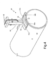
figures 3 and4 show alternative embodiments of the inductor shown infigure 2 . - In
figure 1 , numeral 1 shows as a whole a railway bogie frame made according to a known process. - Specifically, the frame 1 was made by reciprocally connecting, by means of electric soldering, metal portions shaped by means of previous production cycles; during the electric soldering operations, the metal material (typically Fe 510 D1) underwent a thermal cycle which took it from ambient temperature to melting temperature and from melting temperature to ambient temperature in a relatively short time.
- In the illustrated embodiment, frame 1 further comprises two side-
members 3, connected to each other by means of a pair of rectilinear cross-members 4. Each side-member 3 comprises two vertical walls 8 (only one of these delimiting one side facing outwards is visible infigure 1 ) and two upper/lower flange plates members 3. - Each side-
member 3 comprises a rectilinear central portion 3_a and a pair of raised end portions 3_b which extend integrally upwards from opposite ends of the rectilinear central portion 3_a. - The
flat wall 8 is connected by soldering S to theupper flange plate 10, which delimits an upper side of the side-member 3 and to alower flange plate 11 which delimits a lower side of the side-member 3. - Side edges 10_a, 11_a of the upper/
lower flange plates side wall 8, as clearly visible infigure 2 . - The frame 1 further underwent a thermal treatment in a furnace (not shown) under controlled temperature.
- According to the present invention, a local heating of a zone Z of the frame 1 is obtained by arranging an
inductor 20 facing a metal portion of the frame 1 and feeding a medium frequency, alternating current (10-30 KHz) to theinductor 20, so as to generate induced currents in the metal portion facing theinductor 20; such induced currents close in the metal portion which is heated in a concentrated, punctual manner by Joule effect, thus introducing geometric deformations in the zone Z, which contribute, along with the action of specific calibration tools of the known type which act on the frame 1 (e.g. screw jacks, not shown), to straighten and calibrate the frame. - A straightening and calibrating process is thus carried out, consisting in locally heating a zone Z of the frame in which an optimal temperature (approximately 650° C) is reached, which does not damage the frame itself and does not modify the features of the metal.
- Such an optimal temperature is reached in a relatively short time (5, 6 minutes according to the tests carried out by the applicant). The tests carried out by the applicant have shown that the heated metal portion appears without surface/structural defects after the local heating process, thus demonstrating that excessive local temperatures have not been reached.
- The process is implemented without requiring the use of flames and without producing harmful gases.
- The provided thermal contribution may be easily controlled by adjusting the features of the current fed to the
inductor 20. - For this purpose, the
inductor 20 may be fed by the feeder (frequency converter) known under the trademark MINAC® 50/80 from EFD INDUCTION and adapted to provide an output power in the range of 50-80 KW and a variable frequency between 10 and 40 KHz. - The feeder may be provided with a feedback temperature control in the heated zone Z in order to ensure the repeatability of the straightening and calibrating strain-relieving process.
- With specific reference to
figure 2 , theinductor 20 consisting of a tubular copper element having a rectangular section - made according to a first variant - comprises a plurality of turns formed by:
- a first flat, rectilinear,
metal element 25a having a rectangular (or quadrangular) section which has a first end portion connected to a firstU-shaped bridge element 26a connected to afirst feeding terminal 27 of the inductor 20 - the firstrectilinear element 25a having a rectangular section has a second end portion connected to a secondU-shaped bridge element 28a; - a second flat, rectilinear,
metal element 25b having a rectangular (or quadrangular) section, having a first end portion connected to a first U-shaped bridge element 26b, connected to asecond feeding terminal 29 of the inductor 20 - the secondrectilinear metal element 25b having a rectangular section has a second end portion connected to a secondU-shaped bridge element 28b; and - a rectilinear, metal bridge element 30 (transparently shown by dotted lines) which is transversal to the first/
second element 25a/25b which reciprocally interconnects the firstU-shaped bridge element 26a and the secondU-shaped bridge element 28b. - The
inductor 20 is arranged with therectilinear elements flat wall 8 and with the U-shapedbridge elements flange plates - In this manner, the
inductor 20 has shaped turns so as to make a profile which mimics the profile of a section of the portion subjected to heating by forming an air gap having a constant value (typically of 3-5 mm). - With specific reference to
figure 3 , the inductor 20 - made according to a second variant - comprises a plurality of turns formed by: - a first flat,
rectilinear metal element 35a having a rectangular (or quadrangular section), which has a first end portion connected to a firstU-shaped bridge element 36a, connected to afirst feeding terminal 37 of theinductor 20; - a second flat,
rectilinear metal element 35b having a rectangular (or quadrangular section), which has a first end portion connected to a firstU-shaped bridge element 36b connected to a second feeding terminal 39 of theinductor 20; and - a
rectilinear metal element 40 which reciprocally interconnects the end portions of the first/second flatrectilinear element - The
inductor 20 is arranged with therectilinear elements flat wall 42 of the frame 1 and with the U-shapedbridge elements wall 42. - Also in this case, an air gap having a constant value (typically of 3-5 mm) is formed.
- With specific reference to
figure 4 , the inductor 20 - made according to a third variant - is shaped so that it may be used with a cylindricaltubular portion 44 of the frame 1 and comprises a plurality of turns formed by: - a first arch-shaped,
metal element 50 having a rectangular section provided withend portions conductive spacer elements - a second arch-shaped,
metal element 52 having a rectangular section provided with a first end portion, connected to thespacer element 51a, and with a second end portion, connected to afirst feeding terminal 53 of theinductor 20, which extends in a radial direction; and - a third arch-shaped,
metal element 54 having a rectangular section, provided with a first end portion connected to thespacer element 51b, and with a second end portion connected to a second feeding terminal 55 of theinductor 20, which extends in a radial direction. - In this manner, the turns lay on a cylindrical surface with is arranged at a constant distance from the cylindrical
tubular portion 44 for making the air gap having a constant value.
Achannel 60 is made, which extends through the turns and the terminals belonging to the inductor 20 (in such a case, the turns may be formed by a rectangular-section tube); such achannel 60 has a feeding opening in which cooling water from a feeding circuit (not shown) is introduced, and a discharge opening. The forced flow of water from the feeder (e.g. the frequency converter MINAC® 50/80 is adapted to generate a cooling water flow) allows to cool theinductor 20 thus preventing a possible damage thereof due to an extended use.
Claims (10)
- A method of straightening and calibrating a railway bogie frame (1) wherein said frame (1) is formed by reciprocally connecting, by means of electric soldering operations, metal portions shaped by means of previous production cycles; during the electric soldering operations, the metal material undergoes a thermal cycle which produces melted zones (ZF) and thermally altered zones (ZTA) in which residual strains introduced by rapidly heating/cooling the metal are present, said frame being subjected to a step of heating in a furnace which does not completely eliminate the distortions in the frame because some parts thereof may not be aligned with respect to the nominal shape;
said straightening and calibrating method by heating comprising the step of applying loads to said frame and punctually heating at least one portion of the frame,
characterized in that said step of heating comprises the steps of: arranging an inductor (20) facing said portion and feeding an alternating current to the inductor (20) so as to generate induced currents in the metal portion facing the inductor (20); such induced currents close in the metal portion, which is heated in a concentrated, punctual manner by Joule effect. - A method according to claim 1, wherein the step of adjusting the current frequency from 10 to 40 KHz is included.
- A method according to claim 1 or 2, wherein the step of arranging shaped conductors forming turns of said inductor (20) at a constant distance from said metal portion for making an air gap with a constant value is included.
- A method according to claim 3, wherein the inductor (20) has turns shaped so as to make a profile which mimics the profile of a section of the portion subjected to heating.
- A method according to claim 3 or 4, wherein said air gap has a value in the range of 3-5 millimeters.
- A method according to any one of the preceding claims, wherein the step of arranging said inductor comprises the steps of arranging at least one first flat, rectilinear metal element (25a) facing and coplanar to a flat wall (8) of said frame.
- A method according to any one of the preceding claims, wherein the step of arranging said inductor comprises the step of adjusting the position of a U-shaped bridge element (26a,26b; 28a,28b) with respect to said frame (1) so that said U-shaped bridge element accommodates one end edge (10_a, 11_a) of a wall (10, 11) of said frame.
- A method according to any one of the claims from 1 to 6, wherein said inductor comprises a plurality of turns formed by metal elements which lay on a cylindrical surface; said method comprising the step of adjusting the position of said turns so that said cylindrical surface has a constant distance with respect to said portion of the frame.
- A method according to any one of the preceding claims, wherein the step of cooling said inductor is included.
- A method according to claim 9, wherein the step of cooling said inductor comprises the step of making a flow of cooling fluid in a pipe which extends through the turns made by said inductor.
Priority Applications (2)
| Application Number | Priority Date | Filing Date | Title |
|---|---|---|---|
| EP08425762A EP2192016A1 (en) | 2008-11-26 | 2008-11-26 | Method of straightening and calibrating a railway bogie frame by means of magnetic induction heating |
| EP20090177242 EP2192017B1 (en) | 2008-11-26 | 2009-11-26 | Method of straightening and calibrating a railway bogie frame by means of magnetic induction heating |
Applications Claiming Priority (1)
| Application Number | Priority Date | Filing Date | Title |
|---|---|---|---|
| EP08425762A EP2192016A1 (en) | 2008-11-26 | 2008-11-26 | Method of straightening and calibrating a railway bogie frame by means of magnetic induction heating |
Publications (1)
| Publication Number | Publication Date |
|---|---|
| EP2192016A1 true EP2192016A1 (en) | 2010-06-02 |
Family
ID=40559725
Family Applications (2)
| Application Number | Title | Priority Date | Filing Date |
|---|---|---|---|
| EP08425762A Withdrawn EP2192016A1 (en) | 2008-11-26 | 2008-11-26 | Method of straightening and calibrating a railway bogie frame by means of magnetic induction heating |
| EP20090177242 Active EP2192017B1 (en) | 2008-11-26 | 2009-11-26 | Method of straightening and calibrating a railway bogie frame by means of magnetic induction heating |
Family Applications After (1)
| Application Number | Title | Priority Date | Filing Date |
|---|---|---|---|
| EP20090177242 Active EP2192017B1 (en) | 2008-11-26 | 2009-11-26 | Method of straightening and calibrating a railway bogie frame by means of magnetic induction heating |
Country Status (1)
| Country | Link |
|---|---|
| EP (2) | EP2192016A1 (en) |
Cited By (1)
| Publication number | Priority date | Publication date | Assignee | Title |
|---|---|---|---|---|
| JP2012046069A (en) * | 2010-08-26 | 2012-03-08 | East Japan Railway Co | Method for manufacturing railroad vehicle truck |
Families Citing this family (2)
| Publication number | Priority date | Publication date | Assignee | Title |
|---|---|---|---|---|
| DE102017218645A1 (en) * | 2017-10-19 | 2019-04-25 | Zf Friedrichshafen Ag | Inductor and method for inductive heating of a joint for a vehicle |
| CN114618906B (en) * | 2022-02-16 | 2023-03-28 | 江苏科技大学 | Induction heating leveling system with constant-gap heating device and method thereof |
Citations (5)
| Publication number | Priority date | Publication date | Assignee | Title |
|---|---|---|---|---|
| US2428825A (en) * | 1941-02-27 | 1947-10-14 | Linde Air Prod Co | Method of controlling distortion, straightening distorted objects, and/or altering the shape of metal objects |
| US3769102A (en) * | 1968-12-20 | 1973-10-30 | Etude Exploit Des Procedes Cla | Method for levelling the decks of ships |
| US4668850A (en) * | 1984-01-12 | 1987-05-26 | Akebono Brake Industry Co. Ltd. | High frequency induction heating device for brake shoe lining |
| DE19738976A1 (en) * | 1997-05-14 | 1998-11-19 | Horn Klaus | Apparatus for thermal straightening of a metal component |
| EP1056312A2 (en) * | 1998-03-16 | 2000-11-29 | KUKA Schweissanlagen GmbH | Heating device and heating process |
-
2008
- 2008-11-26 EP EP08425762A patent/EP2192016A1/en not_active Withdrawn
-
2009
- 2009-11-26 EP EP20090177242 patent/EP2192017B1/en active Active
Patent Citations (5)
| Publication number | Priority date | Publication date | Assignee | Title |
|---|---|---|---|---|
| US2428825A (en) * | 1941-02-27 | 1947-10-14 | Linde Air Prod Co | Method of controlling distortion, straightening distorted objects, and/or altering the shape of metal objects |
| US3769102A (en) * | 1968-12-20 | 1973-10-30 | Etude Exploit Des Procedes Cla | Method for levelling the decks of ships |
| US4668850A (en) * | 1984-01-12 | 1987-05-26 | Akebono Brake Industry Co. Ltd. | High frequency induction heating device for brake shoe lining |
| DE19738976A1 (en) * | 1997-05-14 | 1998-11-19 | Horn Klaus | Apparatus for thermal straightening of a metal component |
| EP1056312A2 (en) * | 1998-03-16 | 2000-11-29 | KUKA Schweissanlagen GmbH | Heating device and heating process |
Cited By (1)
| Publication number | Priority date | Publication date | Assignee | Title |
|---|---|---|---|---|
| JP2012046069A (en) * | 2010-08-26 | 2012-03-08 | East Japan Railway Co | Method for manufacturing railroad vehicle truck |
Also Published As
| Publication number | Publication date |
|---|---|
| EP2192017A3 (en) | 2012-01-25 |
| EP2192017A2 (en) | 2010-06-02 |
| EP2192017B1 (en) | 2013-05-15 |
Similar Documents
| Publication | Publication Date | Title |
|---|---|---|
| JP4673656B2 (en) | Hot press forming equipment | |
| JP5574772B2 (en) | Spring energization heating method and apparatus | |
| EP2596937A1 (en) | System and method of adjusting the equilibrium temperature of an inductively-heated susceptor | |
| IE922923A1 (en) | Method and apparatus for welding workpieces made of superalloys | |
| CN101448347B (en) | Method for manufacturing induction coil used for medium frequency induction heating | |
| EP2192016A1 (en) | Method of straightening and calibrating a railway bogie frame by means of magnetic induction heating | |
| CN104878330A (en) | Method for optimizing repaired tissue of large workpiece based on local heat treatment realized by induction heating | |
| CA2670142C (en) | Method and apparatus for the heat treatment of welds | |
| US10260118B2 (en) | Post-treating a hardened metal formed part | |
| JP6262959B2 (en) | Aluminum alloy component manufacturing method and aluminum alloy plate press forming apparatus | |
| EP2900036A1 (en) | High-frequency induction heating device and processing device | |
| JP5987420B2 (en) | Electric heating method and hot press molding method | |
| CN206767926U (en) | Heater and shaping furnace | |
| KR101312729B1 (en) | Induction heater device | |
| RU2551045C1 (en) | Method of thermal treatment of weld joints produced by linear friction welding | |
| JP2020002466A (en) | Heat treatment apparatus | |
| WO2016017147A1 (en) | Direct resistance heating method and press-molded product manufacturing method | |
| RU2413010C1 (en) | Procedure and device for heat treatment of weld seams | |
| JPS6210172B2 (en) | ||
| CN107511550A (en) | A kind of high-frequency induction brazing device and method of aluminum bronze soldered fitting | |
| JPH0742515B2 (en) | Induction heating control method for ERW pipe welds | |
| CN214612662U (en) | High-frequency quenching device for pipe fitting die | |
| KR101675005B1 (en) | High frequency heating equipment and method using the same | |
| US3472992A (en) | Crossfield inductor for inductively heating workpieces of varying cross section | |
| Grozdanov et al. | Induction Brazing Process Control |
Legal Events
| Date | Code | Title | Description |
|---|---|---|---|
| PUAI | Public reference made under article 153(3) epc to a published international application that has entered the european phase |
Free format text: ORIGINAL CODE: 0009012 |
|
| AK | Designated contracting states |
Kind code of ref document: A1 Designated state(s): AT BE BG CH CY CZ DE DK EE ES FI FR GB GR HR HU IE IS IT LI LT LU LV MC MT NL NO PL PT RO SE SI SK TR |
|
| AX | Request for extension of the european patent |
Extension state: AL BA MK RS |
|
| AKY | No designation fees paid | ||
| REG | Reference to a national code |
Ref country code: DE Ref legal event code: 8566 |
|
| STAA | Information on the status of an ep patent application or granted ep patent |
Free format text: STATUS: THE APPLICATION IS DEEMED TO BE WITHDRAWN |
|
| 18D | Application deemed to be withdrawn |
Effective date: 20101203 |