EP2191327B1 - Ambient lighting for an image projector - Google Patents
Ambient lighting for an image projector Download PDFInfo
- Publication number
- EP2191327B1 EP2191327B1 EP08807570A EP08807570A EP2191327B1 EP 2191327 B1 EP2191327 B1 EP 2191327B1 EP 08807570 A EP08807570 A EP 08807570A EP 08807570 A EP08807570 A EP 08807570A EP 2191327 B1 EP2191327 B1 EP 2191327B1
- Authority
- EP
- European Patent Office
- Prior art keywords
- ambient light
- image
- light beam
- reflector
- light
- Prior art date
- Legal status (The legal status is an assumption and is not a legal conclusion. Google has not performed a legal analysis and makes no representation as to the accuracy of the status listed.)
- Not-in-force
Links
- 101150016901 ALB1 gene Proteins 0.000 claims abstract description 11
- 101100274294 Arabidopsis thaliana CHLD gene Proteins 0.000 claims abstract description 11
- 101100434646 Mus musculus Alb gene Proteins 0.000 claims abstract description 11
- 102100036774 Afamin Human genes 0.000 claims abstract description 9
- 101000928239 Homo sapiens Afamin Proteins 0.000 claims abstract description 9
- 230000006798 recombination Effects 0.000 description 9
- 238000005215 recombination Methods 0.000 description 9
- 239000003086 colorant Substances 0.000 description 6
- 230000003416 augmentation Effects 0.000 description 5
- 101710179738 6,7-dimethyl-8-ribityllumazine synthase 1 Proteins 0.000 description 2
- 101710186608 Lipoyl synthase 1 Proteins 0.000 description 2
- 101710137584 Lipoyl synthase 1, chloroplastic Proteins 0.000 description 2
- 101710090391 Lipoyl synthase 1, mitochondrial Proteins 0.000 description 2
- 230000001419 dependent effect Effects 0.000 description 2
- 230000005540 biological transmission Effects 0.000 description 1
- 230000021615 conjugation Effects 0.000 description 1
- 230000000007 visual effect Effects 0.000 description 1
Images

Classifications
-
- G—PHYSICS
- G03—PHOTOGRAPHY; CINEMATOGRAPHY; ANALOGOUS TECHNIQUES USING WAVES OTHER THAN OPTICAL WAVES; ELECTROGRAPHY; HOLOGRAPHY
- G03B—APPARATUS OR ARRANGEMENTS FOR TAKING PHOTOGRAPHS OR FOR PROJECTING OR VIEWING THEM; APPARATUS OR ARRANGEMENTS EMPLOYING ANALOGOUS TECHNIQUES USING WAVES OTHER THAN OPTICAL WAVES; ACCESSORIES THEREFOR
- G03B21/00—Projectors or projection-type viewers; Accessories therefor
- G03B21/14—Details
- G03B21/26—Projecting separately subsidiary matter simultaneously with main image
-
- G—PHYSICS
- G03—PHOTOGRAPHY; CINEMATOGRAPHY; ANALOGOUS TECHNIQUES USING WAVES OTHER THAN OPTICAL WAVES; ELECTROGRAPHY; HOLOGRAPHY
- G03B—APPARATUS OR ARRANGEMENTS FOR TAKING PHOTOGRAPHS OR FOR PROJECTING OR VIEWING THEM; APPARATUS OR ARRANGEMENTS EMPLOYING ANALOGOUS TECHNIQUES USING WAVES OTHER THAN OPTICAL WAVES; ACCESSORIES THEREFOR
- G03B21/00—Projectors or projection-type viewers; Accessories therefor
- G03B21/13—Projectors for producing special effects at the edges of picture, e.g. blurring
-
- H—ELECTRICITY
- H04—ELECTRIC COMMUNICATION TECHNIQUE
- H04N—PICTORIAL COMMUNICATION, e.g. TELEVISION
- H04N9/00—Details of colour television systems
- H04N9/12—Picture reproducers
- H04N9/31—Projection devices for colour picture display, e.g. using electronic spatial light modulators [ESLM]
- H04N9/3141—Constructional details thereof
- H04N9/315—Modulator illumination systems
- H04N9/3152—Modulator illumination systems for shaping the light beam
-
- H—ELECTRICITY
- H04—ELECTRIC COMMUNICATION TECHNIQUE
- H04N—PICTORIAL COMMUNICATION, e.g. TELEVISION
- H04N9/00—Details of colour television systems
- H04N9/12—Picture reproducers
- H04N9/31—Projection devices for colour picture display, e.g. using electronic spatial light modulators [ESLM]
- H04N9/3141—Constructional details thereof
- H04N9/315—Modulator illumination systems
- H04N9/3164—Modulator illumination systems using multiple light sources
-
- H—ELECTRICITY
- H04—ELECTRIC COMMUNICATION TECHNIQUE
- H04N—PICTORIAL COMMUNICATION, e.g. TELEVISION
- H04N9/00—Details of colour television systems
- H04N9/64—Circuits for processing colour signals
- H04N9/73—Colour balance circuits, e.g. white balance circuits or colour temperature control
-
- G—PHYSICS
- G02—OPTICS
- G02B—OPTICAL ELEMENTS, SYSTEMS OR APPARATUS
- G02B6/00—Light guides; Structural details of arrangements comprising light guides and other optical elements, e.g. couplings
- G02B6/0001—Light guides; Structural details of arrangements comprising light guides and other optical elements, e.g. couplings specially adapted for lighting devices or systems
- G02B6/0011—Light guides; Structural details of arrangements comprising light guides and other optical elements, e.g. couplings specially adapted for lighting devices or systems the light guides being planar or of plate-like form
Definitions
- the invention relates to a system which projects both an image light beam and an adjacent ambient light beam on a projection area.
- the invention further relates to a front projector which comprises such a system.
- US 7,071,897 B2 discloses a display system for displaying images of high resolution on a main screen, and augmentation images in augmentation regions located around the main screen.
- the viewing experience is enhanced by the presence of the augmentation images because of the increase in visual information conveyed to the viewers.
- the augmentation regions lie outside the foveal field of view of the viewers, so the augmentation images can be of lower resolution than the high resolution images displayed on the main screen.
- the display system comprises a main projector which projects the high resolution images on the main screen, a left and right panel projector which project the low resolution images on left and right panel screens flanking the main screen at left and right sides, respectively.
- This embodiment further comprises first and second right side and first and second left side light sources to project light on the side walls of the room, and left and right ceiling light sources to project light on the ceiling of the room.
- US 7,180,529 B2 discloses an immersive image viewing system projecting both an image light beam and an adjacent ambient light beam on a projection area.
- a first aspect of the invention provides a system as claimed in claim 1.
- a second aspect of the invention provides a front projector as claimed in claim 13.
- Advantageous embodiments are defined in the dependent claims.
- a system in accordance with the first aspect of the invention projects an image light beam on a projection area to display an image on the projection area.
- the image may be any information such as for example a photograph, video, or computer generated information.
- the image may be obtained from a storage medium or may be a received broadcast.
- An ambient light generator which generates an ambient light beam, comprises an ambient light source, a collimator or a light-guide, and a reflector.
- the ambient light source generates ambient light.
- the collimator or the light-guide receives the ambient light generated by the ambient light source at an input window and supplies the ambient light beam which is reflected towards the projection area via the reflector.
- the reflected ambient light beam impinges on an ambient lighting area adjacent the image.
- the ambient light source comprises a LED (Light Emitting Diode) emitting light with a single color, or a plurality of LED's emitting different colors.
- the system comprises a projection lens to project the image light beam on the projection area.
- the ambient light generator is arranged at least partly around the projection lens.
- the ambient light generator may only produce an ambient lighting at the left or right side of the image projected via the projection lens.
- the ambient light generator may produce an ambient lighting at the top of bottom of the projected image, or the ambient lighting may surround the projected image.
- the ambient light generator comprises a collimator.
- the ambient light source, the collimator and the reflector are arranged such that the ambient light source is nearest to the projection lens, and the collimator is in-between the ambient light source and the reflector.
- the collimator and reflector are designed to obtain a sharp cut-off at a border of the ambient lighting area adjacent the image to minimally disturb the projected image by the ambient light beam.
- collimator and reflector designs are known as such from the International Publications WO 2006/033040 and WO 2006/033042 .
- the ambient light generator is arranged in parallel with a plane of the projection lens, or in the plane of the projection lens.
- the plane of the projection lens is defined as a plane through the projection lens, which plane extends substantially perpendicular to the image light beam traversing the projection lens. It is relatively easy to align such an ambient light generator with respect to the projection lens.
- a mirror is used to project the image light beam.
- a front projector using a mirror is as such known from WO 2004/112386 .
- the image light beam is reflected by a front plane of the mirror towards the projection area.
- the ambient light generator comprises the light guide which is arranged at least partly at a back plane of the mirror. At the back plane of the mirror ample space is available to support the ambient light generator. Further, if the ambient light generator is attached to the mirror, the alignment of the ambient light beam with respect to image area is simple.
- the light guide may be a single light guide which ends at least partly along one side of the mirror to provide ambient light at the associated side of the image. Alternatively, two or more light guides may be used to obtain ambient light at more than one side of the image.
- the light-guide is arranged in parallel with the back plane and protrudes with a protruding part at least partly from behind the back plane.
- the protruding part comprises a light output window.
- the light-guide receives the ambient light emitted by the ambient light source at an input window and supplies the ambient light beam to the reflector.
- the reflector reflects the ambient light beam via the output window towards the projection area.
- the length of the light guide is substantially identical to a length of the back plane of the mirror to obtain an optimal mixing of the ambient light radiated by ambient light source if differently colored light emitters are used.
- the light guide is shaped to have an increasing width defined in a direction parallel to the back plane and perpendicular to a direction extending from the ambient light source towards the reflector.
- Such a shape has the advantage that total internal reflection is maintained.
- the width may increase in the direction extending from the ambient light source towards the reflector in a direction perpendicular to the back plane.
- the ambient light source comprises a plurality of differently colored light emitters.
- the different colors may be selected such that it is possible to generate white light.
- the different colors may be selected to correspond to the primaries of the pixels of a display panel which generates the to be projected image to obtain an optimum match between the colors which can be generated by the ambient lighting and the colors of the projected image.
- the system comprises adjustment provisions enabling an adjustment of a position of the ambient light area with respect to a center of the image. This enables to obtain a correct position of the ambient light area for different dimensions of image.
- the different dimensions of the image are due to the use of different projectors, a different distance of a particular projector to the projection area, or zooming the image to be projected.
- the adjustment provisions apply a tilt to the collimator, the light-guide or the reflector.
- the ambient light generator is an integral part of a front projector. This integral part may be positioned inside the cabinet of the front projector or may be factory (or by a service action) attached to the projection lens or mirror. There is no need for the user to align the system.
- the ambient light generator is a separate accessory for the front projector.
- the accessory may be attached to the front projector by the user.
- Fig. 1 schematically shows an embodiment of a front projector with a projection lens.
- the front projector FP comprises three display panels DP1, DP2 and DP3, a recombination cube RC (in literature also referred to as X-prism), an ambient light source LS, a projection lens PL, and a signal processor SP.
- a recombination cube RC in literature also referred to as X-prism
- an ambient light source LS ambient light source
- PL projection lens
- SP signal processor SP
- this embodiment will be explained by assuming that the display panel DP1 provides the red part FP1 of the image, the display panel DP2 the green part FP2 and the display panel DP3 the blue part FP3.
- any other set of primary colors instead of red, green and blue may be used as well.
- the light sources illuminating the display panel DP1, DP2 and DP3 are not shown.
- the red image part FP1 generated by the display panel DP1 enters the recombination cube RC at its input side IS1 and is reflected by the semi transparent color reflector M1 which reflects red light and transmits green light.
- the red light originating from the display panel DP1 is reflected by the semi transparent color reflector M1 towards the output side OS of the recombination cube RC.
- the blue image part FP3 generated by the display panel DP3 enters the recombination cube RC at its input side IS3 and is reflected by the semi transparent color reflector M2 which reflects blue light and transmits green light.
- the blue light originating from the display panel DP3 is reflected by the semi transparent color reflector M2 towards the output side OS of the recombination cube RC.
- the green light originating from the display panel DP2 passes through both the semi transparent color reflectors M1 and M2 and also leaves the recombination cube RC at the output side OS.
- the image beam ILB is projected by the projection lens PL on the as the image PI on the projection area PA.
- the ambient light source LS is arranged around the projector lens LS and emits ambient light into the input side of a collimator CO.
- the ambient light beam leaves the collimator CO at its output side which is directed towards a reflector RF.
- the reflector RF is shaped to reflect the ambient light beam which leaves the collimator CO as the ambient light beam ALB towards the projection area PA.
- the ambient light beam is projected to illuminate the ambient light areas ALI directly adjacent to the projected image PI.
- a gap may be present between the projected image PI and the ambient light areas ALI.
- the ambient light source LS, the collimator and the reflector mentioned surround the projector lens LS, for example as a ring shape or as a square shape corresponding to the straight sides of the display panels DP1, DP2 and DP3. Further, it has to be noted that when ambient light is mentioned, it is meant the light generated by the ambient light source(s) and not the light present in the ambient surroundings of the front projector FP.
- the ambient light source LS, the collimator CO and the reflector RF must not extend over a complete circle. For example, if only ambient light has to be generated at the left and right sides of the projected image PI, two light sources LS, two collimators CO, and two reflectors RF may be used at opposite sides of the projection lens PL. Now, the reflectors RF may form two opposite sides of a rectangle. If the ambient light has to be generated at both the left and right sides and the top and bottom sides of the projected image PI, four light sources LS, collimators CO and reflectors RF may be used instead of a single one which is arranged in a rectangle.
- the collimator and reflector may be designed to obtain a sharp cut-off at a border of the ambient lighting area adjacent the image to minimally disturb the projected image by the ambient light beam.
- Such collimator and reflector designs are known as such from the International Publications WO 2006/033040 and WO 2006/033042 .
- the combination of the ambient light source(s) LS, the collimator(s) CO and the reflector(s) RF may be arranged in a plane perpendicular to the image light beam ILB (or in parallel with the output side OS of the recombination cube RC). Preferably, this plane runs through the projection lens PL.
- the ambient light source LS is arranged nearest to the side of the projection lens PL, and the collimator CO is positioned in-between the ambient light source LS and the reflector RF.
- This arrangement has the advantage that the combination of the ambient light source LS, the collimator CO and the reflectors can be directly or indirectly attached to the projection lens PL and provide the ambient light to be projected in the same plane as the image to be projected.
- the arrangement of the ambient light source LS and the collimator CO must not lie in the previously defined perpendicular plane.
- the light beam leaving the collimator CO may have an angle with this plane.
- the light source LS may be positioned nearer to the recombination cube RC than the collimator CO.
- the reflector RF has to be adapted correspondingly to still project the ambient light beam ALB on the same position on the display area PA.
- the signal processor SP supplies drive signals DP1, DS2 and DS3 to the display panels DP1, DP2 and DP3, respectively to control the transmission of their pixels in accordance with the input image signal IDS. Because three display panels DP I , DP2 and DP3 are used, the red, green and blue pixels may be generated coincidently. If a single display panel is present the red, green and blue sub-images may be generated time sequentially, for example by sequentially changing the color of the light impinging on the single display panel. The recombination cube RC is superfluous if a single display panel is used.
- An adjuster AM is mechanically coupled to the reflector RF to tilt the reflector RF to change the position of the ambient light area ALI.
- the adjuster AM may be mechanically coupled to the collimator CO to tilt the collimator.
- the reflector RF may be a mechanically separate mirror which can be tilted separately from the collimator CO.
- the whole assembly of ambient light source LS, collimator CO and reflector RF may be tilted.
- Fig. 2 schematically shows an embodiment of a front projector with a projection mirror.
- the front projector comprises a projection unit (not shown) which generates an image which is projected on the projection area PI via the mirror MI.
- a front projector using such a projection unit and a mirror is disclosed in WO 2004/112386 .
- the ambient light generator is attached to the mirror MI.
- the light beam from the projector is indicated by LBP.
- the mirror MI has a front plane FPM which is reflective and thus reflects the image light beam towards the projection area PA.
- the mirror MI has a back plane BPM opposite to the front plane FPM.
- a stack of a first combination and a second combination of an ambient light source and a light-guide are arranged at the back plane BPM and in parallel with the back plane BPM.
- the first combination comprises a light source LS1 and a light-guide LG1
- the second combination comprises a light source LS2 and a light-guide LG2.
- the light-guide LG 1 has a light input window IW1 near or at a particular edge of the mirror MI, and a reflector RF1 is arranged at an edge of the mirror MI opposite to the particular edge.
- the ambient light source LS 1 is provided at the light input window of the light-guide LG1.
- the light-guide LG1 has to protrude from behind the back plane of the mirror MI such that the reflector RF 1 is able to reflect the light in the light-guide LG 1 via an output window OW1 towards the projection area PA.
- the ambient light beam leaving the output window OW1 is referred to as ALB1.
- the reflector RF1 is arranged under an angle of 45 degrees with the back plane BPL and the output window OW1 extends in parallel with the back plane BPM. The actual orientation of the reflector RF1 and the output window OW1 may be selected differently. What counts is that the ambient light beam ALB1 is directed to the desired area.
- the second light-guide LG2 has a light input window IW2 near or at the edge opposite to the particular edge, and the reflector RF2 is arranged at the particular edge.
- the ambient light source LS2 is provided at the light input window of the light-guide LG2.
- the light-guide LG2 has to protrude from behind the back plane of the mirror MI such that the reflector RF2 is able to reflect the light in the light-guide LG2 via an output window OW2 towards the projection area PA.
- the ambient light beam leaving the output window OW2 is referred to as ALB2.
- the reflector RF2 is arranged under an angle of 45 degrees with the back plane BPL and the output window OW2 extends in parallel with the back plane BPM. The actual orientation of the reflector RF2 and the output window OW2 may be selected differently.
- the ambient light sources LS 1 and LS2 may comprise a plurality of differently colored LED's.
- an adjuster (AM in Fig. 1 ) may be mechanically coupled with the reflector RF1, RF2 if the reflector is mechanically separated from the collimator CO.
- the adjuster AM may be mechanically coupled with the light guide LG1, LG2 if the reflector RF1, RF2 is one part with the light-guide LG1, LG2.
- the adjuster AM may be mechanically coupled with both the light-guide LG1, LG2 and the reflector RF1, RF2 to tilt the reflector and light-guide to adjust the position of the ambient light area ALI.
- the adjuster AM may tilt the assembly of the light source, the collimator, the light guide and the reflector.
- the reflector may be one part with the light-guide.
- the assembly shown in Fig. 2 is rotated over 90 degrees around the central axis perpendicular to the mirror surface, such that the ambient light is projected at left and right sides of the image instead at top and bottom sides.
- the ambient light may be provided at top, bottom, left and right sides of the mirror surface.
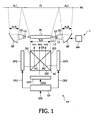
- Fig. 3 schematically shows an embodiment of a light guide.
- the light guide LG1 shown in Fig. 3 may be attached to the back plane BPM of the mirror MI as shown in Fig. 2 .
- the light-guide LG 1 has a trapezoidal shape with an input window IW1 which is relatively small with respect to the output window OW1.
- the dimensions of the input window IW1 are related the dimensions and number of light emitters used in the light source LS1.
- the dimensions of the output window OW1 are defined by the dimensions of the area to be covered by the ambient light beam ALB1.
- the trapezoidal shape has the advantage that total internal reflection is maintained.
- the light guide LG1 may also become wider in the direction from the ambient light source LS1 towards output window OW 1 in a direction perpendicular to the mirror surface.
- the width of the input window IW1 is 2 mm and the width of the output window OW1 is 7 mm.
- the light guide LG2 shown in Fig. 2 may have the same shape but has its input window IW2 near the output window OW1 and its output window OW2 near to the input window IW 1.
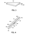
- Fig. 4 schematically shows another embodiment of an ambient light generator using light-guides.
- the light-guides LG1 and LG2 are now arranged in the same plane and are both attached to the back plane BPM of the mirror MI.
- An ambient light source LS is arranged in-between the two light-guides LG 1, LG2 and emits light into both input windows IW 1 and IW2 of the light guides LG 1 and LG2, respectively.
- different light sources may be used for the different light-guides LG1, LG2 such that the color and intensity may be controlled separately.
- the light-guide LG 1 has a reflector RF 1 and an output window OW1 protruding from behind the mirror MI.
- the light-guide LG2 has a reflector RF2 and an output window OW2 protruding from behind the mirror MI.
- the light guide may have a bent shape.
- these light guides may have input windows in parallel to the mirror surface and than have to bent to extend towards the edges of the mirror.
- the color and/or luminance of the ambient light sources may be modulated to obtain an ambient light fitting the content of the projected image PI.
- the color and the intensity of ambient light sources generating the ambient light beam adjacent different sides of the projected image may be controlled differently, for example to vary in accordance with the image content near to the associated border.
- any reference signs placed between parentheses shall not be construed as limiting the claim.
- Use of the verb "comprise” and its conjugations does not exclude the presence of elements or steps other than those stated in a claim.
- the article "a” or “an” preceding an element does not exclude the presence of a plurality of such elements.
- the invention may be implemented by means of hardware comprising several distinct elements, and by means of a suitably programmed computer. In the device claim enumerating several means, several of these means may be embodied by one and the same item of hardware. The mere fact that certain measures are recited in mutually different dependent claims does not indicate that a combination of these measures cannot be used to advantage.
Landscapes
- Engineering & Computer Science (AREA)
- Multimedia (AREA)
- Signal Processing (AREA)
- Physics & Mathematics (AREA)
- General Physics & Mathematics (AREA)
- Projection Apparatus (AREA)
- Non-Portable Lighting Devices Or Systems Thereof (AREA)
- Devices For Indicating Variable Information By Combining Individual Elements (AREA)
Priority Applications (1)
| Application Number | Priority Date | Filing Date | Title |
|---|---|---|---|
| EP08807570A EP2191327B1 (en) | 2007-09-11 | 2008-09-08 | Ambient lighting for an image projector |
Applications Claiming Priority (3)
| Application Number | Priority Date | Filing Date | Title |
|---|---|---|---|
| EP07116121 | 2007-09-11 | ||
| PCT/IB2008/053621 WO2009034513A2 (en) | 2007-09-11 | 2008-09-08 | Ambient lighting for an image display |
| EP08807570A EP2191327B1 (en) | 2007-09-11 | 2008-09-08 | Ambient lighting for an image projector |
Publications (2)
| Publication Number | Publication Date |
|---|---|
| EP2191327A2 EP2191327A2 (en) | 2010-06-02 |
| EP2191327B1 true EP2191327B1 (en) | 2011-06-29 |
Family
ID=40452642
Family Applications (1)
| Application Number | Title | Priority Date | Filing Date |
|---|---|---|---|
| EP08807570A Not-in-force EP2191327B1 (en) | 2007-09-11 | 2008-09-08 | Ambient lighting for an image projector |
Country Status (6)
| Country | Link |
|---|---|
| US (1) | US8356902B2 (enExample) |
| EP (1) | EP2191327B1 (enExample) |
| JP (1) | JP5138041B2 (enExample) |
| CN (1) | CN101802707B (enExample) |
| AT (1) | ATE514971T1 (enExample) |
| WO (1) | WO2009034513A2 (enExample) |
Families Citing this family (12)
| Publication number | Priority date | Publication date | Assignee | Title |
|---|---|---|---|---|
| EP2335115B1 (en) * | 2008-10-17 | 2015-03-04 | TP Vision Holding B.V. | An ambience lighting system for a display device |
| US8755007B2 (en) * | 2011-07-01 | 2014-06-17 | Seiko Epson Corporation | Liquid crystal device, electronic apparatus and lighting device |
| DE102011088794A1 (de) * | 2011-12-16 | 2013-06-20 | Robert Bosch Gmbh | Projektionseinrichtung und Verfahren zum Projizieren eines Bilds in einen Sicht-bereich eines Fahrers eines Fahrzeugs |
| US20130215394A1 (en) * | 2012-02-18 | 2013-08-22 | Rakesh Reddy | Underwater Image Projection Display System and Lighting Control System And Device |
| KR101305249B1 (ko) * | 2012-07-12 | 2013-09-06 | 씨제이씨지브이 주식회사 | 다면 상영 시스템 |
| JP2014032750A (ja) * | 2012-08-01 | 2014-02-20 | Seiko Epson Corp | 照明システム、照明方法および照明プログラム |
| EP2746848A1 (en) * | 2012-12-21 | 2014-06-25 | TP Vision Holding B.V. | Ambient light projection device |
| JP6229972B2 (ja) * | 2013-11-05 | 2017-11-15 | パナソニックIpマネジメント株式会社 | 照明装置 |
| JP2015090405A (ja) * | 2013-11-05 | 2015-05-11 | パナソニックIpマネジメント株式会社 | 照明装置 |
| JP6597963B2 (ja) * | 2015-11-17 | 2019-10-30 | 東芝ライテック株式会社 | 照明装置および照明制御システム |
| AT518894B1 (de) | 2016-09-02 | 2018-02-15 | Trumpf Maschinen Austria Gmbh & Co Kg | Biegemaschine mit einer Biegeinformations-Anzeigevorrichtung |
| FR3079708A1 (fr) * | 2018-03-28 | 2019-10-04 | Johann Bouqueniaux | Procede de projection d'une image sur un ecran a contraste ameliore |
Family Cites Families (14)
| Publication number | Priority date | Publication date | Assignee | Title |
|---|---|---|---|---|
| US7071897B2 (en) * | 2001-07-18 | 2006-07-04 | Hewlett-Packard Development Company, L.P. | Immersive augmentation for display systems |
| US7180663B2 (en) | 2002-06-19 | 2007-02-20 | Robert Bruce Collender | 3D motion picture theatre |
| US7180529B2 (en) | 2002-12-19 | 2007-02-20 | Eastman Kodak Company | Immersive image viewing system and method |
| ATE354911T1 (de) * | 2003-06-12 | 2007-03-15 | Koninkl Philips Electronics Nv | Gerät zur gleichzeitigen bildprojektion und raumbeleuchtung |
| JP2005057410A (ja) | 2003-08-01 | 2005-03-03 | Alpine Electronics Inc | 映像出力装置および方法 |
| US7040764B2 (en) | 2003-10-23 | 2006-05-09 | Hewlett-Packard Development Company, L.P. | Projection system using ambient light |
| EP1551178A1 (en) * | 2003-12-18 | 2005-07-06 | Koninklijke Philips Electronics N.V. | Supplementary visual display system |
| EP1548571A1 (en) | 2003-12-23 | 2005-06-29 | Barco N.V. | Configurable tiled emissive display |
| JP2005251508A (ja) * | 2004-03-03 | 2005-09-15 | Sony Corp | ディスプレイ装置および映像表示方法 |
| US7090358B2 (en) | 2004-03-04 | 2006-08-15 | International Business Machines Corporation | System, apparatus and method of displaying information for foveal vision and peripheral vision |
| ES2515865T3 (es) * | 2004-09-20 | 2014-10-30 | Koninklijke Philips N.V. | Elemento colimador de LED con un reflector semiparabólico |
| EP1794491B1 (en) | 2004-09-20 | 2011-06-29 | Philips Intellectual Property & Standards GmbH | Led collimator element with an asymmetrical collimator |
| CN101069454A (zh) * | 2004-11-30 | 2007-11-07 | 皇家飞利浦电子股份有限公司 | 显示系统 |
| WO2009027903A2 (en) * | 2007-08-28 | 2009-03-05 | Koninklijke Philips Electronics N.V. | A front projector |
-
2008
- 2008-09-08 CN CN2008801065260A patent/CN101802707B/zh not_active Expired - Fee Related
- 2008-09-08 EP EP08807570A patent/EP2191327B1/en not_active Not-in-force
- 2008-09-08 WO PCT/IB2008/053621 patent/WO2009034513A2/en not_active Ceased
- 2008-09-08 AT AT08807570T patent/ATE514971T1/de not_active IP Right Cessation
- 2008-09-08 US US12/676,627 patent/US8356902B2/en not_active Expired - Fee Related
- 2008-09-08 JP JP2010523628A patent/JP5138041B2/ja not_active Expired - Fee Related
Also Published As
| Publication number | Publication date |
|---|---|
| CN101802707B (zh) | 2012-07-04 |
| US20100208211A1 (en) | 2010-08-19 |
| ATE514971T1 (de) | 2011-07-15 |
| US8356902B2 (en) | 2013-01-22 |
| JP5138041B2 (ja) | 2013-02-06 |
| WO2009034513A2 (en) | 2009-03-19 |
| JP2010539523A (ja) | 2010-12-16 |
| WO2009034513A3 (en) | 2009-12-10 |
| EP2191327A2 (en) | 2010-06-02 |
| CN101802707A (zh) | 2010-08-11 |
Similar Documents
| Publication | Publication Date | Title |
|---|---|---|
| EP2191327B1 (en) | Ambient lighting for an image projector | |
| US20120212707A1 (en) | Multi-Segment Imager | |
| US8976080B2 (en) | Multi-segment imager | |
| EP1967020B1 (en) | Rear projector and rear projecting method | |
| JP5637851B2 (ja) | フロントプロジェクタ | |
| US5123729A (en) | Projection display device | |
| US20130033681A1 (en) | Projector | |
| US7360901B2 (en) | Cross dichroic mirror, illuminating device, and projection type video display | |
| JP5175211B2 (ja) | 周囲照明を与える層状光ガイド | |
| CN101189547A (zh) | 多位置照明系统和采用此系统的投影显示系统 | |
| US7604354B1 (en) | Three-dimensional projection apparatus using coaxial optical alignment | |
| JP2009520334A5 (enExample) | ||
| JP2003035884A (ja) | 画像表示装置 | |
| US20080158447A1 (en) | Projection display device | |
| US7862180B2 (en) | Optical system for image projection and image projection apparatus | |
| JP5217207B2 (ja) | プロジェクタ | |
| JP2007293101A (ja) | 背面投射型表示装置及びスクリーン | |
| JP3010806B2 (ja) | 液晶プロジェクタ装置 | |
| KR940006726B1 (ko) | 배면투사형 lcd 프로젝터 광학계 | |
| KR100199875B1 (ko) | 투사형 화상표시장치의 광학계 | |
| KR970008406B1 (ko) | 투사형 화상표시장치 | |
| US20070128751A1 (en) | Display device having uniform brightness | |
| JP2001264726A (ja) | 液晶プロジェクタ |
Legal Events
| Date | Code | Title | Description |
|---|---|---|---|
| PUAI | Public reference made under article 153(3) epc to a published international application that has entered the european phase |
Free format text: ORIGINAL CODE: 0009012 |
|
| AK | Designated contracting states |
Kind code of ref document: A2 Designated state(s): AT BE BG CH CY CZ DE DK EE ES FI FR GB GR HR HU IE IS IT LI LT LU LV MC MT NL NO PL PT RO SE SI SK TR |
|
| AX | Request for extension of the european patent |
Extension state: AL BA MK RS |
|
| 17P | Request for examination filed |
Effective date: 20100610 |
|
| RBV | Designated contracting states (corrected) |
Designated state(s): AT BE BG CH CY CZ DE DK EE ES FI FR GB GR HR HU IE IS IT LI LT LU LV MC MT NL NO PL PT RO SE SI SK TR |
|
| DAX | Request for extension of the european patent (deleted) | ||
| RIC1 | Information provided on ipc code assigned before grant |
Ipc: H04N 9/31 20060101ALI20101223BHEP Ipc: G03B 21/26 20060101AFI20101223BHEP Ipc: G03B 21/13 20060101ALI20101223BHEP Ipc: H04N 9/73 20060101ALI20101223BHEP |
|
| RTI1 | Title (correction) |
Free format text: AMBIENT LIGHTING FOR AN IMAGE PROJECTOR |
|
| GRAP | Despatch of communication of intention to grant a patent |
Free format text: ORIGINAL CODE: EPIDOSNIGR1 |
|
| GRAS | Grant fee paid |
Free format text: ORIGINAL CODE: EPIDOSNIGR3 |
|
| GRAA | (expected) grant |
Free format text: ORIGINAL CODE: 0009210 |
|
| AK | Designated contracting states |
Kind code of ref document: B1 Designated state(s): AT BE BG CH CY CZ DE DK EE ES FI FR GB GR HR HU IE IS IT LI LT LU LV MC MT NL NO PL PT RO SE SI SK TR |
|
| REG | Reference to a national code |
Ref country code: GB Ref legal event code: FG4D |
|
| REG | Reference to a national code |
Ref country code: CH Ref legal event code: EP |
|
| REG | Reference to a national code |
Ref country code: IE Ref legal event code: FG4D |
|
| REG | Reference to a national code |
Ref country code: DE Ref legal event code: R096 Ref document number: 602008007977 Country of ref document: DE Effective date: 20110818 |
|
| REG | Reference to a national code |
Ref country code: DE Ref legal event code: R084 Ref document number: 602008007977 Country of ref document: DE |
|
| REG | Reference to a national code |
Ref country code: NL Ref legal event code: VDEP Effective date: 20110629 |
|
| REG | Reference to a national code |
Ref country code: DE Ref legal event code: R084 Ref document number: 602008007977 Country of ref document: DE Effective date: 20110809 |
|
| PG25 | Lapsed in a contracting state [announced via postgrant information from national office to epo] |
Ref country code: NO Free format text: LAPSE BECAUSE OF FAILURE TO SUBMIT A TRANSLATION OF THE DESCRIPTION OR TO PAY THE FEE WITHIN THE PRESCRIBED TIME-LIMIT Effective date: 20110929 Ref country code: SE Free format text: LAPSE BECAUSE OF FAILURE TO SUBMIT A TRANSLATION OF THE DESCRIPTION OR TO PAY THE FEE WITHIN THE PRESCRIBED TIME-LIMIT Effective date: 20110629 Ref country code: LT Free format text: LAPSE BECAUSE OF FAILURE TO SUBMIT A TRANSLATION OF THE DESCRIPTION OR TO PAY THE FEE WITHIN THE PRESCRIBED TIME-LIMIT Effective date: 20110629 Ref country code: HR Free format text: LAPSE BECAUSE OF FAILURE TO SUBMIT A TRANSLATION OF THE DESCRIPTION OR TO PAY THE FEE WITHIN THE PRESCRIBED TIME-LIMIT Effective date: 20110629 |
|
| PG25 | Lapsed in a contracting state [announced via postgrant information from national office to epo] |
Ref country code: GR Free format text: LAPSE BECAUSE OF FAILURE TO SUBMIT A TRANSLATION OF THE DESCRIPTION OR TO PAY THE FEE WITHIN THE PRESCRIBED TIME-LIMIT Effective date: 20110930 Ref country code: SI Free format text: LAPSE BECAUSE OF FAILURE TO SUBMIT A TRANSLATION OF THE DESCRIPTION OR TO PAY THE FEE WITHIN THE PRESCRIBED TIME-LIMIT Effective date: 20110629 Ref country code: AT Free format text: LAPSE BECAUSE OF FAILURE TO SUBMIT A TRANSLATION OF THE DESCRIPTION OR TO PAY THE FEE WITHIN THE PRESCRIBED TIME-LIMIT Effective date: 20110629 Ref country code: FI Free format text: LAPSE BECAUSE OF FAILURE TO SUBMIT A TRANSLATION OF THE DESCRIPTION OR TO PAY THE FEE WITHIN THE PRESCRIBED TIME-LIMIT Effective date: 20110629 Ref country code: LV Free format text: LAPSE BECAUSE OF FAILURE TO SUBMIT A TRANSLATION OF THE DESCRIPTION OR TO PAY THE FEE WITHIN THE PRESCRIBED TIME-LIMIT Effective date: 20110629 |
|
| PG25 | Lapsed in a contracting state [announced via postgrant information from national office to epo] |
Ref country code: BE Free format text: LAPSE BECAUSE OF FAILURE TO SUBMIT A TRANSLATION OF THE DESCRIPTION OR TO PAY THE FEE WITHIN THE PRESCRIBED TIME-LIMIT Effective date: 20110629 |
|
| PG25 | Lapsed in a contracting state [announced via postgrant information from national office to epo] |
Ref country code: CZ Free format text: LAPSE BECAUSE OF FAILURE TO SUBMIT A TRANSLATION OF THE DESCRIPTION OR TO PAY THE FEE WITHIN THE PRESCRIBED TIME-LIMIT Effective date: 20110629 Ref country code: PT Free format text: LAPSE BECAUSE OF FAILURE TO SUBMIT A TRANSLATION OF THE DESCRIPTION OR TO PAY THE FEE WITHIN THE PRESCRIBED TIME-LIMIT Effective date: 20111031 Ref country code: IS Free format text: LAPSE BECAUSE OF FAILURE TO SUBMIT A TRANSLATION OF THE DESCRIPTION OR TO PAY THE FEE WITHIN THE PRESCRIBED TIME-LIMIT Effective date: 20111029 Ref country code: EE Free format text: LAPSE BECAUSE OF FAILURE TO SUBMIT A TRANSLATION OF THE DESCRIPTION OR TO PAY THE FEE WITHIN THE PRESCRIBED TIME-LIMIT Effective date: 20110629 Ref country code: NL Free format text: LAPSE BECAUSE OF FAILURE TO SUBMIT A TRANSLATION OF THE DESCRIPTION OR TO PAY THE FEE WITHIN THE PRESCRIBED TIME-LIMIT Effective date: 20110629 |
|
| PG25 | Lapsed in a contracting state [announced via postgrant information from national office to epo] |
Ref country code: PL Free format text: LAPSE BECAUSE OF FAILURE TO SUBMIT A TRANSLATION OF THE DESCRIPTION OR TO PAY THE FEE WITHIN THE PRESCRIBED TIME-LIMIT Effective date: 20110629 Ref country code: SK Free format text: LAPSE BECAUSE OF FAILURE TO SUBMIT A TRANSLATION OF THE DESCRIPTION OR TO PAY THE FEE WITHIN THE PRESCRIBED TIME-LIMIT Effective date: 20110629 Ref country code: RO Free format text: LAPSE BECAUSE OF FAILURE TO SUBMIT A TRANSLATION OF THE DESCRIPTION OR TO PAY THE FEE WITHIN THE PRESCRIBED TIME-LIMIT Effective date: 20110629 Ref country code: CY Free format text: LAPSE BECAUSE OF FAILURE TO SUBMIT A TRANSLATION OF THE DESCRIPTION OR TO PAY THE FEE WITHIN THE PRESCRIBED TIME-LIMIT Effective date: 20110629 |
|
| REG | Reference to a national code |
Ref country code: DE Ref legal event code: R119 Ref document number: 602008007977 Country of ref document: DE Ref country code: DE Ref legal event code: R409 Ref document number: 602008007977 Country of ref document: DE |
|
| PG25 | Lapsed in a contracting state [announced via postgrant information from national office to epo] |
Ref country code: MC Free format text: LAPSE BECAUSE OF NON-PAYMENT OF DUE FEES Effective date: 20110930 |
|
| PLBE | No opposition filed within time limit |
Free format text: ORIGINAL CODE: 0009261 |
|
| STAA | Information on the status of an ep patent application or granted ep patent |
Free format text: STATUS: NO OPPOSITION FILED WITHIN TIME LIMIT |
|
| REG | Reference to a national code |
Ref country code: DE Ref legal event code: R409 Ref document number: 602008007977 Country of ref document: DE |
|
| PG25 | Lapsed in a contracting state [announced via postgrant information from national office to epo] |
Ref country code: IT Free format text: LAPSE BECAUSE OF FAILURE TO SUBMIT A TRANSLATION OF THE DESCRIPTION OR TO PAY THE FEE WITHIN THE PRESCRIBED TIME-LIMIT Effective date: 20110629 |
|
| 26N | No opposition filed |
Effective date: 20120330 |
|
| REG | Reference to a national code |
Ref country code: IE Ref legal event code: MM4A |
|
| PG25 | Lapsed in a contracting state [announced via postgrant information from national office to epo] |
Ref country code: DK Free format text: LAPSE BECAUSE OF FAILURE TO SUBMIT A TRANSLATION OF THE DESCRIPTION OR TO PAY THE FEE WITHIN THE PRESCRIBED TIME-LIMIT Effective date: 20110629 |
|
| PG25 | Lapsed in a contracting state [announced via postgrant information from national office to epo] |
Ref country code: IE Free format text: LAPSE BECAUSE OF NON-PAYMENT OF DUE FEES Effective date: 20110908 |
|
| REG | Reference to a national code |
Ref country code: DE Ref legal event code: R097 Ref document number: 602008007977 Country of ref document: DE Effective date: 20120330 |
|
| PG25 | Lapsed in a contracting state [announced via postgrant information from national office to epo] |
Ref country code: MT Free format text: LAPSE BECAUSE OF FAILURE TO SUBMIT A TRANSLATION OF THE DESCRIPTION OR TO PAY THE FEE WITHIN THE PRESCRIBED TIME-LIMIT Effective date: 20110629 |
|
| PG25 | Lapsed in a contracting state [announced via postgrant information from national office to epo] |
Ref country code: ES Free format text: LAPSE BECAUSE OF FAILURE TO SUBMIT A TRANSLATION OF THE DESCRIPTION OR TO PAY THE FEE WITHIN THE PRESCRIBED TIME-LIMIT Effective date: 20111010 |
|
| REG | Reference to a national code |
Ref country code: CH Ref legal event code: PL |
|
| PG25 | Lapsed in a contracting state [announced via postgrant information from national office to epo] |
Ref country code: LU Free format text: LAPSE BECAUSE OF NON-PAYMENT OF DUE FEES Effective date: 20110908 |
|
| PG25 | Lapsed in a contracting state [announced via postgrant information from national office to epo] |
Ref country code: BG Free format text: LAPSE BECAUSE OF FAILURE TO SUBMIT A TRANSLATION OF THE DESCRIPTION OR TO PAY THE FEE WITHIN THE PRESCRIBED TIME-LIMIT Effective date: 20110929 |
|
| PG25 | Lapsed in a contracting state [announced via postgrant information from national office to epo] |
Ref country code: LI Free format text: LAPSE BECAUSE OF NON-PAYMENT OF DUE FEES Effective date: 20120930 Ref country code: CH Free format text: LAPSE BECAUSE OF NON-PAYMENT OF DUE FEES Effective date: 20120930 |
|
| PG25 | Lapsed in a contracting state [announced via postgrant information from national office to epo] |
Ref country code: TR Free format text: LAPSE BECAUSE OF FAILURE TO SUBMIT A TRANSLATION OF THE DESCRIPTION OR TO PAY THE FEE WITHIN THE PRESCRIBED TIME-LIMIT Effective date: 20110629 |
|
| PG25 | Lapsed in a contracting state [announced via postgrant information from national office to epo] |
Ref country code: HU Free format text: LAPSE BECAUSE OF FAILURE TO SUBMIT A TRANSLATION OF THE DESCRIPTION OR TO PAY THE FEE WITHIN THE PRESCRIBED TIME-LIMIT Effective date: 20110629 |
|
| REG | Reference to a national code |
Ref country code: DE Ref legal event code: R082 Ref document number: 602008007977 Country of ref document: DE Representative=s name: MEISSNER, BOLTE & PARTNER GBR, DE |
|
| REG | Reference to a national code |
Ref country code: DE Ref legal event code: R082 Ref document number: 602008007977 Country of ref document: DE Representative=s name: MEISSNER BOLTE PATENTANWAELTE RECHTSANWAELTE P, DE Effective date: 20140328 Ref country code: DE Ref legal event code: R081 Ref document number: 602008007977 Country of ref document: DE Owner name: PHILIPS LIGHTING HOLDING B.V., NL Free format text: FORMER OWNER: KONINKLIJKE PHILIPS ELECTRONICS N.V., EINDHOVEN, NL Effective date: 20140328 Ref country code: DE Ref legal event code: R081 Ref document number: 602008007977 Country of ref document: DE Owner name: KONINKLIJKE PHILIPS N.V., NL Free format text: FORMER OWNER: KONINKLIJKE PHILIPS ELECTRONICS N.V., EINDHOVEN, NL Effective date: 20140328 Ref country code: DE Ref legal event code: R082 Ref document number: 602008007977 Country of ref document: DE Representative=s name: MEISSNER, BOLTE & PARTNER GBR, DE Effective date: 20140328 |
|
| REG | Reference to a national code |
Ref country code: FR Ref legal event code: CD Owner name: KONINKLIJKE PHILIPS ELECTRONICS N.V., NL Effective date: 20141126 Ref country code: FR Ref legal event code: CA Effective date: 20141126 |
|
| REG | Reference to a national code |
Ref country code: FR Ref legal event code: PLFP Year of fee payment: 8 |
|
| REG | Reference to a national code |
Ref country code: FR Ref legal event code: PLFP Year of fee payment: 9 |
|
| REG | Reference to a national code |
Ref country code: GB Ref legal event code: 732E Free format text: REGISTERED BETWEEN 20161006 AND 20161012 |
|
| REG | Reference to a national code |
Ref country code: DE Ref legal event code: R082 Ref document number: 602008007977 Country of ref document: DE Representative=s name: MEISSNER BOLTE PATENTANWAELTE RECHTSANWAELTE P, DE Ref country code: DE Ref legal event code: R081 Ref document number: 602008007977 Country of ref document: DE Owner name: PHILIPS LIGHTING HOLDING B.V., NL Free format text: FORMER OWNER: KONINKLIJKE PHILIPS N.V., EINDHOVEN, NL |
|
| REG | Reference to a national code |
Ref country code: FR Ref legal event code: PLFP Year of fee payment: 10 |
|
| REG | Reference to a national code |
Ref country code: FR Ref legal event code: PLFP Year of fee payment: 11 |
|
| PGFP | Annual fee paid to national office [announced via postgrant information from national office to epo] |
Ref country code: DE Payment date: 20200928 Year of fee payment: 13 Ref country code: FR Payment date: 20200928 Year of fee payment: 13 Ref country code: GB Payment date: 20200925 Year of fee payment: 13 |
|
| REG | Reference to a national code |
Ref country code: DE Ref legal event code: R119 Ref document number: 602008007977 Country of ref document: DE |
|
| GBPC | Gb: european patent ceased through non-payment of renewal fee |
Effective date: 20210908 |
|
| PG25 | Lapsed in a contracting state [announced via postgrant information from national office to epo] |
Ref country code: GB Free format text: LAPSE BECAUSE OF NON-PAYMENT OF DUE FEES Effective date: 20210908 Ref country code: FR Free format text: LAPSE BECAUSE OF NON-PAYMENT OF DUE FEES Effective date: 20210930 Ref country code: DE Free format text: LAPSE BECAUSE OF NON-PAYMENT OF DUE FEES Effective date: 20220401 |