EP2191158B1 - Actuation means for a clutch - Google Patents
Actuation means for a clutch Download PDFInfo
- Publication number
- EP2191158B1 EP2191158B1 EP08801575A EP08801575A EP2191158B1 EP 2191158 B1 EP2191158 B1 EP 2191158B1 EP 08801575 A EP08801575 A EP 08801575A EP 08801575 A EP08801575 A EP 08801575A EP 2191158 B1 EP2191158 B1 EP 2191158B1
- Authority
- EP
- European Patent Office
- Prior art keywords
- master
- oil chamber
- slave
- oil
- line
- Prior art date
- Legal status (The legal status is an assumption and is not a legal conclusion. Google has not performed a legal analysis and makes no representation as to the accuracy of the status listed.)
- Not-in-force
Links
Images


Classifications
-
- F—MECHANICAL ENGINEERING; LIGHTING; HEATING; WEAPONS; BLASTING
- F16—ENGINEERING ELEMENTS AND UNITS; GENERAL MEASURES FOR PRODUCING AND MAINTAINING EFFECTIVE FUNCTIONING OF MACHINES OR INSTALLATIONS; THERMAL INSULATION IN GENERAL
- F16D—COUPLINGS FOR TRANSMITTING ROTATION; CLUTCHES; BRAKES
- F16D48/00—External control of clutches
- F16D48/02—Control by fluid pressure
- F16D2048/0218—Reservoirs for clutch control systems; Details thereof
-
- F—MECHANICAL ENGINEERING; LIGHTING; HEATING; WEAPONS; BLASTING
- F16—ENGINEERING ELEMENTS AND UNITS; GENERAL MEASURES FOR PRODUCING AND MAINTAINING EFFECTIVE FUNCTIONING OF MACHINES OR INSTALLATIONS; THERMAL INSULATION IN GENERAL
- F16D—COUPLINGS FOR TRANSMITTING ROTATION; CLUTCHES; BRAKES
- F16D2500/00—External control of clutches by electric or electronic means
- F16D2500/50—Problem to be solved by the control system
- F16D2500/501—Relating the actuator
Definitions
- the invention relates to a control of a clutch, in particular for a hybrid drive, with a master cylinder whose interior is divided by a master piston in a slave oil space and a donor oil space, the slave oil space via a valve in a first valve position with a tank line to an oil reservoir and in a second valve position is connected to a pressure line from the oil reservoir, and wherein the donor oil space is connected via a working line with the oil chamber of a slave cylinder and via a compensation line in dependence on the position of the master piston with a surge tank.
- the invention furthermore relates to a method for controlling a clutch, in particular for a hybrid drive, in which a slave oil chamber of a master cylinder is filled with oil via a valve which connects the slave oil chamber with a pressure line of an oil reservoir to actuate a working piston in a slave cylinder associated with a clutch wherein the oil is pressed by moving a master piston from a donor oil chamber of the master cylinder via a working line in an oil chamber of the slave cylinder and shifts the working piston in its operating position, wherein for resetting the working piston of the slave oil chamber of the master cylinder separated by the valve from the pressure line and with a Tank line is connected and emptied, being vented in the initial position of the master piston of the donor oil chamber via a surge tank and missing oil volume is compensated.
- hybrid powertrains are also pursuing the goals of increased comfort, performance improvement or emission-free driving. To achieve some of these goals, it is necessary to shut down the internal combustion engine and go purely electric (eg: emission-free driving). In the parallel architecture of a hybrid powertrain, this requires an additional clutch between the engine and the electric motor to separate the engine from the powertrain. This clutch must be driven according to a driving strategy, depending on the operating state.
- a master cylinder In a hydraulic control of a clutch, as for example from the DE 43 09 901 A1 is known, a master cylinder is used, which shifts a defined amount of oil in a slave cylinder. This slave cylinder finally actuates, for example as a central release a clutch. On the master cylinder is released in the rear end position, ie without actuation, a hydraulic connection to a surge tank. Through this connection, the system is vented on the one hand during normal operation, on the other hand is carried out via this connection, an automatic adjustment of the clutch with increasing wear. Automatic control of the clutch requires hydraulic control. Due to this circumstance, two hydraulic circuits are created: the hydraulic control and the hydraulic coupling confirmation section with associated expansion tank.
- a disadvantage of the known control is that with an additional clutch for the entire hydraulic actuation of the corresponding additional space is vorzuhalten.
- the additional reservoir creates a certain amount of additional maintenance, for example the regular check of the level in the reservoir.
- the slave oil space and the donor oil space are connected via a common proportional valve with an oil reservoir.
- the disadvantage here is that although a compensation of the clutch wear by a connection of the donor oil chamber via the proportional valve to the tank line of the oil reservoir is possible, but that due to the lack of its own reservoir tank venting is at best possible.
- Object of the present invention is therefore to propose a control and a method for driving a clutch, which allows a compact and low-maintenance system. Both the functionality of the operating ventilation and the compensation of the clutch wear should be maintained.
- valve connects the slave oil chamber in its first position via a return line to the surge tank and that the surge tank has a compensation volume, the one at its highest point Has overflow, which is connected to the tank line .
- the expansion tank has an overflow, which is connected to the tank line and the slave oil space is not connected directly to the tank line but via the equalization volume or the expansion tank with the oil reservoir, it is possible to form the expansion tank or its compensation volume much smaller than in the prior art.
- the compensation volume is refilled with each actuation of the master cylinder.
- the functionality of the strigentlskyüng as well as the compensation of the clutch wear remains.
- the system can be independently filled with hydraulic oil during initial startup or after maintenance work on the hydraulic clutch actuation path by repeated actuation.
- the master cylinder, the surge tank and the valve are arranged in a housing and form a drive unit.
- a compact and low-maintenance drive unit is achieved, which may be the same for the two clutches of a hybrid drive.
- the drive unit for connection to the slave cylinder has an external working connection, for connection to the oil reservoir or the hydraulic control an external tank connection and an external pressure connection and for connection of a control device with a valve control of the valve to a control connection.
- a seal is arranged between the master piston and master cylinder in a groove so that in an end position of the master piston with emptied slave oil space the opening of the compensation line to the donor oil space is exposed, wherein in one of the seal to Geberölraum towards upstream region between the piston circumference and adjacent Geberzylinderwandung a donor oil chamber with the opening of the compensation line connecting passage is formed. In this position, the venting of the donor oil chamber to the compensation volume through the passage or can be filled or compensated for by a resulting wear of the clutch differential volume in the donor oil chamber with oil from the surge tank.
- the seal which seals the piston when moving relative to the donor oil space, can be arranged both in a circumferential groove of the master piston and in a circumferential groove of the donor cylinder wall.
- the object of the method for controlling a clutch is achieved in connection with the preamble of claim 9, characterized in that the slave oil chamber connected to the emptying via the valve with the surge tank and this is filled, with excess oil via an overflow of the surge tank on the with the tank line connected to the overflow is returned to the oil reservoir.
- the control oil volume is conducted from the slave oil chamber into the expansion tank, and excess oil flows via the overflow back into the oil reservoir of the hydraulic control.
- the compensation volume is thus refilled with each actuation of the master piston.
- an operating venting of the clutch actuation path is ensured via the expansion tank. Due to the overflow and the connection to the oil reservoir, it is possible for the expansion tank with the same function over the known expansion tanks relatively small, i. form with low compensation volume. A check of the level of the surge tank is unnecessary by the inventive method.
- the master cylinder is actuated several times in a completely empty clutch actuation path for complete replenishment of donor oil chamber and expansion tank.
- the system can be filled automatically with hydraulic oil during initial commissioning or after maintenance work on the hydraulic clutch actuation path.
- the control 1 of a clutch consists essentially of a drive unit 2, a hydraulic control 3, a control unit 4 and a slave cylinder 5 for actuating a clutch.
- the drive unit 2 consists of a master cylinder 6, the interior of which is subdivided by a longitudinally displaceable master piston into a slave oil chamber 8 and a donor oil chamber 9.
- a compression spring 10 is arranged, which presses the master piston 7 in the pressureless state to its starting position in the slave oil chamber 8.
- the donor oil chamber is connected via a compensation line 11 with a surge tank 12.
- the master piston 7 has to the slave oil chamber 8 and to the donor oil chamber 9 each have an annular groove 13, 14, in each of which a seal 15, 16 is arranged to seal against the cylinder inner wall 17 adjacent to the piston.
- a valve 18 is arranged in the drive unit 2. The valve 18 connects in a first position the slave oil chamber 8 via a return line 19 with the surge tank 12th
- the expansion tank 12 has a compensation volume 20, which at its highest point has an overflow 21, which is connected via a tank connection 22 with the tank line 23 to an oil reservoir 24 of the hydraulic control 3.
- the valve 18 connects a pressure line 26 fed by the oil reservoir 24 or the hydraulic control 3 via an external pressure connection 27 of the drive unit 2 to the slave oil chamber 8.
- the valve 18 is actuated by a valve control 28, which is connected via an external valve control connection 29 the drive unit 2 is connected to the control unit 4 via a control line 30, controlled.
- the donor oil chamber 9 is connected via an external working port 31 of the drive unit 2 with a leading to an oil chamber 32 of the slave cylinder 5 working line 33.
- the An horröbulvolumen is passed from the slave oil chamber 8 in the first valve position of the valve 18 via the return line 19 into the surge tank 12.
- the compensating volume 20 is filled up and excess oil is passed via the overflow 21 and the tank line 23 into the oil reservoir 24 of the hydraulic control 3.
- the compensating volume 20 or the expansion tank 12 is thus refilled with each actuation of the master piston 7.
- About the compensation line 11 while a ventilation of the clutch actuation path is ensured.
- a sufficiently large cross section of the compensation line 11 as a connection between the compensation volume 20 and donor oil chamber 9 ensures the function of the independent initial and refilling by repeated actuation.
- the size of the cross section of the hydraulic connection or the compensation line 11 is chosen so that the oil can flow unconstrained by the compensating volume 20 of the surge tank 12 in the donor oil chamber 9.
- the master cylinder 6 ' has a stepped master piston 7'.
- the master cylinder 6 ' an annular channel 38 which ensures a sufficient cross-section of the hydraulic connection between the surge tank 12 and the donor oil chamber 9'".
- the master cylinder 6 "" an annular groove 39 with a seal 40 for sealing the donor oil chamber 9 "” relative to the master piston 7 “” on.
- the master piston 7 “” has in its unpressurized starting position adjacent to the seal 40 a flattening 41.
- the flattening 41 is also intended to ensure a sufficient cross section of the hydraulic connection between equalization volume 20 and donor oil space 9 "".
Landscapes
- Engineering & Computer Science (AREA)
- General Engineering & Computer Science (AREA)
- Physics & Mathematics (AREA)
- Fluid Mechanics (AREA)
- Mechanical Engineering (AREA)
- Hydraulic Clutches, Magnetic Clutches, Fluid Clutches, And Fluid Joints (AREA)
- Transplanting Machines (AREA)
- Massaging Devices (AREA)
- Control Of Motors That Do Not Use Commutators (AREA)
Abstract
Description
Die Erfindung betrifft eine Ansteuerung einer Kupplung, insbesondere für einen Hybridantrieb, mit einem Geberzylinder, dessen Innenraum von einem Geberkolben in einen Nehmerölraum und einen Geberölraum geteilt wird, wobei der Nehmerölraum über ein Ventil in einer ersten Ventilstellung mit einer Tankleitung zu einem Ölreservoir und in einer zweiten Ventilstellung mit einer Druckleitung von dem Ölreservoir verbunden ist, und wobei der Geberölraum über eine Arbeitsleitung mit dem Ölraum eines Nehmerzylinders und über eine Ausgleichsleitung in Abhängigkeit von der Stellung des Geberkolbens mit einem Ausgleichsbehälter verbunden ist.The invention relates to a control of a clutch, in particular for a hybrid drive, with a master cylinder whose interior is divided by a master piston in a slave oil space and a donor oil space, the slave oil space via a valve in a first valve position with a tank line to an oil reservoir and in a second valve position is connected to a pressure line from the oil reservoir, and wherein the donor oil space is connected via a working line with the oil chamber of a slave cylinder and via a compensation line in dependence on the position of the master piston with a surge tank.
Die Erfindung betrifft weiterhin ein Verfahren zur Ansteuerung einer Kupplung, insbesondere für einen Hybridantrieb, bei dem zur Betätigung eines Arbeitskolbens in einem einer Kupplung zugeordneten Nehmerzylinder ein Nehmerölraum eines Geberzylinders über ein Ventil, das den Nehmerölraum mit einer Druckleitung eines Ölreservoirs verbindet, mit Öl gefüllt wird, wobei das Öl durch Verschieben eines Geberkolbens aus einem Geberölraum des Geberzylinders über eine Arbeitsleitung in einen Ölraum des Nehmerzylinders gedrückt wird und den Arbeitskolben in seine Betätigungsstellung verschiebt, wobei zur Rückstellung des Arbeitskolbens der Nehmerölraum des Geberzylinders durch das Ventil von der Druckleitung getrennt und mit einer Tankleitung verbunden und entleert wird, wobei in der Ausgangsstellung des Geberkolbens der Geberölraum über einen Ausgleichsbehälter entlüftet und fehlendes Ölvolumen ausgeglichen wird.The invention furthermore relates to a method for controlling a clutch, in particular for a hybrid drive, in which a slave oil chamber of a master cylinder is filled with oil via a valve which connects the slave oil chamber with a pressure line of an oil reservoir to actuate a working piston in a slave cylinder associated with a clutch wherein the oil is pressed by moving a master piston from a donor oil chamber of the master cylinder via a working line in an oil chamber of the slave cylinder and shifts the working piston in its operating position, wherein for resetting the working piston of the slave oil chamber of the master cylinder separated by the valve from the pressure line and with a Tank line is connected and emptied, being vented in the initial position of the master piston of the donor oil chamber via a surge tank and missing oil volume is compensated.
Hybridantriebe verfolgen neben der Reduzierung des Verbrauches und des Schadstoffausstoßes ebenso Ziele Komfortsteigerung, Performancesteigerung oder emissionsfreies Fahren. Zum Erreichen einiger dieser Ziele ist es notwendig, den Verbrennungsmotor abzuschalten und rein elektrisch zu fahren (z.B.: emissionsfreies Fahren). Bei der parallelen Architektur eines Hybrid-Antriebsstranges ist es hierzu erforderlich, eine zusätzliche Kupplung zwischen Verbrennungsmotor und E-Maschine anzuordnen, um den Verbrennungsmotor vom Antriebsstrang zu trennen. Diese Kupplung muss einer Fahrstrategie entsprechende, in Abhängig des Betriebszustandes angesteuert werden.In addition to reducing fuel consumption and pollutant emissions, hybrid powertrains are also pursuing the goals of increased comfort, performance improvement or emission-free driving. To achieve some of these goals, it is necessary to shut down the internal combustion engine and go purely electric (eg: emission-free driving). In the parallel architecture of a hybrid powertrain, this requires an additional clutch between the engine and the electric motor to separate the engine from the powertrain. This clutch must be driven according to a driving strategy, depending on the operating state.
Bei einer hydraulischen Ansteuerung einer Kupplung, wie sie beispielsweise aus der
Nachteilig bei der bekannten Ansteuerung ist, dass bei einer zusätzlichen Kupplung für die gesamte hydraulische Betätigung der entsprechende zusätzliche Bauraum vorzuhalten ist. Durch den zusätzlichen Ausgleichsbehälter entsteht hinsichtlich der Wartung ein gewisser Mehraufwand, beispielsweise die regelmäßige Kontrolle des Füllstandes im Ausgleichsbehälter. Weiterhin ist aus der
Aufgabe der vorliegenden Erfindung ist es daher, eine Ansteuerung sowie ein Verfahren zur Ansteuerung einer Kupplung vorzuschlagen, das ein möglichst kompaktes und wartungsarmes System ermöglicht. Dabei soll sowohl die Funktionalität der Betriebsentlüftung als auch der Ausgleich des Kupplungsverschleißes erhalten bleiben.Object of the present invention is therefore to propose a control and a method for driving a clutch, which allows a compact and low-maintenance system. Both the functionality of the operating ventilation and the compensation of the clutch wear should be maintained.
Die Aufgabe bzgl. der Ansteuerung einer Kupplung wird in Verbindung mit dem Oberbegriff des Anspruches 1 dadurch gelöst, dass das Ventil in seiner ersten Stellung den Nehmerölraum über eine Rückleitung mit dem Ausgleichsbehälter verbindet und dass der Ausgleichsbehälter ein Ausgleichsvolumen aufweist, das an seinem höchsten Punkt einen Überlauf aufweist, der mit der Tankleitung verbunden ist..The task regarding the control of a clutch is achieved in conjunction with the preamble of claim 1, characterized in that the valve connects the slave oil chamber in its first position via a return line to the surge tank and that the surge tank has a compensation volume, the one at its highest point Has overflow, which is connected to the tank line ..
Dadurch, dass der Ausgleichsbehälter einen Überlauf aufweist, der mit der Tankleitung verbunden ist und der Nehmerölraum nicht direkt mit der Tankleitung sondern über das Ausgleichsvolumen bzw. den Ausgleichsbehälter mit dem Ölreservoir verbunden ist, ist es möglich, den Ausgleichsbehälter bzw. sein Ausgleichsvolumen wesentlich kleiner als im Stand der Technik auszubilden. Durch die Integration des Ausgleichsbehälters bzw. des Ausgleichsvolumens in einen hydraulischen Kreislauf, wird mit jeder Betätigung des Geberzylinders das Ausgleichsvolumen nachgefüllt. Zugleich bleibt die Funktionalität der Betriebsentlüftüng als auch der Ausgleich des Kupplungsverschleißes erhalten. Zusätzlich ist von Vorteil, dass sich das System bei der Erstinbetriebnahme oder nach Wartungsarbeiten an der hydraulischen Kupplungsbetätigungsstrecke durch mehrmalige Betätigung selbstständig mit Hydrauliköl befüllen lässt.The fact that the expansion tank has an overflow, which is connected to the tank line and the slave oil space is not connected directly to the tank line but via the equalization volume or the expansion tank with the oil reservoir, it is possible to form the expansion tank or its compensation volume much smaller than in the prior art. By integrating the expansion tank or the compensation volume in a hydraulic circuit, the compensation volume is refilled with each actuation of the master cylinder. At the same time the functionality of the Betriebentlüftüng as well as the compensation of the clutch wear remains. In addition, it is advantageous that the system can be independently filled with hydraulic oil during initial startup or after maintenance work on the hydraulic clutch actuation path by repeated actuation.
Gemäß einer bevorzugten Ausführungsform der Erfindung sind der Geberzylinder, der Ausgleichsbehälter und das Ventil in einem Gehäuse angeordnet und bilden eine Ansteuereinheit. Damit wird eine kompakte und wartungsarme Ansteuereinheit erreicht, die für die beiden Kupplungen eines Hybridantriebes gleich ausgebildet sein kann.According to a preferred embodiment of the invention, the master cylinder, the surge tank and the valve are arranged in a housing and form a drive unit. For a compact and low-maintenance drive unit is achieved, which may be the same for the two clutches of a hybrid drive.
Nach einer weiteren bevorzugten Ausführungsform der Erfindung weist die Ansteuereinheit zur Verbindung mit dem Nehmerzylinder einen externen Arbeitsanschluss, zur Verbindung mit dem Ölreservoir bzw. der hydraulischen Steuerung einen externen Tankanschluss und einen externen Druckanschluss sowie zur Verbindung eines Steuergerätes mit einer Ventilansteuerung des Ventils einen Steueranschluss auf. Damit wird eine einfache Montage bzw. ein einfacher Austausch der Ansteuereinheit ermöglicht.According to a further preferred embodiment of the invention, the drive unit for connection to the slave cylinder has an external working connection, for connection to the oil reservoir or the hydraulic control an external tank connection and an external pressure connection and for connection of a control device with a valve control of the valve to a control connection. This allows a simple assembly or a simple replacement of the drive unit.
Nach einer weiter bevorzugten Ausführungsform der Erfindung weist bei gleich hohem Druckniveau zu beiden Seiten des Geberzylinders der Geberkolben zum Nehmerölraum und zum Geberölraum hin gleichgroße hydraulisch wirksame Kolbenflächen auf. Bei einem unterschiedlichen Druckniveau zu beiden Seiten des Geberzylinders kann der Geberkolben zum Nehmerölraum und zum Geberölraum hin unterschiedlich große hydraulisch wirksame Kolbenflächen aufweisen. Das Verhältnis der Kolbenflächen auf Geber- und Nehmerseite stellt dabei eine Drucküber- bzw. Druckuntersetzung dar.According to a further preferred embodiment of the invention, at the same high pressure level on both sides of the master cylinder of the master piston to the slave oil chamber and the donor oil chamber towards equally sized hydraulically effective piston surfaces. At a different pressure level on both sides of the master cylinder of the master piston to the slave oil chamber and the donor oil space can have different sized hydraulically effective piston surfaces. The ratio of the piston surfaces on the donor and slave side is a Drucküber- or pressure reduction.
Gemäß einer weiteren bevorzugten Ausführungsform der Erfindung ist zwischen Geberkolben und Geberzylinder in einer Nut eine Dichtung so angeordnet, dass in einer Endstellung des Geberkolbens bei entleertem Nehmerölraum die Öffnung der Ausgleichsleitung zum Geberölraum freiliegt, wobei in einem der Dichtung zum Geberölraum hin vorgelagerten Bereich zwischen Kolbenumfang und benachbarter Geberzylinderwandung ein dem Geberölraum mit der Öffnung der Ausgleichsleitung verbindender Durchlass gebildet wird. In dieser Stellung wird über den Durchlass die Entlüftung des Geberölraums zum Ausgleichsvolumen hin bzw. kann ein durch Verschleiß der Kupplung entstehendes Differenzvolumen im Geberölraum mit Öl aus dem Ausgleichsbehälter aufgefüllt bzw. ausgeglichen werden.According to a further preferred embodiment of the invention, a seal is arranged between the master piston and master cylinder in a groove so that in an end position of the master piston with emptied slave oil space the opening of the compensation line to the donor oil space is exposed, wherein in one of the seal to Geberölraum towards upstream region between the piston circumference and adjacent Geberzylinderwandung a donor oil chamber with the opening of the compensation line connecting passage is formed. In this position, the venting of the donor oil chamber to the compensation volume through the passage or can be filled or compensated for by a resulting wear of the clutch differential volume in the donor oil chamber with oil from the surge tank.
Die Dichtung, die den Kolben beim Verschieben gegenüber dem Geberölraum abdichtet, kann sowohl in einer umlaufenden Nut des Geberkolbens als auch in einer umlaufenden Nut der Geberzylinderwandung angeordnet sein.The seal, which seals the piston when moving relative to the donor oil space, can be arranged both in a circumferential groove of the master piston and in a circumferential groove of the donor cylinder wall.
Die Aufgabe das Verfahren zur Ansteuerung einer Kupplung betreffend, wird in Verbindung mit dem Oberbegriff des Anspruches 9 dadurch gelöst, dass der Nehmerölraum zum Entleeren über das Ventil mit dem Ausgleichsbehälter verbunden und dieser aufgefüllt wird, wobei überflüssiges Öl über einen Überlauf des Ausgleichsbehälters über die mit dem Überlauf verbundene Tankleitung dem Ölreservoir wieder zugeführt wird.The object of the method for controlling a clutch, is achieved in connection with the preamble of
Dadurch wird beim Rückhub des Geberkolbens das Ansteuerölvolumen vom Nehmerölraum in den Ausgleichsbehälter geleitet und überschüssiges Öl fließt über den Überlauf zurück in das Ölreservoir der hydraulischen Steuerung. Das Ausgleichsvolumen wird also mit jeder Betätigung des Geberkolbens nachgefüllt. Über den Ausgleichsbehälter ist gleichzeitig eine Betriebsentlüftung der Kupplungsbetätigungsstrecke gewährleistet. Durch den Überlauf und die Verbindung zu dem Ölreservoir ist es möglich, den Ausgleichsbehälter bei gleicher Funktion gegenüber den bekannten Ausgleichsbehältern relativ klein, d.h. mit geringen Ausgleichsvolumen auszubilden. Eine Kontrolle des Füllstandes des Ausgleichsbehälters erübrigt sich durch das erfindungsgemäße Verfahren.As a result, during the return stroke of the master piston, the control oil volume is conducted from the slave oil chamber into the expansion tank, and excess oil flows via the overflow back into the oil reservoir of the hydraulic control. The compensation volume is thus refilled with each actuation of the master piston. At the same time an operating venting of the clutch actuation path is ensured via the expansion tank. Due to the overflow and the connection to the oil reservoir, it is possible for the expansion tank with the same function over the known expansion tanks relatively small, i. form with low compensation volume. A check of the level of the surge tank is unnecessary by the inventive method.
Gemäß einer weiteren Ausführungsform der Erfindung wird bei einer vollständig leeren Kupplungsbetätigungsstrecke zur vollständigen Auffüllung von Geberölraum und Ausgleichsbehälter der Geberzylinder mehrmals betätigt. Damit lässt sich das System bei der Erstinbetriebnahme oder nach Wartungsarbeiten an der hydraulischen Kupplungsbetätigungsstrecke selbstständig mit Hydrauliköl befüllen.According to a further embodiment of the invention, the master cylinder is actuated several times in a completely empty clutch actuation path for complete replenishment of donor oil chamber and expansion tank. Thus, the system can be filled automatically with hydraulic oil during initial commissioning or after maintenance work on the hydraulic clutch actuation path.
Weitere Einzelheiten der Erfindung ergeben sich aus der nachfolgenden ausführlichen Beschreibung und den beigefügten Zeichnungen, in denen bevorzugte Ausführungsformen der Erfindung beispielhaft veranschaulicht sind.Further details of the invention will become apparent from the following detailed description and the accompanying drawings, in which preferred embodiments of the invention are illustrated by way of example.
In den Zeichnungen zeigen:
- Fig. 1
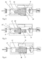
- eine schematische Darstellung einer Ansteuerung einer Kupplung mit integriertem Ausgleichsbehälter und gemeinsamem Ölkreislauf,
- Fig. 2
- eine schematische Darstellung einer Ansteuerung einer Kupplung mit einem Geberzylinder mit gestuftem Geberkolben,
- Fig. 3
- eine schematische Darstellung einer Ansteuerung einer Kupplung mit einem Geberzylinder mit Geberkolben und vorgelagertem Pilotkolben,
- Fig. 4
- eine schematische Darstellung einer Ansteuerung einer Kupplung mit einem Ringkanal im Geberzylinder und
- Fig. 5
- eine schematische Darstellung einer Ansteuerung einer Kupplung mit einem Geberzylinder und einer in einer umlaufenden Nut der Geberzylinderwandung angeordneter Dichtung.
- Fig. 1
- a schematic representation of a control of a clutch with integrated reservoir and common oil circuit,
- Fig. 2
- a schematic representation of a control of a clutch with a master cylinder with stepped master piston,
- Fig. 3
- a schematic representation of a control of a clutch with a master cylinder with master piston and upstream pilot piston,
- Fig. 4
- a schematic representation of a control of a clutch with an annular channel in the master cylinder and
- Fig. 5
- a schematic representation of a control of a clutch with a master cylinder and arranged in a circumferential groove of the master cylinder wall seal.
Die Ansteuerung 1 einer Kupplung besteht im Wesentlichen aus einer Ansteuereinheit 2, einer hydraulischen Steuerung 3, einem Steuergerät 4 und einem Nehmerzylinder 5 zur Betätigung einer Kupplung.The control 1 of a clutch consists essentially of a
Die Ansteuereinheit 2 besteht aus einem Geberzylinder 6, dessen Innenraum von einem längs verschieblichen Geberkolben in einen Nehmerölraum 8 und einen Geberölraum 9 unterteilt wird. Im Geberölraum 9 ist eine Druckfeder 10 angeordnet, die den Geberkolben 7 im drucklosen Zustand in seine Ausgangsstellung im Nehmerölraum 8 drückt. In der Ausgangsstellung des Geberkolbens 7 ist der Geberölraum über eine Ausgleichsleitung 11 mit einem Ausgleichsbehälter 12 verbunden. Der Geberkolben 7 weist zum Nehmerölraum 8 und zum Geberölraum 9 hin jeweils ein Ringnut 13, 14 auf, in der jeweils eine Dichtung 15, 16 zur Abdichtung gegenüber der dem Kolben benachbarten Zylinderinnenwandung 17 angeordnet ist. Neben dem Geberzylinder 6 und dem Ausgleichsbehälter 12 ist in der Ansteuereinheit 2 ein Ventil 18 angeordnet. Das Ventil 18 verbindet in einer ersten Stellung den Nehmerölraum 8 über eine Rückleitung 19 mit dem Ausgleichsbehälter 12.The
Der Ausgleichsbehälter 12 weist ein Ausgleichsvolumen 20 auf, das an seinem höchsten Punkt einen Überlauf 21 aufweist, der über einen Tankanschluss 22 mit der Tankleitung 23 zu einem Ölreservoir 24 der hydraulischen Steuerung 3 verbunden ist. In einer zweiten Stellung verbindet das Ventil 18 eine von dem Ölreservoir 24 bzw. der hydraulischen Steuerung 3 gespeiste Druckleitung 26 über einen externen Druckanschluss 27 der Ansteuereinheit 2 mit dem Nehmerölraum 8. Das Ventil 18 wird von einer Ventilansteuerung 28, die über einen externen Ventilsteueranschluss 29 der Ansteuereinheit 2 mit dem Steuergerät 4 über eine Steuerleitung 30 verbunden ist, gesteuert.The
Der Geberölraum 9 ist über einen externen Arbeitsanschluss 31 der Ansteuereinheit 2 mit einer zu einem Ölraum 32 des Nehmerzylinders 5 führenden Arbeitsleitung 33 verbunden.The
Bei einem Rückhub des Geberkolbens 7 wird das Ansteuerölvolumen vom Nehmerölraum 8 in der ersten Ventilstellung des Ventils 18 über die Rückleitung 19 in den Ausgleichsbehälter 12 geleitet. Dabei wird das Ausgleichsvolumen 20 aufgefüllt und überschüssiges Öl über den Überlauf 21 und die Tankleitung 23 in das Ölreservoir 24 der hydraulischen Steuerung 3 geleitet. Das Ausgleichsvolumen 20 bzw. der Ausgleichsbehälter 12 wird also mit jeder Betätigung des Geberkolbens 7 nachgefüllt. Über die Ausgleichsleitung 11 ist dabei eine Betriebsentlüftung der Kupplungsbetätigungsstrecke gewährleistet. Ein hinreichend großer Querschnitt der Ausgleichsleitung 11 als Verbindung zwischen Ausgleichsvolumen 20 und Geberölraum 9 gewährleistet die Funktion der selbstständigen Erst- und Wiederbefüllung durch mehrmalige Betätigung. Die Größe des Querschnitts der hydraulischen Verbindung bzw. der Ausgleichsleitung 11 ist dabei so gewählt, dass das Öl unerzwungen vom Ausgleichsvolumen 20 des Ausgleichsbehälters 12 in den Geberölraum 9 fließen kann.In a return stroke of the
Der Vorgang der Befüllung beginnt bei vollständig leerer Kupplungsbetätigungsstrecke mit der Ansteuerung des Geberkolbens 7 durch die hydraulische Steuerung 3. Im Rückhub des Geberkolbens 7 wird das Ansteuerölvolumen vom Nehmerölraum 8 in das Ausgleichsvolumen 20 verschoben und fließt in der Endlage des Geberkolbens 7 durch die Ausgleichsleitung 11 in den Geberölraum 9. Durch die nächste Betätigung wird das in den Geberölraum 9 gelaufene Öl in den Nehmerzylinder 5 verschoben. Der Nehmerzylinder 5 wird hierdurch teilweise mit Öl befüllt. Da sich die Ansteuereinheit 2 am höchsten Punkt des hydraulischen Systems befindet, wird im Rückhub Luft aus dem Nehmerzylinder 5 in den Geberölraum 9 des Geberzylinders 6 verschoben. Gleichzeitig wird wiederum das Ansteueröl vom Nehmerölraum 8 des Geberzylinders 6 in das Ausgleichsvolumen 20 bzw. den Ausgleichsbehälter 12 verschoben und fließt von hier in den Geberölraum 9. Es folgen weitere Betätigungen in geeigneter Anzahl bis der Nehmerzylinder 5 auf die oben beschriebene Weise vollständig befüllt, sowie der Geberölraum 9 entlüftet und der Ausgleichsbehälter 12 vollständig gefüllt ist. Durch die Anbindung des Ausgleichsvolumens 20 an den externen Tankanschluss 22 ist ebenso die Nachstellung der nicht dargestellten Kupplung mit zunehmendem Verschleiß gegeben. Durch Verschleiß des Kupplungsbelages kann die Kupplung zunehmend weiter einrücken als im Neuzustand. Hierdurch entsteht ein Differenzölvolumen, das aus dem Nehmerzylinder 5 herausgefördert werden muss, um die Kupplung vollständig zu schließen. Der Geberkolben 7 nimmt beim Rückhub das durch Kolbendurchmesser und Hub definierte Betätigungsölvolumen auf, das Differenzölvolumen entweicht nach Freigabe der hydraulischen Verbindung in das Ausgleichsvolumen 20 und von dort über den Überlauf 21 in das Ölreservoir 24 der hydraulischen Steuerung 3.In the return stroke of the
Entsprechend dem Ausführungsbeispiel von
Nach dem Ausführungsbeispiel von
Gemäß dem Ausführungsbeispiel von
Entsprechend dem Ausführungsbeispiel von
- 11
- Ansteuerungcontrol
- 22
- Ansteuereinheitcontrol unit
- 33
- Hydraulische SteuerungHydraulic control
- 44
- Steuergerätcontrol unit
- 55
- Nehmerzylinderslave cylinder
- 6, 6', 6", 6"', 6""6, 6 ', 6 ", 6"', 6 ""
- GeberzylinderMaster cylinder
- 7', 7', 7", 7""7 ', 7', 7 ", 7" "
- Geberkolben v. 6Master piston v. 6
- 8, 8', 8"8, 8 ', 8 "
- Nehmerölraum v. 6Slave oil room v. 6
- 9, 9', 9", 9"', 9""9, 9 ', 9 ", 9"', 9 ""
- Geberölraum v. 6Donor oil room v. 6
- 1010
- Druckfedercompression spring
- 1111
- Ausgleichsleitungcompensation line
- 1212
- Ausgleichsbehältersurge tank
- 1313
- Ringnutring groove
- 1414
- Ringnutring groove
- 1515
- Dichtungpoetry
- 1616
- Dichtungpoetry
- 17, 17""17, 17 ""
- ZylinderinhenwandungZylinderinhenwandung
- 1818
- VentilValve
- 1919
- Rückleitungreturn
- 2020
- Ausgleichsvolumencompensating volume
- 2121
- Überlauf v. 20/12Overflow v. 20/12
- 2222
- Tankanschluss v. 2Tank connection v. 2
- 2323
- Tankleitungtank line
- 2424
- Ölreservoiroil reservoir
- 2525
- Pumpepump
- 2626
- Druckleitungpressure line
- 2727
- ext. Druckanschluss v. 2ext. Pressure connection v. 2
- 2828
- Ventilansteuerungvalve control
- 2929
- Ventilsteueranschluss v. 2Valve control port v. 2
- 3030
- Steuerleitungcontrol line
- 3131
- Arbeitsanschluss v. 2Work connection v. 2
- 3232
- Ölraum v. 5Oil room v. 5
- 3333
- Arbeitsleitungworking line
- 34, 34', 34"34, 34 ', 34 "
- nehmerseitige Kolbenflächeslave side piston surface
- 35, 35', 35"35, 35 ', 35 "
- geberseitige Kolbenflächeencoder-side piston surface
- 36, 36', 36"36, 36 ', 36 "
- geberseitige Kolbenflächeencoder-side piston surface
- 3737
- Pilotkolbenpilot piston
- 3838
- Ringkanalannular channel
- 3939
- Ringnut v. 6""Ring groove v. 6 ""
- 4040
- Dichtungpoetry
- 4141
- Abflachungflattening
Claims (10)
- Actuation means for a clutch, in particular for a hybrid drive, having a master cylinder (6, 6', 6", 6"', 6"") whose interior space is divided by a master piston (7, 7', 7", 7"', 7"") into a slave oil chamber (8, 8") and a master oil chamber (9, 9"', 9""), with the slave oil chamber (8, 8") being connected by means of a valve (18) to a tank line (23) to an oil reservoir (24) in a first valve position and to a pressure line (26) from the oil reservoir (24) in a second valve position, and with the master oil chamber (9, 9', 9", 9"', 9"") being connected via a working line (33) to the oil chamber (32) of a slave cylinder (5) and via a compensating line (11), as a function of the position of the master piston (7, 7', 7", 7"', 7""), to a compensating tank (12),
characterized
in that the valve (18), in its first position, connects the slave oil chamber (8, 8") via a return line (19) to the compensating tank (12) and
in that the compensating tank (12) has a compensating volume (20) which, at its highest point, has an overflow (21) which is connected to the tank line (23). - Actuation means according to in Claim 1, characterized in that the master cylinder (6, 6', 6", 6"', 6""), the compensating tank (12) and the valve (18) are arranged in a housing and form an actuation unit (2).
- Actuation means according to in Claim 2, characterized in that the actuation unit (2) has an external working connection (31) for connecting to the slave cylinder (5), an external tank connection (22) and an external pressure connection (27) for connecting to the oil reservoir (24), and a valve control connection (29) for connecting a control unit (4) to a valve actuation means (28) of the valve (18).
- Actuation means according to in one of Claims 1 to 3, characterized in that, when an equal pressure level prevails on both sides of the master cylinder (6, 6"', 6""), the master piston (7, 7"', 7"") has equal-sized hydraulically acting piston surfaces (34, 35, 36) pointing toward the slave oil chamber (8) and toward the master oil chamber (9 9"', 9"").
- Actuation means according to in one of Claims 1 to 3, characterized in that the master piston (7', 7") has different-sized hydraulically acting piston surfaces (34', 34") pointing toward the slave oil chamber (8', 8") and toward the master oil chamber (9' 9").
- Actuation means according to in one of Claims 1 to 5, characterized in that, between the master piston (7, 7', 7", 7"', 7"") and master cylinder (6, 6', 6", 6"', 6""), a seal (15, 16, 40) is arranged in an annular groove (13, 14, 39) in such a way that, in an end position of the master piston (7, 7', 7", 7"', 7"") when the slave oil chamber (8, 8', 8") is empty, the opening of the compensating line (11) to the master oil chamber (9, 9', 9", 9"', 9"") is exposed, with a passage which connects the master oil chamber (9, 9', 9", 9"', 9"") to the opening of the compensating line (11) being formed in a region, which is situated upstream of the seal (15, 16, 40) in the direction of the master oil chamber (9, 9', 9", 9"', 9""), between the piston circumference and the adjacent cylinder inner wall (17).
- Actuation means according to in Claim 6, characterized in that the seal (15, 16) is arranged in an encircling groove of the master piston (7, 7', 7", 7"').
- Actuation means according to in Claim 6, characterized in that the seal (40) is arranged in an encircling groove of the cylinder wall (17"").
- Method for actuating a clutch, in particular for a hybrid drive, in which method, to activate a working piston in a slave cylinder (5) which is assigned to a clutch, a slave oil chamber (8, 8', 8") of a master cylinder (6, 6', 6", 6"', 6"") is filled with oil via a valve (18) which connects the slave oil chamber (8, 8', 8") to a pressure line (26) of an oil reservoir (24), with the oil being pressed from a master oil chamber (9, 9', 9", 9"', 9"") of the master cylinder (6, 6', 6", 6"', 6"") via a working line (33) into an oil chamber (23) of the slave cylinder (5), and moving the working piston into its activating position, as a result of a movement of a master piston (7, 7', 7", 7"', 7""), wherein in order to restore the working piston, the slave oil chamber (8, 8', 8") of the master cylinder (6, 6', 6", 6"', 6"") is separated from the pressure line (26) and connected to a tank line (23) by means of the valve (18) and is emptied, wherein in the initial position of the master piston (7, 7', 7", 7"', 7""), the master oil chamber (9, 9', 9", 9"', 9"") is ventilated via a compensating tank (12) and a lack of oil volume is compensated,
characterized
in that the slave oil chamber (8, 8', 8"), in order to be emptied, is connected by means of the valve (18) to the compensating tank (12) and the latter is filled, with excess oil being supplied back to the oil reservoir (24) via an overflow (21) of the compensating tank (12) via the tank line (23) which is connected to the overflow (21). - Method according to in Claim 9, characterized in that, in the event of the clutch activation path being completely empty, the master cylinder (6, 6', 6", 6"', 6"") is actuated repeatedly in order to completely fill the master oil chamber (9, 9', 9", 9"', 9"") and compensating tank (12).
Applications Claiming Priority (2)
| Application Number | Priority Date | Filing Date | Title |
|---|---|---|---|
| DE102007045056A DE102007045056A1 (en) | 2007-09-20 | 2007-09-20 | Control of a clutch |
| PCT/EP2008/006675 WO2009039918A1 (en) | 2007-09-20 | 2008-08-14 | Actuation means for a clutch |
Publications (2)
| Publication Number | Publication Date |
|---|---|
| EP2191158A1 EP2191158A1 (en) | 2010-06-02 |
| EP2191158B1 true EP2191158B1 (en) | 2011-04-13 |
Family
ID=39967985
Family Applications (1)
| Application Number | Title | Priority Date | Filing Date |
|---|---|---|---|
| EP08801575A Not-in-force EP2191158B1 (en) | 2007-09-20 | 2008-08-14 | Actuation means for a clutch |
Country Status (6)
| Country | Link |
|---|---|
| US (1) | US8376113B2 (en) |
| EP (1) | EP2191158B1 (en) |
| CN (1) | CN101802432B (en) |
| AT (1) | ATE505664T1 (en) |
| DE (2) | DE102007045056A1 (en) |
| WO (1) | WO2009039918A1 (en) |
Families Citing this family (6)
| Publication number | Priority date | Publication date | Assignee | Title |
|---|---|---|---|---|
| CN103671628B (en) * | 2012-09-18 | 2016-04-13 | 广西玉柴机器股份有限公司 | Electronic control automatic clutch drive mechanism |
| EP2917602B1 (en) * | 2012-11-12 | 2020-09-23 | Schaeffler Technologies AG & Co. KG | Hydraulic line between a master cylinder and a slave cylinder, in particular in the form of a release mechanism secured to the cover, and a pressure intensifier |
| CN103851105B (en) * | 2012-12-07 | 2016-05-18 | 上海汽车集团股份有限公司 | A kind of hydraulic clutch release system |
| DE102014215926B3 (en) * | 2014-08-12 | 2015-06-18 | Schaeffler Technologies AG & Co. KG | Hydrostatic clutch actuator with overflow |
| CN106321684B (en) * | 2015-06-26 | 2018-11-20 | 上海汽车集团股份有限公司 | Clutch control, clutch system, automobile and its electronic control unit |
| US20170130748A1 (en) * | 2015-11-05 | 2017-05-11 | Borgwarner Inc. | Multi-output charging device |
Family Cites Families (13)
| Publication number | Priority date | Publication date | Assignee | Title |
|---|---|---|---|---|
| US2158440A (en) * | 1936-07-31 | 1939-05-16 | W C Lipe Inc | Friction clutch mechanism |
| DE3732427A1 (en) * | 1987-09-25 | 1989-04-13 | Daimler Benz Ag | Device for the suppression of longitudinal vibrations on a vehicle with shift transmission |
| SE460919B (en) * | 1988-04-22 | 1989-12-04 | Kongsberg Automotive As | ARRANGEMENTS FOR REGULATION OF A HYDRAULIC MANOVERED LAMEL COUPLING WITH SOLAR SPRING |
| IT1233591B (en) | 1989-05-26 | 1992-04-06 | Iveco Fiat | ACTUATOR DEVICE IN PARTICULAR FOR ACTIVATING THE CLUTCH IN A MOTOR VEHICLE CLUTCH |
| GB2249815B (en) * | 1990-02-24 | 1993-10-06 | Automotive Products Plc | A clutch control system |
| DE4309901B4 (en) | 1992-11-10 | 2010-07-01 | Zf Sachs Ag | Hydraulic actuator - especially for a motor vehicle friction clutch |
| US5795263A (en) | 1994-03-29 | 1998-08-18 | Kongsberg Techmatic Uk Limited | Actuation systems and mechanisms |
| WO1995026472A1 (en) * | 1994-03-29 | 1995-10-05 | Automotive Products Plc | Actuation systems and mechanisms |
| DE19542766B4 (en) * | 1994-11-25 | 2004-11-04 | Volkswagen Ag | working cylinder |
| US5850898A (en) * | 1995-09-15 | 1998-12-22 | Fahrzeugtechnik Ebern Gmbh | Method and device for the hydraulic actuation of a clutch, especially for automobiles |
| DE19633420A1 (en) | 1995-09-15 | 1997-03-20 | Ebern Fahrzeugtech Gmbh | Clutch control system particularly for motor vehicle |
| JP3940266B2 (en) * | 2001-01-22 | 2007-07-04 | 株式会社エクセディ | Hydraulic mechanism for clutch operating system |
| DE102004007160A1 (en) * | 2004-02-12 | 2005-08-25 | Volkswagen Ag | Process to achieve smooth automotive acceleration while changing gear by regulation of clutch speed within a defined range |
-
2007
- 2007-09-20 DE DE102007045056A patent/DE102007045056A1/en not_active Withdrawn
-
2008
- 2008-08-14 EP EP08801575A patent/EP2191158B1/en not_active Not-in-force
- 2008-08-14 AT AT08801575T patent/ATE505664T1/en active
- 2008-08-14 US US12/679,340 patent/US8376113B2/en not_active Expired - Fee Related
- 2008-08-14 WO PCT/EP2008/006675 patent/WO2009039918A1/en active Application Filing
- 2008-08-14 DE DE502008003197T patent/DE502008003197D1/en active Active
- 2008-08-14 CN CN2008801086093A patent/CN101802432B/en not_active Expired - Fee Related
Also Published As
| Publication number | Publication date |
|---|---|
| WO2009039918A1 (en) | 2009-04-02 |
| DE502008003197D1 (en) | 2011-05-26 |
| US20100193316A1 (en) | 2010-08-05 |
| US8376113B2 (en) | 2013-02-19 |
| EP2191158A1 (en) | 2010-06-02 |
| CN101802432B (en) | 2012-12-12 |
| ATE505664T1 (en) | 2011-04-15 |
| DE102007045056A1 (en) | 2009-04-02 |
| CN101802432A (en) | 2010-08-11 |
Similar Documents
| Publication | Publication Date | Title |
|---|---|---|
| EP2609348B1 (en) | Hydraulic control for an automatic transmission of a motor vehicle | |
| WO2017016849A1 (en) | Parking brake system | |
| DE102006038446B4 (en) | Manual transmission having at least one driven piston-cylinder unit, and a method for operating the gearbox | |
| EP2191158B1 (en) | Actuation means for a clutch | |
| DE102014209856A1 (en) | Hydraulic supply device | |
| DE102014018123A1 (en) | Parking lock device | |
| DE102011109376A1 (en) | Hydraulic control for an automatic transmission of a motor vehicle | |
| DE102011109377A1 (en) | Hydraulic control for an automatic transmission of a motor vehicle | |
| EP3224495B1 (en) | Clutch actuation device | |
| DE102013001928A1 (en) | Motor vehicle transmission device with a hydraulic system | |
| DE102011100800A1 (en) | Clutch transmission, method of operation | |
| DE102014224201A1 (en) | Hydrostatic clutch actuator | |
| DE102015211305B3 (en) | Pressure-dependent insertable parking brake for hydraulic manual transmission | |
| DE102011082820A1 (en) | Clutch actuating system, has master cylinder and slave cylinder that are connected by hydraulic line, where slave cylinder comprises exhaust port that is designed and dimensioned such that exhaust port allows air | |
| WO2017125108A1 (en) | Hydraulic switching assembly for a motor vehicle | |
| DE102018208755A1 (en) | Pressure control valve | |
| DE102007032042A1 (en) | Clutch system with hydraulically actuated clutch device | |
| DE102015215930A1 (en) | Hydraulic system of an automatic transmission | |
| DE102018214433A1 (en) | Hydraulic system for a transmission of a motor vehicle drive train | |
| DE102014118446A1 (en) | Circuit for controlling hydraulic pressure of a torque converter | |
| DE2161234A1 (en) | Control device | |
| DE102019202617B4 (en) | Shift element for an automatic transmission and method for its operation | |
| EP0470950B1 (en) | Device for electrohydraulic actuator of a clutch which locks the transfer differential of a vehicle | |
| EP2085634B1 (en) | Hydraulic actuation system for a motor vehicle with two pressure lines | |
| DE102009018793A1 (en) | transmission device |
Legal Events
| Date | Code | Title | Description |
|---|---|---|---|
| PUAI | Public reference made under article 153(3) epc to a published international application that has entered the european phase |
Free format text: ORIGINAL CODE: 0009012 |
|
| 17P | Request for examination filed |
Effective date: 20100420 |
|
| AK | Designated contracting states |
Kind code of ref document: A1 Designated state(s): AT BE BG CH CY CZ DE DK EE ES FI FR GB GR HR HU IE IS IT LI LT LU LV MC MT NL NO PL PT RO SE SI SK TR |
|
| AX | Request for extension of the european patent |
Extension state: AL BA MK RS |
|
| GRAP | Despatch of communication of intention to grant a patent |
Free format text: ORIGINAL CODE: EPIDOSNIGR1 |
|
| DAX | Request for extension of the european patent (deleted) | ||
| GRAS | Grant fee paid |
Free format text: ORIGINAL CODE: EPIDOSNIGR3 |
|
| GRAA | (expected) grant |
Free format text: ORIGINAL CODE: 0009210 |
|
| AK | Designated contracting states |
Kind code of ref document: B1 Designated state(s): AT BE BG CH CY CZ DE DK EE ES FI FR GB GR HR HU IE IS IT LI LT LU LV MC MT NL NO PL PT RO SE SI SK TR |
|
| REG | Reference to a national code |
Ref country code: GB Ref legal event code: FG4D Free format text: NOT ENGLISH |
|
| REG | Reference to a national code |
Ref country code: CH Ref legal event code: EP |
|
| REG | Reference to a national code |
Ref country code: IE Ref legal event code: FG4D Free format text: LANGUAGE OF EP DOCUMENT: GERMAN |
|
| REF | Corresponds to: |
Ref document number: 502008003197 Country of ref document: DE Date of ref document: 20110526 Kind code of ref document: P |
|
| REG | Reference to a national code |
Ref country code: DE Ref legal event code: R096 Ref document number: 502008003197 Country of ref document: DE Effective date: 20110526 |
|
| REG | Reference to a national code |
Ref country code: NL Ref legal event code: VDEP Effective date: 20110413 |
|
| LTIE | Lt: invalidation of european patent or patent extension |
Effective date: 20110413 |
|
| PG25 | Lapsed in a contracting state [announced via postgrant information from national office to epo] |
Ref country code: LT Free format text: LAPSE BECAUSE OF FAILURE TO SUBMIT A TRANSLATION OF THE DESCRIPTION OR TO PAY THE FEE WITHIN THE PRESCRIBED TIME-LIMIT Effective date: 20110413 Ref country code: NO Free format text: LAPSE BECAUSE OF FAILURE TO SUBMIT A TRANSLATION OF THE DESCRIPTION OR TO PAY THE FEE WITHIN THE PRESCRIBED TIME-LIMIT Effective date: 20110713 Ref country code: SE Free format text: LAPSE BECAUSE OF FAILURE TO SUBMIT A TRANSLATION OF THE DESCRIPTION OR TO PAY THE FEE WITHIN THE PRESCRIBED TIME-LIMIT Effective date: 20110413 Ref country code: PT Free format text: LAPSE BECAUSE OF FAILURE TO SUBMIT A TRANSLATION OF THE DESCRIPTION OR TO PAY THE FEE WITHIN THE PRESCRIBED TIME-LIMIT Effective date: 20110816 Ref country code: HR Free format text: LAPSE BECAUSE OF FAILURE TO SUBMIT A TRANSLATION OF THE DESCRIPTION OR TO PAY THE FEE WITHIN THE PRESCRIBED TIME-LIMIT Effective date: 20110413 |
|
| REG | Reference to a national code |
Ref country code: IE Ref legal event code: FD4D |
|
| PG25 | Lapsed in a contracting state [announced via postgrant information from national office to epo] |
Ref country code: SI Free format text: LAPSE BECAUSE OF FAILURE TO SUBMIT A TRANSLATION OF THE DESCRIPTION OR TO PAY THE FEE WITHIN THE PRESCRIBED TIME-LIMIT Effective date: 20110413 Ref country code: ES Free format text: LAPSE BECAUSE OF FAILURE TO SUBMIT A TRANSLATION OF THE DESCRIPTION OR TO PAY THE FEE WITHIN THE PRESCRIBED TIME-LIMIT Effective date: 20110724 Ref country code: FI Free format text: LAPSE BECAUSE OF FAILURE TO SUBMIT A TRANSLATION OF THE DESCRIPTION OR TO PAY THE FEE WITHIN THE PRESCRIBED TIME-LIMIT Effective date: 20110413 Ref country code: GR Free format text: LAPSE BECAUSE OF FAILURE TO SUBMIT A TRANSLATION OF THE DESCRIPTION OR TO PAY THE FEE WITHIN THE PRESCRIBED TIME-LIMIT Effective date: 20110714 Ref country code: IS Free format text: LAPSE BECAUSE OF FAILURE TO SUBMIT A TRANSLATION OF THE DESCRIPTION OR TO PAY THE FEE WITHIN THE PRESCRIBED TIME-LIMIT Effective date: 20110813 Ref country code: LV Free format text: LAPSE BECAUSE OF FAILURE TO SUBMIT A TRANSLATION OF THE DESCRIPTION OR TO PAY THE FEE WITHIN THE PRESCRIBED TIME-LIMIT Effective date: 20110413 Ref country code: CY Free format text: LAPSE BECAUSE OF FAILURE TO SUBMIT A TRANSLATION OF THE DESCRIPTION OR TO PAY THE FEE WITHIN THE PRESCRIBED TIME-LIMIT Effective date: 20110413 |
|
| PG25 | Lapsed in a contracting state [announced via postgrant information from national office to epo] |
Ref country code: NL Free format text: LAPSE BECAUSE OF FAILURE TO SUBMIT A TRANSLATION OF THE DESCRIPTION OR TO PAY THE FEE WITHIN THE PRESCRIBED TIME-LIMIT Effective date: 20110413 Ref country code: MT Free format text: LAPSE BECAUSE OF FAILURE TO SUBMIT A TRANSLATION OF THE DESCRIPTION OR TO PAY THE FEE WITHIN THE PRESCRIBED TIME-LIMIT Effective date: 20110413 |
|
| PG25 | Lapsed in a contracting state [announced via postgrant information from national office to epo] |
Ref country code: EE Free format text: LAPSE BECAUSE OF FAILURE TO SUBMIT A TRANSLATION OF THE DESCRIPTION OR TO PAY THE FEE WITHIN THE PRESCRIBED TIME-LIMIT Effective date: 20110413 Ref country code: CZ Free format text: LAPSE BECAUSE OF FAILURE TO SUBMIT A TRANSLATION OF THE DESCRIPTION OR TO PAY THE FEE WITHIN THE PRESCRIBED TIME-LIMIT Effective date: 20110413 Ref country code: IE Free format text: LAPSE BECAUSE OF FAILURE TO SUBMIT A TRANSLATION OF THE DESCRIPTION OR TO PAY THE FEE WITHIN THE PRESCRIBED TIME-LIMIT Effective date: 20110413 |
|
| PLBE | No opposition filed within time limit |
Free format text: ORIGINAL CODE: 0009261 |
|
| STAA | Information on the status of an ep patent application or granted ep patent |
Free format text: STATUS: NO OPPOSITION FILED WITHIN TIME LIMIT |
|
| BERE | Be: lapsed |
Owner name: VOLKSWAGEN A.G. Effective date: 20110831 |
|
| PG25 | Lapsed in a contracting state [announced via postgrant information from national office to epo] |
Ref country code: RO Free format text: LAPSE BECAUSE OF FAILURE TO SUBMIT A TRANSLATION OF THE DESCRIPTION OR TO PAY THE FEE WITHIN THE PRESCRIBED TIME-LIMIT Effective date: 20110413 Ref country code: DK Free format text: LAPSE BECAUSE OF FAILURE TO SUBMIT A TRANSLATION OF THE DESCRIPTION OR TO PAY THE FEE WITHIN THE PRESCRIBED TIME-LIMIT Effective date: 20110413 Ref country code: PL Free format text: LAPSE BECAUSE OF FAILURE TO SUBMIT A TRANSLATION OF THE DESCRIPTION OR TO PAY THE FEE WITHIN THE PRESCRIBED TIME-LIMIT Effective date: 20110413 Ref country code: SK Free format text: LAPSE BECAUSE OF FAILURE TO SUBMIT A TRANSLATION OF THE DESCRIPTION OR TO PAY THE FEE WITHIN THE PRESCRIBED TIME-LIMIT Effective date: 20110413 |
|
| 26N | No opposition filed |
Effective date: 20120116 |
|
| PG25 | Lapsed in a contracting state [announced via postgrant information from national office to epo] |
Ref country code: MC Free format text: LAPSE BECAUSE OF NON-PAYMENT OF DUE FEES Effective date: 20110831 |
|
| REG | Reference to a national code |
Ref country code: DE Ref legal event code: R097 Ref document number: 502008003197 Country of ref document: DE Effective date: 20120116 |
|
| PG25 | Lapsed in a contracting state [announced via postgrant information from national office to epo] |
Ref country code: IT Free format text: LAPSE BECAUSE OF FAILURE TO SUBMIT A TRANSLATION OF THE DESCRIPTION OR TO PAY THE FEE WITHIN THE PRESCRIBED TIME-LIMIT Effective date: 20110413 Ref country code: BE Free format text: LAPSE BECAUSE OF NON-PAYMENT OF DUE FEES Effective date: 20110831 |
|
| REG | Reference to a national code |
Ref country code: CH Ref legal event code: PL |
|
| PG25 | Lapsed in a contracting state [announced via postgrant information from national office to epo] |
Ref country code: CH Free format text: LAPSE BECAUSE OF NON-PAYMENT OF DUE FEES Effective date: 20120831 Ref country code: LI Free format text: LAPSE BECAUSE OF NON-PAYMENT OF DUE FEES Effective date: 20120831 |
|
| PG25 | Lapsed in a contracting state [announced via postgrant information from national office to epo] |
Ref country code: LU Free format text: LAPSE BECAUSE OF NON-PAYMENT OF DUE FEES Effective date: 20110814 |
|
| PG25 | Lapsed in a contracting state [announced via postgrant information from national office to epo] |
Ref country code: BG Free format text: LAPSE BECAUSE OF FAILURE TO SUBMIT A TRANSLATION OF THE DESCRIPTION OR TO PAY THE FEE WITHIN THE PRESCRIBED TIME-LIMIT Effective date: 20110713 |
|
| PG25 | Lapsed in a contracting state [announced via postgrant information from national office to epo] |
Ref country code: TR Free format text: LAPSE BECAUSE OF FAILURE TO SUBMIT A TRANSLATION OF THE DESCRIPTION OR TO PAY THE FEE WITHIN THE PRESCRIBED TIME-LIMIT Effective date: 20110413 |
|
| PG25 | Lapsed in a contracting state [announced via postgrant information from national office to epo] |
Ref country code: HU Free format text: LAPSE BECAUSE OF FAILURE TO SUBMIT A TRANSLATION OF THE DESCRIPTION OR TO PAY THE FEE WITHIN THE PRESCRIBED TIME-LIMIT Effective date: 20110413 |
|
| REG | Reference to a national code |
Ref country code: AT Ref legal event code: MM01 Ref document number: 505664 Country of ref document: AT Kind code of ref document: T Effective date: 20130814 |
|
| PG25 | Lapsed in a contracting state [announced via postgrant information from national office to epo] |
Ref country code: AT Free format text: LAPSE BECAUSE OF NON-PAYMENT OF DUE FEES Effective date: 20130814 |
|
| REG | Reference to a national code |
Ref country code: FR Ref legal event code: PLFP Year of fee payment: 8 |
|
| REG | Reference to a national code |
Ref country code: FR Ref legal event code: PLFP Year of fee payment: 9 |
|
| REG | Reference to a national code |
Ref country code: FR Ref legal event code: PLFP Year of fee payment: 10 |
|
| REG | Reference to a national code |
Ref country code: FR Ref legal event code: PLFP Year of fee payment: 11 |
|
| PGFP | Annual fee paid to national office [announced via postgrant information from national office to epo] |
Ref country code: DE Payment date: 20190831 Year of fee payment: 12 Ref country code: FR Payment date: 20190827 Year of fee payment: 12 |
|
| PGFP | Annual fee paid to national office [announced via postgrant information from national office to epo] |
Ref country code: GB Payment date: 20190829 Year of fee payment: 12 |
|
| REG | Reference to a national code |
Ref country code: DE Ref legal event code: R119 Ref document number: 502008003197 Country of ref document: DE |
|
| GBPC | Gb: european patent ceased through non-payment of renewal fee |
Effective date: 20200814 |
|
| PG25 | Lapsed in a contracting state [announced via postgrant information from national office to epo] |
Ref country code: DE Free format text: LAPSE BECAUSE OF NON-PAYMENT OF DUE FEES Effective date: 20210302 Ref country code: FR Free format text: LAPSE BECAUSE OF NON-PAYMENT OF DUE FEES Effective date: 20200831 |
|
| PG25 | Lapsed in a contracting state [announced via postgrant information from national office to epo] |
Ref country code: GB Free format text: LAPSE BECAUSE OF NON-PAYMENT OF DUE FEES Effective date: 20200814 |