EP2191154B1 - Roller bearing for components which can be displaced axially in relation to one another, in particular for shift elements of gearboxes - Google Patents
Roller bearing for components which can be displaced axially in relation to one another, in particular for shift elements of gearboxes Download PDFInfo
- Publication number
- EP2191154B1 EP2191154B1 EP08787112A EP08787112A EP2191154B1 EP 2191154 B1 EP2191154 B1 EP 2191154B1 EP 08787112 A EP08787112 A EP 08787112A EP 08787112 A EP08787112 A EP 08787112A EP 2191154 B1 EP2191154 B1 EP 2191154B1
- Authority
- EP
- European Patent Office
- Prior art keywords
- rolling bodies
- friction bearing
- bearing according
- raceways
- components
- Prior art date
- Legal status (The legal status is an assumption and is not a legal conclusion. Google has not performed a legal analysis and makes no representation as to the accuracy of the status listed.)
- Not-in-force
Links
Images


Classifications
-
- F—MECHANICAL ENGINEERING; LIGHTING; HEATING; WEAPONS; BLASTING
- F16—ENGINEERING ELEMENTS AND UNITS; GENERAL MEASURES FOR PRODUCING AND MAINTAINING EFFECTIVE FUNCTIONING OF MACHINES OR INSTALLATIONS; THERMAL INSULATION IN GENERAL
- F16H—GEARING
- F16H63/00—Control outputs from the control unit to change-speed- or reversing-gearings for conveying rotary motion or to other devices than the final output mechanism
- F16H63/02—Final output mechanisms therefor; Actuating means for the final output mechanisms
- F16H63/30—Constructional features of the final output mechanisms
-
- F—MECHANICAL ENGINEERING; LIGHTING; HEATING; WEAPONS; BLASTING
- F16—ENGINEERING ELEMENTS AND UNITS; GENERAL MEASURES FOR PRODUCING AND MAINTAINING EFFECTIVE FUNCTIONING OF MACHINES OR INSTALLATIONS; THERMAL INSULATION IN GENERAL
- F16C—SHAFTS; FLEXIBLE SHAFTS; ELEMENTS OR CRANKSHAFT MECHANISMS; ROTARY BODIES OTHER THAN GEARING ELEMENTS; BEARINGS
- F16C29/00—Bearings for parts moving only linearly
- F16C29/002—Elastic or yielding linear bearings or bearing supports
-
- F—MECHANICAL ENGINEERING; LIGHTING; HEATING; WEAPONS; BLASTING
- F16—ENGINEERING ELEMENTS AND UNITS; GENERAL MEASURES FOR PRODUCING AND MAINTAINING EFFECTIVE FUNCTIONING OF MACHINES OR INSTALLATIONS; THERMAL INSULATION IN GENERAL
- F16C—SHAFTS; FLEXIBLE SHAFTS; ELEMENTS OR CRANKSHAFT MECHANISMS; ROTARY BODIES OTHER THAN GEARING ELEMENTS; BEARINGS
- F16C29/00—Bearings for parts moving only linearly
- F16C29/04—Ball or roller bearings
-
- F—MECHANICAL ENGINEERING; LIGHTING; HEATING; WEAPONS; BLASTING
- F16—ENGINEERING ELEMENTS AND UNITS; GENERAL MEASURES FOR PRODUCING AND MAINTAINING EFFECTIVE FUNCTIONING OF MACHINES OR INSTALLATIONS; THERMAL INSULATION IN GENERAL
- F16H—GEARING
- F16H63/00—Control outputs from the control unit to change-speed- or reversing-gearings for conveying rotary motion or to other devices than the final output mechanism
- F16H63/02—Final output mechanisms therefor; Actuating means for the final output mechanisms
- F16H63/30—Constructional features of the final output mechanisms
- F16H2063/3079—Shift rod assembly, e.g. supporting, assembly or manufacturing of shift rails or rods; Special details thereof
Definitions
- the present invention relates to a roller bearing for axially mutually displaceable components, in particular for switching elements such. Shift rails or shift rails of motor vehicle transmissions.
- Shift rods and shift rails usually transmit axial actuation forces on the shift forks fixed to these elements and transmit the reaction forces resulting from the shift to the transmission housing.
- these elements must be mounted axially movable.
- Known bearings for shift rails or shift rails can be designed as plain bearings or as rolling bearings.
- plain bearings which are usually made of plastic, consists in particular in their robustness, the low cost and in the exact guidance of the switching elements.
- plastic bearings have the advantage of an acoustic damping of the switching operation.
- slide bearing elements are, for example.
- the main disadvantages of sliding bearings consist in their increased load-dependent Coefficients of friction that are to be avoided in the interest of a smooth-running switching operation.
- rolling bearings for the storage of the shift rails or shift rails are also rolling bearings in which usually three or more defined, oriented in the longitudinal direction of movement grooves are provided in which the rolling elements - are usually balls - out.
- the rolling elements arranged in alignment with the components run in the same way as in FIG DE3402523A1 described in cross-sectionally rectangular switching rails inside usually on a sheet metal element which engages around the shift rail and is formed so as to give rise to the ball raceways, which partially enclose the Au ⁇ enkontur the rolling elements.
- the rolling elements roll off in a circular guide sleeve, which is pressed into the transmission housing.
- the ball raceways can also be incorporated directly into the surface of a shift rod, as in US4705491A1 and DE10359962A1 is described.
- Such rolling bearings allow good efficiencies due to a low bearing friction and thus increase the shifting comfort, since they can provide a very smooth longitudinal guide the shift rail.
- Rolling bearings for switching shafts, shift rails and other rotatable and / or axially mutually displaceable parts are known in numerous embodiments. Examples of such rolling bearings are found outside in the aforementioned publications, for example, in US 24 00 374 A , in DE 87 01 204 U1 , in EP 0 412 870 A1 , in DE 39 40 488 A1 , in JP 4 134920 , in DE 100 53 987 A1 as in DE 102 15 873 A1 ,
- the favorable coefficients of friction of the rolling bearings are virtually load-independent and, in terms of amount, are significantly below the coefficients of friction of known plain bearings.
- Multi-row rolling bearings are also sensitive to misalignment of the two shift rail bearings to each other.
- An object of the present invention is seen to provide an improved rolling bearing for axially mutually displaceable components that can transmit the highest possible forces.
- Another object of the invention is to provide a roller bearing which is optimized in terms of noise transmission between the mutually movable parts. 4, lines 31 - 33]
- roller bearing according to the invention for axially mutually displaceable components which may be provided in particular for shift rails or shift rails of motor vehicle transmissions, has at least two rows of each aligned in the direction of displacement of the components arranged rolling elements, which roll in each case or run, which the outer contour of the Partially enclosing rolling elements.
- the raceways formed around the rolling elements increase the contact surfaces between the raceway and the rolling elements, thereby reducing the surface pressure between the components; It can thus be transmitted greater forces and, if necessary, torques.
- the outer sleeve with three raceways for two, three or more rows of rolling elements has the triovalen cross section with three sections circular segment-shaped guides or raceways for the rolling elements, whereby the exact and symmetrical guidance of the balls is ensured.
- the shift rail can be carried out particularly accurately.
- the transferable forces are higher because the shift rail is supported on three sides.
- the inner contour can have three cross-sectionally circular segment-shaped guides or raceways for the rolling elements, whereby the inner contour or the inner plate for supporting the shift rail is designed so that the lowest possible surface pressures arise.
- a particular advantage of the present invention is the compensation of misalignment by the elastic outer sleeve. If oppositely disposed bearing bores in the gearbox are not exactly aligned and / or have angular errors, then the forced tilting in multi-row bearings in known designs often leads to bearing damage and early failure of the bearings due to damage to the raceways due to unacceptable overloading. These adverse effects of insufficiently accurate manufacturing can be eliminated in a particularly effective manner with the present invention.
- raceways which have circular ring segments in cross section, which correspond to the diameters of the rolling elements. Because the raceways are adapted to the contours of the balls in cross-section, the surface pressures are reduced by the larger contact surfaces, which also reduces the component load.
- a first component is a housing with the outer sleeve arranged therein for the outer guidance of the rolling elements.
- a second component may in particular be an axially displaceable with respect to the first component or the housing rod or shift rail having an inner contour for guiding the rolling elements.
- the roller bearing according to the invention can be used with advantage in shift rail bearings, so that it is better axially out.
- the adapter sleeve is made of an elastic material which dampens the noise transmission between the inner component and the outer component.
- the adapter sleeve is fixed without play in a hollow cylindrical bore of the first component or housing.
- the adapter sleeve has an inner contour which corresponds to the outer contour of the outer sleeve for guiding the rolling elements.
- the outer sleeve for external storage and management of the rolling elements is fixed without play in the adapter sleeve.
- a particularly good damping effect can be achieved if the adapter sleeve is made of an elastic material.
- As such material is, for example, a thermoplastic material with sufficient elasticity or with sufficient damping properties in question.
- an elastomeric plastic with sufficient strength and low flow inclination in question, so that the necessary elastic properties are ensured to a sufficient extent.
- the inner contour for guiding the rolling elements can furthermore be formed by a bearing ring, which is fixed on the outer circumference of the second component or the rod or shift rail.
- the inner contour to guide the rolling elements may be formed by longitudinal grooves in the outer periphery of the second component or the rod or shift rail are introduced.
- corresponding longitudinal grooves can be introduced in the axial direction into the outer ⁇ -contour of the rod or shift rail, which then serve as axial raceways for the rolling elements or balls of the roller bearing.
- the rolling elements are held by a cage and fixed in position to each other.
- this cage is not indispensable, although it facilitates the installation of the rolling elements considerably compared to a single assembly with balls.
- the cage can, for example, consist of sheet metal.
- a suitable material for the cage may also be polyamide (e.g., PA66).
- FIG. 1 shows a cross section through an embodiment of a rolling bearing 1 according to the invention, comprising a shift rail 2 with a rectangular cross section, which is axially displaceable (ie, perpendicular to the plane of the drawing) mounted in a transmission housing 3.
- an inner plate 4 is arranged, which serves as an inner guide for the drawing only weakly indicated rolling elements 5, which are each formed by balls in the present embodiment.
- the inner panel 4 has three circumferentially distributed guide portions 6 which extend axially and in cross-section have a circular segment portion whose radius corresponds to the radius of the rolling elements 5 so that they are encompassed and guided over a defined area, whereby the effective surface pressure between rolling elements. 5 and inner plate 4 and its guide portions 6 is significantly reduced compared to a conventional axial bearing.
- the balls or rolling elements 5 are guided outside in an outer sleeve 7, which may have a triovale cross-sectional contour or a different kind of contour. It is also important here that the outer guide sections 8 extend axially uniformly and in cross-section have a circular segment portion whose radius corresponds to the radius of the rolling elements 5 so that they are encompassed and guided over a defined area, whereby the effective surface pressure between rolling elements 5 and outer sleeve 7 and its guide portions 8 is significantly reduced compared to a conventional, hollow cylindrical axial bearing.
- a cage 9 serves for the exact guidance of the rolling elements 5 between inner plate 4 and outer sleeve 7 and to ensure a uniform distance between the rolling elements. 5
- an adapter sleeve 10 is arranged, which serves on the one hand to compensate for the different contours, and on the other hand can provide a quite desirable damping effect to reduce the transmission of noise and vibration between the transmission housing 3 and shift rail 2.
- the adapter sleeve 10 acts as a damping element and is preferably made of an elastic material, which can dampen the noise and vibration transmission between shift rail 2 and transmission housing 3.
- a particularly good damping effect can be achieved if the adapter sleeve is made of an elastic material with exactly matched elasticity behavior.
- an elastic material is, for example, a thermoplastic material with sufficient elasticity or with sufficient damping properties in question.
- an elastomeric plastic with sufficient strength in question, so that the necessary elastic properties are ensured to a sufficient extent.
- Fig. 2 clarifies again the already to Fig. 1 mentioned components of the rolling bearing in perspective partial longitudinal section. Same parts as in Fig. 1 are denoted by the same reference numerals, so that a further explanation is unnecessary.
- the spatial arrangements of the individual components to each other in this illustration for example, the inner plate 4 to the inner guide and the outer sleeve 7 for outer guidance of the rolling elements 5.
- the elastic adapter sleeve 10 is in places relatively thick, while in the areas with the outwardly bulging outer guide portions 8 is relatively thin.
- the material thickness at these thinner points is expediently dimensioned so that a sufficient elasticity for a vibration and noise damping remains.
- the schematic longitudinal section of the Fig. 3 illustrates a first variant of the rolling bearing 1, in which the inner panel 4 is inserted into a corresponding recess 11 on the outer circumferential surface of the shift rail 2 is.
- the recess 11 has a depth which corresponds approximately to the thickness of the inner panel 4.
- the remaining parts correspond to the previously explained components according to the FIGS. 1 and 2 ,
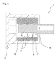
- FIG. 4 and the cross-sectional representation of Fig. 5 illustrate an alternative variant of the rolling bearing 1, is dispensed with an inner plate and instead of the inner bearing shell corresponding groove-shaped guide recess 12 are introduced on the outer circumferential surface of the shift rail 2.
- the guide recesses 12 may each have a depth which corresponds approximately to the thickness of the inner panel 4 according to the first variant.
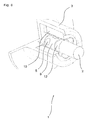
- the remaining parts correspond to the previously explained components according to the FIGS. 1 to 3 , Fig. 6 illustrates this alternative variant again in perspective.
Description
Die vorliegende Erfindung betrifft eine Wälzlagerung für axial gegeneinander verschiebbare Bauteile, insbesondere für Schaltelemente wie z.B. Schaltstangen oder Schaltschienen von Kraftfahrzeuggetrieben.The present invention relates to a roller bearing for axially mutually displaceable components, in particular for switching elements such. Shift rails or shift rails of motor vehicle transmissions.
Mittels der genannten Schaltelemente werden bei Schaltwechselgetrieben von Kraftfahrzeugen die Bewegungen von Schalt- und/oder Wählhebeln auf die jeweiligen Schieberäder des Getriebes übertragen. Schaltstangen und Schaltschienen übertragen üblicherweise axiale Betätigungskräfte auf die an diesen Elementen fixierten Schaltgabeln und übertragen die aus dem Schaltvorgang resultierenden Reaktionskräfte auf das Getriebegehäuse. Für den Schaltvorgang müssen diese Elemente axial beweglich gelagert sein.By means of said switching elements, the movements of shift and / or selector levers are transmitted to the respective sprockets of the transmission at change-speed gearboxes of motor vehicles. Shift rods and shift rails usually transmit axial actuation forces on the shift forks fixed to these elements and transmit the reaction forces resulting from the shift to the transmission housing. For the switching process, these elements must be mounted axially movable.
Aus der
Bekannte Lagerungen für Schaltstangen oder Schaltschienen können als Gleitlager oder als Wälzlager ausgebildet sein. Der Vorteil von Gleitlagerungen, die üblicherweise in Kunststoff ausgeführt sind, besteht insbesondere in ihrer Robustheit, den geringen Kosten und in der exakten Führung der Schaltelemente. Zudem weisen derartige Kunststofflagerungen den Vorteil einer akustischen Dämpfung des Schaltvorganges auf. Derartige Gleitlagerelemente sind bspw. in der
Für die Lagerung der Schaltstangen oder Schaltschienen eignen sich auch Wälzlager, bei denen üblicherweise drei oder mehr definierte, in Längsbewegungsrichtung orientierte Nuten vorgesehen sind, in denen die Wälzkörper - meist sind dies Kugeln - geführt sind. Die fluchtend in Verschieberichtuna der Bauteile angeordneten Wälzkörper laufen, wie in
Alternativ können die Kugellaufbahnen auch direkt in die Oberfläche einer Schaltstange eingebracht sein, wie dies in
Wälzlagerungen für Schaltwellen, Schaltschienen und andere verdrehbare und/oder axial gegeneinander verschiebbare Teile sind in zahlreichen Ausführungsformen bekannt. Beispiele für solche Wälzlagerungen finden sich außer in den zuvor genannten Veröffentlichungen bspw. in
Die günstigen Reibwerte der Wälzlagerungen sind nahezu lastunabhängig und liegen betragsmäßig deutlich unter den Reibwerten von bekannten Gleitlagerungen. Allerdings können durch die akustische Koppelung von Metallelementen wie Schaltschiene, Laufbleche, Kugeln, Zylinderbuchse, Getriebegehäuse etc. störende Geräusche beim Schaltvorgang von der Schiebemuffe direkt ins Getriebegehäuse und dadurch in den Fahrgastraum übertragen werden. Mehrreihige Wälzlagerungen reagieren zudem empfindlich auf Fluchtungsfehler der beiden Schaltschienenlager zueinander.The favorable coefficients of friction of the rolling bearings are virtually load-independent and, in terms of amount, are significantly below the coefficients of friction of known plain bearings. However, can be transmitted by the acoustic coupling of metal elements such as shift rail, plates, balls, cylinder liner, gear housing, etc. disturbing noise during the switching process of the sliding sleeve directly into the gear housing and thereby in the passenger compartment. Multi-row rolling bearings are also sensitive to misalignment of the two shift rail bearings to each other.
Eine Aufgabe der vorliegenden Erfindung wird darin gesehen, eine verbesserte Wälzlagerung für axial gegeneinander verschiebbare Bauteile zu liefern, die möglichst hohe Kräfte übertragen kann. Eine weitere Aufgabe der Erfindung besteht darin, eine Wälzlagerung zu liefern, die hinsichtlich der Geräuschübertragung zwischen den gegeneinander beweglichen Teilen optimiert ist.[S. 4, Zeile 31 - 33]An object of the present invention is seen to provide an improved rolling bearing for axially mutually displaceable components that can transmit the highest possible forces. Another object of the invention is to provide a roller bearing which is optimized in terms of noise transmission between the mutually movable parts. 4, lines 31 - 33]
Diese Aufgabe wird durch eine Wälzlagerung mit den Merkmalen des Anspruchs 1 gelöst.This object is achieved by a roller bearing with the features of
Zwischen Wälzkörpern und äußerem Bauteil ist eine nicht zylindrische, sondern jeweils die Konturen der Wälzkörper zumindest teilweise umschließende Außenhülse angeordnet. Die erfindungsgemäße Wälzlagerung für axial gegeneinander verschiebbare Bauteile, die insbesondere für Schaltstangen oder Schaltschienen von Kraftfahrzeuggetrieben vorgesehen sein kann, weist wenigstens zwei Reihen von jeweils fluchtend in Verschiebungsrichtung der Bauteile angeordneten Wälzkörper auf, die jeweils in Laufbahnen wälzen bzw. geführt sind, welche die Außenkontur der Wälzkörper teilweise umschlie-βen. Durch die um die Wälzkörper herum geformten Laufbahnen werden die Berührflächen zwischen Laufbahn und Wälzkörper erhöht, wodurch die Flächenpressung zwischen den Bauteilen reduziert ist; es können somit größere Kräfte sowie bei Bedarf auch Drehmomente übertragen werden.Between rolling elements and outer component is a non-cylindrical, but in each case at least partially enclosing the contours of the rolling elements Outer sleeve arranged. The roller bearing according to the invention for axially mutually displaceable components, which may be provided in particular for shift rails or shift rails of motor vehicle transmissions, has at least two rows of each aligned in the direction of displacement of the components arranged rolling elements, which roll in each case or run, which the outer contour of the Partially enclosing rolling elements. The raceways formed around the rolling elements increase the contact surfaces between the raceway and the rolling elements, thereby reducing the surface pressure between the components; It can thus be transmitted greater forces and, if necessary, torques.
Die Außenhülse mit drei Laufbahnen für zwei, drei oder mehr Reihen von Wälzkörpern weist den triovalen Querschnitt mit drei abschnittsweise kreissegmentförmigen Führungen bzw. Laufbahnen für die Wälzkörper auf, wodurch die exakte und symmetrische Führung der Kugeln gewährleistet ist. Hierdurch lässt sich die Schaltschiene besonders exakt führen. Zudem sind auch die übertragbaren Kräfte höher, da die Schaltschiene nach drei Seiten abgestützt wird. Entsprechend kann die Innenkontur drei im Querschnitt abschnittsweise kreissegmentförmige Führungen bzw. Laufbahnen für die Wälzkörper aufweisen, wodurch auch die Innenkontur bzw. das Innenblech zur Abstützung der Schaltschiene so gestaltet ist, dass möglichst geringe Flächenpressungen entstehen.The outer sleeve with three raceways for two, three or more rows of rolling elements has the triovalen cross section with three sections circular segment-shaped guides or raceways for the rolling elements, whereby the exact and symmetrical guidance of the balls is ensured. As a result, the shift rail can be carried out particularly accurately. In addition, the transferable forces are higher because the shift rail is supported on three sides. Correspondingly, the inner contour can have three cross-sectionally circular segment-shaped guides or raceways for the rolling elements, whereby the inner contour or the inner plate for supporting the shift rail is designed so that the lowest possible surface pressures arise.
Ein besonderer Vorteil der vorliegenden Erfindung ist der Ausgleich von Fluchtungsfehlern durch die elastische Außenhülse. Wenn gegenüber liegend angeordnete Lagerbohrungen im Getriebe nicht exakt fluchten und/oder Winkelfehler aufweisen, dann führt die dadurch erzwungene Verkippung in mehrreihigen Lagern bei bekannten Bauformen häufig zu Lagerschäden und frühen Ausfällen der Lager durch Beschädigungen der Laufbahnen aufgrund der unzulässigen Überlastung. Diese nachteiligen Einflüsse einer nicht ausreichend exakten Fertigung können mit der vorliegenden Erfindung auf besonders effektive Weise ausgeschlossen werden. Seite 6, Absatz 1]A particular advantage of the present invention is the compensation of misalignment by the elastic outer sleeve. If oppositely disposed bearing bores in the gearbox are not exactly aligned and / or have angular errors, then the forced tilting in multi-row bearings in known designs often leads to bearing damage and early failure of the bearings due to damage to the raceways due to unacceptable overloading. These adverse effects of insufficiently accurate manufacturing can be eliminated in a particularly effective manner with the present invention. Page 6, paragraph 1]
Da die Laufbahnen keine zylindrische Kontur aufweisen, ist eine Verdrehung der beiden gegeneinander verschiebbaren Bauteile verhindert, was die Übertragung von Drehmomenten ermöglicht.Since the raceways have no cylindrical contour, a rotation of the two mutually displaceable components is prevented, which allows the transmission of torque.
Als Wälzkörper kommen Kugeln zum Einsatz, die jeweils in Laufbahnen geführt sind, die im Querschnitt Kreisringsegmente aufweisen, die mit den Durchmessern der Wälzkörper korrespondieren. Dadurch, dass die Laufbahnen im Querschnitt jeweils den Konturen der Kugeln angepasst sind, werden die Flächenpressungen durch die größeren sich berührenden Flächen reduziert, wodurch sich auch die Bauteilbelastung verringert.As rolling elements balls are used, which are each guided in raceways, which have circular ring segments in cross section, which correspond to the diameters of the rolling elements. Because the raceways are adapted to the contours of the balls in cross-section, the surface pressures are reduced by the larger contact surfaces, which also reduces the component load.
Ein erstes Bauteil ist ein Gehäuse mit der darin angeordneten Außenhülse zur äußeren Führung der Wälzkörper. Ein zweites Bauteil kann insbesondere eine axial gegenüber dem ersten Bauteil bzw. dem Gehäuse verschiebbare Stange oder Schaltschiene sein, die eine Innenkontur zur Führung der Wälzkörper aufweist. Die erfindungsgemäße Wälzlagerung lässt sich mit Vorteil bei Schaltschienenlagerungen anwenden, so dass diese axial besser geführt ist.A first component is a housing with the outer sleeve arranged therein for the outer guidance of the rolling elements. A second component may in particular be an axially displaceable with respect to the first component or the housing rod or shift rail having an inner contour for guiding the rolling elements. The roller bearing according to the invention can be used with advantage in shift rail bearings, so that it is better axially out.
Diese weitere Aufgabe der Erfindung wird dadurch gelöst, dass die Adapterhülse aus einem elastischen Werkstoff gefestigt ist, der die Geräuschübertragung zwischen innerem Bauteil und äußerem Bauteil dämpft. Die Adapterhülse ist in einer hohlzylindrischen Bohrung des ersten Bauteils bzw. Gehäuses spielfrei fixiert. Weiterhin weist die Adapterhülse eine Innenkontur auf, die der Außenkontur der Außenhülse zur Führung der Wälzkörper entspricht. Die Außenhülse zur äußeren Lagerung und Führung der Wälzkörper ist spielfrei in der Adapterhülse fixiert. Eine besonders gute Dämpfungswirkung lässt sich erzielen, wenn die Adapterhülse aus einem elastischen Werkstoff gefertigt ist. Als solcher Werkstoff kommt bspw. ein thermoplastischer Kunststoff mit ausreichender Elastizität bzw. mit ausreichenden Dämpfungseigenschaften in Frage. Insbesondere kommt als geeigneter Werkstoff jedoch auch ein elastomerer Kunststoff mit ausreichender Festigkeit und geringer Fließneigung in Frage, so dass die notwendigen elastischen Eigenschaften in ausreichendem Maße gewährleistet sind.This further object of the invention is achieved in that the adapter sleeve is made of an elastic material which dampens the noise transmission between the inner component and the outer component. The adapter sleeve is fixed without play in a hollow cylindrical bore of the first component or housing. Furthermore, the adapter sleeve has an inner contour which corresponds to the outer contour of the outer sleeve for guiding the rolling elements. The outer sleeve for external storage and management of the rolling elements is fixed without play in the adapter sleeve. A particularly good damping effect can be achieved if the adapter sleeve is made of an elastic material. As such material is, for example, a thermoplastic material with sufficient elasticity or with sufficient damping properties in question. In particular, however, comes as a suitable material, an elastomeric plastic with sufficient strength and low flow inclination in question, so that the necessary elastic properties are ensured to a sufficient extent.
Die Innenkontur zur Führung der Wälzkörper kann weiterhin durch einen Lagerring gebildet sein, der am Außenumfang des zweiten Bauteils bzw. der Stange oder Schaltschiene fixiert ist. Alternativ hierzu kann die Innenkontur zur Führung der Wälzkörper durch Längsnuten gebildet sein, die in den Außenumfang des zweiten Bauteils bzw. der Stange oder Schaltschiene eingebracht sind. Hierzu können entsprechende Längsnuten in axialer Richtung in die Au-βenkontur der Stange oder Schaltschiene eingebracht sein, die dann als axiale Laufbahnen für die Wälzkörper bzw. Kugeln der Wälzlagerung dienen.The inner contour for guiding the rolling elements can furthermore be formed by a bearing ring, which is fixed on the outer circumference of the second component or the rod or shift rail. Alternatively, the inner contour to guide the rolling elements may be formed by longitudinal grooves in the outer periphery of the second component or the rod or shift rail are introduced. For this purpose, corresponding longitudinal grooves can be introduced in the axial direction into the outer β-contour of the rod or shift rail, which then serve as axial raceways for the rolling elements or balls of the roller bearing.
Weiterhin ist es von Vorteil, wenn die Wälzkörper durch einen Käfig gehalten und in ihrer Lage zueinander fixiert sind. Dieser Käfig ist jedoch nicht unverzichtbar, wenn er auch die Montage der Wälzkörper erheblich gegenüber einer Einzelbestückung mit Kugeln erleichtert. Der Käfig kann bspw. aus Blech bestehen. Ein geeigneter Werkstoff für den Käfig kann bspw. auch Polyamid (z.B. PA66) sein.Furthermore, it is advantageous if the rolling elements are held by a cage and fixed in position to each other. However, this cage is not indispensable, although it facilitates the installation of the rolling elements considerably compared to a single assembly with balls. The cage can, for example, consist of sheet metal. For example, a suitable material for the cage may also be polyamide (e.g., PA66).
Weitere Merkmale, Ziele und Vorteile der vorliegenden Erfindung gehen aus der nun folgenden detaillierten Beschreibung einer bevorzugten Ausführungsform der Erfindung hervor, die als nicht einschränkendes Beispiel dient und auf die beigefügten Zeichnungen Bezug nimmt. Gleiche Bauteile weisen dabei grundsätzlich gleiche Bezugszeichen auf und werden teilweise nicht mehrfach erläutert.
- Fig. 1
- zeigt einen schematischen Querschnitt einer ersten Variante einer Wälzlagerung zur axialen Führung zweier gegeneinander verschiebbarer Bauteile, insbesondere mit einer Schaltschiene mit rechteckförmigem Querschnitt.
- Fig. 2
- zeigt einen perspektivischen Teillängsschnitt der Wälzlagerung gemäß
Fig. 1 . - Fig. 3
- zeigt einen schematischen Längsschnitt der Wälzlagerung zur Verdeutlichung weiterer Details.
- Fig. 4
- zeigt einen schematischen Längsschnitt einer zweiten Variante der Wälzlagerung mit einer Schaltstange ohne inneres Führungsblech.
- Fig. 5
- zeigt einen schematischen Querschnitt der zweiten Variante aus
Fig. 4 . - Fig. 6
- zeigt eine perspektivische Darstellung der Wälzlagerung gemäß
Fig. 4 undFig. 5 .
- Fig. 1
- shows a schematic cross section of a first variant of a roller bearing for the axial guidance of two mutually displaceable components, in particular with a shift rail with a rectangular cross-section.
- Fig. 2
- shows a perspective partial longitudinal section of the rolling bearing according to
Fig. 1 , - Fig. 3
- shows a schematic longitudinal section of the roller bearing to illustrate further details.
- Fig. 4
- shows a schematic longitudinal section of a second variant of the rolling bearing with a shift rod without inner guide plate.
- Fig. 5
- shows a schematic cross section of the second variant
Fig. 4 , - Fig. 6
- shows a perspective view of the rolling bearing according to
Fig. 4 andFig. 5 ,
Die schematische Darstellung der
In gleicher Weise sind die Kugeln bzw. Wälzkörper 5 außen in einer Außenhülse 7 geführt, die eine triovale Querschnittskontur oder eine anders geartete Kontur aufweisen kann. Wichtig ist auch hier, dass die äußeren Führungsabschnitte 8 axial gleichmäßig verlaufen und im Querschnitt einen Kreissegmentabschnitt aufweisen, dessen Radius dem Radius der Wälzkörper 5 entspricht, so dass diese über einen definierten Bereich umfasst und geführt sind, wodurch die wirksame Flächenpressung zwischen Wälzkörpern 5 und Außenhülse 7 bzw. dessen Führungsabschnitten 8 gegenüber einer herkömmlichen, hohlzylindrisch geformten Axiallagerung deutlich reduziert ist.In the same way, the balls or rolling
Ein Käfig 9 dient zur exakten Führung der Wälzkörper 5 zwischen Innenblech 4 und Außenhülse 7 sowie zur Sicherstellung eines gleichmäßigen Abstandes zwischen den Wälzkörpern 5.A
Anhand der Darstellung der
Mit Hilfe dieser zusätzlichen Adapterhülse 10 wird eine Wälzlagerung 1 geliefert, die hinsichtlich der Geräuschübertragung zwischen den gegeneinander beweglichen Teilen optimiert ist. Die Adapterhülse 10 wirkt somit als Dämpfungselement und ist vorzugsweise aus einem elastischen Werkstoff gefertigt, der die Geräusch- und Vibrationsübertragung zwischen Schaltschiene 2 und Getriebegehäuse 3 dämpfen kann. Eine besonders gute Dämpfungswirkung lässt sich erzielen, wenn die Adapterhülse aus einem elastischen Werkstoff mit exakt abgestimmtem Elastizitätsverhalten gefertigt ist. Als solcher Werkstoff kommt bspw. ein thermoplastischer Kunststoff mit ausreichender Elastizität bzw. mit ausreichenden Dämpfungseigenschaften in Frage. Insbesondere kommt als geeigneter Werkstoff jedoch auch ein elastomerer Kunststoff mit ausreichender Festigkeit in Frage, so dass die notwendigen elastischen Eigenschaften in ausreichendem Maße gewährleistet sind.With the help of this
Gerade diese Elastizität führt zu einem weiteren Vorteil der Erfindung, nämlich der Möglichkeit des Ausgleichs von Fluchtungsfehlern gegenüber liegend angeordneter Schaltschienen- oder Schaltstangenlagerungen. Fluchtungsfehler rufen Verspannungen innerhalb der Lagereinheit und damit eine starke Überhöhung der Pressung der Wälzkörper auf die Laufbahnoberflächen hervor, wodurch die zulässige Lagerbelastung überschritten werden kann, was damit zur Beschädigung oder Zerstörung des Lagers führen kann.Just this elasticity leads to a further advantage of the invention, namely the possibility of compensation for misalignment over horizontally arranged shift rail or shift rod bearings. Misalignment causes stresses within the bearing unit and thus a strong exaggeration of the pressure of the rolling elements on the raceway surfaces, whereby the permissible bearing load can be exceeded, which can thus lead to damage or destruction of the bearing.
Die
Die schematische Längsschnittdarstellung der
Die schematische Längsschnittdarstellung der
Die Erfindung ist nicht auf die vorstehenden Ausführungsbeispiele beschränkt. Vielmehr ist eine Vielzahl von Varianten und Abwandlungen denkbar, die von dem erfindungsgemäßen Gedanken Gebrauch machen und deshalb ebenfalls in den Schutzbereich fallen.The invention is not limited to the above embodiments. Rather, a variety of variants and modifications are conceivable that make use of the inventive concept and therefore also fall within the scope.
- 11
- Wälzlagerungroller bearing
- 22
- Schaltschiene, SchaltstangeShift rail, shift rod
- 33
- Getriebegehäusegearbox
- 44
- Innenblechinner panel
- 55
- Wälzkörperrolling elements
- 66
- innerer Führungsabschnittinner guide section
- 77
- Außenhülseouter sleeve
- 88th
- äußerer Führungsabschnittouter guide section
- 99
- KäfigCage
- 1010
- Adapterhülseadapter sleeve
- 1111
- Ausnehmungrecess
- 1212
- Führungsausnehmungguide recess
Claims (10)
- Anti-friction bearing (1) for components which can be displaced axially with respect to one another, in particular for selector rails (2) or selector rods of motor-vehicle gearboxes, having at least two rows of rolling bodies (5) which are arranged in each case so as to be aligned in the displacement direction of the components and roll in each case in raceways (6, 8) which partially enclose the outer contour of the rolling bodies (5),- the outer sleeve (7) having, for the outer guidance of the rolling bodies (5), a cross section which is tri-oval or corresponds in terms of the number of raceways with the number of raceways in the inner plate (4), with guides (8) or raceways, in the shape of circular segments in sections, for the rolling bodies (5), and- the inner contour having three or more guides (6) or raceways, with a cross section in the shape of circular segments in sections, for the rolling bodies (5), characterized in that- the outer sleeve (7) is fixed in a first component, a housing (3), via an adapter sleeve (10) with a cylindrical outer circumferential face.
- Anti-friction bearing according to Claim 1, characterized in that the rolling bodies (5) are in each case balls which are guided in each case in raceways (6, 8) which have, in cross section, circularly annular segments which correspond with the diameters of the rolling bodies (5).
- Anti-friction bearing according to either of Claims 1 and 2, characterized in that a second component is a rod or selector rail which can be displaced axially with respect to the first component or the housing and has an inner contour for guidance of the rolling bodies.
- Anti-friction bearing according to one of Claims 1 to 3, characterized in that the components have three radially arranged rows of rolling bodies (5) which are arranged in each case so as to be aligned in the displacement direction of the components.
- Anti-friction bearing according to one of Claims 1 to 4, characterized in that the adapter sleeve (10) is fixed without play in a hollow-cylindrical hole of the first component or housing (3).
- Anti-friction bearing according to one of Claims 1 to 5, characterized in that the adapter sleeve (10) has an inner contour which corresponds to the outer contour of the outer sleeve (7) for guidance of the rolling bodies (5), and in that the outer sleeve (7) is fixed without play in the adapter sleeve (10).
- Anti-friction bearing according to one of Claims 1 to 6, characterized in that the adapter sleeve (10) is manufactured from an elastic material.
- Anti-friction bearing according to one of Claims 1 to 7, characterized in that the inner contour for guidance of the rolling bodies (5) is formed by an inner plate (4) which is fixed on the outer circumference of the second component or the rod or selector rail (2).
- Anti-friction bearing according to one of Claims 1 to 8, characterized in that the inner contour for guidance of the rolling bodies (5) is formed by longitudinal grooves (12) which are made in the outer circumference of the second component or the rod or selector rail (2).
- Anti-friction bearing according to one of Claims 1 to 9, characterized in that the rolling bodies (5) are held and fixed in their position with respect to one another by a cage (9), in particular by an annular sheet-metal cage.
Applications Claiming Priority (2)
| Application Number | Priority Date | Filing Date | Title |
|---|---|---|---|
| DE200710043476 DE102007043476A1 (en) | 2007-09-12 | 2007-09-12 | Rolling bearing for axially mutually displaceable components, in particular for gear shift elements |
| PCT/EP2008/060538 WO2009033906A1 (en) | 2007-09-12 | 2008-08-11 | Roller bearing for components which can be displaced axially in relation to one another, in particular for shift elements of gearboxes |
Publications (2)
| Publication Number | Publication Date |
|---|---|
| EP2191154A1 EP2191154A1 (en) | 2010-06-02 |
| EP2191154B1 true EP2191154B1 (en) | 2012-11-07 |
Family
ID=40032583
Family Applications (1)
| Application Number | Title | Priority Date | Filing Date |
|---|---|---|---|
| EP08787112A Not-in-force EP2191154B1 (en) | 2007-09-12 | 2008-08-11 | Roller bearing for components which can be displaced axially in relation to one another, in particular for shift elements of gearboxes |
Country Status (3)
| Country | Link |
|---|---|
| EP (1) | EP2191154B1 (en) |
| DE (1) | DE102007043476A1 (en) |
| WO (1) | WO2009033906A1 (en) |
Cited By (1)
| Publication number | Priority date | Publication date | Assignee | Title |
|---|---|---|---|---|
| CN105518353A (en) * | 2013-09-25 | 2016-04-20 | 舍弗勒技术股份两合公司 | Actuator |
Families Citing this family (1)
| Publication number | Priority date | Publication date | Assignee | Title |
|---|---|---|---|---|
| DE102019004632A1 (en) * | 2019-07-05 | 2021-01-07 | Ewellix AB | Linear bearing unit with a soundproofing device |
Family Cites Families (12)
| Publication number | Priority date | Publication date | Assignee | Title |
|---|---|---|---|---|
| US2400374A (en) | 1943-11-03 | 1946-05-14 | Ex Cell O Corp | Control means for antifriction bearings |
| US3876265A (en) * | 1973-09-24 | 1975-04-08 | Rockwell International Corp | Anti-friction ball bearing assembly |
| DE3402523A1 (en) | 1984-01-26 | 1985-08-01 | INA Wälzlager Schaeffler KG, 8522 Herzogenaurach | ROLLER BEARING FOR LONGITUDINAL MOVEMENTS FOR GUIDING A ROD WITH RECTANGULAR CROSS-SECTION |
| SE450153B (en) | 1985-01-22 | 1987-06-09 | Ffv Affersverket | TELESCOPE CONTROL, SPECIAL FOR TRANSMISSION OF TORQUE |
| FR2650867B1 (en) | 1989-08-10 | 1994-10-14 | Nadella | PRE-STRESSED RADIAL BEARING AND ITS APPLICATION IN PARTICULAR TO AUTOMOTIVE SUSPENSIONS |
| DE3940488A1 (en) | 1989-12-07 | 1991-06-13 | Schaeffler Waelzlager Kg | Guide for balls in telescopic drive shafts - has outer and inner shaft sections with opposite facing tracks and spacer springs |
| JP2789383B2 (en) | 1990-09-26 | 1998-08-20 | 安藤電気株式会社 | Clock loss detection circuit |
| DE10053987A1 (en) | 2000-10-31 | 2002-05-08 | Ina Schaeffler Kg | Length-adjustable shaft consist of inner and outer shafts, linear ball bearings, end and middle sections, and corrugated parts. |
| DE10215873B4 (en) | 2002-04-11 | 2009-07-16 | Schaeffler Kg | Snap connection between a switching element and a piston |
| DE10359962B4 (en) | 2003-12-18 | 2005-12-29 | Nacam Deutschland Gmbh | Bearing device for motor vehicle steering shafts |
| DE102004002804B4 (en) | 2004-01-19 | 2006-05-11 | Kochendörfer & Kiep Stanz- und Feinstanzwerk GmbH & Co. KG | Vehicle gearbox with shift rails that can be moved together in bearings |
| DE102006032782A1 (en) | 2005-09-14 | 2007-03-15 | Dühlmeyer Konstruktion, Werkzeug- und Formenbau GmbH | Gear shift element for transmission in motor vehicle has guide elements of plastic each consisting of at least two sections which in in-use position are fitted together around guide rail and/or connected to it |
-
2007
- 2007-09-12 DE DE200710043476 patent/DE102007043476A1/en not_active Withdrawn
-
2008
- 2008-08-11 EP EP08787112A patent/EP2191154B1/en not_active Not-in-force
- 2008-08-11 WO PCT/EP2008/060538 patent/WO2009033906A1/en active Application Filing
Cited By (2)
| Publication number | Priority date | Publication date | Assignee | Title |
|---|---|---|---|---|
| CN105518353A (en) * | 2013-09-25 | 2016-04-20 | 舍弗勒技术股份两合公司 | Actuator |
| CN105518353B (en) * | 2013-09-25 | 2017-12-01 | 舍弗勒技术股份两合公司 | Commanding apparatus |
Also Published As
| Publication number | Publication date |
|---|---|
| WO2009033906A1 (en) | 2009-03-19 |
| EP2191154A1 (en) | 2010-06-02 |
| DE102007043476A1 (en) | 2009-03-19 |
Similar Documents
| Publication | Publication Date | Title |
|---|---|---|
| EP1907716B1 (en) | Steering system with a radially mobile bearing for a shaft | |
| WO2007036344A1 (en) | Displacement unit and joint shaft comprising a displacement unit | |
| WO2016131600A1 (en) | Intermediate steering shaft for a motor vehicle, and method for operating an intermediate steering shaft for a motor vehicle | |
| EP2379903A1 (en) | Roller bearing for two components that can be at least axially moved toward one another, particularly for transmission shifting elements | |
| DE112009002345T5 (en) | Processing video data in devices with limited resources | |
| DE102018129061A1 (en) | Process for the production of steering systems assisted by an electric motor and steering system supported by an electric motor | |
| DE10301082B4 (en) | Rolling bearings for linear movements | |
| DE102005046301A1 (en) | Sliding unit and cardan shaft with a sliding unit | |
| DE102011089054A1 (en) | Switching device for gear wheel-change speed gearbox of motor car, has switching sleeve including switching finger for moving components arranged adjacent to shaft, and damping unit actively arranged between switching sleeve and shaft | |
| EP3882478B1 (en) | Drive train with a yieldable coupling between a motor shaft and an input shaft of a shift gearbox | |
| DE19817290B4 (en) | Rolling along | |
| DE102019115232A1 (en) | Electromechanically assisted steering system | |
| WO2010060625A1 (en) | Device for the vibration-reducing transmission of torques | |
| DE102009050121B4 (en) | Reduction gear with worm and worm wheel | |
| EP2191154B1 (en) | Roller bearing for components which can be displaced axially in relation to one another, in particular for shift elements of gearboxes | |
| DE102012007329A1 (en) | Shaft-hub-connection, particularly for fixing roller bearing in ball screw nut of electromechanical steering system of vehicle, has mounting ring, whose contact surfaces include angle in range of five degree to fifty degree with each other | |
| DE102007045671A1 (en) | Antifriction bearing for component, particularly for gear switching element, e.g. gear shift rail or shift rod of motor vehicle gear, has inner bearing seat closed in gear shift rail | |
| DE10359962B4 (en) | Bearing device for motor vehicle steering shafts | |
| DE102017125149B4 (en) | Planetary roller screw, actuator and release system | |
| EP2056430B1 (en) | Motor gearbox module | |
| DE102008016798B4 (en) | Rolling and steering gear with such a rolling bearing | |
| DE102019100139A1 (en) | Steering shaft for a motor vehicle | |
| WO2003033925A1 (en) | Linear roller bearing | |
| DE102010050168A1 (en) | Axially secured shaft-hub connection | |
| EP3519227A1 (en) | Final drive for a motor vehicle |
Legal Events
| Date | Code | Title | Description |
|---|---|---|---|
| PUAI | Public reference made under article 153(3) epc to a published international application that has entered the european phase |
Free format text: ORIGINAL CODE: 0009012 |
|
| 17P | Request for examination filed |
Effective date: 20100412 |
|
| AK | Designated contracting states |
Kind code of ref document: A1 Designated state(s): AT BE BG CH CY CZ DE DK EE ES FI FR GB GR HR HU IE IS IT LI LT LU LV MC MT NL NO PL PT RO SE SI SK TR |
|
| AX | Request for extension of the european patent |
Extension state: AL BA MK RS |
|
| DAX | Request for extension of the european patent (deleted) | ||
| 17Q | First examination report despatched |
Effective date: 20110407 |
|
| RAP1 | Party data changed (applicant data changed or rights of an application transferred) |
Owner name: SCHAEFFLER TECHNOLOGIES GMBH & CO. KG |
|
| RAP1 | Party data changed (applicant data changed or rights of an application transferred) |
Owner name: SCHAEFFLER TECHNOLOGIES AG & CO. KG |
|
| GRAP | Despatch of communication of intention to grant a patent |
Free format text: ORIGINAL CODE: EPIDOSNIGR1 |
|
| GRAS | Grant fee paid |
Free format text: ORIGINAL CODE: EPIDOSNIGR3 |
|
| GRAA | (expected) grant |
Free format text: ORIGINAL CODE: 0009210 |
|
| AK | Designated contracting states |
Kind code of ref document: B1 Designated state(s): AT BE BG CH CY CZ DE DK EE ES FI FR GB GR HR HU IE IS IT LI LT LU LV MC MT NL NO PL PT RO SE SI SK TR |
|
| REG | Reference to a national code |
Ref country code: GB Ref legal event code: FG4D Free format text: NOT ENGLISH |
|
| REG | Reference to a national code |
Ref country code: CH Ref legal event code: EP Ref country code: AT Ref legal event code: REF Ref document number: 583137 Country of ref document: AT Kind code of ref document: T Effective date: 20121115 |
|
| REG | Reference to a national code |
Ref country code: IE Ref legal event code: FG4D Free format text: LANGUAGE OF EP DOCUMENT: GERMAN |
|
| REG | Reference to a national code |
Ref country code: DE Ref legal event code: R096 Ref document number: 502008008608 Country of ref document: DE Effective date: 20130103 |
|
| REG | Reference to a national code |
Ref country code: NL Ref legal event code: VDEP Effective date: 20121107 |
|
| REG | Reference to a national code |
Ref country code: LT Ref legal event code: MG4D |
|
| PG25 | Lapsed in a contracting state [announced via postgrant information from national office to epo] |
Ref country code: LT Free format text: LAPSE BECAUSE OF FAILURE TO SUBMIT A TRANSLATION OF THE DESCRIPTION OR TO PAY THE FEE WITHIN THE PRESCRIBED TIME-LIMIT Effective date: 20121107 Ref country code: NO Free format text: LAPSE BECAUSE OF FAILURE TO SUBMIT A TRANSLATION OF THE DESCRIPTION OR TO PAY THE FEE WITHIN THE PRESCRIBED TIME-LIMIT Effective date: 20130207 Ref country code: NL Free format text: LAPSE BECAUSE OF FAILURE TO SUBMIT A TRANSLATION OF THE DESCRIPTION OR TO PAY THE FEE WITHIN THE PRESCRIBED TIME-LIMIT Effective date: 20121107 Ref country code: FI Free format text: LAPSE BECAUSE OF FAILURE TO SUBMIT A TRANSLATION OF THE DESCRIPTION OR TO PAY THE FEE WITHIN THE PRESCRIBED TIME-LIMIT Effective date: 20121107 Ref country code: SE Free format text: LAPSE BECAUSE OF FAILURE TO SUBMIT A TRANSLATION OF THE DESCRIPTION OR TO PAY THE FEE WITHIN THE PRESCRIBED TIME-LIMIT Effective date: 20121107 Ref country code: IS Free format text: LAPSE BECAUSE OF FAILURE TO SUBMIT A TRANSLATION OF THE DESCRIPTION OR TO PAY THE FEE WITHIN THE PRESCRIBED TIME-LIMIT Effective date: 20130307 Ref country code: HR Free format text: LAPSE BECAUSE OF FAILURE TO SUBMIT A TRANSLATION OF THE DESCRIPTION OR TO PAY THE FEE WITHIN THE PRESCRIBED TIME-LIMIT Effective date: 20121107 |
|
| PG25 | Lapsed in a contracting state [announced via postgrant information from national office to epo] |
Ref country code: SI Free format text: LAPSE BECAUSE OF FAILURE TO SUBMIT A TRANSLATION OF THE DESCRIPTION OR TO PAY THE FEE WITHIN THE PRESCRIBED TIME-LIMIT Effective date: 20121107 Ref country code: PT Free format text: LAPSE BECAUSE OF FAILURE TO SUBMIT A TRANSLATION OF THE DESCRIPTION OR TO PAY THE FEE WITHIN THE PRESCRIBED TIME-LIMIT Effective date: 20130307 Ref country code: GR Free format text: LAPSE BECAUSE OF FAILURE TO SUBMIT A TRANSLATION OF THE DESCRIPTION OR TO PAY THE FEE WITHIN THE PRESCRIBED TIME-LIMIT Effective date: 20130208 Ref country code: PL Free format text: LAPSE BECAUSE OF FAILURE TO SUBMIT A TRANSLATION OF THE DESCRIPTION OR TO PAY THE FEE WITHIN THE PRESCRIBED TIME-LIMIT Effective date: 20121107 Ref country code: LV Free format text: LAPSE BECAUSE OF FAILURE TO SUBMIT A TRANSLATION OF THE DESCRIPTION OR TO PAY THE FEE WITHIN THE PRESCRIBED TIME-LIMIT Effective date: 20121107 |
|
| PG25 | Lapsed in a contracting state [announced via postgrant information from national office to epo] |
Ref country code: CZ Free format text: LAPSE BECAUSE OF FAILURE TO SUBMIT A TRANSLATION OF THE DESCRIPTION OR TO PAY THE FEE WITHIN THE PRESCRIBED TIME-LIMIT Effective date: 20121107 Ref country code: BG Free format text: LAPSE BECAUSE OF FAILURE TO SUBMIT A TRANSLATION OF THE DESCRIPTION OR TO PAY THE FEE WITHIN THE PRESCRIBED TIME-LIMIT Effective date: 20130207 Ref country code: DK Free format text: LAPSE BECAUSE OF FAILURE TO SUBMIT A TRANSLATION OF THE DESCRIPTION OR TO PAY THE FEE WITHIN THE PRESCRIBED TIME-LIMIT Effective date: 20121107 Ref country code: SK Free format text: LAPSE BECAUSE OF FAILURE TO SUBMIT A TRANSLATION OF THE DESCRIPTION OR TO PAY THE FEE WITHIN THE PRESCRIBED TIME-LIMIT Effective date: 20121107 Ref country code: EE Free format text: LAPSE BECAUSE OF FAILURE TO SUBMIT A TRANSLATION OF THE DESCRIPTION OR TO PAY THE FEE WITHIN THE PRESCRIBED TIME-LIMIT Effective date: 20121107 |
|
| PG25 | Lapsed in a contracting state [announced via postgrant information from national office to epo] |
Ref country code: RO Free format text: LAPSE BECAUSE OF FAILURE TO SUBMIT A TRANSLATION OF THE DESCRIPTION OR TO PAY THE FEE WITHIN THE PRESCRIBED TIME-LIMIT Effective date: 20121107 Ref country code: IT Free format text: LAPSE BECAUSE OF FAILURE TO SUBMIT A TRANSLATION OF THE DESCRIPTION OR TO PAY THE FEE WITHIN THE PRESCRIBED TIME-LIMIT Effective date: 20121107 |
|
| PLBE | No opposition filed within time limit |
Free format text: ORIGINAL CODE: 0009261 |
|
| STAA | Information on the status of an ep patent application or granted ep patent |
Free format text: STATUS: NO OPPOSITION FILED WITHIN TIME LIMIT |
|
| 26N | No opposition filed |
Effective date: 20130808 |
|
| PG25 | Lapsed in a contracting state [announced via postgrant information from national office to epo] |
Ref country code: ES Free format text: LAPSE BECAUSE OF FAILURE TO SUBMIT A TRANSLATION OF THE DESCRIPTION OR TO PAY THE FEE WITHIN THE PRESCRIBED TIME-LIMIT Effective date: 20130218 |
|
| PG25 | Lapsed in a contracting state [announced via postgrant information from national office to epo] |
Ref country code: CY Free format text: LAPSE BECAUSE OF FAILURE TO SUBMIT A TRANSLATION OF THE DESCRIPTION OR TO PAY THE FEE WITHIN THE PRESCRIBED TIME-LIMIT Effective date: 20121107 |
|
| REG | Reference to a national code |
Ref country code: DE Ref legal event code: R097 Ref document number: 502008008608 Country of ref document: DE Effective date: 20130808 |
|
| BERE | Be: lapsed |
Owner name: SCHAEFFLER TECHNOLOGIES A.G. & CO. KG Effective date: 20130831 |
|
| REG | Reference to a national code |
Ref country code: DE Ref legal event code: R081 Ref document number: 502008008608 Country of ref document: DE Owner name: SCHAEFFLER TECHNOLOGIES AG & CO. KG, DE Free format text: FORMER OWNER: SCHAEFFLER TECHNOLOGIES AG & CO. KG, 91074 HERZOGENAURACH, DE Effective date: 20140214 Ref country code: DE Ref legal event code: R081 Ref document number: 502008008608 Country of ref document: DE Owner name: SCHAEFFLER TECHNOLOGIES GMBH & CO. KG, DE Free format text: FORMER OWNER: SCHAEFFLER TECHNOLOGIES AG & CO. KG, 91074 HERZOGENAURACH, DE Effective date: 20140214 |
|
| REG | Reference to a national code |
Ref country code: CH Ref legal event code: PL |
|
| GBPC | Gb: european patent ceased through non-payment of renewal fee |
Effective date: 20130811 |
|
| PG25 | Lapsed in a contracting state [announced via postgrant information from national office to epo] |
Ref country code: CH Free format text: LAPSE BECAUSE OF NON-PAYMENT OF DUE FEES Effective date: 20130831 Ref country code: LI Free format text: LAPSE BECAUSE OF NON-PAYMENT OF DUE FEES Effective date: 20130831 Ref country code: MC Free format text: LAPSE BECAUSE OF FAILURE TO SUBMIT A TRANSLATION OF THE DESCRIPTION OR TO PAY THE FEE WITHIN THE PRESCRIBED TIME-LIMIT Effective date: 20121107 |
|
| REG | Reference to a national code |
Ref country code: IE Ref legal event code: MM4A |
|
| REG | Reference to a national code |
Ref country code: FR Ref legal event code: ST Effective date: 20140430 |
|
| PG25 | Lapsed in a contracting state [announced via postgrant information from national office to epo] |
Ref country code: BE Free format text: LAPSE BECAUSE OF NON-PAYMENT OF DUE FEES Effective date: 20130831 |
|
| PG25 | Lapsed in a contracting state [announced via postgrant information from national office to epo] |
Ref country code: GB Free format text: LAPSE BECAUSE OF NON-PAYMENT OF DUE FEES Effective date: 20130811 Ref country code: IE Free format text: LAPSE BECAUSE OF NON-PAYMENT OF DUE FEES Effective date: 20130811 |
|
| PG25 | Lapsed in a contracting state [announced via postgrant information from national office to epo] |
Ref country code: FR Free format text: LAPSE BECAUSE OF NON-PAYMENT OF DUE FEES Effective date: 20130902 |
|
| REG | Reference to a national code |
Ref country code: AT Ref legal event code: MM01 Ref document number: 583137 Country of ref document: AT Kind code of ref document: T Effective date: 20130811 |
|
| PG25 | Lapsed in a contracting state [announced via postgrant information from national office to epo] |
Ref country code: AT Free format text: LAPSE BECAUSE OF NON-PAYMENT OF DUE FEES Effective date: 20130811 |
|
| REG | Reference to a national code |
Ref country code: DE Ref legal event code: R081 Ref document number: 502008008608 Country of ref document: DE Owner name: SCHAEFFLER TECHNOLOGIES AG & CO. KG, DE Free format text: FORMER OWNER: SCHAEFFLER TECHNOLOGIES GMBH & CO. KG, 91074 HERZOGENAURACH, DE Effective date: 20150402 |
|
| PG25 | Lapsed in a contracting state [announced via postgrant information from national office to epo] |
Ref country code: TR Free format text: LAPSE BECAUSE OF FAILURE TO SUBMIT A TRANSLATION OF THE DESCRIPTION OR TO PAY THE FEE WITHIN THE PRESCRIBED TIME-LIMIT Effective date: 20121107 Ref country code: MT Free format text: LAPSE BECAUSE OF FAILURE TO SUBMIT A TRANSLATION OF THE DESCRIPTION OR TO PAY THE FEE WITHIN THE PRESCRIBED TIME-LIMIT Effective date: 20121107 |
|
| PG25 | Lapsed in a contracting state [announced via postgrant information from national office to epo] |
Ref country code: LU Free format text: LAPSE BECAUSE OF NON-PAYMENT OF DUE FEES Effective date: 20130811 Ref country code: HU Free format text: LAPSE BECAUSE OF FAILURE TO SUBMIT A TRANSLATION OF THE DESCRIPTION OR TO PAY THE FEE WITHIN THE PRESCRIBED TIME-LIMIT; INVALID AB INITIO Effective date: 20080811 |
|
| PGFP | Annual fee paid to national office [announced via postgrant information from national office to epo] |
Ref country code: DE Payment date: 20191031 Year of fee payment: 12 |
|
| REG | Reference to a national code |
Ref country code: DE Ref legal event code: R119 Ref document number: 502008008608 Country of ref document: DE |
|
| PG25 | Lapsed in a contracting state [announced via postgrant information from national office to epo] |
Ref country code: DE Free format text: LAPSE BECAUSE OF NON-PAYMENT OF DUE FEES Effective date: 20210302 |
|
| P01 | Opt-out of the competence of the unified patent court (upc) registered |
Effective date: 20230522 |