EP2190765B1 - Device and method for controlling a web - Google Patents
Device and method for controlling a web Download PDFInfo
- Publication number
- EP2190765B1 EP2190765B1 EP08794106.8A EP08794106A EP2190765B1 EP 2190765 B1 EP2190765 B1 EP 2190765B1 EP 08794106 A EP08794106 A EP 08794106A EP 2190765 B1 EP2190765 B1 EP 2190765B1
- Authority
- EP
- European Patent Office
- Prior art keywords
- web
- control device
- centre line
- pattern
- line
- Prior art date
- Legal status (The legal status is an assumption and is not a legal conclusion. Google has not performed a legal analysis and makes no representation as to the accuracy of the status listed.)
- Not-in-force
Links
Images


Classifications
-
- B—PERFORMING OPERATIONS; TRANSPORTING
- B65—CONVEYING; PACKING; STORING; HANDLING THIN OR FILAMENTARY MATERIAL
- B65H—HANDLING THIN OR FILAMENTARY MATERIAL, e.g. SHEETS, WEBS, CABLES
- B65H39/00—Associating, collating, or gathering articles or webs
- B65H39/16—Associating two or more webs
-
- A—HUMAN NECESSITIES
- A61—MEDICAL OR VETERINARY SCIENCE; HYGIENE
- A61F—FILTERS IMPLANTABLE INTO BLOOD VESSELS; PROSTHESES; DEVICES PROVIDING PATENCY TO, OR PREVENTING COLLAPSING OF, TUBULAR STRUCTURES OF THE BODY, e.g. STENTS; ORTHOPAEDIC, NURSING OR CONTRACEPTIVE DEVICES; FOMENTATION; TREATMENT OR PROTECTION OF EYES OR EARS; BANDAGES, DRESSINGS OR ABSORBENT PADS; FIRST-AID KITS
- A61F13/00—Bandages or dressings; Absorbent pads
- A61F13/15—Absorbent pads, e.g. sanitary towels, swabs or tampons for external or internal application to the body; Supporting or fastening means therefor; Tampon applicators
- A61F13/15577—Apparatus or processes for manufacturing
- A61F13/15772—Control
-
- B—PERFORMING OPERATIONS; TRANSPORTING
- B32—LAYERED PRODUCTS
- B32B—LAYERED PRODUCTS, i.e. PRODUCTS BUILT-UP OF STRATA OF FLAT OR NON-FLAT, e.g. CELLULAR OR HONEYCOMB, FORM
- B32B37/00—Methods or apparatus for laminating, e.g. by curing or by ultrasonic bonding
- B32B37/0046—Methods or apparatus for laminating, e.g. by curing or by ultrasonic bonding characterised by constructional aspects of the apparatus
-
- B—PERFORMING OPERATIONS; TRANSPORTING
- B32—LAYERED PRODUCTS
- B32B—LAYERED PRODUCTS, i.e. PRODUCTS BUILT-UP OF STRATA OF FLAT OR NON-FLAT, e.g. CELLULAR OR HONEYCOMB, FORM
- B32B38/00—Ancillary operations in connection with laminating processes
- B32B38/18—Handling of layers or the laminate
- B32B38/1825—Handling of layers or the laminate characterised by the control or constructional features of devices for tensioning, stretching or registration
- B32B38/1833—Positioning, e.g. registration or centering
- B32B38/1841—Positioning, e.g. registration or centering during laying up
-
- B—PERFORMING OPERATIONS; TRANSPORTING
- B65—CONVEYING; PACKING; STORING; HANDLING THIN OR FILAMENTARY MATERIAL
- B65H—HANDLING THIN OR FILAMENTARY MATERIAL, e.g. SHEETS, WEBS, CABLES
- B65H19/00—Changing the web roll
- B65H19/10—Changing the web roll in unwinding mechanisms or in connection with unwinding operations
- B65H19/18—Attaching, e.g. pasting, the replacement web to the expiring web
- B65H19/1842—Attaching, e.g. pasting, the replacement web to the expiring web standing splicing, i.e. the expiring web being stationary during splicing contact
- B65H19/1852—Attaching, e.g. pasting, the replacement web to the expiring web standing splicing, i.e. the expiring web being stationary during splicing contact taking place at a distance from the replacement roll
-
- B—PERFORMING OPERATIONS; TRANSPORTING
- B65—CONVEYING; PACKING; STORING; HANDLING THIN OR FILAMENTARY MATERIAL
- B65H—HANDLING THIN OR FILAMENTARY MATERIAL, e.g. SHEETS, WEBS, CABLES
- B65H23/00—Registering, tensioning, smoothing or guiding webs
- B65H23/02—Registering, tensioning, smoothing or guiding webs transversely
- B65H23/032—Controlling transverse register of web
-
- B—PERFORMING OPERATIONS; TRANSPORTING
- B65—CONVEYING; PACKING; STORING; HANDLING THIN OR FILAMENTARY MATERIAL
- B65H—HANDLING THIN OR FILAMENTARY MATERIAL, e.g. SHEETS, WEBS, CABLES
- B65H39/00—Associating, collating, or gathering articles or webs
- B65H39/14—Associating sheets with webs
-
- G—PHYSICS
- G06—COMPUTING; CALCULATING OR COUNTING
- G06T—IMAGE DATA PROCESSING OR GENERATION, IN GENERAL
- G06T7/00—Image analysis
- G06T7/0002—Inspection of images, e.g. flaw detection
- G06T7/0004—Industrial image inspection
-
- G—PHYSICS
- G06—COMPUTING; CALCULATING OR COUNTING
- G06V—IMAGE OR VIDEO RECOGNITION OR UNDERSTANDING
- G06V10/00—Arrangements for image or video recognition or understanding
- G06V10/20—Image preprocessing
- G06V10/24—Aligning, centring, orientation detection or correction of the image
- G06V10/245—Aligning, centring, orientation detection or correction of the image by locating a pattern; Special marks for positioning
-
- B—PERFORMING OPERATIONS; TRANSPORTING
- B32—LAYERED PRODUCTS
- B32B—LAYERED PRODUCTS, i.e. PRODUCTS BUILT-UP OF STRATA OF FLAT OR NON-FLAT, e.g. CELLULAR OR HONEYCOMB, FORM
- B32B2309/00—Parameters for the laminating or treatment process; Apparatus details
- B32B2309/70—Automated, e.g. using a computer or microcomputer
- B32B2309/72—For measuring or regulating, e.g. systems with feedback loops
-
- B—PERFORMING OPERATIONS; TRANSPORTING
- B32—LAYERED PRODUCTS
- B32B—LAYERED PRODUCTS, i.e. PRODUCTS BUILT-UP OF STRATA OF FLAT OR NON-FLAT, e.g. CELLULAR OR HONEYCOMB, FORM
- B32B2555/00—Personal care
- B32B2555/02—Diapers or napkins
-
- B—PERFORMING OPERATIONS; TRANSPORTING
- B32—LAYERED PRODUCTS
- B32B—LAYERED PRODUCTS, i.e. PRODUCTS BUILT-UP OF STRATA OF FLAT OR NON-FLAT, e.g. CELLULAR OR HONEYCOMB, FORM
- B32B37/00—Methods or apparatus for laminating, e.g. by curing or by ultrasonic bonding
- B32B37/14—Methods or apparatus for laminating, e.g. by curing or by ultrasonic bonding characterised by the properties of the layers
- B32B37/16—Methods or apparatus for laminating, e.g. by curing or by ultrasonic bonding characterised by the properties of the layers with all layers existing as coherent layers before laminating
- B32B37/22—Methods or apparatus for laminating, e.g. by curing or by ultrasonic bonding characterised by the properties of the layers with all layers existing as coherent layers before laminating involving the assembly of both discrete and continuous layers
- B32B37/223—One or more of the layers being plastic
-
- B—PERFORMING OPERATIONS; TRANSPORTING
- B65—CONVEYING; PACKING; STORING; HANDLING THIN OR FILAMENTARY MATERIAL
- B65H—HANDLING THIN OR FILAMENTARY MATERIAL, e.g. SHEETS, WEBS, CABLES
- B65H2511/00—Dimensions; Position; Numbers; Identification; Occurrences
- B65H2511/40—Identification
- B65H2511/413—Identification of image
-
- B—PERFORMING OPERATIONS; TRANSPORTING
- B65—CONVEYING; PACKING; STORING; HANDLING THIN OR FILAMENTARY MATERIAL
- B65H—HANDLING THIN OR FILAMENTARY MATERIAL, e.g. SHEETS, WEBS, CABLES
- B65H2511/00—Dimensions; Position; Numbers; Identification; Occurrences
- B65H2511/50—Occurence
- B65H2511/51—Presence
- B65H2511/512—Marks, e.g. invisible to the human eye; Patterns
-
- B—PERFORMING OPERATIONS; TRANSPORTING
- B65—CONVEYING; PACKING; STORING; HANDLING THIN OR FILAMENTARY MATERIAL
- B65H—HANDLING THIN OR FILAMENTARY MATERIAL, e.g. SHEETS, WEBS, CABLES
- B65H2553/00—Sensing or detecting means
- B65H2553/40—Sensing or detecting means using optical, e.g. photographic, elements
- B65H2553/42—Cameras
-
- B—PERFORMING OPERATIONS; TRANSPORTING
- B65—CONVEYING; PACKING; STORING; HANDLING THIN OR FILAMENTARY MATERIAL
- B65H—HANDLING THIN OR FILAMENTARY MATERIAL, e.g. SHEETS, WEBS, CABLES
- B65H2557/00—Means for control not provided for in groups B65H2551/00 - B65H2555/00
- B65H2557/20—Calculating means; Controlling methods
- B65H2557/24—Calculating methods; Mathematic models
-
- B—PERFORMING OPERATIONS; TRANSPORTING
- B65—CONVEYING; PACKING; STORING; HANDLING THIN OR FILAMENTARY MATERIAL
- B65H—HANDLING THIN OR FILAMENTARY MATERIAL, e.g. SHEETS, WEBS, CABLES
- B65H2801/00—Application field
- B65H2801/57—Diaper manufacture
-
- Y—GENERAL TAGGING OF NEW TECHNOLOGICAL DEVELOPMENTS; GENERAL TAGGING OF CROSS-SECTIONAL TECHNOLOGIES SPANNING OVER SEVERAL SECTIONS OF THE IPC; TECHNICAL SUBJECTS COVERED BY FORMER USPC CROSS-REFERENCE ART COLLECTIONS [XRACs] AND DIGESTS
- Y10—TECHNICAL SUBJECTS COVERED BY FORMER USPC
- Y10T—TECHNICAL SUBJECTS COVERED BY FORMER US CLASSIFICATION
- Y10T29/00—Metal working
- Y10T29/49—Method of mechanical manufacture
- Y10T29/49826—Assembling or joining
-
- Y—GENERAL TAGGING OF NEW TECHNOLOGICAL DEVELOPMENTS; GENERAL TAGGING OF CROSS-SECTIONAL TECHNOLOGIES SPANNING OVER SEVERAL SECTIONS OF THE IPC; TECHNICAL SUBJECTS COVERED BY FORMER USPC CROSS-REFERENCE ART COLLECTIONS [XRACs] AND DIGESTS
- Y10—TECHNICAL SUBJECTS COVERED BY FORMER USPC
- Y10T—TECHNICAL SUBJECTS COVERED BY FORMER US CLASSIFICATION
- Y10T29/00—Metal working
- Y10T29/53—Means to assemble or disassemble
Definitions
- the invention relates to an adaptive assembly line for assembly of a continuous first web to a continuous or discontinuous second web.
- the assembly line is arranged to feed the first and the second web in a machine direction.
- the assembly line comprises a control device comprising a camera that takes a first picture of the first web.
- the control device comprises a first transformer for transforming the first picture into a first signal.
- the control device is arranged to control the position of a first web with relation to a second web.
- the invention also relates to a method for an adaptive assembly line.
- the sanitary napkin may comprise a topsheet, a backsheet and an absorbent body positioned therebetween.
- the absorbent body is positioned onto the conveyer belt and the topsheet is positioned onto the absorbent body.
- the topsheet or the backsheet is in the form of a continuous web that is cut after being positioned onto the absorbent body.
- the pattern has a first centre line that shall be positioned in line with a second centre line comprised in the absorbent body. It is important that the first centre line is an optic centre line, i.e. the first centre line shall be a centre line according to the eye of an observer.
- the first web comprises an elastic material the shape and form of the first web may vary due to material variations and/or strains in the material caused, for example, by machine parts in the manufacturing plant. The machine parts may be rollers and stretchers, etc. arranged to bring the first web in a machine direction.
- the first centre line changes position, and as a consequence the position of the first centre line in relation to the second centre line is changed.
- the first web As a topsheet and that the topsheet comprises two side portions of a first material and a centre portion of a second material therebetween.
- the centre portion is attached to the side portions by, for example, welding, gluing, mechanical bonding etc. and the attachment process forms seams that become part of or form the pattern of the first web.
- the seams run in the machine direction, i.e. in the feeding direction of the first and second webs.
- the position of the seams may vary somewhat with respect to the lateral side edges of the first web due to different factors such as material variations and external forces acting on the first web.
- the shifting of the position of the seams affects the position of the first centre line, i.e. the optic centre line.
- Each lateral side edge of the first web also has an extension in the machine direction and since the seams vary with respect to the lateral side edges, it is not a sufficiently good solution to calculate the first centre line from the position of one or both of the side edges since this obvious gives a wrong position of the first centre line in the first web.
- US 2004/0028268 teaches a lamination process where a first web is laminated to a second web forming a composite web.
- the process comprises the use of a camera that periodically takes pictures of the composite web.
- the pictures are converted into electrical signals and are compared to a number of selected parameters in order to determine if the first web is properly aligned with the second web.
- a problem with the process according to US 2004/0028268 is that the system detects a fault only after the composite web has been formed. The system allows for adjustment so that the fault is corrected, but the faulty part has to be rejected or accepted.
- the second centre line may be the centre line of a continuous web but may be the centre line of a broken web comprising a number of pieces of material arranged onto a conveyer belt.
- Document JP 2007-169009 discloses a manufacturing device which combines two webs. This device comprises a CCD camera placed downstream of the combination point, the CCD camera is used to control positioning of the web. Therefore, there is a need for an adaptive assembly line for detecting the first centre line and controlling the alignment of the first centre line of the first web to the second centre line of the second web, before the first web is positioned onto the second web.
- the invention intends to remedy the above deficiencies and to find an adaptive assembly line for assembly of a continuous first web to a continuous or discontinuous second web according to claim 1.
- One advantage of the invention is that a potential misalignment of the first centre line to the second centre line can be avoided before the assembly of the first web to the second web.
- the camera is used to detect a faulty laminate, i.e. after assembly, which has to be rejected upon detection.
- the control device is arranged to detect a pattern in the first web before assembly by use of the camera and a transformer that transforms a picture from the camera into electronic signals.
- the first camera is arranged to take pictures continuously or periodically.
- the control device is arranged to calculate the position of the first centre line in the first web with regard to the pattern comprised in the first web. This is done after the detection of the pattern.
- the position of the first centre line can be calculated from the knowledge of the position of the pattern in the first picture since the camera advantageously is arranged in a fixed position relative the first web.
- the fixed position of the camera gives the possibility to define, for example, a grid pattern that can be used for defining the position of the first centre line and the second centre line.
- a reference line can be arranged in the grid pattern, which reference line can be used for positioning the second web so that the second centre line is aligned with the reference pattern.
- the second centre line thus becomes known to the control device via the reference line before assembly so that the control device can calculate the misalignment between the first centre line and the second centre line before assembly.
- the first and the second centre lines extend essentially in the machine direction and the assembly line comprises a first guidance device arranged to shift the position of the first web in a cross-machine direction, i.e. in a lateral direction, for alignment of the first centre line with the second centre line before the assembly point.
- the first centre line is an optical centre line.
- the optical centre line can be defined as being a symmetrical line in a pattern where the symmetry lies in the eyes of a beholder.
- the first centre line shall be considered as a centre line in a pattern when a person is watching the pattern.
- the control device therefore comprises means for calculating the first centre line when the position of the pattern in the first web is known.
- the means for calculating may be an algorithm that can be programmed for the purpose.
- the invention is especially advantageous when the first web comprises, in a cross-machine direction, two side portions and a centre portion bonded together by two seams running in the machine direction.
- the pattern in the first web is here defined by the one of or both the two seams.
- the side portions are often made from a different material than the centre portion and for a number of reasons the seams may vary somewhat in position in the first web after bonding of the side portions and the central portion. The reasons may be a difference in the different material in different positions along the first web and may be a result of the process where machines transport the first web in the machine direction and therefore affects the first web with external forces.
- the present invention is adaptive to such variations and the control device continuously monitors any variations of lateral variations of the first centre line and controls the first guidance device accordingly.
- the assembly line may comprise a conveyer belt for bringing the second web to the assembly point.
- the second web is positioned on the conveyer belt at a predetermined position.
- the use of a predetermined position assures that the control device has information regarding the position of the second centre line.
- the conveyer belt may for example comprise a reference line that is used when the second web is positioned on the conveyer belt.
- the second centre line is then aligned with the reference line. This embodiment is especially advantageous when the second web is a discontinuous web forming absorbent bodies that are to be laminated with the first web.
- the first web may then be a topsheet or a backsheet.
- control device may be arranged to use the second signal for determining the position of the second centre line in the second web and the control device arranged to use the second signal for controlling the position of the first web and/or the second web so that the first centre line becomes aligned with the second centre line during assembly of the first web to the second web.
- This embodiment can be suitable when both the first web and the second web are continuous webs.
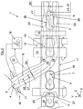
- FIG 1 schematically shows a top view of an adaptive assembly line 1 according to the invention.
- the adaptive assembly line 1 is arranged to assemble an absorbent article 2 comprising at least an absorbent body 3 and a topsheet 4 and/or a backsheet 5.
- the assembly line 1 is thus arranged to fit a continuous first web 6 to a continuous or discontinuous second web 7.
- the continuous first web 6 is the topsheet and the second web 7 is a discontinuous web in the form of a number of absorbent bodies.
- the first web 6 comprises a pattern 8 with an optical first centre line 9 and the second web 7 comprises a second centre line 10.
- the first centre line 9 and the second centre line 10 extend in the machine direction.
- machine direction refers to the feeding direction of a conveyer belt 11 comprised in the assembly line 1.
- the purpose of the assembly line 1 is to bring the first centre line 9 into alignment with the second centre line 10.
- the wording "lateral direction" will be used when describing a cross-machine direction.
- the machine direction is denoted with X and the lateral direction with Y.
- the first web 6 has been shown as being positioned on the side, Y-direction, of the second web 7 in order to more clearly describe the invention.
- the first web is shown in the figure in such a manner that it looks crooked, but this is only to be regarded as an optical illusion since the first web 6 advantageously is positioned above the second web as shown in figures 2 and 3 .
- the assembly line 1 comprises an assembly station 12 comprising an assembly point 13, also known as marriage point, where the first web 6 is attached to the second web 7 when the first centre line 9 is aligned with the second centre line 10.
- the assembly point 13 comprises a bonding device 14 for bonding the first web 6 to the second web 7.
- the assembly line also comprises a separating device 15 for separating the first web 6 into pieces.
- the assembly line 1 comprises a conveyer belt 11 onto which the first web 6 and the second web are positioned for assembly. If the second web 7 would have been a continuous web the conveyer belt 11 could have been opted out and a different type of assembly point 13 could have been chosen.
- the assembly point 13 could be a roller or any moving surface that allows transportation of the first 6 and the second web 7 while the first web 6 is attached to the second web 7 with the bonding device.
- the assembly line 1 comprises a first transport system 16 for feeding the first web 6 to the conveyer belt 11 and a second transport system for feeding the second web 7 to the conveyer belt 11.
- a second transport system 19 is arranged for positioning of the second web 7 at a pre-selected position on the conveyer belt 11.
- the second transport system 19 may be connected to the control device 18 or may be connected to a separate control device (not shown).
- the control device 18 of the first web 6 needs to comprise information on the position of the second centre line 10 in order to align the first centre line 9 with the second centre line 10.
- the pre-selected position may refer to a reference line 20 in the conveyor belt running in the machine direction of the assembly line 1.
- the second guidance device 21 is arranged to control the lateral Y position of the second web. Information regarding the position of the second centre line 10 may be fed continuously to the control device 18 for control of the relative position of the first web 6 to the second web 7 by use of the first 17 and second guidance devices 21 respectively.
- the control device 18 comprises a first camera 22 that periodically or continuously takes a number of first pictures of the first web 6.
- the control device 18 also comprises a first transformer for transforming the first pictures into a corresponding number of first signals.
- the control device 18 is arranged to control the position of the first centre line 9 in the first web 6 with relation to the second centre line 10 of the second web 7. It is an object of the invention to continuously bring the first centre line 9 in alignment with the second centre line 10.
- the first camera 22 is therefore arranged to take the first pictures before assembly of the first web 6 to the second web 7. The closer the first camera 22 is positioned to the first guidance device 17 the quicker the response when a change in the first centre line 9 is detected.
- “response” refers to the control of the lateral position of the first web 6 by use of the first guidance device.
- the control device 18 is arranged to use the first signal for determining the lateral position of the first centre line 9 in the first web 6.
- the first centre line 9 may vary somewhat due to a number of different factors. For example, one factor is different thickness of the first web 6 which gives different elastic properties which gives a movement in the first web 6 that changes the position of the first centre line 9; another factor is that the first transport system has flaws, i.e. is not perfect, and therefore applies different forces on different parts of the first web 6 which causes movement within the first web 6 which changes the position of the first centre line 9.
- the position of the first centre line 9 is determined by the aid of a picture recognizing system that transforms the first picture into a first signal, preferably an electrical signal.
- the first signal comprises information regarding any pattern 8 comprised in the first picture.
- a certain pattern 8 in the first web 6 may be developed in the picture as being darker or brighter than its surroundings, i.e. there exists a number of different contrasts in a black and white photo.
- the difference in contrast (or colour if the picture is a colour picture) in the picture gives a signature in the first signal that differs from a signature caused by a non-patterned surface.
- the picture recognizing system scans the picture in a selected way and logs position and corresponding signatures and can therefore be used for identifying the pattern 8 and for calculating the first centre line 9 of the first web 6.
- the first centre line 9 may be calculated from a mean value in the first signal or a position between certain values, but may be calculated by use of any suitable method.
- the first centre line 9 is an optical centre line.
- optical centre line means that the eye of a human observer recognizes the first centre line to be the centre line of the pattern 8 in the first web.
- the first centre line 9 need not be a mathematically correct average or mean value of the pattern 8 but may be the centre line from an artistic point of view.
- the first centre line 9 may therefore be a symmetric centre line with regard to the pattern 8.
- the control device 18 may comprise one or many stored prepared signatures, i.e. id-signals, that identify the pattern in the first picture i.e. in the first web 6. The most recent first picture is then compared to the stored pictures, i.e. id-signals, in order to find a match and to thereby give the control device information on if a pattern 8 has been found or not. If a pattern 8 has been found the position of the first centre line 9 in the first web 6 is calculated in the control device 18 by use of the detected position of the pattern.
- id-signals stored prepared signatures
- lateral side edges refer to the side edges 23 of the first web 6 that have an extension in the machine direction X.
- the problem with a travelling first centre line 9, i.e. movement in the cross-machine direction, is especially common when the first web 6 comprises, in the cross-machine direction Y, two side portions 24 and a centre portion 25 bonded together by two seams 26 in the machine direction X.
- the pattern 8 comprises the two seams 26 and the first centre line 9 shall be calculated with regard to the seams 26.
- the centre portion 25 is often made from a different material than the side portions 24 which can give different stretch of the different materials in different portions of the first web 6 which gives that the position of the seams 26 varies within the first web 6.
- the lateral position of the first centre line 9 may vary since the side portions 24 and the centre portion 25 may have different properties and may thus affect the position of the seams differently.
- the first camera 22 and control device 18 may be arranged for detection of one or both the seams 26 for calculating the first centre line 9.
- the first centre line 9 may be positioned at half the distance from one of the seams 26, i.e. in the middle of the seams 26. The best result is thus achieved when both seams 26 are detected since a more exact position of the first centre line 9 can be calculated.
- detection of one seam 26 together with an estimate of the lateral position of the first centre line is an improvement over the previously known control device where the position of the lateral side edge 23 are detected and used for control.
- Detection of one seam 26 together with an estimate of the lateral position of the first centre line 9 can advantageously be used, for example, when the other seam has been executed but the pattern of the second seam for some reason has been less visible. This can happen, for example, when an ultrasonic welding device is used for welding and where the seams comprise a number of embossed indentations that constitute the bonding areas of the seam 26.
- the embossed pattern may be less visible on one seam 26 than the other, but both the seams 26 may be adequately formed as such. The process should therefore be allowed, at least for a short while, because the pattern 8 may be weak only for a short period of time.
- the control device 18 is arranged to store previous pictures of the pattern 8 in the first web.
- the pictures are converted into identity signals (hereinafter called id-signals or signatures) that are used for identification of the pattern 8 in the first picture.
- the stored id-signals can be both identifications of correct patterns and identification of a defect or wrong pattern.
- the stored correct id-signal may be in the form of an allowable range representing different variants of the correct pattern.
- the range can be in the form of a number of id-signals representing a number of pictures and patterns, but can also be a numerical range. The advantage of using a range is that the control device can recognize a correct pattern even if the pattern differs somewhat over time, but within the allowable range.
- defect refers to a selected pattern that is not allowed.
- the control device 18 uses the stored defect pictures to recognise an already known and processed defect picture.
- the control device may use this information for activating an action plan, for example, alert an operator and/or stop the assembly line or any other suitable action plan that can be used to rectify the detected defect.
- the pattern 8 that is to be identified can be a part of a larger pattern, for example a smaller part of one or both seams; or may be the entire pattern over a selected area of the first web.
- the entire pattern may thus be one of or both the seams over a selected area in the machine direction.
- the control device 18 is advantageously arranged to calculate the lateral position of the pattern 8 in the first web 6 when the pattern 8 has been detected.
- the lateral position can be calculated from information extracted from the first picture.
- the first picture is converted into an electrical first signal and this can be done by, for example, breaking down the picture into a number of discrete elements that are investigated.
- investigated means that the control device converts the discrete element into electrical signals that represent the discrete element.
- the control device 18 also chooses an order in which the discrete elements are investigated. The described investigation is commonly referred to as scanning, but other methods for investigating the picture can be used.
- the first picture is then investigated in the same manner and is compared to the stored id-signals.
- the position of the pattern can be calculated by comparing the position of the detected pattern 8 in the picture.
- the control device 18 uses the information regarding the lateral position of the pattern to calculate the first centre line and to control the position of the first 6 and/or second web 7 so that the first centre line is brought into alignment with the second centre line 10.
- the control device 18 may advantageously comprise a logic unit that performs various mathematical tasks that are used for pattern detection purposes and control purposes according to an algorithm.
- the logic unit may, for example, be arranged to keep track of the lateral position of the pattern, i.e. one of or both the seams. If the lateral position of the pattern 8 suddenly alters above a selected threshold, the logic unit may be arranged to ignore the information as being a faulty detection of the pattern and may be arranged to either investigate the first picture again or investigate the next picture.
- the assembly line 1 comprises a second camera (not shown) that can be arranged to take second pictures of the second web.
- the assembly line 1 then comprises a second transformer for transforming the second pictures into a second signal.
- the control device 18 is arranged to use the second signal for determining the position of the second centre line 10 in the second web and the control device 18 is arranged to use the second signal for controlling a second guidance device that controls the lateral position of the second web so that the first centre line 9 becomes aligned with the second centre line 10 during assembly of the first web 6 to the second web 7.
- the assembly line 1 comprises a third camera (29; figures 2 and 3 ) that can be arranged to take third pictures of a third web 27.
- the assembly line 1 then comprises a third transformer for transforming the third pictures into a third signal.
- the control device 18 is arranged to use the third signal for determining the position of a third centre line (not shown) in the third web 27 and the control device 18 is arranged to use the third signal for controlling a third guidance device 28 that controls the lateral position of the third web 27 so that the first centre line becomes aligned with the second centre line and the third centre line during assembly of the first web to the second web.
- the first web 6 is a continuous topsheet and the second web in the form of discrete absorbent bodies and the third web a continuous backsheet.
- the conveyer belt 11 is fixed in its position and comprises a reference line 20 known to the control device 18.
- the positioning of the second 7 and third web 27 onto the conveyer belt 11 is made to this reference line 20 by use of the second 21 and third guidance devices respectively.
- the first web 6 is then positioned onto the absorbent bodies 3 so that the first centre line is aligned with the second centre line 10. Hence, the first centre line becomes aligned with the reference line.
- control device 18 may control the first web 6 only and that one or several further control devices may be comprised in the assembly line 1 for controlling the second web 7 and/or the third web 27.
- the further control device(s) may thus operate independently from the control device 18 controlling the first web and may operate independently of each other when a reference line is used.
- the control devices may also be arranged for intercommunication for control of the assembly line.
- the first camera 22 described in connection to figure 1 periodically takes pictures of the first web with a sampling frequency that is dependent on the feeding speed of the first web and the processing speed of the control device 18. The faster the feeding speed the higher the frequency.
- the first camera 22 may take pictures continuously, i.e. may film the first web with an open shutter and the control device may then draw sample pictures from the film or may calculate continuously should the processor in the first transformer and in the control device be arranged to handle such continuous processes.
- open shutter refers to the use of a camera comprising mechanical parts, but when using digital cameras or another technique the shutter is replaced by a different device that allows for light to enter a recording medium, for example a chemical film or a digital or magnetic recording device.
- the second and/or the third camera(s) may be arranged in the same manner as the first camera.
- Figure 1 shows that the first camera 22 takes a first picture of a first area of the first web before the assembly point 13.
- the assembly point is the area in which the first web is attached to the second web.
- the projection path of the first camera 22 is marked with broken lines in order to facilitate the description of the invention.
- the first centre line 9 is not aligned with the second centre line 10.
- the difference is marked with ⁇ d and is a measure c2-c1 of how much the first web 6 or the second web 7 has to be moved in order for the first centre line 9 to become aligned with the second centre line 10.
- c1 refers to the first centre line 9 and "c2" to the second centre line 10.
- the control device calculates ⁇ d from information in the first picture and information regarding the position of the second centre line.
- the control device 18 uses the information to control the first guidance device 17 that is arranged to alter the path of the first web in the cross-machine direction with a distance corresponding to ⁇ d.
- figure 1 is shown that after the assembly point 13 the first centre line 9 is aligned with the second centre line 10.
- Figure 1 also shows a first centre line 9' potentially misaligned with the second centre line 10 and a corresponding misalignment distance ⁇ d' that would have been the consequence if the lateral position of the first web had not been shifted before the assembly point.
- the rollers may be used as a separating device for separating the first web into pieces.
- the rollers may comprise cutting edges formed in a selected pattern that cuts the first web during rotation of the rollers.
- Each piece is preferably in a shape that corresponds to the shape of the absorbent body or in any other selected form.
- the separating device 15 is a unit separate from the bonding device 14.
- the separating device 15 may be positioned in connection to the bonding device 14 or after the bonding device 14.
- the separating device 15 may be a cutting device or a shearing device or any other device suitable for separating the laminate of webs when the webs are moving.
- the "laminate" may comprise the first web 6 and/or the second web 7 and/or the third web 27.
- the separating device 15 performs a linear movement for cutting, but the separating device may comprise two opposing rollers comprising cutting or shearing edges (see figure 3 ) that rotates with the layered first 6, second 7 and third webs 27 in the machine direction and cuts the layered web upon rotation.
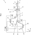
- the assembly line 1 may comprise a bonding device 14 that bonds the third web to the first web in a peripheral seam around the absorbent body so that the absorbent body 3 is enclosed within a closed volume defined by the topsheet, i.e. the first web, and the backsheet, i.e. the third web.
- the first web 6 then does not have to be attached to the absorbent body 3, but the absorbent body 3 may be kept in place by the closed volume being small enough to hinder any movement of the absorbent body 3.
- the assembly line 1 may also comprise a separating device 15 arranged to cut the laminate of webs 6, 7, 27 so that the absorbent article may be formed accordingly.
- the second web 7 is a continuous web the cutting device is also arranged to cut the second web accordingly.
- the assembly line may comprise a third camera 29 for controlling the third centre line of the third web 27.
- the third camera 29 together with a control device may be used in the same manner as been described above with reference to the first camera 22 and the second camera.
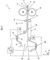
- Figure 3 schematically shows an embodiment of the invention where the absorbent article comprises only a backsheet 5 and an absorbent topsheet 4.
- the first web 6 then is a combination of a topsheet and absorbent body and the second web is the backsheet, or vice versa.
- the assembly line in figure 3 is identical to the assembly line in figures 1 and 2 with regard to the inventive process of alignment. The difference is that in figure 3 there is only the first web 6 and the second web 7 and the separating device 15 comprises two opposing rollers 30, each with a cutting edge 31.
- the separating device 15 is not restricted to rollers 30 but may be a shearing device or any other suitable separating device.
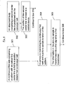
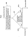
- Figure 4 shows Box 301-305.
- a continuous first web comprising a pattern with an optical first centre line is fed to a position distant from a conveyer belt.
- the first web is fed to the position by a first transport system according to figures 1-3 .
- the conveyer belt can be replaced by any other suitable means for transporting the second web allowing the first web to be placed onto the second web.
- a discontinuous second web in the form of a number of absorbent bodies is fed to the conveyer belt by a second transport system according to figures 1-3 .
- Each absorbent body comprises a second centre line and is positioned on the conveyer belt at a predetermined positioned. Go to BOx 303.
- the predetermined positioned may comprise a reference line that is to be aligned with the second centre line.
- the reference line may then be known to the control unit so that the position of the aligned second centre line becomes known.
- the second centre line may be known to the control device by an adaptive detector means that detects the lateral position of the second centre line relative the conveyer belt.
- the detector means may be a camera as explained in Box 304. Go to Box 310.
- a camera is monitoring the continuous first web and a picture sample is taken of the pattern.
- the picture is taken when the first web is positioned at a distance from the second web, i.e. before the first web is brought into contact with the second web.
- the camera is positioned before the marriage point, i.e. before the first web is brought into contact with the second web.
- the second camera is positioned closed to a first guidance device arranged to control the lateral position of the first web. Go to Box 305.
- the information in the picture sample is transformed into a first signal by a first transformer. Go to box 306
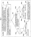
- FIG. 6 shows Box 306-307.
- the control device calculates the position of the first centre line in the first web from the information in the first signal.
- the control device may use any of the techniques described in connection to figures 1-3 . Go to Box 307.
- the control device After having decided on the position of the first centre line in the first web, the control device evaluates if the position of the first centre line is correct with relation to the second centre line.
- the second centre line is known to the control device.
- the control device uses the information regarding the difference ⁇ d in Box 307b to control the first guidance device to shift the position of the first web in a cross-machine direction so that the first centre line becomes aligned with the second centre line.
- the first web is attached to the second web. This can be done any known means, for example, welding, gluing, etc, which has been explained above. If a third web is comprised in the assembly on the opposite side of the absorbent article with relation to the first web, the attachment may be done indirectly by attaching the first web to the third web along the periphery of the absorbent body. However, the absorbent body may also be a part of the joint, i.e. the first web, the second web and the third web may be attached to each other.
- the first web is cut into pieces between the absorbent bodies. Hence, this operation separates the laminated web into absorbent articles.
- the cutting may be done by any known means and the laminated web may be cut along a selected profile so that the absorbent article is given a desired shape.
- Figures 7-9 show a flow chart of events taking place in Box 306 when deciding on if the first centre line is aligned with the second centre line.
- the control device has stored and is able to store a number of first id-signals representing a corresponding number of first pictures comprising correct and/or defect patterns in the first web.
- the wording "correct” and “defect” has been explained in connection to figures 1-3 .
- the control device compares information in the first signal of the most recent picture to the stored first id-signals for detection of a correct or defect pattern in the first web.
- the control device checks if the most recent first signal is represented in anyone of the stored id-signals.
- control device finds that the most recent first signal is not represented in anyone of the stored id-signals the control device checks if the most recent first signal is a pattern.
- the control device may alternatively or also comprise stored id-signals representing non-patterns, i.e. faulty patterns or patterns that for any reason has been chosen to be faulty. The control device can then use both faulty patterns and patterns for controlling the position of the first web.
- the pattern may be stored in the control device even though it is not the desired pattern or if it is a faulty pattern.
- an machine operator may decide that the picture, i.e. the most recent signal, is not a pattern but that it should be stored in the control device according to Box 601 and then go to Box 801.
- control device finds that the most recent first signal is represented in anyone of the stored id-signals the control device checks if the most recent first signal is a pattern or not.
- the position of the first centre line in the first web is calculated from the information in the most recent first signal. Go to Box 702.
- the control device can compare the new position with the former position of the first centre line, i.e. the previously calculated position, and can then evaluate if it is physically possible for the first centre line to have moved the calculated distance in the lateral direction. If this is not possible, the control device should disregard from the result and skip to the next picture, i.e. go to Box 304 for evaluation of a new picture; and if it is possible continue to Box 702.
Description
- The invention relates to an adaptive assembly line for assembly of a continuous first web to a continuous or discontinuous second web. The assembly line is arranged to feed the first and the second web in a machine direction. The assembly line comprises a control device comprising a camera that takes a first picture of the first web. The control device comprises a first transformer for transforming the first picture into a first signal. The control device is arranged to control the position of a first web with relation to a second web. The invention also relates to a method for an adaptive assembly line.
- When manufacturing absorbent articles such as diapers, sanitary napkins, incontinence protection article, etc., it is known to use a continuous conveyer belt onto which at least a part of the absorbent article is assembled. The sanitary napkin may comprise a topsheet, a backsheet and an absorbent body positioned therebetween. In the assembly line the absorbent body is positioned onto the conveyer belt and the topsheet is positioned onto the absorbent body. In the assembly line, the topsheet or the backsheet is in the form of a continuous web that is cut after being positioned onto the absorbent body.
- When the first web comprises a pattern the pattern has a first centre line that shall be positioned in line with a second centre line comprised in the absorbent body. It is important that the first centre line is an optic centre line, i.e. the first centre line shall be a centre line according to the eye of an observer. When the first web comprises an elastic material the shape and form of the first web may vary due to material variations and/or strains in the material caused, for example, by machine parts in the manufacturing plant. The machine parts may be rollers and stretchers, etc. arranged to bring the first web in a machine direction. When the first web changes form and shape the first centre line changes position, and as a consequence the position of the first centre line in relation to the second centre line is changed.
- It is common to use the first web as a topsheet and that the topsheet comprises two side portions of a first material and a centre portion of a second material therebetween. The centre portion is attached to the side portions by, for example, welding, gluing, mechanical bonding etc. and the attachment process forms seams that become part of or form the pattern of the first web. In the assembly line the seams run in the machine direction, i.e. in the feeding direction of the first and second webs. The position of the seams may vary somewhat with respect to the lateral side edges of the first web due to different factors such as material variations and external forces acting on the first web. The shifting of the position of the seams affects the position of the first centre line, i.e. the optic centre line. Each lateral side edge of the first web also has an extension in the machine direction and since the seams vary with respect to the lateral side edges, it is not a sufficiently good solution to calculate the first centre line from the position of one or both of the side edges since this obvious gives a wrong position of the first centre line in the first web.
-
US 2004/0028268 teaches a lamination process where a first web is laminated to a second web forming a composite web. The process comprises the use of a camera that periodically takes pictures of the composite web. The pictures are converted into electrical signals and are compared to a number of selected parameters in order to determine if the first web is properly aligned with the second web. A problem with the process according toUS 2004/0028268 is that the system detects a fault only after the composite web has been formed. The system allows for adjustment so that the fault is corrected, but the faulty part has to be rejected or accepted. - There is thus a need to control the first web in the lateral direction, i.e. in a direction being essentially perpendicular to the machine direction, so that the first centre line becomes aligned with the second centre line before assembly. The second centre line may be the centre line of a continuous web but may be the centre line of a broken web comprising a number of pieces of material arranged onto a conveyer belt. Document
JP 2007-169009 - The invention intends to remedy the above deficiencies and to find an adaptive assembly line for assembly of a continuous first web to a continuous or discontinuous second web according to
claim 1. One advantage of the invention is that a potential misalignment of the first centre line to the second centre line can be avoided before the assembly of the first web to the second web. In prior art detection system the camera is used to detect a faulty laminate, i.e. after assembly, which has to be rejected upon detection. - The control device is arranged to detect a pattern in the first web before assembly by use of the camera and a transformer that transforms a picture from the camera into electronic signals. The first camera is arranged to take pictures continuously or periodically.
- The control device uses a pattern detection system for detection of the pattern in one or many pictures. The pattern detection system is arranged to store signatures of the pattern in the first web for detection of the pattern in the picture and/or defect signatures of the pattern for detection of a faulty pattern in the first web. The pattern detection system may be arranged to identify one significant part of the pattern or a sequence of parts being a significant part of the pattern.
- The control device is arranged to calculate the position of the first centre line in the first web with regard to the pattern comprised in the first web. This is done after the detection of the pattern. The position of the first centre line can be calculated from the knowledge of the position of the pattern in the first picture since the camera advantageously is arranged in a fixed position relative the first web. The fixed position of the camera gives the possibility to define, for example, a grid pattern that can be used for defining the position of the first centre line and the second centre line. For example, a reference line can be arranged in the grid pattern, which reference line can be used for positioning the second web so that the second centre line is aligned with the reference pattern. The second centre line thus becomes known to the control device via the reference line before assembly so that the control device can calculate the misalignment between the first centre line and the second centre line before assembly.
- The first and the second centre lines extend essentially in the machine direction and the assembly line comprises a first guidance device arranged to shift the position of the first web in a cross-machine direction, i.e. in a lateral direction, for alignment of the first centre line with the second centre line before the assembly point.
- The first centre line is an optical centre line. The optical centre line can be defined as being a symmetrical line in a pattern where the symmetry lies in the eyes of a beholder. Hence, the first centre line shall be considered as a centre line in a pattern when a person is watching the pattern. The control device therefore comprises means for calculating the first centre line when the position of the pattern in the first web is known. The means for calculating may be an algorithm that can be programmed for the purpose.
- The invention is especially advantageous when the first web comprises, in a cross-machine direction, two side portions and a centre portion bonded together by two seams running in the machine direction. The pattern in the first web is here defined by the one of or both the two seams. The side portions are often made from a different material than the centre portion and for a number of reasons the seams may vary somewhat in position in the first web after bonding of the side portions and the central portion. The reasons may be a difference in the different material in different positions along the first web and may be a result of the process where machines transport the first web in the machine direction and therefore affects the first web with external forces. The present invention is adaptive to such variations and the control device continuously monitors any variations of lateral variations of the first centre line and controls the first guidance device accordingly.
- In one embodiment of the invention, the assembly line may comprise a conveyer belt for bringing the second web to the assembly point. The second web is positioned on the conveyer belt at a predetermined position. The use of a predetermined position assures that the control device has information regarding the position of the second centre line. The conveyer belt may for example comprise a reference line that is used when the second web is positioned on the conveyer belt. The second centre line is then aligned with the reference line. This embodiment is especially advantageous when the second web is a discontinuous web forming absorbent bodies that are to be laminated with the first web. The first web may then be a topsheet or a backsheet.
- In a further embodiment of the invention, a second camera is arranged to take second pictures of the second web. The assembly line comprises a second transformer for transforming the second pictures into a second signal. A control device is arranged to use the second signal for determining the position of the second centre line in the second web and the control device is arranged to use the second signal for controlling the position of the second web so that the second web is position at it predetermined position on the conveyer belt. The control device may be a separate control device with respect to the control device that controls the first web or may be a part of the same or may the same.
- However, the control device may be arranged to use the second signal for determining the position of the second centre line in the second web and the control device arranged to use the second signal for controlling the position of the first web and/or the second web so that the first centre line becomes aligned with the second centre line during assembly of the first web to the second web. This embodiment can be suitable when both the first web and the second web are continuous webs.
- The invention will below be described in connection to a number of drawings where:
-
Figure 1 schematically shows a top view of an adaptive assembly line according to the invention; -
Figure 2 schematically shows a side view of the assembly line according tofigure 1 according to a first embodiment of the invention; -
Figure 3 schematically shows a side view of the assembly line according tofigure 1 and according to a second embodiment of the invention, and where; -
Figures 4-9 schematically show a flow chart of a process according to the invention. -
Figure 1 schematically shows a top view of anadaptive assembly line 1 according to the invention. Theadaptive assembly line 1 is arranged to assemble anabsorbent article 2 comprising at least anabsorbent body 3 and atopsheet 4 and/or abacksheet 5. Theassembly line 1 is thus arranged to fit a continuousfirst web 6 to a continuous or discontinuoussecond web 7. Infigure 1 the continuousfirst web 6 is the topsheet and thesecond web 7 is a discontinuous web in the form of a number of absorbent bodies. Thefirst web 6 comprises a pattern 8 with an opticalfirst centre line 9 and thesecond web 7 comprises asecond centre line 10. Thefirst centre line 9 and thesecond centre line 10 extend in the machine direction. Here "machine direction" refers to the feeding direction of aconveyer belt 11 comprised in theassembly line 1. The purpose of theassembly line 1 is to bring thefirst centre line 9 into alignment with thesecond centre line 10. In order to explain the invention further, the wording "lateral direction" will be used when describing a cross-machine direction. In the figures, the machine direction is denoted with X and the lateral direction with Y. - In
figure 1 thefirst web 6 has been shown as being positioned on the side, Y-direction, of thesecond web 7 in order to more clearly describe the invention. As a consequence, the first web is shown in the figure in such a manner that it looks crooked, but this is only to be regarded as an optical illusion since thefirst web 6 advantageously is positioned above the second web as shown infigures 2 and3 . - The
assembly line 1 comprises anassembly station 12 comprising anassembly point 13, also known as marriage point, where thefirst web 6 is attached to thesecond web 7 when thefirst centre line 9 is aligned with thesecond centre line 10. Theassembly point 13 comprises abonding device 14 for bonding thefirst web 6 to thesecond web 7. The assembly line also comprises a separatingdevice 15 for separating thefirst web 6 into pieces. Infigure 1 theassembly line 1 comprises aconveyer belt 11 onto which thefirst web 6 and the second web are positioned for assembly. If thesecond web 7 would have been a continuous web theconveyer belt 11 could have been opted out and a different type ofassembly point 13 could have been chosen. For example, theassembly point 13 could be a roller or any moving surface that allows transportation of the first 6 and thesecond web 7 while thefirst web 6 is attached to thesecond web 7 with the bonding device. - In
figure 1 theassembly line 1 comprises afirst transport system 16 for feeding thefirst web 6 to theconveyer belt 11 and a second transport system for feeding thesecond web 7 to theconveyer belt 11. - The
first transport system 16 is a system for continuously feeding thefirst web 6 to the conveyer belt in the machine direction. Thefirst transport system 16 comprises a number of rollers over which thefirst web 6 is fed with a selected speed and tension. The first transport system comprises afirst guidance device 17 for controlling the lateral position of the first web over the rollers. Theassembly line 1 comprises acontrol device 18 for controlling thefirst guidance device 17 that controls the lateral position of the first web before the assembly point. - In
figure 1 , asecond transport system 19 is arranged for positioning of thesecond web 7 at a pre-selected position on theconveyer belt 11. Thesecond transport system 19 may be connected to thecontrol device 18 or may be connected to a separate control device (not shown). However, thecontrol device 18 of thefirst web 6 needs to comprise information on the position of thesecond centre line 10 in order to align thefirst centre line 9 with thesecond centre line 10. The pre-selected position may refer to areference line 20 in the conveyor belt running in the machine direction of theassembly line 1. When thesecond centre line 10 is positioned in alignment with thereference line 20 thesecond web 7 has been placed in the pre-selected position. Thereference line 20 is advantageously known to thecontrol device 18 and thecontrol device 18 thus assumes that thesecond web 7 is positioned in the pre-selected position and that thesecond centre line 10 is in alignment with thereference line 20. Hence, the position of thesecond centre line 10 is known to thecontrol device 18. Infigure 1 thesecond web 7 is a discontinuous web and thesecond transport system 19 is therefore arranged to feed a number ofabsorbent bodies 3 to the conveyer belt. However, if thesecond web 7 is a continuous web thesecond transport system 19 can be of the same type as thefirst transport system 16. Theassembly line 1 may comprise asecond guidance device 21 that controls the position of thesecond web 7 in theassembly point 13. Thesecond guidance device 21 may be controlled by thecontrol device 18 or a different control device (not show). Thesecond guidance device 21 is arranged to control the lateral Y position of the second web. Information regarding the position of thesecond centre line 10 may be fed continuously to thecontrol device 18 for control of the relative position of thefirst web 6 to thesecond web 7 by use of the first 17 andsecond guidance devices 21 respectively. - In
figure 1 thecontrol device 18 comprises afirst camera 22 that periodically or continuously takes a number of first pictures of thefirst web 6. Thecontrol device 18 also comprises a first transformer for transforming the first pictures into a corresponding number of first signals. Thecontrol device 18 is arranged to control the position of thefirst centre line 9 in thefirst web 6 with relation to thesecond centre line 10 of thesecond web 7. It is an object of the invention to continuously bring thefirst centre line 9 in alignment with thesecond centre line 10. Thefirst camera 22 is therefore arranged to take the first pictures before assembly of thefirst web 6 to thesecond web 7. The closer thefirst camera 22 is positioned to thefirst guidance device 17 the quicker the response when a change in thefirst centre line 9 is detected. Here, "response" refers to the control of the lateral position of thefirst web 6 by use of the first guidance device. - The
control device 18 is arranged to use the first signal for determining the lateral position of thefirst centre line 9 in thefirst web 6. Thefirst centre line 9 may vary somewhat due to a number of different factors. For example, one factor is different thickness of thefirst web 6 which gives different elastic properties which gives a movement in thefirst web 6 that changes the position of thefirst centre line 9; another factor is that the first transport system has flaws, i.e. is not perfect, and therefore applies different forces on different parts of thefirst web 6 which causes movement within thefirst web 6 which changes the position of thefirst centre line 9. - The position of the
first centre line 9 is determined by the aid of a picture recognizing system that transforms the first picture into a first signal, preferably an electrical signal. The first signal comprises information regarding any pattern 8 comprised in the first picture. For example, a certain pattern 8 in thefirst web 6 may be developed in the picture as being darker or brighter than its surroundings, i.e. there exists a number of different contrasts in a black and white photo. The difference in contrast (or colour if the picture is a colour picture) in the picture gives a signature in the first signal that differs from a signature caused by a non-patterned surface. The picture recognizing system scans the picture in a selected way and logs position and corresponding signatures and can therefore be used for identifying the pattern 8 and for calculating thefirst centre line 9 of thefirst web 6. Thefirst centre line 9 may be calculated from a mean value in the first signal or a position between certain values, but may be calculated by use of any suitable method. Thefirst centre line 9 is an optical centre line. Here "optic centre line" means that the eye of a human observer recognizes the first centre line to be the centre line of the pattern 8 in the first web. Hence, thefirst centre line 9 need not be a mathematically correct average or mean value of the pattern 8 but may be the centre line from an artistic point of view. Thefirst centre line 9 may therefore be a symmetric centre line with regard to the pattern 8. Thecontrol device 18 may comprise one or many stored prepared signatures, i.e. id-signals, that identify the pattern in the first picture i.e. in thefirst web 6. The most recent first picture is then compared to the stored pictures, i.e. id-signals, in order to find a match and to thereby give the control device information on if a pattern 8 has been found or not. If a pattern 8 has been found the position of thefirst centre line 9 in thefirst web 6 is calculated in thecontrol device 18 by use of the detected position of the pattern. It should be noted that it is not possible to calculate thefirst centre line 9 from detection of the lateral side edges 23 of thefirst web 6 since the pattern 8 in thefirst web 6 may vary in the lateral direction within thefirst web 6, which gives afirst centre line 9 that varies dependent on the pattern 8 and not on the lateral side edges 23. Here "lateral side edges" refer to the side edges 23 of thefirst web 6 that have an extension in the machine direction X. - The
control device 18 is arranged to use the first signal for controlling the position of thefirst web 6 and/or thesecond web 7 so that thefirst centre line 9 becomes aligned with thesecond centre line 10 during assembly of thefirst web 6 to thesecond web 7. This means that after the position of thefirst centre line 9 in the first web has been calculated thecontrol device 18 uses the information together with information regarding the position of thesecond centre line 10, i.e., e.g. thereference line 20, in order to calculate any misalignment Δd between thefirst centre line 9 and thesecond centre line 10. The misalignment Δd is interpreted by thecontrol device 18 so that thecontrol device 18 can control thefirst web 6 and/or thesecond web 7 in the lateral direction, i.e. in a cross-machine direction Y being essentially perpendicular to the machine direction X. - The problem with a travelling
first centre line 9, i.e. movement in the cross-machine direction, is especially common when thefirst web 6 comprises, in the cross-machine direction Y, twoside portions 24 and acentre portion 25 bonded together by twoseams 26 in the machine direction X. Here, the pattern 8 comprises the twoseams 26 and thefirst centre line 9 shall be calculated with regard to theseams 26. Thecentre portion 25 is often made from a different material than theside portions 24 which can give different stretch of the different materials in different portions of thefirst web 6 which gives that the position of theseams 26 varies within thefirst web 6. Furthermore, even though the twoseams 26 are often made in a device that performs bonding of the twoseams 26 simultaneously and at the same distance, the lateral position of thefirst centre line 9 may vary since theside portions 24 and thecentre portion 25 may have different properties and may thus affect the position of the seams differently. However, thefirst camera 22 andcontrol device 18 may be arranged for detection of one or both theseams 26 for calculating thefirst centre line 9. In both cases, thefirst centre line 9 may be positioned at half the distance from one of theseams 26, i.e. in the middle of theseams 26. The best result is thus achieved when bothseams 26 are detected since a more exact position of thefirst centre line 9 can be calculated. However, detection of oneseam 26 together with an estimate of the lateral position of the first centre line is an improvement over the previously known control device where the position of thelateral side edge 23 are detected and used for control. Detection of oneseam 26 together with an estimate of the lateral position of thefirst centre line 9 can advantageously be used, for example, when the other seam has been executed but the pattern of the second seam for some reason has been less visible. This can happen, for example, when an ultrasonic welding device is used for welding and where the seams comprise a number of embossed indentations that constitute the bonding areas of theseam 26. The embossed pattern may be less visible on oneseam 26 than the other, but both theseams 26 may be adequately formed as such. The process should therefore be allowed, at least for a short while, because the pattern 8 may be weak only for a short period of time. - In
figure 1 , thecontrol device 18 is arranged to store previous pictures of the pattern 8 in the first web. The pictures are converted into identity signals (hereinafter called id-signals or signatures) that are used for identification of the pattern 8 in the first picture. The stored id-signals can be both identifications of correct patterns and identification of a defect or wrong pattern. The stored correct id-signal may be in the form of an allowable range representing different variants of the correct pattern. The range can be in the form of a number of id-signals representing a number of pictures and patterns, but can also be a numerical range. The advantage of using a range is that the control device can recognize a correct pattern even if the pattern differs somewhat over time, but within the allowable range. - Here "defect" refers to a selected pattern that is not allowed. The
control device 18 uses the stored defect pictures to recognise an already known and processed defect picture. The control device may use this information for activating an action plan, for example, alert an operator and/or stop the assembly line or any other suitable action plan that can be used to rectify the detected defect. - It should be noted that the pattern 8 that is to be identified can be a part of a larger pattern, for example a smaller part of one or both seams; or may be the entire pattern over a selected area of the first web. The entire pattern may thus be one of or both the seams over a selected area in the machine direction.
- The
control device 18 is advantageously arranged to calculate the lateral position of the pattern 8 in thefirst web 6 when the pattern 8 has been detected. For example, the lateral position can be calculated from information extracted from the first picture. As mentioned before, the first picture is converted into an electrical first signal and this can be done by, for example, breaking down the picture into a number of discrete elements that are investigated. Here "investigated" means that the control device converts the discrete element into electrical signals that represent the discrete element. Thecontrol device 18 also chooses an order in which the discrete elements are investigated. The described investigation is commonly referred to as scanning, but other methods for investigating the picture can be used. The first picture is then investigated in the same manner and is compared to the stored id-signals. When thecontrol device 18 has detected the existence of the pattern the position of the pattern can be calculated by comparing the position of the detected pattern 8 in the picture. - The
control device 18 uses the information regarding the lateral position of the pattern to calculate the first centre line and to control the position of the first 6 and/orsecond web 7 so that the first centre line is brought into alignment with thesecond centre line 10. - The
control device 18 may advantageously comprise a logic unit that performs various mathematical tasks that are used for pattern detection purposes and control purposes according to an algorithm. The logic unit may, for example, be arranged to keep track of the lateral position of the pattern, i.e. one of or both the seams. If the lateral position of the pattern 8 suddenly alters above a selected threshold, the logic unit may be arranged to ignore the information as being a faulty detection of the pattern and may be arranged to either investigate the first picture again or investigate the next picture. - In one embodiment of the invention, the
assembly line 1 comprises a second camera (not shown) that can be arranged to take second pictures of the second web. Theassembly line 1 then comprises a second transformer for transforming the second pictures into a second signal. Thecontrol device 18 is arranged to use the second signal for determining the position of thesecond centre line 10 in the second web and thecontrol device 18 is arranged to use the second signal for controlling a second guidance device that controls the lateral position of the second web so that thefirst centre line 9 becomes aligned with thesecond centre line 10 during assembly of thefirst web 6 to thesecond web 7. - In another embodiment of the invention, the
assembly line 1 comprises a third camera (29;figures 2 and3 ) that can be arranged to take third pictures of athird web 27. Theassembly line 1 then comprises a third transformer for transforming the third pictures into a third signal. Thecontrol device 18 is arranged to use the third signal for determining the position of a third centre line (not shown) in thethird web 27 and thecontrol device 18 is arranged to use the third signal for controlling athird guidance device 28 that controls the lateral position of thethird web 27 so that the first centre line becomes aligned with the second centre line and the third centre line during assembly of the first web to the second web. - In
figure 1 thefirst web 6 is a continuous topsheet and the second web in the form of discrete absorbent bodies and the third web a continuous backsheet. Advantageously, theconveyer belt 11 is fixed in its position and comprises areference line 20 known to thecontrol device 18. The positioning of the second 7 andthird web 27 onto theconveyer belt 11 is made to thisreference line 20 by use of the second 21 and third guidance devices respectively. Thefirst web 6 is then positioned onto theabsorbent bodies 3 so that the first centre line is aligned with thesecond centre line 10. Hence, the first centre line becomes aligned with the reference line. - It should be noted that the
control device 18 may control thefirst web 6 only and that one or several further control devices may be comprised in theassembly line 1 for controlling thesecond web 7 and/or thethird web 27. The further control device(s) may thus operate independently from thecontrol device 18 controlling the first web and may operate independently of each other when a reference line is used. The control devices may also be arranged for intercommunication for control of the assembly line. - The
first camera 22 described in connection tofigure 1 periodically takes pictures of the first web with a sampling frequency that is dependent on the feeding speed of the first web and the processing speed of thecontrol device 18. The faster the feeding speed the higher the frequency. However, thefirst camera 22 may take pictures continuously, i.e. may film the first web with an open shutter and the control device may then draw sample pictures from the film or may calculate continuously should the processor in the first transformer and in the control device be arranged to handle such continuous processes. Here "open shutter" refers to the use of a camera comprising mechanical parts, but when using digital cameras or another technique the shutter is replaced by a different device that allows for light to enter a recording medium, for example a chemical film or a digital or magnetic recording device. The second and/or the third camera(s) may be arranged in the same manner as the first camera. -
Figure 1 shows that thefirst camera 22 takes a first picture of a first area of the first web before theassembly point 13. As been explained before the assembly point is the area in which the first web is attached to the second web. Infigure 1 the projection path of thefirst camera 22 is marked with broken lines in order to facilitate the description of the invention. In the first area is shown that thefirst centre line 9 is not aligned with thesecond centre line 10. The difference is marked with Δd and is a measure c2-c1 of how much thefirst web 6 or thesecond web 7 has to be moved in order for thefirst centre line 9 to become aligned with thesecond centre line 10. Here "c1" refers to thefirst centre line 9 and "c2" to thesecond centre line 10. The control device calculates Δd from information in the first picture and information regarding the position of the second centre line. Thecontrol device 18 uses the information to control thefirst guidance device 17 that is arranged to alter the path of the first web in the cross-machine direction with a distance corresponding to Δd. - In
figure 1 is shown that after theassembly point 13 thefirst centre line 9 is aligned with thesecond centre line 10.Figure 1 also shows a first centre line 9' potentially misaligned with thesecond centre line 10 and a corresponding misalignment distance Δd' that would have been the consequence if the lateral position of the first web had not been shifted before the assembly point. -
Figure 2 schematically shows a side view of theassembly line 1 according tofigure 1 .Figure 2 shows that theassembly point 13 comprises abonding device 14 in the form of a set of rollers. The rollers presses together selected portions of the first and the second web. The selected portions are then bonded together by use of any suitable means known in the art. The rollers may for example comprise means for ultrasonic bonding and/or mechanical bonding and/or heat bonding. However, the rollers may be replaced by any other suitable device for bonding together the first and the second web when the first web is moving, for example, an ultrasonic welding device or mechanical bonding device or a welding device. The welding device can be a laser device or another type of heating device. - The rollers may be used as a separating device for separating the first web into pieces. The rollers may comprise cutting edges formed in a selected pattern that cuts the first web during rotation of the rollers. Each piece is preferably in a shape that corresponds to the shape of the absorbent body or in any other selected form. In
figure 2 theseparating device 15 is a unit separate from thebonding device 14. The separatingdevice 15 may be positioned in connection to thebonding device 14 or after thebonding device 14. The separatingdevice 15 may be a cutting device or a shearing device or any other device suitable for separating the laminate of webs when the webs are moving. Here the "laminate" may comprise thefirst web 6 and/or thesecond web 7 and/or thethird web 27. Infigure 2 theseparating device 15 performs a linear movement for cutting, but the separating device may comprise two opposing rollers comprising cutting or shearing edges (seefigure 3 ) that rotates with the layered first 6, second 7 andthird webs 27 in the machine direction and cuts the layered web upon rotation. - The
assembly line 1 may comprise abonding device 14 that bonds the third web to the first web in a peripheral seam around the absorbent body so that theabsorbent body 3 is enclosed within a closed volume defined by the topsheet, i.e. the first web, and the backsheet, i.e. the third web. Thefirst web 6 then does not have to be attached to theabsorbent body 3, but theabsorbent body 3 may be kept in place by the closed volume being small enough to hinder any movement of theabsorbent body 3. Theassembly line 1 may also comprise aseparating device 15 arranged to cut the laminate ofwebs second web 7 is a continuous web the cutting device is also arranged to cut the second web accordingly. - The assembly line may comprise a
third camera 29 for controlling the third centre line of thethird web 27. Thethird camera 29 together with a control device may be used in the same manner as been described above with reference to thefirst camera 22 and the second camera. -
Figure 3 schematically shows an embodiment of the invention where the absorbent article comprises only abacksheet 5 and anabsorbent topsheet 4. Thefirst web 6 then is a combination of a topsheet and absorbent body and the second web is the backsheet, or vice versa. The assembly line infigure 3 is identical to the assembly line infigures 1 and2 with regard to the inventive process of alignment. The difference is that infigure 3 there is only thefirst web 6 and thesecond web 7 and the separatingdevice 15 comprises two opposingrollers 30, each with acutting edge 31. As mentioned in connection tofigure 1 and2 , the separatingdevice 15 is not restricted torollers 30 but may be a shearing device or any other suitable separating device. -
Figures 4-9 schematically show a flow chart of a process according to the invention. -
Figure 4 shows Box 301-305. - A continuous first web comprising a pattern with an optical first centre line is fed to a position distant from a conveyer belt. The first web is fed to the position by a first transport system according to
figures 1-3 . It should be noted the conveyer belt can be replaced by any other suitable means for transporting the second web allowing the first web to be placed onto the second web. Go toBox 304 - A discontinuous second web in the form of a number of absorbent bodies is fed to the conveyer belt by a second transport system according to
figures 1-3 . Each absorbent body comprises a second centre line and is positioned on the conveyer belt at a predetermined positioned. Go toBOx 303. - By positioning the second web at a predetermined position the position of the second centre line becomes known to a control device. The predetermined positioned may comprise a reference line that is to be aligned with the second centre line. The reference line may then be known to the control unit so that the position of the aligned second centre line becomes known. In another embodiment, the second centre line may be known to the control device by an adaptive detector means that detects the lateral position of the second centre line relative the conveyer belt. The detector means may be a camera as explained in
Box 304. Go toBox 310. - A camera is monitoring the continuous first web and a picture sample is taken of the pattern. The picture is taken when the first web is positioned at a distance from the second web, i.e. before the first web is brought into contact with the second web. Hence, the camera is positioned before the marriage point, i.e. before the first web is brought into contact with the second web. Advantageously, the second camera is positioned closed to a first guidance device arranged to control the lateral position of the first web. Go to
Box 305. - The information in the picture sample is transformed into a first signal by a first transformer. Go to
box 306 -
Figure 6 shows Box 306-307. - The control device calculates the position of the first centre line in the first web from the information in the first signal. The control device may use any of the techniques described in connection to
figures 1-3 . Go toBox 307. - After having decided on the position of the first centre line in the first web, the control device evaluates if the position of the first centre line is correct with relation to the second centre line. The second centre line is known to the control device.
- If the answer to the question in
Box 307 is yes, then go toBox 310 If the answer is yes the control device does not have to change the position of the first centre line in relation to the second centre line since they are already aligned. - If the answer to the question in
Box 307 is no, go toBox 308. If the answer is no the control device has to change the position of the first centre line in relation to the second centre line so that they become aligned. -
Figure 6 shows Box 308-312: - The control device calculates the difference Δd in alignment between the first centre line and the second centre line of the absorbent body.
- The control device uses the information regarding the difference Δd in
Box 307b to control the first guidance device to shift the position of the first web in a cross-machine direction so that the first centre line becomes aligned with the second centre line. - The continuous first web is positioned over the absorbent body. The first web is thus positioned at a distance above the second web before the second web is brought into contact with the second web.
- The first web is attached to the second web. This can be done any known means, for example, welding, gluing, etc, which has been explained above. If a third web is comprised in the assembly on the opposite side of the absorbent article with relation to the first web, the attachment may be done indirectly by attaching the first web to the third web along the periphery of the absorbent body. However, the absorbent body may also be a part of the joint, i.e. the first web, the second web and the third web may be attached to each other.
- The first web is cut into pieces between the absorbent bodies. Hence, this operation separates the laminated web into absorbent articles. The cutting may be done by any known means and the laminated web may be cut along a selected profile so that the absorbent article is given a desired shape.
-
Figures 7-9 show a flow chart of events taking place inBox 306 when deciding on if the first centre line is aligned with the second centre line. -
Figure 7 : - The control device has stored and is able to store a number of first id-signals representing a corresponding number of first pictures comprising correct and/or defect patterns in the first web. The wording "correct" and "defect" has been explained in connection to
figures 1-3 . - The control device compares information in the first signal of the most recent picture to the stored first id-signals for detection of a correct or defect pattern in the first web.
- The control device checks if the most recent first signal is represented in anyone of the stored id-signals.
- If the answer to the question in
Box 603 is no then go toBox 604. Here, the most recent first signal is neither identified as a correct pattern nor identified as a defect pattern. - If the answer to the question in
Box 603 is yes then go toBox 605. - Is it a pattern ? If the control device finds that the most recent first signal is not represented in anyone of the stored id-signals the control device checks if the most recent first signal is a pattern. As been mentioned above in connection to
Box 601, the control device may alternatively or also comprise stored id-signals representing non-patterns, i.e. faulty patterns or patterns that for any reason has been chosen to be faulty. The control device can then use both faulty patterns and patterns for controlling the position of the first web. - If the answer to the question in
Box 604 is no go toBox 801. As mentioned above in connection toBox 604, the pattern may be stored in the control device even though it is not the desired pattern or if it is a faulty pattern. Here, an machine operator may decide that the picture, i.e. the most recent signal, is not a pattern but that it should be stored in the control device according toBox 601 and then go toBox 801. There may also be other alternatives than to use a person to find out whether the most recent signal should be recognized as a faulty pattern, for example an automatic detection system. - If the answer to the question in
Box 604 is yes go toBox 606. Here, an machine operator may decide that the picture, i.e. the most recent signal, is a pattern. There may also be other alternatives than to use a person to find out whether the most recent signal should be recognized as a pattern, for example an automatic detection system. - Is it a pattern ? If the control device finds that the most recent first signal is represented in anyone of the stored id-signals the control device checks if the most recent first signal is a pattern or not.
- If the answer to the question in
Box 605 is no go toBox 801. - If the answer to the question in
Box 604 is yes go toBox 701 - Store the most recent first signal in the control device according to
Box 601 and go toBox 701 -
Figure 8 : - The position of the first centre line in the first web is calculated from the information in the most recent first signal. Go to
Box 702. Here, the control device can compare the new position with the former position of the first centre line, i.e. the previously calculated position, and can then evaluate if it is physically possible for the first centre line to have moved the calculated distance in the lateral direction. If this is not possible, the control device should disregard from the result and skip to the next picture, i.e. go toBox 304 for evaluation of a new picture; and if it is possible continue to Box 702. - Store the position of the first centre line in the first web in the control device together with the corresponding first signal. Go to
Box 307 -
Figure 9 : - Check new picture? If the control device finds that the most recent first signal is not represented in anyone of the stored id-signals and that it is not a pattern according to
box 604a an action plan is required. If the control device finds that the most recent first signal is represented in anyone of the stored id-signals and that it is not a pattern there still exists a need for an action plan. The action plan I here to decide whether to continue with the production or not. The basic question to investigate is thus whether if the most recent picture should be disregarded and a new picture should be examined? - If the answer to the question in
Box 801 is no go toBox 802. Hence, if the result from the investigation of the most recent first picture is valid and a new picture shall not be examined instead, an action plan is needed in order to decide whether to stop the assembly line or not. - If the answer to the question in
Box 801 is yes go toBox 304. Hence if the result from the investigation of the most recent first picture is regarded as faulty a new picture shall be examined instead, an action plan is need in order to decide whether to stop the assembly line or not. If the response time for the control device is quick with relation to the speed of the assembly line, a new picture or a number of new pictures may be examined according toBox 304 in order to find out if the last one was faulty before deciding to stop the assembly line.
Claims (18)
- An adaptive assembly line (1) for assembly of a continuous first web (6) to a continuous or discontinuous second web (7), the assembly line (1) being arranged to feed the first and the second web (7) in a machine direction (X), the assembly line (1) comprising a control device (18) comprising a first camera (22) arranged to take a first picture of the first web (6), the control device comprising a first transformer for transforming the first picture into a first signal, the control device (18) being arranged to control the position of the first web (6) with relation to the second web (7), characterized in that the first camera (22) is arranged to take the pictures before assembly of the first web (6) to the second web (7) and that the control device (18) is arranged to use the first signal for determining the position of a first centre line (9) in the first web by detecting a pattern (8) in the first web (6) and that the control device (18) is arranged to calculate the position of the first centre line (9) in the first web (6) with regard to the pattern (8) comprised in the first web (6) and that the control device (18) is arranged to use the first signal for controlling the position of the first web (6) and/or the second web (7) so that the first centre line becomes aligned with a second centre line (10) comprised in the second web (7) during assembly of the first web (6) to the second web (7), wherein the second centre line (10) is known to the control device (18) before assembly.
- An adaptive assembly line (1) according to claim 1, characterized in that the first centre line (9) is an optical centre line.
- An adaptive assembly line (1) according to any one of the preceding claims, characterized in that the control device (18) is arranged to store signatures of the pattern (8) in the first web (6) for detection of the pattern in the first picture and/or defect signatures of the pattern (8) for detection of a faulty pattern in the first web.
- An adaptive assembly line (1) according to any one of the preceding claims, characterized in that the first camera (22) is arranged to take pictures continuously or periodically.
- An adaptive assembly line (1) according to any one of the preceding claims, characterized in that the first and the second centre lines (9, 10) extend in the machine direction (X).
- An adaptive assembly line (1) according to any one of the preceding claims, characterized in that assembly line comprises a conveyer belt (11) and that the second web is positioned on the conveyer belt (11).
- An adaptive assembly line (1) according to any one of the preceding claims, characterized in that the control device (18) is arranged to control the first web (6) in a cross-machine direction (Y) being essentially perpendicular to the machine direction (X).
- An adaptive assembly line (1) according to any one of the preceding claims, characterized in that a second camera is arranged to take second pictures of the second web (7), the assembly line (1) comprising a second transformer for transforming the second pictures into a second signal, the control device (18) being arranged to use the second signal for determining the position of the second centre line (10) in the second web (7) and that the control device (18) is arranged to use the second signal for controlling the position of the first web (6) and/or the second web (7) so that the first centre line (9) becomes aligned with the second centre line (10) during assembly of the first web to the second web.
- A system comprising an adaptive assembly line (1) according to any of the preceding claim and a first web (6), characterized in that the first web (6) comprises, in a cross-machine direction, two side portions (24) and a centre portion (26) bonded together by two seams (26) in the machine direction (X), wherein the pattern (8) comprises one of or both the two seams (26).
- A method for an adaptive assembly line (1) for assembly of a continuous first web (6) to a continuous or discontinuous second web (7), the assembly line (1) feeds the first and the second web (7) in a machine direction (X), the assembly line (1) comprising a control device (18) comprising a first camera (22) that takes a first picture of the first web (6), the control device comprising a first transformer for transforming the first picture into a first signal, the control device (18) controlling the position of the first web (6) with relation to the second web (7), characterized in that the first camera (22) is arranged to take the pictures before assembly of the first web (6) to the second web (7) and that the control device (18) is arranged to use the first signal for determining the position of a first centre line (9) in the first web by detecting a pattern (8) in the first web (6) and that the control device (18) is arranged to calculate the position of the first centre line (9) in the first web (6) with regard to the pattern (8) comprised in the first web (6) and that the control device (18) is arranged to use the first signal for controlling the position of the first web (6) and/or the second web (7) so that the first centre line becomes aligned with a second centre line (10) comprised in the second web (7) during assembly of the first web (6) to the second web (7), wherein the second centre line (10) is known to the control device (18) before assembly.
- A method according to claim 10, characterized in that the first web (6) comprises, in a cross-machine direction, two side portions (24) and a centre portion (26) bonded together by two seams (26) in the machine direction (X), wherein the pattern (8) comprises one of or both the two seams (26).
- A method according to any one of claims 10-11, characterized in that the first centre line (9) is an optical centre line.
- A method according to any one of claims 11-12, characterized in that the control device (18) stores signatures of the pattern (8) in the first web (6) for detection of the pattern in the first picture and/or defect signatures of the pattern (8) for detection of a faulty pattern in the first web.
- A method according to any one of claims 11-13, characterized in that the first camera (22) takes pictures continuously or periodically.
- A method according to any one of claims 11-14, characterized in that the first and the second centre lines (9, 10) extend in the machine direction (X).
- A method according to any one of claims 11-15, characterized in that assembly line comprises a conveyer belt (11) and that the second web is positioned on the conveyer belt (11).
- A method according to any one of claims 11-16, characterized in that the control device (18) controls the first web (6) in a cross-machine direction (Y) being essentially perpendicular to the machine direction (X).
- A method according to any one of claims 11-17, characterized in that a second camera takes second pictures of the second web (7), the assembly line (1) comprising a second transformer for transforming the second pictures into a second signal, the control device (18) using the second signal for determining the position of the second centre line (10) in the second web (7) and that the control device (18) uses the second signal for controlling the position of the first web (6) and/or the second web (7) so that the first centre line (9) becomes aligned with the second centre line (10) during assembly of the first web to the second web.
Applications Claiming Priority (2)
| Application Number | Priority Date | Filing Date | Title |
|---|---|---|---|
| GB0716782A GB2457009A (en) | 2007-08-29 | 2007-08-29 | Method for controlling a web |
| PCT/SE2008/000480 WO2009029017A1 (en) | 2007-08-29 | 2008-08-28 | Device and method for controlling a web |
Publications (3)
| Publication Number | Publication Date |
|---|---|
| EP2190765A1 EP2190765A1 (en) | 2010-06-02 |
| EP2190765A4 EP2190765A4 (en) | 2017-09-27 |
| EP2190765B1 true EP2190765B1 (en) | 2018-06-13 |
Family
ID=38616920
Family Applications (1)
| Application Number | Title | Priority Date | Filing Date |
|---|---|---|---|
| EP08794106.8A Not-in-force EP2190765B1 (en) | 2007-08-29 | 2008-08-28 | Device and method for controlling a web |
Country Status (6)
| Country | Link |
|---|---|
| US (1) | US8447425B2 (en) |
| EP (1) | EP2190765B1 (en) |
| JP (1) | JP5264910B2 (en) |
| CN (1) | CN101795949B (en) |
| GB (1) | GB2457009A (en) |
| WO (1) | WO2009029017A1 (en) |
Families Citing this family (5)
| Publication number | Priority date | Publication date | Assignee | Title |
|---|---|---|---|---|
| JP5647846B2 (en) * | 2010-09-30 | 2015-01-07 | ユニ・チャーム株式会社 | Kneading and stretching method for continuous sheet composite and absorbent sheet for absorbent article |
| BR112013030032A2 (en) * | 2011-05-25 | 2016-09-13 | Procter & Gamble | manufacturing system and method using a virtual reference structure |
| JP5786056B1 (en) * | 2014-03-27 | 2015-09-30 | ユニ・チャーム株式会社 | Absorbent article manufacturing apparatus and absorbent article manufacturing method |
| CN109677102A (en) * | 2019-02-21 | 2019-04-26 | 南京赛旺科技发展有限公司 | A kind of synchronizing to flower method and system for calender |
| MX2021010513A (en) * | 2019-03-01 | 2021-10-01 | Paper Converting Machine Co | Rewinder winding methods and apparatus. |
Family Cites Families (15)
| Publication number | Priority date | Publication date | Assignee | Title |
|---|---|---|---|---|
| US4888717A (en) * | 1984-11-02 | 1989-12-19 | Adolph Coors Company | Web lateral position control apparatus and method |
| JPH095020A (en) * | 1995-06-16 | 1997-01-10 | Kanegafuchi Chem Ind Co Ltd | Meandering correction device and lamination device in combination therewith |
| US5689340A (en) * | 1995-12-06 | 1997-11-18 | Eastman Kodak Company | Apparatus and method for measuring alignment in lenticular media |
| GB2318084B (en) * | 1996-10-14 | 1998-09-09 | Tecksom International Limited | Laminating apparatus |
| US6856859B1 (en) * | 1998-12-31 | 2005-02-15 | Kimberly-Clark Worldwide, Inc. | Method of controlling cross-direction alignment in manufacturing process |
| JP3351763B2 (en) * | 1999-07-19 | 2002-12-03 | 花王株式会社 | Manufacturing method of absorbent article |
| US6743324B2 (en) * | 2001-09-17 | 2004-06-01 | The Procter & Gamble Company | Method for manufacturing shaped components from web materials |
| US6900450B2 (en) * | 2002-03-09 | 2005-05-31 | Kimberly-Clark Worldwide, Inc. | Method and apparatus for inferring item position based on multiple data |
| US6845283B2 (en) * | 2002-07-26 | 2005-01-18 | Kimberly-Clark Worldwide, Inc. | Process and apparatus for making articles |
| US7171283B2 (en) * | 2002-08-07 | 2007-01-30 | Kimberly-Clark Worldwide, Inc. | Web guiding system and method |
| JP4503929B2 (en) * | 2003-01-14 | 2010-07-14 | ユニ・チャーム株式会社 | Method for guiding side edges of continuously running web and apparatus therefor |
| DE602004027222D1 (en) | 2003-03-27 | 2010-07-01 | Zuiko Corp | FOLDING MACHINE AND METHOD FOR PRODUCING FASTENING ARTICLES |
| US20050241774A1 (en) * | 2004-04-30 | 2005-11-03 | Kimberly-Clark Worldwide, Inc. | Apparatus and process for aligning materials during a splice |
| JP4376201B2 (en) | 2005-04-05 | 2009-12-02 | 花王株式会社 | Conveying composite sheet position control method |
| JP2007169009A (en) * | 2005-12-22 | 2007-07-05 | Kao Corp | Manufacturing method and manufacturing device of composite sheet and article |
-
2007
- 2007-08-29 GB GB0716782A patent/GB2457009A/en active Pending
-
2008
- 2008-08-28 CN CN2008801044090A patent/CN101795949B/en not_active Expired - Fee Related
- 2008-08-28 US US12/675,404 patent/US8447425B2/en active Active
- 2008-08-28 WO PCT/SE2008/000480 patent/WO2009029017A1/en active Application Filing
- 2008-08-28 JP JP2010522858A patent/JP5264910B2/en not_active Expired - Fee Related
- 2008-08-28 EP EP08794106.8A patent/EP2190765B1/en not_active Not-in-force
Non-Patent Citations (1)
| Title |
|---|
| None * |
Also Published As
| Publication number | Publication date |
|---|---|
| EP2190765A4 (en) | 2017-09-27 |
| EP2190765A1 (en) | 2010-06-02 |
| GB0716782D0 (en) | 2007-10-10 |
| WO2009029017A9 (en) | 2010-02-04 |
| JP5264910B2 (en) | 2013-08-14 |
| WO2009029017A1 (en) | 2009-03-05 |
| US20100212136A1 (en) | 2010-08-26 |
| US8447425B2 (en) | 2013-05-21 |
| GB2457009A (en) | 2009-08-05 |
| CN101795949B (en) | 2013-12-25 |
| CN101795949A (en) | 2010-08-04 |
| JP2010537917A (en) | 2010-12-09 |
Similar Documents
| Publication | Publication Date | Title |
|---|---|---|
| US8273003B2 (en) | Web folding apparatus, web folding method, and worn article producing method | |
| EP2190765B1 (en) | Device and method for controlling a web | |
| USRE48182E1 (en) | Apparatus and method for minimizing waste and improving quality and production in web processing operations by automatic cuff defect correction | |
| US11051992B2 (en) | Systems and methods for inspecting absorbent articles on a converting line | |
| US8007623B2 (en) | Apparatus and method for intermittent application of stretchable web to target web | |
| EP1270480B1 (en) | Method and apparatus for producing disposable worn article or garment | |
| US9387131B2 (en) | Apparatus and method for minimizing waste and improving quality and production in web processing operations by automated threading and re-threading of web materials | |
| JP4952550B2 (en) | Carrier film wrinkle detection apparatus and method | |
| US7809179B2 (en) | Manufacturing inspection of folded feminine hygiene products by cascading edge and skew detection | |
| JP2007169009A (en) | Manufacturing method and manufacturing device of composite sheet and article | |
| US20210300707A1 (en) | Apparatus and method for web twist defect correction | |
| US20050239621A1 (en) | Method for monitoring the position of a sheet transported in a folding machine | |
| EP1265728B1 (en) | System for measuring and controlling cut length of discrete components in a high-speed process | |
| US20120260813A1 (en) | Method and device for measuring a running direction of a substrate web | |
| JP2001273540A (en) | Examination device for paper sheets | |
| JPH09301598A (en) | Paper sheet processing device and controlling method for paper sheet processing device |
Legal Events
| Date | Code | Title | Description |
|---|---|---|---|
| PUAI | Public reference made under article 153(3) epc to a published international application that has entered the european phase |
Free format text: ORIGINAL CODE: 0009012 |
|
| 17P | Request for examination filed |
Effective date: 20100318 |
|
| AK | Designated contracting states |
Kind code of ref document: A1 Designated state(s): AT BE BG CH CY CZ DE DK EE ES FI FR GB GR HR HU IE IS IT LI LT LU LV MC MT NL NO PL PT RO SE SI SK TR |
|
| AX | Request for extension of the european patent |
Extension state: AL BA MK RS |
|
| RIN1 | Information on inventor provided before grant (corrected) |
Inventor name: HJALMARSSON, LENNART Inventor name: TOERNQVIST, SOPHIA Inventor name: BELIN, ANDERS |
|
| DAX | Request for extension of the european patent (deleted) | ||
| RIC1 | Information provided on ipc code assigned before grant |
Ipc: B65H 23/032 20060101AFI20170726BHEP Ipc: B65H 39/16 20060101ALI20170726BHEP Ipc: B32B 37/16 20060101ALI20170726BHEP Ipc: B32B 38/18 20060101ALI20170726BHEP |
|
| RIC1 | Information provided on ipc code assigned before grant |
Ipc: B32B 38/18 20060101ALI20170801BHEP Ipc: B32B 37/16 20060101ALI20170801BHEP Ipc: B65H 39/16 20060101ALI20170801BHEP Ipc: B65H 23/032 20060101AFI20170801BHEP |
|
| RIC1 | Information provided on ipc code assigned before grant |
Ipc: B32B 38/18 20060101ALI20170816BHEP Ipc: B65H 39/16 20060101ALI20170816BHEP Ipc: B32B 37/16 20060101ALI20170816BHEP Ipc: B65H 23/032 20060101AFI20170816BHEP |
|
| RA4 | Supplementary search report drawn up and despatched (corrected) |
Effective date: 20170828 |
|
| RIC1 | Information provided on ipc code assigned before grant |
Ipc: B65H 39/16 20060101ALI20170822BHEP Ipc: B32B 37/16 20060101ALI20170822BHEP Ipc: B32B 38/18 20060101ALI20170822BHEP Ipc: B65H 23/032 20060101AFI20170822BHEP |
|
| RIC1 | Information provided on ipc code assigned before grant |
Ipc: B65H 39/14 20060101ALI20171221BHEP Ipc: B32B 37/00 20060101ALI20171221BHEP Ipc: B32B 38/18 20060101ALI20171221BHEP Ipc: B65H 39/16 20060101ALI20171221BHEP Ipc: B65H 23/032 20060101AFI20171221BHEP Ipc: B32B 37/22 20060101ALI20171221BHEP |
|
| GRAP | Despatch of communication of intention to grant a patent |
Free format text: ORIGINAL CODE: EPIDOSNIGR1 |
|
| STAA | Information on the status of an ep patent application or granted ep patent |
Free format text: STATUS: GRANT OF PATENT IS INTENDED |
|
| INTG | Intention to grant announced |
Effective date: 20180126 |
|
| GRAS | Grant fee paid |
Free format text: ORIGINAL CODE: EPIDOSNIGR3 |
|
| GRAA | (expected) grant |
Free format text: ORIGINAL CODE: 0009210 |
|
| STAA | Information on the status of an ep patent application or granted ep patent |
Free format text: STATUS: THE PATENT HAS BEEN GRANTED |
|
| AK | Designated contracting states |
Kind code of ref document: B1 Designated state(s): AT BE BG CH CY CZ DE DK EE ES FI FR GB GR HR HU IE IS IT LI LT LU LV MC MT NL NO PL PT RO SE SI SK TR |
|
| REG | Reference to a national code |
Ref country code: GB Ref legal event code: FG4D |
|
| REG | Reference to a national code |
Ref country code: CH Ref legal event code: EP Ref country code: AT Ref legal event code: REF Ref document number: 1008287 Country of ref document: AT Kind code of ref document: T Effective date: 20180615 |
|
| REG | Reference to a national code |
Ref country code: IE Ref legal event code: FG4D |
|
| REG | Reference to a national code |
Ref country code: DE Ref legal event code: R096 Ref document number: 602008055620 Country of ref document: DE |
|
| RAP2 | Party data changed (patent owner data changed or rights of a patent transferred) |
Owner name: ESSITY HYGIENE AND HEALTH AB |
|
| RAP2 | Party data changed (patent owner data changed or rights of a patent transferred) |
Owner name: ESSITY HYGIENE AND HEALTH AKTIEBOLAG |
|
| REG | Reference to a national code |
Ref country code: NL Ref legal event code: MP Effective date: 20180613 |
|
| REG | Reference to a national code |
Ref country code: LT Ref legal event code: MG4D |
|
| PG25 | Lapsed in a contracting state [announced via postgrant information from national office to epo] |
Ref country code: SE Free format text: LAPSE BECAUSE OF FAILURE TO SUBMIT A TRANSLATION OF THE DESCRIPTION OR TO PAY THE FEE WITHIN THE PRESCRIBED TIME-LIMIT Effective date: 20180613 Ref country code: ES Free format text: LAPSE BECAUSE OF FAILURE TO SUBMIT A TRANSLATION OF THE DESCRIPTION OR TO PAY THE FEE WITHIN THE PRESCRIBED TIME-LIMIT Effective date: 20180613 Ref country code: LT Free format text: LAPSE BECAUSE OF FAILURE TO SUBMIT A TRANSLATION OF THE DESCRIPTION OR TO PAY THE FEE WITHIN THE PRESCRIBED TIME-LIMIT Effective date: 20180613 Ref country code: NO Free format text: LAPSE BECAUSE OF FAILURE TO SUBMIT A TRANSLATION OF THE DESCRIPTION OR TO PAY THE FEE WITHIN THE PRESCRIBED TIME-LIMIT Effective date: 20180913 Ref country code: BG Free format text: LAPSE BECAUSE OF FAILURE TO SUBMIT A TRANSLATION OF THE DESCRIPTION OR TO PAY THE FEE WITHIN THE PRESCRIBED TIME-LIMIT Effective date: 20180913 Ref country code: FI Free format text: LAPSE BECAUSE OF FAILURE TO SUBMIT A TRANSLATION OF THE DESCRIPTION OR TO PAY THE FEE WITHIN THE PRESCRIBED TIME-LIMIT Effective date: 20180613 Ref country code: CY Free format text: LAPSE BECAUSE OF FAILURE TO SUBMIT A TRANSLATION OF THE DESCRIPTION OR TO PAY THE FEE WITHIN THE PRESCRIBED TIME-LIMIT Effective date: 20180613 |
|
| PG25 | Lapsed in a contracting state [announced via postgrant information from national office to epo] |
Ref country code: HR Free format text: LAPSE BECAUSE OF FAILURE TO SUBMIT A TRANSLATION OF THE DESCRIPTION OR TO PAY THE FEE WITHIN THE PRESCRIBED TIME-LIMIT Effective date: 20180613 Ref country code: GR Free format text: LAPSE BECAUSE OF FAILURE TO SUBMIT A TRANSLATION OF THE DESCRIPTION OR TO PAY THE FEE WITHIN THE PRESCRIBED TIME-LIMIT Effective date: 20180914 Ref country code: LV Free format text: LAPSE BECAUSE OF FAILURE TO SUBMIT A TRANSLATION OF THE DESCRIPTION OR TO PAY THE FEE WITHIN THE PRESCRIBED TIME-LIMIT Effective date: 20180613 |
|
| REG | Reference to a national code |
Ref country code: AT Ref legal event code: MK05 Ref document number: 1008287 Country of ref document: AT Kind code of ref document: T Effective date: 20180613 |
|
| PG25 | Lapsed in a contracting state [announced via postgrant information from national office to epo] |
Ref country code: NL Free format text: LAPSE BECAUSE OF FAILURE TO SUBMIT A TRANSLATION OF THE DESCRIPTION OR TO PAY THE FEE WITHIN THE PRESCRIBED TIME-LIMIT Effective date: 20180613 |
|
| PG25 | Lapsed in a contracting state [announced via postgrant information from national office to epo] |
Ref country code: AT Free format text: LAPSE BECAUSE OF FAILURE TO SUBMIT A TRANSLATION OF THE DESCRIPTION OR TO PAY THE FEE WITHIN THE PRESCRIBED TIME-LIMIT Effective date: 20180613 Ref country code: EE Free format text: LAPSE BECAUSE OF FAILURE TO SUBMIT A TRANSLATION OF THE DESCRIPTION OR TO PAY THE FEE WITHIN THE PRESCRIBED TIME-LIMIT Effective date: 20180613 Ref country code: IS Free format text: LAPSE BECAUSE OF FAILURE TO SUBMIT A TRANSLATION OF THE DESCRIPTION OR TO PAY THE FEE WITHIN THE PRESCRIBED TIME-LIMIT Effective date: 20181013 Ref country code: SK Free format text: LAPSE BECAUSE OF FAILURE TO SUBMIT A TRANSLATION OF THE DESCRIPTION OR TO PAY THE FEE WITHIN THE PRESCRIBED TIME-LIMIT Effective date: 20180613 Ref country code: RO Free format text: LAPSE BECAUSE OF FAILURE TO SUBMIT A TRANSLATION OF THE DESCRIPTION OR TO PAY THE FEE WITHIN THE PRESCRIBED TIME-LIMIT Effective date: 20180613 Ref country code: CZ Free format text: LAPSE BECAUSE OF FAILURE TO SUBMIT A TRANSLATION OF THE DESCRIPTION OR TO PAY THE FEE WITHIN THE PRESCRIBED TIME-LIMIT Effective date: 20180613 Ref country code: PL Free format text: LAPSE BECAUSE OF FAILURE TO SUBMIT A TRANSLATION OF THE DESCRIPTION OR TO PAY THE FEE WITHIN THE PRESCRIBED TIME-LIMIT Effective date: 20180613 |
|
| REG | Reference to a national code |
Ref country code: DE Ref legal event code: R097 Ref document number: 602008055620 Country of ref document: DE |
|
| PG25 | Lapsed in a contracting state [announced via postgrant information from national office to epo] |
Ref country code: MC Free format text: LAPSE BECAUSE OF FAILURE TO SUBMIT A TRANSLATION OF THE DESCRIPTION OR TO PAY THE FEE WITHIN THE PRESCRIBED TIME-LIMIT Effective date: 20180613 |
|
| REG | Reference to a national code |
Ref country code: CH Ref legal event code: PL |
|
| PLBE | No opposition filed within time limit |
Free format text: ORIGINAL CODE: 0009261 |
|
| STAA | Information on the status of an ep patent application or granted ep patent |
Free format text: STATUS: NO OPPOSITION FILED WITHIN TIME LIMIT |
|
| PG25 | Lapsed in a contracting state [announced via postgrant information from national office to epo] |
Ref country code: LU Free format text: LAPSE BECAUSE OF NON-PAYMENT OF DUE FEES Effective date: 20180828 Ref country code: LI Free format text: LAPSE BECAUSE OF NON-PAYMENT OF DUE FEES Effective date: 20180831 Ref country code: CH Free format text: LAPSE BECAUSE OF NON-PAYMENT OF DUE FEES Effective date: 20180831 |
|
| REG | Reference to a national code |
Ref country code: BE Ref legal event code: MM Effective date: 20180831 |
|
| 26N | No opposition filed |
Effective date: 20190314 |
|
| GBPC | Gb: european patent ceased through non-payment of renewal fee |
Effective date: 20180913 |
|
| PG25 | Lapsed in a contracting state [announced via postgrant information from national office to epo] |
Ref country code: DK Free format text: LAPSE BECAUSE OF FAILURE TO SUBMIT A TRANSLATION OF THE DESCRIPTION OR TO PAY THE FEE WITHIN THE PRESCRIBED TIME-LIMIT Effective date: 20180613 Ref country code: SI Free format text: LAPSE BECAUSE OF FAILURE TO SUBMIT A TRANSLATION OF THE DESCRIPTION OR TO PAY THE FEE WITHIN THE PRESCRIBED TIME-LIMIT Effective date: 20180613 |
|
| PG25 | Lapsed in a contracting state [announced via postgrant information from national office to epo] |
Ref country code: BE Free format text: LAPSE BECAUSE OF NON-PAYMENT OF DUE FEES Effective date: 20180831 Ref country code: FR Free format text: LAPSE BECAUSE OF NON-PAYMENT OF DUE FEES Effective date: 20180831 |
|
| PG25 | Lapsed in a contracting state [announced via postgrant information from national office to epo] |
Ref country code: GB Free format text: LAPSE BECAUSE OF NON-PAYMENT OF DUE FEES Effective date: 20180913 |
|
| REG | Reference to a national code |
Ref country code: DE Ref legal event code: R082 Ref document number: 602008055620 Country of ref document: DE Ref country code: DE Ref legal event code: R082 Ref document number: 602008055620 Country of ref document: DE Representative=s name: HOFFMANN - EITLE PATENT- UND RECHTSANWAELTE PA, DE |
|
| REG | Reference to a national code |
Ref country code: DE Ref legal event code: R082 Ref document number: 602008055620 Country of ref document: DE Representative=s name: HOFFMANN - EITLE PATENT- UND RECHTSANWAELTE PA, DE |
|
| PG25 | Lapsed in a contracting state [announced via postgrant information from national office to epo] |
Ref country code: MT Free format text: LAPSE BECAUSE OF NON-PAYMENT OF DUE FEES Effective date: 20180828 |
|
| PG25 | Lapsed in a contracting state [announced via postgrant information from national office to epo] |
Ref country code: TR Free format text: LAPSE BECAUSE OF FAILURE TO SUBMIT A TRANSLATION OF THE DESCRIPTION OR TO PAY THE FEE WITHIN THE PRESCRIBED TIME-LIMIT Effective date: 20180613 |
|
| PG25 | Lapsed in a contracting state [announced via postgrant information from national office to epo] |
Ref country code: HU Free format text: LAPSE BECAUSE OF FAILURE TO SUBMIT A TRANSLATION OF THE DESCRIPTION OR TO PAY THE FEE WITHIN THE PRESCRIBED TIME-LIMIT; INVALID AB INITIO Effective date: 20080828 Ref country code: PT Free format text: LAPSE BECAUSE OF FAILURE TO SUBMIT A TRANSLATION OF THE DESCRIPTION OR TO PAY THE FEE WITHIN THE PRESCRIBED TIME-LIMIT Effective date: 20180613 |
|
| PG25 | Lapsed in a contracting state [announced via postgrant information from national office to epo] |
Ref country code: IE Free format text: LAPSE BECAUSE OF NON-PAYMENT OF DUE FEES Effective date: 20180828 |
|
| PGFP | Annual fee paid to national office [announced via postgrant information from national office to epo] |
Ref country code: IT Payment date: 20210712 Year of fee payment: 14 |
|
| PGFP | Annual fee paid to national office [announced via postgrant information from national office to epo] |
Ref country code: DE Payment date: 20210720 Year of fee payment: 14 |
|
| REG | Reference to a national code |
Ref country code: DE Ref legal event code: R119 Ref document number: 602008055620 Country of ref document: DE |
|
| PG25 | Lapsed in a contracting state [announced via postgrant information from national office to epo] |
Ref country code: IT Free format text: LAPSE BECAUSE OF NON-PAYMENT OF DUE FEES Effective date: 20220828 Ref country code: DE Free format text: LAPSE BECAUSE OF NON-PAYMENT OF DUE FEES Effective date: 20230301 |