EP2190718B1 - Method and apparatus for vehicle auto-guidance - Google Patents
Method and apparatus for vehicle auto-guidance Download PDFInfo
- Publication number
- EP2190718B1 EP2190718B1 EP08768555.8A EP08768555A EP2190718B1 EP 2190718 B1 EP2190718 B1 EP 2190718B1 EP 08768555 A EP08768555 A EP 08768555A EP 2190718 B1 EP2190718 B1 EP 2190718B1
- Authority
- EP
- European Patent Office
- Prior art keywords
- steering
- vehicle
- auto
- manual
- input
- Prior art date
- Legal status (The legal status is an assumption and is not a legal conclusion. Google has not performed a legal analysis and makes no representation as to the accuracy of the status listed.)
- Active
Links
- 238000000034 method Methods 0.000 title claims description 36
- 230000004044 response Effects 0.000 claims description 10
- 230000000977 initiatory effect Effects 0.000 claims description 5
- 238000001514 detection method Methods 0.000 claims description 4
- 238000004891 communication Methods 0.000 description 17
- 230000006870 function Effects 0.000 description 14
- 238000006757 chemical reactions by type Methods 0.000 description 5
- 230000008859 change Effects 0.000 description 3
- 238000012937 correction Methods 0.000 description 2
- 230000002950 deficient Effects 0.000 description 2
- 238000012986 modification Methods 0.000 description 2
- 230000004048 modification Effects 0.000 description 2
- 230000002093 peripheral effect Effects 0.000 description 2
- 241001124569 Lycaenidae Species 0.000 description 1
- 230000001419 dependent effect Effects 0.000 description 1
- 238000010586 diagram Methods 0.000 description 1
- 238000005516 engineering process Methods 0.000 description 1
- 230000008569 process Effects 0.000 description 1
- 238000012545 processing Methods 0.000 description 1
Images

Classifications
-
- B—PERFORMING OPERATIONS; TRANSPORTING
- B62—LAND VEHICLES FOR TRAVELLING OTHERWISE THAN ON RAILS
- B62D—MOTOR VEHICLES; TRAILERS
- B62D1/00—Steering controls, i.e. means for initiating a change of direction of the vehicle
- B62D1/24—Steering controls, i.e. means for initiating a change of direction of the vehicle not vehicle-mounted
- B62D1/28—Steering controls, i.e. means for initiating a change of direction of the vehicle not vehicle-mounted non-mechanical, e.g. following a line or other known markers
- B62D1/286—Systems for interrupting non-mechanical steering due to driver intervention
Definitions
- the present invention relates generally to automatically guided vehicles and more particularly to automatic steering of automatically guided vehicles.
- Auto-guidance systems have been used to guide equipment (e.g., vehicles) over a desired path.
- Such auto-guidance systems are increasingly used for controlling many different types of agricultural and other similar equipment where following a previously defined route is desirable. This allows more precise control of the vehicles than is typically realized if the vehicle is steered by a human.
- auto-guidance and steering systems must be capable of detecting an operator's request for control of the vehicle.
- Various methods and apparatus exist for detecting such a request exist.
- a pressure sensor is placed on the hydraulic steering load-sense line of the vehicle.
- the pressure sensor detects a change in pressure as the operator turns a steering wheel.
- the pressure change is transmitted as an electrical signal to a steering controller, which disables the auto-steering functions of the auto-guidance system.
- This method is deficient in that pressure spikes and/or drops may be caused on the steering load-sense line by outside influence (e.g., changes in the work environment, pressure variations, etc.). These pressure variations may be misinterpreted by the pressure sensor as an attempt to gain manual control of the vehicle. This false detection can prematurely shut down the auto-steering system.
- a manual steering system that is stronger than the auto-steering system is used.
- the stronger manual steering system will overpower the auto-steering system and allow the operator to steer the vehicle off the intended auto-guidance course. If the operator steers the vehicle sufficiently off course (as determined by a Global Positioning System (GPS) unit, control parameters, etc.), the auto-guidance system will disengage the auto-steering function.
- GPS Global Positioning System
- This method is deficient in that the operator must fight the auto-steering system until the vehicle is sufficiently off course.
- the amount of effort, time, and distance off course required to precipitate a disengagement of the auto-steering function varies according to control parameters, but may be significant.
- U.S. Patent Application Publication No. 2004/0262063 discloses a system for steering a vehicle including an actuator disposed in a vehicle to apply torque to a steerable wheel, a driver input device receptive to driver commands for directing the vehicle, and a sensor for determining an intent of a driver and generating a signal indicative thereof.
- DE 10 2004 057 262 discloses a method for deactivating a driver assistance system that influences the steering.
- a driver-independent system steering variable is applied to the steering wheel by the driver assistance system, and the value of a driver steering variable applied to the steering wheel is determined.
- the driver assistance system is deactivated dependent on the driver steering variable.
- a method of steering an auto-guided vehicle includes detecting manual steering input using a steering sensor coupled to a steering shaft of the vehicle and disabling automatic steering of the vehicle in response to detecting manual steering input.
- the method also includes initiating automatic steering of the auto-guided vehicle prior to detecting manual steering input, transmitting information about the detected manual steering input to a controller adapted to disable automatic steering of the vehicle, and ceasing sending automatic steering control signals.
- an automatically steered vehicle in other embodiments, includes a steering shaft, a steering sensor coupled to the steering shaft and adapted to detect a manual steering input.
- an auto-guidance system is disabled.
- the sensor could be a rotary sensor or a torque sensor.
- the vehicle also has a steering wheel coupled to the steering shaft, a controller to transmit automatic steering control signals, and a steering controller to receive the steering control signals and automatically steer the vehicle.
- the present invention generally provides methods and apparatus for auto-steering of an auto-guided vehicle. Specifically, the present invention provides a sensor to detect when an operator requests manual control of the vehicle. The sensor then transmits information indicative of the request to one or more controllers of an auto-guidance system, which initiates a shutdown of auto-steering functions. In this way, the present invention provides an improved technique for reverting to manual steering in an automatically guided and steered vehicle.
- FIGS. 1 and 2 depict an automatically guided vehicle 100.
- FIG. 1 is an exemplary vehicle 100.
- FIG. 2 is a schematic diagram of connection layout of the vehicle 100 according to one embodiment of the invention.
- the vehicle 100 comprises a satellite positioning receiver 102 and a master controller 104.
- the satellite positioning receiver 102 and the master controller 104 may be coupled and/or be in communication with each other via a communications network 106.
- the vehicle further comprises a steering unit 108.
- the steering unit 108 has a steering sensor 110 coupled to the communications network 106 and a steering shaft 112, which is in turn coupled to a steering wheel 114.
- Vehicle 100 also includes a steering controller 116, which may be part of steering unit 108 or may be reside elsewhere on vehicle 100.
- the steering unit 108, the steering sensor 110, the steering controller 116, and/or the other known components may similarly be coupled and/or be in communication via the communications network 106.
- the communications network 106 may be coupled and/or be in communication via the communications network 106.
- other well known components and/or connections used in a vehicle auto-guidance system may be employed in connection with vehicle 100 and steering unit 108.
- Appropriate general purpose components e.g., motors, shafts, hydraulics, other sensors, etc. are known to those skilled in the art, and are not described in detail herein.
- the satellite positioning receiver 102 may be any device capable of receiving satellite signals and generating position information based on the received signals. Such devices include Global Navigation Satellite System (GNSS) receivers, Global Positioning System (GPS) receivers, antennas, and the like. Additionally or alternatively, alternate positioning receivers, such as Long Range Navigation (LORAN) or Enhanced LORAN receivers, may be used in place of or in combination with satellite positioning receivers. Further discussion is directed to satellite positioning receivers, though any appropriate positioning receivers may be used.
- GNSS Global Navigation Satellite System
- GPS Global Positioning System
- LORAN Long Range Navigation
- Enhanced LORAN Enhanced LORAN
- the satellite positioning receiver 102 may use the received satellite signals to determine a position (e.g., a position of the vehicle, a position of the receiver, etc.) and/or may pass the signals to another device, such as the master controller 104 via the communications network 106, where position information may be determined.
- a position e.g., a position of the vehicle, a position of the receiver, etc.
- another device such as the master controller 104 via the communications network 106, where position information may be determined.
- the master controller 104 may generate vehicle guidance and/or auto-guidance control signals based on the position information and other stored information.
- the master controller 104 may send these signals via communications network 106 to components of steering unit 108, specifically steering controller 116, and/or any other component used in the guidance and/or control of the vehicle 100.
- vehicle guidance signals may be signals used in auto-guidance of the vehicle 100 in accordance with known auto-guidance methods and/or the auto-guidance method 300 of FIG. 3 .
- the master controller 104 may receive feedback and/or information signals from the various components of vehicle 100. Particularly, the master controller 104 may receive position information from the satellite positioning receiver 102, steering angle information from the steering component 110, steering control information from the steering controller 116, and/or other signals in a vehicle auto-guidance system.
- Communications network 106 may be a communications bus, such as a Controlled Area Network (CAN) bus or a serial bus (e.g., a RS232 serial bus).
- the communications network 106 may comprise a wireless communications network via Bluetooth, Wi-Fi, General Packet Radio Service (GPRS), WLAN, or another wireless technique.
- communications network 106 may comprise a parallel data connection.
- the communications network 106 may incorporate more than one communication technique.
- the master controller 104 and the steering controller 116 may be connected over communications network 108 via a CAN bus while the steering sensor 110 may transmit information to the master controller 104 over the communications network 106 using a direct electrical connection. Other combinations of communications technologies may be used similarly.
- Steering sensor 110 may be mounted to steering shaft 112, mounted in-line with steering shaft 112, or may be mounted in another appropriate manner and may be a sensor capable of determining a steering angle of the vehicle 100.
- Steering sensor 110 may be any appropriate type of sensor capable of detecting movement in steering unit 108, specifically steering shaft 112, such as a torque sensor, angular sensor, or rotary sensor.
- steering wheel 114 may be coupled to steering shaft 112 such that when the steering wheel 114 is turned by an operator, the steering shaft 112 is turned proportionately and the steering sensor 110 may register such movement. Though depicted in FIG. 1 as a steering shaft 112 coupled directly to steering wheel 114 and steering controller 116, it may be understood that steering shaft 114 may comprise one or more steering linkages or other steering components as is known in the art and direct connection may not be required.
- Steering controller 116 may be capable of receiving control signals from the master controller 104 and steering and/or controlling movement of vehicle 100. That is, steering controller 116 may comprise one or more components used in an auto-steering function of an auto-guided vehicle. Similarly, steering controller 116 may also be capable of receiving control signals from master controller 104 and/or another source (e.g., steering sensor 110) to engage and/or disengage auto-steering and/or auto-guidance of vehicle 100.
- another source e.g., steering sensor 110
- the satellite positioning receiver 102, the master controller 104, components of steering unit 108, and/or steering controller 116 may be implemented on and/or may include any components or devices that are typically used by, or used in connection with, a computer or computer system.
- the satellite positioning receiver 102, the master controller 104, the steering unit 108, and/or the steering controller 116 may include one or more central processing units, read only memory (ROM) devices and/or random access memory (RAM) devices.
- ROM read only memory
- RAM random access memory
- the satellite positioning receiver 102, the master controller 104, the steering unit 108, and/or the steering controller 116 may also include one or more databases for storing any appropriate data and/or information such as position or location information, auto-guidance control routines and commands, and vehicle steering information, one or more programs or sets of instructions for executing methods of the present invention, and/or any other computer components or systems, including any peripheral devices.
- instructions of a program may be read into a memory of the satellite positioning receiver 102, the master controller 104, the steering unit 108, and/or the steering controller 116 from another medium, such as from a ROM device to a RAM device or from a LAN adapter to a RAM device.
- Execution of sequences of the instructions in the program may cause the satellite positioning receiver 102, the master controller 104, the steering unit 108, and/or the steering controller 116 to perform one or more of the method steps described herein.
- hard-wired circuitry or integrated circuits may be used in place of, or in combination with, software instructions for implementation of the processes of the present invention.
- embodiments of the present invention are not limited to any specific combination of hardware, firmware, and/or software.
- the memory may store the software for the controller, which may be adapted to execute the software program and thereby operate in accordance with the present invention and particularly in accordance with the methods described in detail below.
- the invention as described herein could be implemented in many different ways using a wide range of programming techniques as well as general purpose hardware sub-systems or dedicated controllers.
- Such programs may be stored in a compressed, uncompiled and/or encrypted format.
- the programs furthermore may include program elements that may be generally useful, such as an operating system, a database management system and device drivers for allowing the controller to interface with computer peripheral devices and other equipment/components.
- Appropriate general purpose program elements are known to those skilled in the art, and need not be described in detail herein.
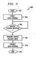
- the vehicle 100 may perform a method 300 of auto-guidance as depicted in FIG. 3 .
- the method begins at step 302.
- Auto-steering function is initiated.
- Auto-steering functions may be part of an auto-guidance system and/or an auto-guidance control routine.
- Steering controller 116 may receive control signals from master controller 104 and may, in turn, direct steering of the vehicle 100. In some embodiments, this may be accomplished by asserting control over steering shaft 112 and auto-steering the vehicle in so-called reaction type steering.
- the steering controller 116 may decouple the steering shaft 112 during auto-steering such that the steering shaft 112 (and, by extension, the steering wheel 114) does not turn in response to any steering and/or turning during auto-steering. This is commonly referred to as non-reaction type steering.
- step 306 it is determined if manual steering input has been detected.
- Manual steering input may occur when an operator turns steering wheel 114 during auto-steering. An operator may attempt to revert to manual steering in case of emergency, to avoid an obstacle, etc.
- the steering wheel 114 is turned, the steering shaft 112 may also be turned. Since the steering sensor 110 is mounted in such a way as to detect movement of the steering shaft 112 as described above, the steering sensor 110 would readily (e.g., immediately) detect the manual steering input.
- the steering sensor 110 may detect any movement of the steering shaft 110 which is greater than expected. That is, since the steering shaft 112 and steering wheel 114 turn in response to steering of the vehicle 100 in auto-steering and in the regular course of driving (e.g., minor course corrections, bumps, wheel movement, etc.), the steering sensor 110 may be adapted to detect a steering shaft 110 movement which exceeds a threshold indicating manual steering input has been entered.
- the steering shaft 112 is decoupled from steering unit 108 and/or steering controller 116 during auto-steering. Consequently, the threshold which indicates manual input detected by the steering sensor 110 may be lower than in reaction type steering. That is, there may some amount of inadvertent movement detected by the steering sensor 110 which is below an amount that indicates manual steering input.
- step 306 If manual steering input is detected in step 306, the method passes to step 308. If not, control is returned to step 306 to continue waiting for manual steering input.
- step 308 manual steering input information is transmitted.
- the steering sensor 110 may on its own or in connection with the steering unit 108 transmit detected manual steering input information to other components, such as master controller 104 and/or other controllers (e.g., steering controller 116).
- the steering sensor 110 may detect all movement of the steering shaft 112, but may only transmit signals indicative of manual steering input to master controller 104 when the amount of steering (e.g., the angle through which the steering shaft 112 has been turned) exceeds a predetermined threshold value.
- steering sensor 110 may transmit all steering angle changes to master controller 104 and/or steering controller 116 and these controllers may determine if manual steering input has been entered.
- step 310 auto-steering is disabled in response to detecting manual steering input.
- the master controller 104 and/or the steering controller 116 may disable auto-steering. This may be accomplished by ceasing sending auto-guidance and/or auto-steering control signals to the steering unit 108 and/or steering controller 116 or by suspending the signals such that if manual steering is relinquished, the auto-steering function may be brought back online quickly.
- This alternative may be useful in that an operator may manually steer the vehicle 100 via the steering wheel 114 around an obstacle, but may let go of the steering wheel 114 after passing the obstacle allowing the auto-guidance system to re-initiate auto-steering and course correction quickly to bring the vehicle 100 back into the originally intended path.
- the systems, apparatus, and methods described herein may be used in auto-guidance and auto-steering of agricultural vehicles such as tractors, harvesters, sprayers, combines, etc.
- the steering sensor 110 may pass steering angle, rate of angular change, and/or other appropriate information to the master controller and/or the steering controller 116. Such information may be used by the master controller and/or the steering controller 116 to enhance turning aggressiveness of the vehicle 100 during non-auto-steering operation. In this way, variable rate steering control may be employed. Variable rate steering control may allow the vehicle 100 to operate similarly to a standard automobile, which may increase handling and/or ease of use and deliver a more comfortable work environment.
Applications Claiming Priority (2)
| Application Number | Priority Date | Filing Date | Title |
|---|---|---|---|
| US11/899,899 US9051006B2 (en) | 2007-09-06 | 2007-09-06 | Method and apparatus for vehicle auto-guidance |
| PCT/US2008/007561 WO2009032030A1 (en) | 2007-09-06 | 2008-06-18 | Method and apparatus for vehicle auto-guidance |
Publications (2)
| Publication Number | Publication Date |
|---|---|
| EP2190718A1 EP2190718A1 (en) | 2010-06-02 |
| EP2190718B1 true EP2190718B1 (en) | 2014-08-13 |
Family
ID=39744760
Family Applications (1)
| Application Number | Title | Priority Date | Filing Date |
|---|---|---|---|
| EP08768555.8A Active EP2190718B1 (en) | 2007-09-06 | 2008-06-18 | Method and apparatus for vehicle auto-guidance |
Country Status (6)
| Country | Link |
|---|---|
| US (1) | US9051006B2 (zh) |
| EP (1) | EP2190718B1 (zh) |
| JP (1) | JP5496094B2 (zh) |
| AU (1) | AU2008295572B2 (zh) |
| CA (1) | CA2693380C (zh) |
| WO (1) | WO2009032030A1 (zh) |
Families Citing this family (9)
| Publication number | Priority date | Publication date | Assignee | Title |
|---|---|---|---|---|
| US8970363B2 (en) * | 2006-09-14 | 2015-03-03 | Crown Equipment Corporation | Wrist/arm/hand mounted device for remotely controlling a materials handling vehicle |
| ITTO20110795A1 (it) * | 2011-09-07 | 2013-03-08 | Cnh Italia Spa | Veicolo sterzabile |
| US9733643B2 (en) * | 2013-12-20 | 2017-08-15 | Agjunction Llc | Hydraulic interrupter safety system and method |
| JP6925780B2 (ja) * | 2016-02-03 | 2021-08-25 | 株式会社クボタ | 作業車 |
| JP6869808B2 (ja) * | 2017-05-26 | 2021-05-12 | 株式会社クボタ | 作業機の制御装置、作業機の制御方法及び作業機 |
| US10377409B2 (en) | 2017-08-17 | 2019-08-13 | Ford Global Technologies, Llc | Enhanced vehicle steering |
| MX2021009158A (es) | 2019-02-01 | 2021-09-10 | Crown Equip Corp | Vincular un dispositivo de control remoto a un vehiculo. |
| US11641121B2 (en) | 2019-02-01 | 2023-05-02 | Crown Equipment Corporation | On-board charging station for a remote control device |
| MX2023001754A (es) | 2020-08-11 | 2023-03-07 | Crown Equip Corp | Dispositivo de control remoto. |
Family Cites Families (22)
| Publication number | Priority date | Publication date | Assignee | Title |
|---|---|---|---|---|
| US2805585A (en) | 1956-03-12 | 1957-09-10 | Besserman Max | Push button electrically controlled steering adapter |
| US4170953A (en) | 1978-03-13 | 1979-10-16 | Signet Scientific Company | Detachable automatic pilot for wheel-steered boats |
| US4453485A (en) | 1981-09-08 | 1984-06-12 | Houghton Brown Patrick D | Device for remotely steering a boat |
| US5121799A (en) | 1988-07-29 | 1992-06-16 | Gar-Bar Corporation | Guiding agricultural vehicles |
| JP3211434B2 (ja) * | 1991-12-18 | 2001-09-25 | アイシン精機株式会社 | 車輛誘導制御装置 |
| JPH06336170A (ja) | 1993-05-27 | 1994-12-06 | Fuji Heavy Ind Ltd | 自動操舵装置の制御方法 |
| JP3627120B2 (ja) * | 1997-02-19 | 2005-03-09 | 光洋精工株式会社 | 車両用操舵装置 |
| US6198992B1 (en) * | 1997-10-10 | 2001-03-06 | Trimble Navigation Limited | Override for guidance control system |
| US6314348B1 (en) * | 1998-02-11 | 2001-11-06 | Trimble Navigation Limited | Correction control for guidance control system |
| JP3881775B2 (ja) | 1998-05-15 | 2007-02-14 | 本田技研工業株式会社 | 車両の自動操舵装置 |
| US6738695B1 (en) * | 2002-12-16 | 2004-05-18 | Caterpillar Inc | System and method for initializing autoguidance for a mobile machine |
| US7191061B2 (en) * | 2003-04-17 | 2007-03-13 | Battelle Energy Alliance, Llc | Auto-steering apparatus and method |
| JP4057954B2 (ja) | 2003-05-28 | 2008-03-05 | 本田技研工業株式会社 | 車両の自動操舵装置 |
| US7510038B2 (en) | 2003-06-11 | 2009-03-31 | Delphi Technologies, Inc. | Steering system with lane keeping integration |
| US6988583B2 (en) * | 2003-10-30 | 2006-01-24 | Deere & Company | Electrical steering system for manned or unmanned operation |
| US7610988B2 (en) | 2004-02-27 | 2009-11-03 | Sauer-Danfoss Aps | Hydraulic steering |
| CA2482252A1 (en) | 2004-09-21 | 2006-03-21 | Accutrak Systems Limited | Automatic steering system |
| JP2006117181A (ja) | 2004-10-25 | 2006-05-11 | Favess Co Ltd | 操舵制御装置 |
| DE102004057262A1 (de) * | 2004-11-26 | 2006-06-01 | Robert Bosch Gmbh | Verfahren und Vorrichtung zum Fahrerschutz bei fahrerunabhängiger Lenkmomentüberlagerung |
| US7574290B2 (en) * | 2004-11-30 | 2009-08-11 | Trimble Navigation Limited | Method and system for implementing automatic vehicle control with parameter-driven disengagement |
| TWI262874B (en) | 2005-09-12 | 2006-10-01 | De-Cheng Liau | Steering-assist system |
| US7363154B2 (en) * | 2005-10-12 | 2008-04-22 | Trimble Navigation Limited | Method and system for determining the path of a mobile machine |
-
2007
- 2007-09-06 US US11/899,899 patent/US9051006B2/en active Active
-
2008
- 2008-06-18 EP EP08768555.8A patent/EP2190718B1/en active Active
- 2008-06-18 JP JP2010523989A patent/JP5496094B2/ja not_active Expired - Fee Related
- 2008-06-18 WO PCT/US2008/007561 patent/WO2009032030A1/en active Application Filing
- 2008-06-18 CA CA2693380A patent/CA2693380C/en active Active
- 2008-06-18 AU AU2008295572A patent/AU2008295572B2/en active Active
Also Published As
| Publication number | Publication date |
|---|---|
| US20090069967A1 (en) | 2009-03-12 |
| US9051006B2 (en) | 2015-06-09 |
| CA2693380C (en) | 2013-11-12 |
| EP2190718A1 (en) | 2010-06-02 |
| CA2693380A1 (en) | 2009-03-12 |
| JP2010537892A (ja) | 2010-12-09 |
| AU2008295572A1 (en) | 2009-03-12 |
| AU2008295572B2 (en) | 2011-08-18 |
| JP5496094B2 (ja) | 2014-05-21 |
| WO2009032030A1 (en) | 2009-03-12 |
Similar Documents
| Publication | Publication Date | Title |
|---|---|---|
| EP2190718B1 (en) | Method and apparatus for vehicle auto-guidance | |
| AU2008275794B2 (en) | Vehicle auto-guidance memory | |
| EP3146823B1 (en) | Running system of work vehicle | |
| US9296423B2 (en) | Maximum trailer angle determination and control for a trailer backup assist system | |
| US11433722B2 (en) | Trailer and vehicle collision detection and response during autohitch maneuvering | |
| US20100332080A1 (en) | Method and apparatus for parking assistance | |
| US11180148B2 (en) | Detection and response to confined trailer in system-assisted hitch operation | |
| EP3468337A1 (en) | Autonomous agricultural system user interface interlock | |
| US11447178B2 (en) | Towing assist device | |
| US20210347410A1 (en) | Trailer gps location storage and recall for hitch assist operation | |
| EP3894302B1 (en) | A method for determining hydraulic failure in a hybrid steering system, a control device, a hybrid steering system and a vehicle | |
| CN111152839A (zh) | 从多辆已识别挂车中选择主挂车的自动挂接系统 | |
| US6738695B1 (en) | System and method for initializing autoguidance for a mobile machine | |
| US20210191387A1 (en) | System and method for assisted teleoperations of vehicles | |
| CN111267826A (zh) | 用于可接受挂接区中的车辆对准的人机界面 | |
| US11279187B2 (en) | Automatic alignment reattempt in automatic hitch operation | |
| CN113022700B (zh) | 一种车辆爆胎的安全控制方法及系统、车辆 | |
| WO2017184052A1 (en) | Method and system for facilitating steering of a vehicle by a driver of the vehicle during driving along a road | |
| JP7473385B2 (ja) | 作業車両 | |
| US20210094615A1 (en) | User-resolved activation sequence in assisted hitching operation |
Legal Events
| Date | Code | Title | Description |
|---|---|---|---|
| PUAI | Public reference made under article 153(3) epc to a published international application that has entered the european phase |
Free format text: ORIGINAL CODE: 0009012 |
|
| 17P | Request for examination filed |
Effective date: 20100406 |
|
| AK | Designated contracting states |
Kind code of ref document: A1 Designated state(s): AT BE BG CH CY CZ DE DK EE ES FI FR GB GR HR HU IE IS IT LI LT LU LV MC MT NL NO PL PT RO SE SI SK TR |
|
| AX | Request for extension of the european patent |
Extension state: AL BA MK RS |
|
| DAX | Request for extension of the european patent (deleted) | ||
| 17Q | First examination report despatched |
Effective date: 20111020 |
|
| GRAP | Despatch of communication of intention to grant a patent |
Free format text: ORIGINAL CODE: EPIDOSNIGR1 |
|
| INTG | Intention to grant announced |
Effective date: 20131211 |
|
| GRAP | Despatch of communication of intention to grant a patent |
Free format text: ORIGINAL CODE: EPIDOSNIGR1 |
|
| GRAS | Grant fee paid |
Free format text: ORIGINAL CODE: EPIDOSNIGR3 |
|
| GRAA | (expected) grant |
Free format text: ORIGINAL CODE: 0009210 |
|
| INTG | Intention to grant announced |
Effective date: 20140619 |
|
| AK | Designated contracting states |
Kind code of ref document: B1 Designated state(s): AT BE BG CH CY CZ DE DK EE ES FI FR GB GR HR HU IE IS IT LI LT LU LV MC MT NL NO PL PT RO SE SI SK TR |
|
| REG | Reference to a national code |
Ref country code: GB Ref legal event code: FG4D |
|
| REG | Reference to a national code |
Ref country code: CH Ref legal event code: EP Ref country code: AT Ref legal event code: REF Ref document number: 682025 Country of ref document: AT Kind code of ref document: T Effective date: 20140815 |
|
| REG | Reference to a national code |
Ref country code: IE Ref legal event code: FG4D |
|
| REG | Reference to a national code |
Ref country code: DE Ref legal event code: R096 Ref document number: 602008033846 Country of ref document: DE Effective date: 20140925 |
|
| REG | Reference to a national code |
Ref country code: NL Ref legal event code: VDEP Effective date: 20140813 |
|
| REG | Reference to a national code |
Ref country code: AT Ref legal event code: MK05 Ref document number: 682025 Country of ref document: AT Kind code of ref document: T Effective date: 20140813 |
|
| REG | Reference to a national code |
Ref country code: LT Ref legal event code: MG4D |
|
| PG25 | Lapsed in a contracting state [announced via postgrant information from national office to epo] |
Ref country code: FI Free format text: LAPSE BECAUSE OF FAILURE TO SUBMIT A TRANSLATION OF THE DESCRIPTION OR TO PAY THE FEE WITHIN THE PRESCRIBED TIME-LIMIT Effective date: 20140813 Ref country code: BG Free format text: LAPSE BECAUSE OF FAILURE TO SUBMIT A TRANSLATION OF THE DESCRIPTION OR TO PAY THE FEE WITHIN THE PRESCRIBED TIME-LIMIT Effective date: 20141113 Ref country code: LT Free format text: LAPSE BECAUSE OF FAILURE TO SUBMIT A TRANSLATION OF THE DESCRIPTION OR TO PAY THE FEE WITHIN THE PRESCRIBED TIME-LIMIT Effective date: 20140813 Ref country code: GR Free format text: LAPSE BECAUSE OF FAILURE TO SUBMIT A TRANSLATION OF THE DESCRIPTION OR TO PAY THE FEE WITHIN THE PRESCRIBED TIME-LIMIT Effective date: 20141114 Ref country code: SE Free format text: LAPSE BECAUSE OF FAILURE TO SUBMIT A TRANSLATION OF THE DESCRIPTION OR TO PAY THE FEE WITHIN THE PRESCRIBED TIME-LIMIT Effective date: 20140813 Ref country code: ES Free format text: LAPSE BECAUSE OF FAILURE TO SUBMIT A TRANSLATION OF THE DESCRIPTION OR TO PAY THE FEE WITHIN THE PRESCRIBED TIME-LIMIT Effective date: 20140813 Ref country code: NO Free format text: LAPSE BECAUSE OF FAILURE TO SUBMIT A TRANSLATION OF THE DESCRIPTION OR TO PAY THE FEE WITHIN THE PRESCRIBED TIME-LIMIT Effective date: 20141113 Ref country code: PT Free format text: LAPSE BECAUSE OF FAILURE TO SUBMIT A TRANSLATION OF THE DESCRIPTION OR TO PAY THE FEE WITHIN THE PRESCRIBED TIME-LIMIT Effective date: 20141215 |
|
| PG25 | Lapsed in a contracting state [announced via postgrant information from national office to epo] |
Ref country code: AT Free format text: LAPSE BECAUSE OF FAILURE TO SUBMIT A TRANSLATION OF THE DESCRIPTION OR TO PAY THE FEE WITHIN THE PRESCRIBED TIME-LIMIT Effective date: 20140813 Ref country code: LV Free format text: LAPSE BECAUSE OF FAILURE TO SUBMIT A TRANSLATION OF THE DESCRIPTION OR TO PAY THE FEE WITHIN THE PRESCRIBED TIME-LIMIT Effective date: 20140813 Ref country code: CY Free format text: LAPSE BECAUSE OF FAILURE TO SUBMIT A TRANSLATION OF THE DESCRIPTION OR TO PAY THE FEE WITHIN THE PRESCRIBED TIME-LIMIT Effective date: 20140813 Ref country code: IS Free format text: LAPSE BECAUSE OF FAILURE TO SUBMIT A TRANSLATION OF THE DESCRIPTION OR TO PAY THE FEE WITHIN THE PRESCRIBED TIME-LIMIT Effective date: 20141213 Ref country code: HR Free format text: LAPSE BECAUSE OF FAILURE TO SUBMIT A TRANSLATION OF THE DESCRIPTION OR TO PAY THE FEE WITHIN THE PRESCRIBED TIME-LIMIT Effective date: 20140813 |
|
| PG25 | Lapsed in a contracting state [announced via postgrant information from national office to epo] |
Ref country code: NL Free format text: LAPSE BECAUSE OF FAILURE TO SUBMIT A TRANSLATION OF THE DESCRIPTION OR TO PAY THE FEE WITHIN THE PRESCRIBED TIME-LIMIT Effective date: 20140813 |
|
| PG25 | Lapsed in a contracting state [announced via postgrant information from national office to epo] |
Ref country code: SK Free format text: LAPSE BECAUSE OF FAILURE TO SUBMIT A TRANSLATION OF THE DESCRIPTION OR TO PAY THE FEE WITHIN THE PRESCRIBED TIME-LIMIT Effective date: 20140813 Ref country code: DK Free format text: LAPSE BECAUSE OF FAILURE TO SUBMIT A TRANSLATION OF THE DESCRIPTION OR TO PAY THE FEE WITHIN THE PRESCRIBED TIME-LIMIT Effective date: 20140813 Ref country code: CZ Free format text: LAPSE BECAUSE OF FAILURE TO SUBMIT A TRANSLATION OF THE DESCRIPTION OR TO PAY THE FEE WITHIN THE PRESCRIBED TIME-LIMIT Effective date: 20140813 Ref country code: EE Free format text: LAPSE BECAUSE OF FAILURE TO SUBMIT A TRANSLATION OF THE DESCRIPTION OR TO PAY THE FEE WITHIN THE PRESCRIBED TIME-LIMIT Effective date: 20140813 Ref country code: IT Free format text: LAPSE BECAUSE OF FAILURE TO SUBMIT A TRANSLATION OF THE DESCRIPTION OR TO PAY THE FEE WITHIN THE PRESCRIBED TIME-LIMIT Effective date: 20140813 Ref country code: RO Free format text: LAPSE BECAUSE OF FAILURE TO SUBMIT A TRANSLATION OF THE DESCRIPTION OR TO PAY THE FEE WITHIN THE PRESCRIBED TIME-LIMIT Effective date: 20140813 |
|
| REG | Reference to a national code |
Ref country code: DE Ref legal event code: R097 Ref document number: 602008033846 Country of ref document: DE |
|
| REG | Reference to a national code |
Ref country code: FR Ref legal event code: PLFP Year of fee payment: 8 |
|
| PG25 | Lapsed in a contracting state [announced via postgrant information from national office to epo] |
Ref country code: PL Free format text: LAPSE BECAUSE OF FAILURE TO SUBMIT A TRANSLATION OF THE DESCRIPTION OR TO PAY THE FEE WITHIN THE PRESCRIBED TIME-LIMIT Effective date: 20140813 |
|
| PLBE | No opposition filed within time limit |
Free format text: ORIGINAL CODE: 0009261 |
|
| STAA | Information on the status of an ep patent application or granted ep patent |
Free format text: STATUS: NO OPPOSITION FILED WITHIN TIME LIMIT |
|
| 26N | No opposition filed |
Effective date: 20150515 |
|
| PG25 | Lapsed in a contracting state [announced via postgrant information from national office to epo] |
Ref country code: SI Free format text: LAPSE BECAUSE OF FAILURE TO SUBMIT A TRANSLATION OF THE DESCRIPTION OR TO PAY THE FEE WITHIN THE PRESCRIBED TIME-LIMIT Effective date: 20140813 |
|
| PG25 | Lapsed in a contracting state [announced via postgrant information from national office to epo] |
Ref country code: MC Free format text: LAPSE BECAUSE OF FAILURE TO SUBMIT A TRANSLATION OF THE DESCRIPTION OR TO PAY THE FEE WITHIN THE PRESCRIBED TIME-LIMIT Effective date: 20140813 |
|
| REG | Reference to a national code |
Ref country code: CH Ref legal event code: PL |
|
| PG25 | Lapsed in a contracting state [announced via postgrant information from national office to epo] |
Ref country code: LU Free format text: LAPSE BECAUSE OF FAILURE TO SUBMIT A TRANSLATION OF THE DESCRIPTION OR TO PAY THE FEE WITHIN THE PRESCRIBED TIME-LIMIT Effective date: 20150618 |
|
| REG | Reference to a national code |
Ref country code: IE Ref legal event code: MM4A |
|
| PG25 | Lapsed in a contracting state [announced via postgrant information from national office to epo] |
Ref country code: LI Free format text: LAPSE BECAUSE OF NON-PAYMENT OF DUE FEES Effective date: 20150630 Ref country code: CH Free format text: LAPSE BECAUSE OF NON-PAYMENT OF DUE FEES Effective date: 20150630 Ref country code: IE Free format text: LAPSE BECAUSE OF NON-PAYMENT OF DUE FEES Effective date: 20150618 |
|
| REG | Reference to a national code |
Ref country code: FR Ref legal event code: PLFP Year of fee payment: 9 |
|
| PG25 | Lapsed in a contracting state [announced via postgrant information from national office to epo] |
Ref country code: BE Free format text: LAPSE BECAUSE OF FAILURE TO SUBMIT A TRANSLATION OF THE DESCRIPTION OR TO PAY THE FEE WITHIN THE PRESCRIBED TIME-LIMIT Effective date: 20140813 |
|
| PG25 | Lapsed in a contracting state [announced via postgrant information from national office to epo] |
Ref country code: MT Free format text: LAPSE BECAUSE OF FAILURE TO SUBMIT A TRANSLATION OF THE DESCRIPTION OR TO PAY THE FEE WITHIN THE PRESCRIBED TIME-LIMIT Effective date: 20140813 |
|
| REG | Reference to a national code |
Ref country code: FR Ref legal event code: PLFP Year of fee payment: 10 |
|
| PG25 | Lapsed in a contracting state [announced via postgrant information from national office to epo] |
Ref country code: HU Free format text: LAPSE BECAUSE OF FAILURE TO SUBMIT A TRANSLATION OF THE DESCRIPTION OR TO PAY THE FEE WITHIN THE PRESCRIBED TIME-LIMIT; INVALID AB INITIO Effective date: 20080618 |
|
| PG25 | Lapsed in a contracting state [announced via postgrant information from national office to epo] |
Ref country code: TR Free format text: LAPSE BECAUSE OF FAILURE TO SUBMIT A TRANSLATION OF THE DESCRIPTION OR TO PAY THE FEE WITHIN THE PRESCRIBED TIME-LIMIT Effective date: 20140813 |
|
| REG | Reference to a national code |
Ref country code: FR Ref legal event code: PLFP Year of fee payment: 11 |
|
| PGFP | Annual fee paid to national office [announced via postgrant information from national office to epo] |
Ref country code: GB Payment date: 20220628 Year of fee payment: 15 |
|
| PGFP | Annual fee paid to national office [announced via postgrant information from national office to epo] |
Ref country code: FR Payment date: 20220627 Year of fee payment: 15 |
|
| PGFP | Annual fee paid to national office [announced via postgrant information from national office to epo] |
Ref country code: DE Payment date: 20220629 Year of fee payment: 15 |
|
| REG | Reference to a national code |
Ref country code: DE Ref legal event code: R119 Ref document number: 602008033846 Country of ref document: DE |
|
| GBPC | Gb: european patent ceased through non-payment of renewal fee |
Effective date: 20230618 |
|
| PG25 | Lapsed in a contracting state [announced via postgrant information from national office to epo] |
Ref country code: DE Free format text: LAPSE BECAUSE OF NON-PAYMENT OF DUE FEES Effective date: 20240103 Ref country code: GB Free format text: LAPSE BECAUSE OF NON-PAYMENT OF DUE FEES Effective date: 20230618 |