EP2190076B1 - Connecteur à fiches électrique - Google Patents
Connecteur à fiches électrique Download PDFInfo
- Publication number
- EP2190076B1 EP2190076B1 EP20090013338 EP09013338A EP2190076B1 EP 2190076 B1 EP2190076 B1 EP 2190076B1 EP 20090013338 EP20090013338 EP 20090013338 EP 09013338 A EP09013338 A EP 09013338A EP 2190076 B1 EP2190076 B1 EP 2190076B1
- Authority
- EP
- European Patent Office
- Prior art keywords
- contact
- plug
- plug connector
- female
- connector system
- Prior art date
- Legal status (The legal status is an assumption and is not a legal conclusion. Google has not performed a legal analysis and makes no representation as to the accuracy of the status listed.)
- Active
Links
Images
Classifications
-
- H—ELECTRICITY
- H01—ELECTRIC ELEMENTS
- H01R—ELECTRICALLY-CONDUCTIVE CONNECTIONS; STRUCTURAL ASSOCIATIONS OF A PLURALITY OF MUTUALLY-INSULATED ELECTRICAL CONNECTING ELEMENTS; COUPLING DEVICES; CURRENT COLLECTORS
- H01R13/00—Details of coupling devices of the kinds covered by groups H01R12/70 or H01R24/00 - H01R33/00
- H01R13/64—Means for preventing incorrect coupling
- H01R13/642—Means for preventing incorrect coupling by position or shape of contact members
-
- H—ELECTRICITY
- H01—ELECTRIC ELEMENTS
- H01R—ELECTRICALLY-CONDUCTIVE CONNECTIONS; STRUCTURAL ASSOCIATIONS OF A PLURALITY OF MUTUALLY-INSULATED ELECTRICAL CONNECTING ELEMENTS; COUPLING DEVICES; CURRENT COLLECTORS
- H01R13/00—Details of coupling devices of the kinds covered by groups H01R12/70 or H01R24/00 - H01R33/00
- H01R13/64—Means for preventing incorrect coupling
- H01R13/645—Means for preventing incorrect coupling by exchangeable elements on case or base
-
- H—ELECTRICITY
- H01—ELECTRIC ELEMENTS
- H01R—ELECTRICALLY-CONDUCTIVE CONNECTIONS; STRUCTURAL ASSOCIATIONS OF A PLURALITY OF MUTUALLY-INSULATED ELECTRICAL CONNECTING ELEMENTS; COUPLING DEVICES; CURRENT COLLECTORS
- H01R31/00—Coupling parts supported only by co-operation with counterpart
-
- H—ELECTRICITY
- H01—ELECTRIC ELEMENTS
- H01R—ELECTRICALLY-CONDUCTIVE CONNECTIONS; STRUCTURAL ASSOCIATIONS OF A PLURALITY OF MUTUALLY-INSULATED ELECTRICAL CONNECTING ELEMENTS; COUPLING DEVICES; CURRENT COLLECTORS
- H01R13/00—Details of coupling devices of the kinds covered by groups H01R12/70 or H01R24/00 - H01R33/00
- H01R13/40—Securing contact members in or to a base or case; Insulating of contact members
- H01R13/405—Securing in non-demountable manner, e.g. moulding, riveting
-
- H—ELECTRICITY
- H01—ELECTRIC ELEMENTS
- H01R—ELECTRICALLY-CONDUCTIVE CONNECTIONS; STRUCTURAL ASSOCIATIONS OF A PLURALITY OF MUTUALLY-INSULATED ELECTRICAL CONNECTING ELEMENTS; COUPLING DEVICES; CURRENT COLLECTORS
- H01R13/00—Details of coupling devices of the kinds covered by groups H01R12/70 or H01R24/00 - H01R33/00
- H01R13/46—Bases; Cases
- H01R13/465—Identification means, e.g. labels, tags, markings
-
- H—ELECTRICITY
- H01—ELECTRIC ELEMENTS
- H01R—ELECTRICALLY-CONDUCTIVE CONNECTIONS; STRUCTURAL ASSOCIATIONS OF A PLURALITY OF MUTUALLY-INSULATED ELECTRICAL CONNECTING ELEMENTS; COUPLING DEVICES; CURRENT COLLECTORS
- H01R13/00—Details of coupling devices of the kinds covered by groups H01R12/70 or H01R24/00 - H01R33/00
- H01R13/46—Bases; Cases
- H01R13/502—Bases; Cases composed of different pieces
-
- H—ELECTRICITY
- H01—ELECTRIC ELEMENTS
- H01R—ELECTRICALLY-CONDUCTIVE CONNECTIONS; STRUCTURAL ASSOCIATIONS OF A PLURALITY OF MUTUALLY-INSULATED ELECTRICAL CONNECTING ELEMENTS; COUPLING DEVICES; CURRENT COLLECTORS
- H01R13/00—Details of coupling devices of the kinds covered by groups H01R12/70 or H01R24/00 - H01R33/00
- H01R13/46—Bases; Cases
- H01R13/52—Dustproof, splashproof, drip-proof, waterproof, or flameproof cases
- H01R13/5219—Sealing means between coupling parts, e.g. interfacial seal
-
- H—ELECTRICITY
- H01—ELECTRIC ELEMENTS
- H01R—ELECTRICALLY-CONDUCTIVE CONNECTIONS; STRUCTURAL ASSOCIATIONS OF A PLURALITY OF MUTUALLY-INSULATED ELECTRICAL CONNECTING ELEMENTS; COUPLING DEVICES; CURRENT COLLECTORS
- H01R13/00—Details of coupling devices of the kinds covered by groups H01R12/70 or H01R24/00 - H01R33/00
- H01R13/62—Means for facilitating engagement or disengagement of coupling parts or for holding them in engagement
- H01R13/627—Snap or like fastening
- H01R13/6275—Latching arms not integral with the housing
-
- H—ELECTRICITY
- H01—ELECTRIC ELEMENTS
- H01R—ELECTRICALLY-CONDUCTIVE CONNECTIONS; STRUCTURAL ASSOCIATIONS OF A PLURALITY OF MUTUALLY-INSULATED ELECTRICAL CONNECTING ELEMENTS; COUPLING DEVICES; CURRENT COLLECTORS
- H01R13/00—Details of coupling devices of the kinds covered by groups H01R12/70 or H01R24/00 - H01R33/00
- H01R13/66—Structural association with built-in electrical component
- H01R13/6608—Structural association with built-in electrical component with built-in single component
- H01R13/6641—Structural association with built-in electrical component with built-in single component with diode
Definitions
- the invention relates to an electrical connector, in particular a photovoltaic connector.
- the invention therefore relates to a connector according to the preamble of claim 1.
- These are generally single-pole connectors, with which the electricity of solar modules can be dissipated and forwarded, or with the help of solar modules can be connected together.
- a connector for photovoltaic connection cables known with a plug having a handle body, which oriented in the insertion direction, at least one latching means and a contact carrier and with a socket whose handle body forms a contact carrier receptacle and a locking means corresponding counter-locking means, which together with the locking means secures the plug in the socket in the plugged state, wherein the contact carrier and the contact carrier receptacle form mutually corresponding positioning means which allow insertion of the plug into the socket only in the counter-locking means facing locking means.
- the US 6,582,249 B1 shows a junction box 2, on which a contact carrier 6 is arranged and arranged externally.
- the US 7,387,537 B1 discloses a connector system having the features of the first part of claim 1.
- plugs or plugs and sockets therefore have positioning means to ensure during assembly that during insertion of the plug exclusively with oriented in the direction of the locking tunnel locking tongues can be inserted into the beech.
- an electrical connector is needed so that a space-saving design does not hinder the installation of bricks.
- a flat electrical connector is necessary, but which must have sufficient Isolierstoffêt.
- rubber materials are preferably used for the seal, which in addition withstands exposure to UV radiation and other environmental stresses.
- the object of the present invention is therefore to provide an electrical connector for photovoltaic applications, in particular for photovoltaic roof tiles.
- Another object of the present invention is to provide a connector system such that a part of the connector, preferably the junction box is already electrically connectable to the generator, that is to say the photovoltaic roof tile and the photovoltaic bricks are to bring into electrical contact with each other.
- the connector system therefore requires a technical solution that makes it possible to interconnect roof tiles together. Since in each case a roof tile must come into electrical contact with their adjacent roof tiles, it is therefore necessary, depending on the installation and interconnection, to bring each three bricks together electrically pluggable connection.
- Object of the present invention is therefore to make an electrical connector system such that not only one tile with the next is connectable, but a tile can be brought by means of the same electrical connector with two other tiles in electrical contact.
- junction box on the photovoltaic brick must be the shape that it must be electrically contacted with the contacts of the generator unit of the brick, if possible in a simpler and cheaper, ie in such a way in that this is possible by machine welding.
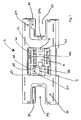
- the in Fig. 1 shown part of the photovoltaic connector 1 shows the junction box 2 or more generally a contact body 33, designed as a junction box.
- the junction box 2 is a substantially flat junction box with a height of about 5 mm to 10 mm, suitable for receiving two female connectors 6, as in Fig. 2 to Fig. 6 are shown.
- the length and width of the junction box 2 is many times greater than the height of about 3 to 10 times.
- junction box 2 with its structural and functional features will first be described in more detail.
- the junction box 2 has a junction box top 20 and a junction box bottom 27.
- the junction box 2 is a substantially flat, almost parallelepipedmaschinegroper 33, which has a molded in the junction box bottom recess 21 in its central part.
- the recess 21 is formed as a step-shaped recess, wherein two diametrically opposite step portions are formed as steps with grooves 22.
- the grooves 22 extend through the contact body 33 and thus form openings which are formed to the opposite junction box top.
- the grooves 22 are formed as elongated slots in the contact body 33 in the region of the recess 21.
- the grooves 22 serve to receive terminal ends of a metallic contact holding element 4, which will be described in more detail in a later section.
- the contact body 33 has in the region of the recess 21 further via fastening means 23, preferably lateral fastening means 23, for the contact elements 4.
- the fastening means 23 are integrally formed with the contact body 33 in an advantageous embodiment of the invention.
- At the attachment means 23 are for each contact holding element 4 fastening means-side locking means 24.
- the locking means 24 further comprise a stop surface 25 for the contact elements 4, and a ramp 26 to detent springs 43 of the contact holding elements 4 thereto to move sliding and deflecting during assembly of the contact elements 4 in the contact body. 2
- the insertion side openings 28a, 28b lie in the region of the plug-side recesses 29, which can accommodate parts of the contour of the female connector 6.
- the plug-side recesses 29 form a total of apertures in the contact body 33 of the junction box 2.
- the contact body 33 in the region of the recess 29 codes 78, optionally in the junction box top 20 and / or in the junction box bottom 27, and lateral guide means 30, preferably junction box upper side and junction box underside guide means 30, for inserting the female connector 6 in the junction box. 2
- the junction box 2 further has contact carrier-side locking means 31, preferably via a plurality of such locking means for fixing and locking with counter-locking means of the female connector 6, preferably with latching hooks 73 of the female connector. 6
- the contact carrier-side locking means 31 are preferably arranged in apertures 32 of the contact carrier 2 in the region of the plug-side recesses 29, that they can come into operative connection with the female connector or the latching means 72 during insertion.
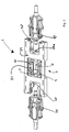
- two contact holding elements 4 are introduced into the recess 21 in the present invention in the connector 21 in the present embodiment.
- the contact holding elements 4 can be brought into electrical contact with one another by means of an electrical connection element 5.
- the connecting element 5 may be a power converter element, such as a diode. In this way it can be ensured that when contacting and connecting a photovoltaic brick with two adjacent photovoltaic bricks of the current and thus the energy transport takes place only in one direction.
- the contact elements 4 are metallic contact elements for connection to the contacts, preferably the pin contacts 3 of the connector.
- the task of the contact holding elements 4 is, on the one hand, an electrical connection with the contacts on the photovoltaic bricks, that is to say the contact pads of the bricks, and on the other hand secure the two pin contacts 3 securely in the contact body 33. Therefore, the contact element 4 has holding portions 40 and fixing portions 41.
- the holding portion 40 serves to hold the contact elements 3, while the fixing portion 41 of the attachment of the contact holding member 4 on the contact carrier 33 is used.
- connection ends 42 for electrically connecting the contact holding elements 4 and thus the contact elements 3 with the generator unit of the photovoltaic brick or with the contact fields of the photovoltaic bricks. These are preferably electrically welded through the contact, thus through the grooves 22, which are formed as openings in the contact carrier 33, by means of lasers to the contact pads of the photovoltaic bricks.
- the holding portions 40 further have locking springs 43 which are frictionally supported on the locking means 24 and the stop surface 25 of the locking means 24 on the contact body 33 as soon as the contact holding elements 4 are correctly inserted into the contact carrier 33.
- the contact elements 3 do not protrude from the insertion openings 28a, 28b, but are located completely within the latter, so that contact protection against unintentional contact with live parts is ensured.
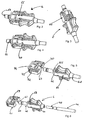
- the female connector 6 is composed of a contact body 60 and a plug-in adapter 61, preferably a coded plug-in adapter 61, which is rotatable and insertable on the contact body 60 can be fixed.
- the contact body 60 is preferably made of an elastic plastic. In a preferred embodiment, the contact body 60 is made of UV resistant rubber.
- the plug-in adapter 61 is made of a, compared to the elastic plastic, firmer, almost massive plastic. This serves to ensure that the stability of the connector and thus the holding function is generated by the less elastic plug adapter 61, while the sealing function, ie the sealing properties against environmental and moisture influences are generated by the elastic rubber contact body 60.
- the contact body 60 has a cylindrical socket contact holder 62, in which a cylindrical socket contact 75 is introduced.
- the socket contact 75 is connectable to a line 76.
- the diameter of the line 76 is to be tuned to the opening of the cable grommet 68, which is located on the contact body 60.
- the cable grommet 68 encloses sealingly the cable 76.
- an adapter connector portion 65 suitable for connection to the plug adapter 61st
- the adapter connector portion 65 comprises coding means 66 in an advantageous manner as laterally mounted web-like locking elements for engagement in the plug adapter 61.
- Codierelments 79 which is advantageously designed as a step on the plug adapter 61, it is ensured that only the respective correct plug adapter 61 with the respective correct insertion opening 28a, 28b is connected.
- a color coding of one of the two counterparts that is to say the plug-in adapter 61 or the contact body 60
- the plug-in adapter 61 or the contact body 60 can also be attached.
- To assemble the contact body 60 it is guided with the cylindrical socket contact holder 62 through the bushing contact holder-side bushing 74 until the adapter connection section 65 rests against the plug adapter 61 and engagement means 70 of the plug adapter 61 are fixed by turning the plug adapter 61 with an engagement groove 69 of the contact body 60 in the region of the adapter connection section 65 can be.
- the plug-in adapter 61 can only be brought into the desired rotational / locking position when the counter-coding means 67 with the coding means 66 of the contact body 60 match one another.
- the plug-in adapter 61 may advantageously have a cylindrical pressing portion 80, which is dimensioned such that the cylindrical socket contact holder 62 undergoes a pressure in the mounted state by this.
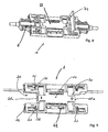
- the female connector 6 has at its plug adapter 61 via laterally mounted locking means 72 with the latching means 72 mounted latching hooks 73 for fixing with the aforementioned contact carrier-side locking means 31 in the openings 32nd
- the locking means 72 can engage with the contact carrier side locking means 31. This is done at the end of the insertion movement so that it is visually recognizable that the connector pair has been inserted correctly.
- the sealing means 64 are preferably formed as a radial annular sealing elements, integral with the socket contact holder 62. These are used for the radial sealing of the plug connection in the region of the insertion openings 28a, 28b of the contact body 33 of the junction box 2.
- release tool 77 solve its plug position to disconnect it from the connector.
- the release tool 77 can engage in the openings 32 of the contact body 33 such that the contact carrier side locking means 31 are rebounded and thereby release the locking means 72 of the plug adapter 61.
Claims (11)
- Système de connecteur à fiches électrique comprenant deux connecteurs à fiches femelles (6) et une boîte de raccordement (2) qui présente un support de contacts essentiellement plat (33), le support de contacts (33) disposant de deux ouvertures d'enfichage (28a, 28b) ayant chacune un élément de contact (3) monté dans les ouvertures d'enfichage (28a, 28b), pour l'engagement par enfichage avec un connecteur à fiches femelle respectif (6), les deux ouvertures d'enfichage (28a, 28b) étant réalisées au niveau de deux évidements opposés (29) du support de contacts (33), caractérisé en ce que les deux connecteurs à fiches femelles (6) sont réalisés en deux parties, à savoir sont constitués d'un corps de contact (60) et d'un adaptateur enfichable (61) pouvant être connecté au corps de contact (60), celui-ci disposant d'un élément de codage (79) qui garantit que seulement l'adaptateur enfichable correct respectif (61) est connecté à l'ouverture d'enfichage (28a, 28b) correcte respective.
- Système de connecteur à fiches selon la revendication 1, caractérisé en ce que le support de contact (33) dispose d'un évidement (21) dans la région entre les ouvertures d'enfichage (28a, 28b) et deux éléments de retenue de contact (4) électriquement conducteurs sont disposés dans l'évidement (21) et ceux-ci sont connectés électriquement à un élément de contact respectif (3).
- Système de connecteur à fiches selon la revendication 2, caractérisé en ce que chaque élément de retenue de contact (4) dispose d'une portion de retenue (40) pour retenir l'élément de contact (3) et d'une portion de fixation (41) avec laquelle chaque élément de retenue de contact (4) est encliqueté au support de contact (33).
- Système de connecteur à fiches selon l'une quelconque des revendications précédentes, caractérisé en ce que des moyens de guidage (30) pour le guidage d'une fiche femelle (6) lors de l'enfichage dans la boîte de raccordement (2) sont montés au niveau des évidements (29) côté enfichage.
- Système de connecteur à fiches selon l'une quelconque des revendications précédentes, caractérisé en ce qu'au moins un moyen d'encliquetage (31) du côté du support de contact est disposé au niveau du support de contact (33) dans des orifices (32) du côté du support de contact pour l'engagement dans des moyens d'encliquetage (72) d'un connecteur à fiches femelle (6).
- Système de connecteur à fiches selon l'une quelconque des revendications 2 à 5, caractérisé en ce que chaque élément de retenue de contact (4) dispose d'au moins une extrémité de raccordement (42) pour la connexion électrique à une région de raccordement d'une tuile de toit photovoltaïque, de préférence pour le contact direct immédiat avec un contact d'une telle tuile de toit.
- Système de connecteur à fiches selon la revendication 6, caractérisé en ce que les extrémités de raccordement (42) sont disposées dans la région d'ouvertures, de préférence de rainures (22), qui sont réalisées sous forme d'ouvertures traversantes dans le support de contact (33).
- Système de connecteur à fiches selon la revendication 7, caractérisé en ce que le corps de contact (60) est formé d'un matériau en plastique élastique, de préférence de caoutchouc, tandis que l'adaptateur enfichable (61) est constitué d'un plastique de plus grande solidité que du caoutchouc.
- Système de connecteur à fiches selon la revendication 8, caractérisé en ce que l'adaptateur enfichable (61) est réalisé sous forme d'adaptateur enfichable et rotatif (61) et peut être fixé au moyen d'un mouvement d'enfichage et de rotation au corps de contact (60).
- Système de connecteur à fiches selon la revendication 9, caractérisé en ce que le corps de contact (60) comprenant un dispositif de retenue de contact femelle cylindrique (62) avec un contact femelle (75) se trouvant dans le dispositif de retenue de contact femelle, au niveau de l'extrémité côté enfichage duquel se trouvent des moyens d'étanchéité (64) pour réaliser l'étanchéité du connecteur à fiches.
- Système de connecteur à fiches selon l'une quelconque des revendications 9 ou 10, caractérisé en ce que l'adaptateur enfichable (61) dispose d'un passage de retenue de contact femelle (74) qui est réalisé pour le passage du dispositif de retenue de contact femelle cylindrique (62), ainsi que de moyens d'encliquetage disposés latéralement (72) pour l'enfichage encliquetable avec les moyens d'encliquetage (31), du côté du support de contact, de la boîte de raccordement (2).
Applications Claiming Priority (1)
| Application Number | Priority Date | Filing Date | Title |
|---|---|---|---|
| DE200810059000 DE102008059000B4 (de) | 2008-11-25 | 2008-11-25 | Elektrisches Steckverbindersystem |
Publications (2)
| Publication Number | Publication Date |
|---|---|
| EP2190076A1 EP2190076A1 (fr) | 2010-05-26 |
| EP2190076B1 true EP2190076B1 (fr) | 2015-04-08 |
Family
ID=41667798
Family Applications (1)
| Application Number | Title | Priority Date | Filing Date |
|---|---|---|---|
| EP20090013338 Active EP2190076B1 (fr) | 2008-11-25 | 2009-10-22 | Connecteur à fiches électrique |
Country Status (2)
| Country | Link |
|---|---|
| EP (1) | EP2190076B1 (fr) |
| DE (1) | DE102008059000B4 (fr) |
Families Citing this family (2)
| Publication number | Priority date | Publication date | Assignee | Title |
|---|---|---|---|---|
| DE102017000102A1 (de) * | 2017-01-09 | 2018-07-12 | Osram Gmbh | Stecker, buchse, verbindungsstecker, leuchte und set |
| CN111200207B (zh) * | 2020-02-21 | 2021-08-13 | 朝禾天禄科技(北京)有限公司 | 数据接口保护系统的保护方法、保护装置与存储介质 |
Family Cites Families (6)
| Publication number | Priority date | Publication date | Assignee | Title |
|---|---|---|---|---|
| DE60039019D1 (de) | 1999-11-17 | 2008-07-10 | Tyco Electronics Amp Gmbh | Vorrichtung zur Verbindung von Leiterfolien, insbesondere von einem Solarmodul |
| JP2006147189A (ja) * | 2004-11-16 | 2006-06-08 | Sumitomo Wiring Syst Ltd | 太陽電池モジュール用コネクタ |
| EP2005486B1 (fr) * | 2006-04-13 | 2010-10-20 | Weidmüller Interface GmbH & Co. KG | Dispositif de connexion électrique pour conducteurs plats |
| US7387537B1 (en) * | 2007-01-03 | 2008-06-17 | Tyco Electronics Corporation | Connector system for solar cell roofing tiles |
| DE102007023210B3 (de) * | 2007-05-18 | 2008-09-18 | Anton Gensler Gmbh | Elekrische Anschlusseinrichtung für photovaltaische Module |
| DE202007017521U1 (de) | 2007-12-15 | 2008-08-21 | Lumberg Connect Gmbh | Steckverbinder für Photovoltaikanschlusskabel |
-
2008
- 2008-11-25 DE DE200810059000 patent/DE102008059000B4/de not_active Expired - Fee Related
-
2009
- 2009-10-22 EP EP20090013338 patent/EP2190076B1/fr active Active
Also Published As
| Publication number | Publication date |
|---|---|
| DE102008059000A1 (de) | 2010-06-02 |
| DE102008059000B4 (de) | 2010-10-21 |
| EP2190076A1 (fr) | 2010-05-26 |
Similar Documents
| Publication | Publication Date | Title |
|---|---|---|
| DE102013213336B4 (de) | Elektrischer steckverbinder, ladedose und steckverbindersystem für ein elektro- oder hybridfahrzeug | |
| EP2022142B1 (fr) | Connecteur enfichable | |
| EP2777096B2 (fr) | Unité de connexion à fiches multipolaire pour systèmes électriques triphasés | |
| EP2962366B1 (fr) | Connecteur électrique industriel | |
| WO2010046293A1 (fr) | Connexion par enfichage comportant un élément mâle et un élément femelle, et boîtiers d'adaptateur destinés à recevoir ladite connexion par enfichage | |
| EP2452220A1 (fr) | Dispositif connecteur pour câble optique | |
| EP3613110B1 (fr) | Assemblage d'une pièce de connecteur à fiches avec insert de contact et élément de mise à la terre | |
| DE1615001B2 (de) | Elektrische steckvorrichtung | |
| EP2034566A2 (fr) | Connexion à fiche photovoltaïque | |
| EP1901402A1 (fr) | Connecteur solaire doté de moyens d'encliquetage améliorés | |
| EP2118969B1 (fr) | Système de connecteurs | |
| DE102007055040B4 (de) | Kontaktelement und Verfahren zur Herstellung eines Kontaktelementes | |
| DE102005012441B4 (de) | Elektrischer Steckverbinder sowie Verfahren zur Herstellung eines elektrischen Steckverbinders | |
| CH697606B1 (de) | Steckbare Kabelkupplung. | |
| EP2606538A1 (fr) | Connecteur | |
| EP1936755B1 (fr) | Connecteur comportant une prise et une douille avec un support de contacts et une collerette de protection | |
| EP2190076B1 (fr) | Connecteur à fiches électrique | |
| DE102016124496B3 (de) | Universaladapter für einen Steckverbinderkopf sowie Steckverbinderteil mit einem derartigen Steckverbinderkopf | |
| EP3522301B1 (fr) | Dispositif de raccordement et agencement d'alimentation en énergie | |
| DE202008005493U1 (de) | Steckverbindung für die Außenanwendung, insbesondere für Solarpanels | |
| EP1756919B1 (fr) | Adaptateur de branchement electrique et prise de courant | |
| DE102019210235B4 (de) | Direktsteckverbinder | |
| EP3399599B1 (fr) | Connecteur enfichable, fiche et système de connecteur enfichable | |
| DE19525801C2 (de) | Vorrichtung zum elektrisch leitenden Verbinden von zwei elektrischen Leitungen | |
| DE10346367B4 (de) | Freidrehbarer HF-Winkelsteckverbinder |
Legal Events
| Date | Code | Title | Description |
|---|---|---|---|
| PUAI | Public reference made under article 153(3) epc to a published international application that has entered the european phase |
Free format text: ORIGINAL CODE: 0009012 |
|
| AK | Designated contracting states |
Kind code of ref document: A1 Designated state(s): AT BE BG CH CY CZ DE DK EE ES FI FR GB GR HR HU IE IS IT LI LT LU LV MC MK MT NL NO PL PT RO SE SI SK SM TR |
|
| AX | Request for extension of the european patent |
Extension state: AL BA RS |
|
| 17P | Request for examination filed |
Effective date: 20101126 |
|
| 17Q | First examination report despatched |
Effective date: 20110117 |
|
| REG | Reference to a national code |
Ref country code: DE Ref legal event code: R079 Ref document number: 502009010866 Country of ref document: DE Free format text: PREVIOUS MAIN CLASS: H01R0013642000 Ipc: H01R0013405000 |
|
| RIC1 | Information provided on ipc code assigned before grant |
Ipc: H01R 13/52 20060101ALI20141007BHEP Ipc: H01R 13/627 20060101ALI20141007BHEP Ipc: H01R 13/642 20060101ALI20141007BHEP Ipc: H01R 31/00 20060101ALI20141007BHEP Ipc: H01R 13/502 20060101ALI20141007BHEP Ipc: H01R 13/66 20060101ALI20141007BHEP Ipc: H01R 13/405 20060101AFI20141007BHEP Ipc: H01R 13/46 20060101ALI20141007BHEP Ipc: H01R 13/645 20060101ALI20141007BHEP |
|
| GRAP | Despatch of communication of intention to grant a patent |
Free format text: ORIGINAL CODE: EPIDOSNIGR1 |
|
| INTG | Intention to grant announced |
Effective date: 20141202 |
|
| GRAS | Grant fee paid |
Free format text: ORIGINAL CODE: EPIDOSNIGR3 |
|
| GRAA | (expected) grant |
Free format text: ORIGINAL CODE: 0009210 |
|
| AK | Designated contracting states |
Kind code of ref document: B1 Designated state(s): AT BE BG CH CY CZ DE DK EE ES FI FR GB GR HR HU IE IS IT LI LT LU LV MC MK MT NL NO PL PT RO SE SI SK SM TR |
|
| AX | Request for extension of the european patent |
Extension state: AL BA RS |
|
| REG | Reference to a national code |
Ref country code: GB Ref legal event code: FG4D Free format text: NOT ENGLISH |
|
| REG | Reference to a national code |
Ref country code: CH Ref legal event code: EP |
|
| REG | Reference to a national code |
Ref country code: IE Ref legal event code: FG4D Free format text: LANGUAGE OF EP DOCUMENT: GERMAN |
|
| REG | Reference to a national code |
Ref country code: AT Ref legal event code: REF Ref document number: 721173 Country of ref document: AT Kind code of ref document: T Effective date: 20150515 |
|
| REG | Reference to a national code |
Ref country code: DE Ref legal event code: R096 Ref document number: 502009010866 Country of ref document: DE Effective date: 20150521 |
|
| REG | Reference to a national code |
Ref country code: NL Ref legal event code: VDEP Effective date: 20150408 |
|
| REG | Reference to a national code |
Ref country code: LT Ref legal event code: MG4D |
|
| PG25 | Lapsed in a contracting state [announced via postgrant information from national office to epo] |
Ref country code: NL Free format text: LAPSE BECAUSE OF FAILURE TO SUBMIT A TRANSLATION OF THE DESCRIPTION OR TO PAY THE FEE WITHIN THE PRESCRIBED TIME-LIMIT Effective date: 20150408 |
|
| REG | Reference to a national code |
Ref country code: FR Ref legal event code: PLFP Year of fee payment: 7 |
|
| PG25 | Lapsed in a contracting state [announced via postgrant information from national office to epo] |
Ref country code: LT Free format text: LAPSE BECAUSE OF FAILURE TO SUBMIT A TRANSLATION OF THE DESCRIPTION OR TO PAY THE FEE WITHIN THE PRESCRIBED TIME-LIMIT Effective date: 20150408 Ref country code: HR Free format text: LAPSE BECAUSE OF FAILURE TO SUBMIT A TRANSLATION OF THE DESCRIPTION OR TO PAY THE FEE WITHIN THE PRESCRIBED TIME-LIMIT Effective date: 20150408 Ref country code: ES Free format text: LAPSE BECAUSE OF FAILURE TO SUBMIT A TRANSLATION OF THE DESCRIPTION OR TO PAY THE FEE WITHIN THE PRESCRIBED TIME-LIMIT Effective date: 20150408 Ref country code: PT Free format text: LAPSE BECAUSE OF FAILURE TO SUBMIT A TRANSLATION OF THE DESCRIPTION OR TO PAY THE FEE WITHIN THE PRESCRIBED TIME-LIMIT Effective date: 20150810 Ref country code: FI Free format text: LAPSE BECAUSE OF FAILURE TO SUBMIT A TRANSLATION OF THE DESCRIPTION OR TO PAY THE FEE WITHIN THE PRESCRIBED TIME-LIMIT Effective date: 20150408 Ref country code: NO Free format text: LAPSE BECAUSE OF FAILURE TO SUBMIT A TRANSLATION OF THE DESCRIPTION OR TO PAY THE FEE WITHIN THE PRESCRIBED TIME-LIMIT Effective date: 20150708 |
|
| PG25 | Lapsed in a contracting state [announced via postgrant information from national office to epo] |
Ref country code: IS Free format text: LAPSE BECAUSE OF FAILURE TO SUBMIT A TRANSLATION OF THE DESCRIPTION OR TO PAY THE FEE WITHIN THE PRESCRIBED TIME-LIMIT Effective date: 20150808 Ref country code: GR Free format text: LAPSE BECAUSE OF FAILURE TO SUBMIT A TRANSLATION OF THE DESCRIPTION OR TO PAY THE FEE WITHIN THE PRESCRIBED TIME-LIMIT Effective date: 20150709 Ref country code: LV Free format text: LAPSE BECAUSE OF FAILURE TO SUBMIT A TRANSLATION OF THE DESCRIPTION OR TO PAY THE FEE WITHIN THE PRESCRIBED TIME-LIMIT Effective date: 20150408 |
|
| REG | Reference to a national code |
Ref country code: DE Ref legal event code: R097 Ref document number: 502009010866 Country of ref document: DE |
|
| PG25 | Lapsed in a contracting state [announced via postgrant information from national office to epo] |
Ref country code: EE Free format text: LAPSE BECAUSE OF FAILURE TO SUBMIT A TRANSLATION OF THE DESCRIPTION OR TO PAY THE FEE WITHIN THE PRESCRIBED TIME-LIMIT Effective date: 20150408 Ref country code: DK Free format text: LAPSE BECAUSE OF FAILURE TO SUBMIT A TRANSLATION OF THE DESCRIPTION OR TO PAY THE FEE WITHIN THE PRESCRIBED TIME-LIMIT Effective date: 20150408 |
|
| PLBE | No opposition filed within time limit |
Free format text: ORIGINAL CODE: 0009261 |
|
| STAA | Information on the status of an ep patent application or granted ep patent |
Free format text: STATUS: NO OPPOSITION FILED WITHIN TIME LIMIT |
|
| PG25 | Lapsed in a contracting state [announced via postgrant information from national office to epo] |
Ref country code: PL Free format text: LAPSE BECAUSE OF FAILURE TO SUBMIT A TRANSLATION OF THE DESCRIPTION OR TO PAY THE FEE WITHIN THE PRESCRIBED TIME-LIMIT Effective date: 20150408 Ref country code: SK Free format text: LAPSE BECAUSE OF FAILURE TO SUBMIT A TRANSLATION OF THE DESCRIPTION OR TO PAY THE FEE WITHIN THE PRESCRIBED TIME-LIMIT Effective date: 20150408 Ref country code: CZ Free format text: LAPSE BECAUSE OF FAILURE TO SUBMIT A TRANSLATION OF THE DESCRIPTION OR TO PAY THE FEE WITHIN THE PRESCRIBED TIME-LIMIT Effective date: 20150408 Ref country code: RO Free format text: LAPSE BECAUSE OF NON-PAYMENT OF DUE FEES Effective date: 20150408 |
|
| 26N | No opposition filed |
Effective date: 20160111 |
|
| PG25 | Lapsed in a contracting state [announced via postgrant information from national office to epo] |
Ref country code: IT Free format text: LAPSE BECAUSE OF FAILURE TO SUBMIT A TRANSLATION OF THE DESCRIPTION OR TO PAY THE FEE WITHIN THE PRESCRIBED TIME-LIMIT Effective date: 20150408 |
|
| PG25 | Lapsed in a contracting state [announced via postgrant information from national office to epo] |
Ref country code: SI Free format text: LAPSE BECAUSE OF FAILURE TO SUBMIT A TRANSLATION OF THE DESCRIPTION OR TO PAY THE FEE WITHIN THE PRESCRIBED TIME-LIMIT Effective date: 20150408 Ref country code: LU Free format text: LAPSE BECAUSE OF FAILURE TO SUBMIT A TRANSLATION OF THE DESCRIPTION OR TO PAY THE FEE WITHIN THE PRESCRIBED TIME-LIMIT Effective date: 20151022 |
|
| REG | Reference to a national code |
Ref country code: CH Ref legal event code: PL |
|
| PG25 | Lapsed in a contracting state [announced via postgrant information from national office to epo] |
Ref country code: MC Free format text: LAPSE BECAUSE OF FAILURE TO SUBMIT A TRANSLATION OF THE DESCRIPTION OR TO PAY THE FEE WITHIN THE PRESCRIBED TIME-LIMIT Effective date: 20150408 |
|
| REG | Reference to a national code |
Ref country code: IE Ref legal event code: MM4A |
|
| PG25 | Lapsed in a contracting state [announced via postgrant information from national office to epo] |
Ref country code: LI Free format text: LAPSE BECAUSE OF NON-PAYMENT OF DUE FEES Effective date: 20151031 Ref country code: CH Free format text: LAPSE BECAUSE OF NON-PAYMENT OF DUE FEES Effective date: 20151031 |
|
| REG | Reference to a national code |
Ref country code: FR Ref legal event code: PLFP Year of fee payment: 8 |
|
| PG25 | Lapsed in a contracting state [announced via postgrant information from national office to epo] |
Ref country code: IE Free format text: LAPSE BECAUSE OF NON-PAYMENT OF DUE FEES Effective date: 20151022 |
|
| REG | Reference to a national code |
Ref country code: AT Ref legal event code: MM01 Ref document number: 721173 Country of ref document: AT Kind code of ref document: T Effective date: 20151022 |
|
| PG25 | Lapsed in a contracting state [announced via postgrant information from national office to epo] |
Ref country code: AT Free format text: LAPSE BECAUSE OF NON-PAYMENT OF DUE FEES Effective date: 20151022 |
|
| PG25 | Lapsed in a contracting state [announced via postgrant information from national office to epo] |
Ref country code: BG Free format text: LAPSE BECAUSE OF FAILURE TO SUBMIT A TRANSLATION OF THE DESCRIPTION OR TO PAY THE FEE WITHIN THE PRESCRIBED TIME-LIMIT Effective date: 20150408 Ref country code: SM Free format text: LAPSE BECAUSE OF FAILURE TO SUBMIT A TRANSLATION OF THE DESCRIPTION OR TO PAY THE FEE WITHIN THE PRESCRIBED TIME-LIMIT Effective date: 20150408 Ref country code: HU Free format text: LAPSE BECAUSE OF FAILURE TO SUBMIT A TRANSLATION OF THE DESCRIPTION OR TO PAY THE FEE WITHIN THE PRESCRIBED TIME-LIMIT; INVALID AB INITIO Effective date: 20091022 |
|
| PG25 | Lapsed in a contracting state [announced via postgrant information from national office to epo] |
Ref country code: CY Free format text: LAPSE BECAUSE OF FAILURE TO SUBMIT A TRANSLATION OF THE DESCRIPTION OR TO PAY THE FEE WITHIN THE PRESCRIBED TIME-LIMIT Effective date: 20150408 Ref country code: SE Free format text: LAPSE BECAUSE OF FAILURE TO SUBMIT A TRANSLATION OF THE DESCRIPTION OR TO PAY THE FEE WITHIN THE PRESCRIBED TIME-LIMIT Effective date: 20150408 |
|
| PG25 | Lapsed in a contracting state [announced via postgrant information from national office to epo] |
Ref country code: BE Free format text: LAPSE BECAUSE OF NON-PAYMENT OF DUE FEES Effective date: 20151031 |
|
| PG25 | Lapsed in a contracting state [announced via postgrant information from national office to epo] |
Ref country code: MT Free format text: LAPSE BECAUSE OF FAILURE TO SUBMIT A TRANSLATION OF THE DESCRIPTION OR TO PAY THE FEE WITHIN THE PRESCRIBED TIME-LIMIT Effective date: 20150408 Ref country code: TR Free format text: LAPSE BECAUSE OF FAILURE TO SUBMIT A TRANSLATION OF THE DESCRIPTION OR TO PAY THE FEE WITHIN THE PRESCRIBED TIME-LIMIT Effective date: 20150408 |
|
| REG | Reference to a national code |
Ref country code: FR Ref legal event code: PLFP Year of fee payment: 9 |
|
| PGFP | Annual fee paid to national office [announced via postgrant information from national office to epo] |
Ref country code: FR Payment date: 20171023 Year of fee payment: 9 Ref country code: DE Payment date: 20171023 Year of fee payment: 9 |
|
| PGFP | Annual fee paid to national office [announced via postgrant information from national office to epo] |
Ref country code: GB Payment date: 20171024 Year of fee payment: 9 |
|
| PG25 | Lapsed in a contracting state [announced via postgrant information from national office to epo] |
Ref country code: MK Free format text: LAPSE BECAUSE OF FAILURE TO SUBMIT A TRANSLATION OF THE DESCRIPTION OR TO PAY THE FEE WITHIN THE PRESCRIBED TIME-LIMIT Effective date: 20150408 |
|
| REG | Reference to a national code |
Ref country code: DE Ref legal event code: R119 Ref document number: 502009010866 Country of ref document: DE |
|
| GBPC | Gb: european patent ceased through non-payment of renewal fee |
Effective date: 20181022 |
|
| PG25 | Lapsed in a contracting state [announced via postgrant information from national office to epo] |
Ref country code: DE Free format text: LAPSE BECAUSE OF NON-PAYMENT OF DUE FEES Effective date: 20190501 |
|
| PG25 | Lapsed in a contracting state [announced via postgrant information from national office to epo] |
Ref country code: FR Free format text: LAPSE BECAUSE OF NON-PAYMENT OF DUE FEES Effective date: 20181031 |
|
| PG25 | Lapsed in a contracting state [announced via postgrant information from national office to epo] |
Ref country code: GB Free format text: LAPSE BECAUSE OF NON-PAYMENT OF DUE FEES Effective date: 20181022 |