EP2190057A1 - Glass antenna and window glass for vehicle - Google Patents
Glass antenna and window glass for vehicle Download PDFInfo
- Publication number
- EP2190057A1 EP2190057A1 EP09014494A EP09014494A EP2190057A1 EP 2190057 A1 EP2190057 A1 EP 2190057A1 EP 09014494 A EP09014494 A EP 09014494A EP 09014494 A EP09014494 A EP 09014494A EP 2190057 A1 EP2190057 A1 EP 2190057A1
- Authority
- EP
- European Patent Office
- Prior art keywords
- antenna
- conductor
- glass
- frequency band
- antenna element
- Prior art date
- Legal status (The legal status is an assumption and is not a legal conclusion. Google has not performed a legal analysis and makes no representation as to the accuracy of the status listed.)
- Granted
Links
Images


Classifications
-
- H—ELECTRICITY
- H01—ELECTRIC ELEMENTS
- H01Q—ANTENNAS, i.e. RADIO AERIALS
- H01Q1/00—Details of, or arrangements associated with, antennas
- H01Q1/12—Supports; Mounting means
- H01Q1/1271—Supports; Mounting means for mounting on windscreens
-
- H—ELECTRICITY
- H01—ELECTRIC ELEMENTS
- H01Q—ANTENNAS, i.e. RADIO AERIALS
- H01Q5/00—Arrangements for simultaneous operation of antennas on two or more different wavebands, e.g. dual-band or multi-band arrangements
- H01Q5/30—Arrangements for providing operation on different wavebands
- H01Q5/307—Individual or coupled radiating elements, each element being fed in an unspecified way
- H01Q5/342—Individual or coupled radiating elements, each element being fed in an unspecified way for different propagation modes
- H01Q5/357—Individual or coupled radiating elements, each element being fed in an unspecified way for different propagation modes using a single feed point
-
- H—ELECTRICITY
- H01—ELECTRIC ELEMENTS
- H01Q—ANTENNAS, i.e. RADIO AERIALS
- H01Q5/00—Arrangements for simultaneous operation of antennas on two or more different wavebands, e.g. dual-band or multi-band arrangements
- H01Q5/30—Arrangements for providing operation on different wavebands
- H01Q5/378—Combination of fed elements with parasitic elements
-
- H—ELECTRICITY
- H01—ELECTRIC ELEMENTS
- H01Q—ANTENNAS, i.e. RADIO AERIALS
- H01Q9/00—Electrically-short antennas having dimensions not more than twice the operating wavelength and consisting of conductive active radiating elements
- H01Q9/04—Resonant antennas
- H01Q9/30—Resonant antennas with feed to end of elongated active element, e.g. unipole
- H01Q9/42—Resonant antennas with feed to end of elongated active element, e.g. unipole with folded element, the folded parts being spaced apart a small fraction of the operating wavelength
Definitions
- the present invention relates to a glass antenna for a vehicle whose antenna conductor and feeding part are provided in/on a window glass for a vehicle. Also, the present invention relates to a window glass for a vehicle, including the glass antenna.
- glass antennas for a vehicle capable of receiving digital audio broadcasting described in, for example, JP-A-H10-327009 and JP-A-2000-307321 are known.
- the DAB is composed of two different frequency bands, that is, Band III of 174 through 240 MHz and L band of 1452 through 1492 MHz.
- An object of the invention is providing a glass antenna for a vehicle, which has a receiving characteristic applicable to a dual band such as the DAB, and a window glass for a vehicle, including the glass antenna for the vehicle.
- a glass antenna for a vehicle including: a feeding part provided in or on a window glass for the vehicle; and an antenna conductor, provided in or on the window glass, the antenna conductor including: a first antenna element, extending in a first direction from the feeding part; a second antenna element, extending in a second direction substantially perpendicular to the first direction from an end of extension of the first antenna element; a third antenna element, extending in a third direction opposite to the first direction from an end of extension of the second antenna element; and a fourth antenna element, extending in the second direction from an end of extension of the third antenna element.
- the antenna conductor may further include a fifth antenna element extending in the third direction from an end of extension of the fourth antenna element; and a sixth antenna element extending in a fourth direction opposite to the second direction from an end of extension of the fifth antenna element.
- the present invention provides a window glass for a vehicle, including the glass antenna of the invention.
- a receiving characteristic applicable to a dual band such as the DAB may be attained.
- a direction mentioned with reference to a drawing used for explaining an embodiment means a direction.on the drawing unless otherwise mentioned.
- a drawing is a view taken from an opposing direction to the surface of a window glass and seen from the inside (or the outside) of a vehicle with the window glass mounted on the vehicle, and a lateral direction in the drawing corresponds to the horizontal direction.
- a window glass to be described is, for example, a backlite mounted on a rear part of a vehicle
- a lateral direction in the drawing corresponds to the vehicle width direction.
- the present invention is not limited to a backlite but is applicable to a windscreen mounted on a front part of a vehicle or a side window mounted on a side part of a vehicle. Furthermore, a direction herein designated as a parallel or perpendicular direction may allow slight shift as far as the effects of the invention are not spoiled.
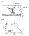
- FIG. 1 is a plan view of a glass antenna 500 for a vehicle according to an embodiment of the invention.
- the glass antenna 500 includes an antenna conductor and a feeding part provided in/on a window glass 12 for a vehicle.
- the glass antenna 500 has a structure including, as the antenna conductor, a first antenna element of an antenna element 1 extending from the feeding part 18 in a first direction substantially perpendicular to the horizontal direction; a second antenna element of an antenna element 2 extending in a second direction substantially perpendicular to the first direction (namely, in the horizontal direction) from an end point 1g corresponding to the end of the extension in the first direction of the antenna element 1; a third antenna element of an antenna element 3 extending in a third direction, that is, the opposite direction to the first direction (namely, a direction parallel to and opposite to the first direction, i.e., the upward direction opposite to the first direction by 180 degrees, in FIG.
- each corner of the antenna conductor may be bent with a curvature.
- the end point may be an end of extension of an antenna element or a conductor portion disposed before and in the vicinity of the end.
- the glass antenna 500 is a monopole antenna, and a received signal obtained by the antenna conductor may be taken out from a positive side (a hot side) of the feeding part 18, and the thus obtained received signal is transmitted to a receiver (not shown).
- a vehicle body opening on which the window glass 12 is mounted or a portion in the vicinity of the body opening is preferably usable as ground (because what is called body earth may be thus attained).
- the glass antenna 500 is suitably used when the feeding part 18 is disposed in the vicinity of an upper or lower flange of the vehicle body opening. In the exemplary case of FIG. 1 , the feeding part 18 is disposed in the vicinity of an upper flange 15e of the body opening.
- the feeding part 18 is a feeding point to which a feeder line connected to the receiver is electrically connected.
- a feeder line When an AV line is used as the feeder line, the feeding part 18 is connected to an amplifier provided on the vehicle for attaining body earth through ground of the amplifier.
- the AV line is easily attached to the feeding part 18.
- the feeding part 18 is electrically connected to an internal conductor of a coaxial cable, and an external conductor of the coaxial cable is electrically connected to the earth part 19.
- the coaxial cable may be easily attached to the feeding part 18 and the earth part 19.
- the earth part 19 may be disposed around and in the vicinity of the feeding part 18 so as not to come in contact with the feeding part 18 and the antenna conductor such as the antenna element 1 electrically connected to the feeding part 18.
- the earth part 19 is disposed on the right-hand side of and to be spaced from the feeding part 18.
- the earth part 19 may be disposed on the left-hand side of and to be spaced from the feeding part 18.
- the ground of the amplifier circuit may be electrically connected to a ground portion such as the external conductor of the coaxial cable with the input side of the amplifier circuit electrically connected to the feeding part 18 and with the output side of the amplifier circuit connected to the internal conductor of the coaxial cable.
- the shape of the feeding part 18 may be determined in accordance with the shape of a leading end of the feeder line directly attached to the feeding part 18 or the shape of a connection member used for connecting the feeder line to the feeding part 18 (for example, in accordance with the shape of a mounting surface or a contact terminal of a connector).
- a rectangular or polygonal shape such as a square, an approximate square, a rectangle or an approximate rectangle is preferred from the viewpoint of implementation.
- the feeding part 18 may be in a circular shape such as a circle, an approximate circle, an ellipse or an approximate ellipse.
- the shape of the earth part 19 illustrated in FIG. 13 may be also determined in the same manner as the shape of the feeding part 18. Also, a distance between the feeding part 18 and the earth part 19 may be determined in accordance with the shapes of leading ends of feeder lines directly attached to the feeding part 18 and the earth part 19 or the shapes of connection members used for connecting the feeder lines to the feeding part 18 and the earth part 19 (for example, in accordance with the shapes of mounting surfaces or contact terminals of connectors).
- the feeding part 18 is in a rectangular shape.
- a connection point 1s connected to the antenna element 1 is disposed on the lower side of the feeding part 18.
- the connection point 1s of FIG. 1 is disposed at the center on the lower side of the feeding part 18, it may be disposed in an arbitrary position on the lower side or disposed on the point of intersection of the lower side with the right or left side.
- the antenna element 1 may extend from the connection point 1s in the downward direction (i.e., in the first direction) to the end point 1g.
- the antenna element 2 may extend from the end point 1g in the leftward direction (i.e., in the second direction) to the end point 2g. Alternatively, it may extend in the rightward direction (namely, in a direction opposite to the second direction by 180 degrees).
- the extending direction of the antenna element 2 (namely, the second direction) is preferably parallel or substantially parallel to the horizontal direction with the window glass 12 mounted on the body opening because the antenna gain may be thus improved as compared with the case where the direction is not parallel.
- the antenna element 3 may extend from the end point 2g in the upward direction (i.e., the third direction) to the end point 3g.
- the antenna element 4 may extend from the end point 3g in the leftward direction (i.e., the second direction) to the end point 4g.
- the antenna element 4 may extend in the rightward direction in the same manner as the antenna element 2.
- FIG. 1 illustrates a right upper area of the backlite 12 provided with the glass antenna of this invention.
- a plurality of heater lines and a plurality of bus bars for supplying power to the plural heater lines are provided, and the plural heater lines and the plural bus bars together form a defogger 30.
- a reference numeral 30a denotes an uppermost heater line
- a reference numeral 30b denotes a bus bar disposed on one side.
- the glass antenna 500 is disposed in a vacant area on the upper side of the defogger 30 with the antenna element 2 extending in parallel to the uppermost heater line 30a.
- the total length corresponding to a sum of a conductor length x1 of the antenna element 1, a conductor length x2 of the antenna element 2, a conductor length x3 of the antenna element 3 and a conductor length x4 of the antenna element 4 is preferably 0.25 ⁇ g1 through 0.41 ⁇ g1 and more preferably 0.27 ⁇ g1 through 0.39 ⁇ g1 because thus, the antenna gain may be preferably improved, so that waves of both the
- the total length i.e., x1 + x2 + x3 + x4
- the waves of the second broadcasting frequency band higher than the first broadcasting frequency band may be also received with high sensitivity.
- the center frequency is 207 MHz, and the wavelength ⁇ g1 at 207 MHz, is 927.5 mm
- the L band of 1452 through 1492 MHz
- the center frequency is 1472 MHz
- the wavelength ⁇ g2 at 1472 MHz is 130.4 mm.
- the total length (i.e., x1 + x2 + x3 + x4) is preferably specifically 230 through 380 mm (and more preferably 250 through 360 mm) from the viewpoint of improvement of the antenna gain in the band III and the L band.
- the conductor length x1 of the antenna element 1 is preferably 0.075 ⁇ g1 through 0.16 ⁇ g1 and more preferably 0.086 ⁇ g1 through 0.13 ⁇ g1 because thus, the antenna gain may be preferably improved, so that the waves of both the first broadcasting frequency band and the second broadcasting frequency band may be received with high sensitivity.
- the conductor length x1 is preferably 70 mm through 150 mm and more preferably 80 mm through 120 mm from the viewpoint of the improvement of the antenna gain.
- the conductor length x3 of the antenna element 3 is preferably 0.086 ⁇ g1 or less and more preferably 0.075 ⁇ g1 or less because thus, the antenna gain in the band III may be preferably improved.
- the conductor length x3 is preferably 80 mm or less and more preferably 70 mm or less from the viewpoint of the improvement of the antenna gain in the band III.
- the antenna gain in the first broadcasting frequency band may be preferably improved.
- the conductor length x3 is preferably 60 mm or more from the viewpoint of the improvement of the antenna gain in the band III.
- the antenna element 4 disposed in the vicinity of the flange of the body opening is preferably provided with a minimum distance from the flange of the body opening of 27 mm or more.
- a minimum distance w01 between an upper flange 15a and the antenna element 4 is preferably 27 mm or more.
- an antenna pattern in which the antenna element of the pattern of FIG. 1 is further folded as illustrated in FIG. 3 may be employed as the antenna pattern attaining high antenna gain in both the first broadcasting frequency band and the second broadcasting frequency band.
- FIG. 3 is a plan view of a glass antenna 600 for a vehicle according to an embodiment of the invention.
- the glass antenna 600 has a structure including, as the antenna conductor, antenna elements 1, 2, 3 and 4; a fifth antenna element of an antenna element 5 extending in the third direction from the end point 4g corresponding to the end of the extension in the second direction of the antenna element 4; and a sixth antenna element of an antenna element 6 extending in a fourth direction, that is, a direction opposite to the second direction (i.e., a direction parallel to and opposite to the second direction, namely, the rightward direction opposite to the second direction by 180 degrees, in FIG.
- a direction opposite to the second direction i.e., a direction parallel to and opposite to the second direction, namely, the rightward direction opposite to the second direction by 180 degrees
- the antenna element 6 extends to the end point 6g in a portion spaced from the feeding part 18 and the antenna element 1 so as not to cross the feeding part 18 and the antenna element 1.
- the total length corresponding to a sum of a conductor length x1 of the antenna element 1, a conductor length x2 of the antenna element 2, a conductor length x3 of the antenna element 3, a conductor length x4 of the antenna element 4, a conductor length x5 of the antenna element 5 and a conductor length x6 of the antenna element 6 is preferably 0.25 ⁇ g1 through 0.41 ⁇ g1 and
- the total length i.e., x1 + x2 + x3 + x4 + x5 + x6
- the waves of the second broadcasting frequency band higher than the first broadcasting frequency band may be received with high sensitivity.
- the total length (i.e., x1 + x2 + x3 + x4 + x5 + x6) is preferably specifically 230 through 380 mm (and more preferably 250 through 360 mm) from the viewpoint of the improvement of the antenna gain in the band III and the L band.
- the antenna element 6 disposed in the vicinity of the flange of the body opening is preferably provided with a minimum distance from the flange of the body opening of 27 mm or more.
- a minimum distance w02 between an upper flange 15a and the antenna element 6 is preferably 27 mm or more.
- an antenna pattern in which an independent conductor 20D is provided so as to closely surround the antenna conductor 500 of FIG. 1 may be employed as the antenna pattern with high antenna gain in both the first broadcasting frequency band and the second broadcasting frequency band.
- the independent conductor 20D may be provided closely on a second direction side alone or on a fourth direction side alone of the antenna conductor 500.
- FIG. 4 is a diagram illustrating a pattern including the independent conductor 20D in the shape of surrounding the antenna conductor 500 including the antenna elements 1, 2, 3 and 4.
- the independent conductor 20D corresponds to a parasitic conductor for the antenna conductor 500.
- the independent conductor 20D may be, for example, an AM glass antenna for receiving AM broadcasting disposed in a vacant area above the defogger 30.
- the independent conductor 20D (that is, the AM antenna in the exemplary case of FIG. 4 ) not DC connected to but disposed close to the antenna conductor 500 is provided in a vacant area of the window glass 12, and the independent conductor 20D is preferably provided in a vacant area disposed on the second direction side of the antenna element 3 and in a vacant area disposed on the fourth direction side of the antenna element 1 because the antenna gain in the band III and the L band may be thus improved.
- the antenna conductor 500 and the independent conductor 20D are preferably capacitatively coupled.
- the independent conductor 20D preferably includes a plurality of liner conductors extending in parallel to the second direction and electrically connected to a second feeding part (not shown in FIG. 4 and corresponding to, for example, a feeding part for an AM antenna) different from the feeding part 18, and thus, the independent conductor 20D may be preferably used for receiving waves of the frequency band of the AM broadcasting.
- the antenna pattern of the independent conductor 20D provided as the AM antenna surrounds the first direction side, the second direction side and the fourth direction side of the antenna conductor 500 as a whole.
- the antenna conductor 500 is disposed in a vacant area 13 whose first direction side, second direction side and fourth direction side are surrounded with the pattern of the AM antenna.
- the independent conductor 20D includes a first liner conductor group composed of a plurality of liner conductors 21 through 26 disposed in the vacant area on the second direction side of the antenna element 3 and a second liner conductor group composed of a plurality of liner conductors 51 through 55 and 26 disposed in the vacant area on the fourth direction side of the antenna element 1.
- the liner conductor 26 runs through a vacant area disposed between the antenna element 2 and the defogger 30 so as to be provided in both the vacant area on the second direction side and the vacant area on the fourth direction side.
- the vacant area 13 where the antenna conductor 500 is provided is surrounded with the first liner conductor group and the second liner conductor group.
- reference numerals 21g through 25 g respectively denote leading ends (end points) opposing the antenna conductor 500 corresponding to ends of extension in the fourth direction of the liner conductors 21 through 25.
- Reference numerals 51g through 55g respectively denote leading ends (end points) opposing the antenna conductor 500 corresponding to ends of extension in the second direction of the liner conductors 51 through 55.
- the plural liner conductors included in the independent conductor 20D may have at least one short-circuit portion formed by connecting a leading end opposing the antenna conductor 500 of one liner conductor of a pair of adjacent liner conductors out of the plural liner conductors to the other liner conductor of the pair through a short-circuit line.
- one short-circuit portion is formed by connecting the leading end 21g and the leading end 22g to each other through a short-circuit line extending in a direction parallel to the first direction.
- one short-circuit portion is formed by connecting the leading end 55g and the liner conductor 26 to each other through a short-circuit line.
- a length in the first direction of first direction components that is, spaces sandwiched between adjacent liner conductors
- a short-circuit line connected to a leading end closest to the periphery of the window glass out of all leading ends opposing the antenna conductor of the plural liner conductors is preferably 0.027 ⁇ g1 or less, and thus, the antenna gain in the first broadcasting frequency band such as the band III may be improved.
- the length is more preferably 0.022 ⁇ g1 or less.
- a length in the first direction of first direction components corresponding to a short-circuit line connected to a leading end closest to the periphery of the window glass out of all leading ends opposing the antenna conductor of the plural liner conductors is preferably 25 mm or less and more preferably 20 mm or less from the viewpoint of the improvement of the antenna gain in the band III.
- the closest antenna element preferably overlaps the closest liner conductor, when the closest liner conductor is projected in the first direction, by a length of 0.043 ⁇ g1 or less and more preferably 0.011 ⁇ g1 or less because thus, the antenna gain in the first broadcasting frequency band
- all liner conductors having leading ends opposing the antenna conductor out of the plural liner conductors are preferably not DC connected in the direction parallel to the first direction, namely, are preferably all opened (as open ends) from the viewpoint of the improvement of the antenna gain.
- Each open end corresponds to a portion opened toward the antenna conductor in the vehicle width direction and is provided between a leading end opposing the antenna conductor of one liner conductor of a pair of adjacent liner conductors out of the plural liner conductors and the other liner conductor of the pair.
- one open end opened toward the antenna conductor is formed between the leading end 21g and the leading end 22g.
- one open end opened toward the antenna conductor is formed between the leading end 55g and the liner conductor 26.
- the aforementioned glass antenna is not provided with an auxiliary antenna conductor, which does not limit the invention.
- An auxiliary antenna element in a substantially T-shape, a substantially L-shape or a loop shape may be added through or not through a connection conductor to an antenna element for impedance matching, phase adjustment, directivity adjustment or the like.
- the glass antenna may include, for example, an auxiliary antenna conductor 7.
- the auxiliary antenna conductor 7 provided on the window glass 12 extends from the lower side of the feeding part 18 in the downward direction (i.e., in the first direction) in parallel to the antenna element 1 in an area on the second direction side (i.e., on the left-hand side) of the extending direction of the antenna element 1 to a point before the antenna element 2.
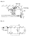
- a glass antenna 700 for a vehicle of FIG. 13 is a dipole antenna capable of taking out a received signal obtained by the antenna conductor from the feeding part 18 on the positive side (hot side) with the earth part 19 on the negative side (cold side) used as ground reference, and the thus obtained received signal is transmitted to a receiver (not shown).
- the feeding part 18 and the earth part 19 may be arranged along the flange of the body opening on which the window glass 12 is mounted.
- the dipole antenna is suitably employed from the viewpoint of not only the improvement of the receiving performance but also the degree of freedom in pattern arrangement.
- a glass antenna may be obtained by forming a conductive layer including an antenna conductor in or on a synthetic resin film and attaching the synthetic resin film having the conductive layer onto the interior or exterior surface of a window glass plate for a vehicle.
- a glass antenna may be obtained by attaching a flexible circuit board on which an antenna conductor has been formed onto the interior or exterior surface of a window glass plate for a vehicle.
- An angle at which the window glass plate is mounted on a vehicle is preferably 15 through 90 degrees and more preferably 30 through 90 degrees against the horizontal direction.
- An antenna conductor is formed by printing a paste including a conductive metal, such as a silver paste, onto the interior surface of a window glass plate and baking the printed paste.
- the method for forming an antenna conductor is not limited to this. Instead, a line or a foil of a conductive substance such as copper may be formed on the interior or exterior surface of a window glass plate, may be adhered onto a window glass with an adhesive or the like, or may be formed within a window glass.
- the feeding part 18 may be similarly formed.
- a part or the whole of an antenna conductor may be formed on the masking film.
- An example of the masking film is a ceramic film such as a black ceramic film.
- the portion of the antenna conductor formed on the masking film is invisible from the outside of the vehicle due to the masking film, resulting in obtaining a window glass with superior design.
- a portion including thin lines alone is visible from the outside of the vehicle, and hence, the resultant window glass is preferred from the viewpoint of design.
- a vehicle high frequency glass antenna fabricated by providing the pattern of the glass antenna 500 of FIG. 1 in a right upper portion seen from the inside of a vehicle of an actual backlite of the vehicle, the antenna gain of the glass antenna attained all around the vehicle is measured so as to obtain average antenna gain with the conductor length x3 of the antenna element 3 varied.
- the respective dimensions of the glass antenna 500 illustrated in FIG. 1 are as follows:
- the antenna gain is measured by radiating, with radio waves, the vehicle on which the window glass is mounted at 15 degrees against the horizontal direction with the vehicle rotated by 360 degrees per angle of 2 degrees.
- the radio waves are vertical polarization and varied in the frequency by 10 MHz in each of the ranges of the band III and the L band.
- the measurement is performed with the wave angle between the position for emitting the waves and the antenna conductor set to the horizontal direction (namely, with the wave angle set to 0 degree assuming that a plane parallel to the ground surface is regarded as 0 degree and that a direction toward the vertex is regarded as 90 degrees).
- the antenna gain is expressed with that of a half-wave dipole antenna as a reference (in both the band III and the L band) and is standardized with the gain of a half-wave dipole antenna regarded as 0 dB.
- FIG. 2 illustrates actually measured data of average values of the antenna gain obtained in the aforementioned manner with the conductor length x3 of the antenna element 3 varied.
- the antenna gain indicated by the ordinate corresponds to an average value of the antenna gain attained at every 10 MHz in the frequency band of 170 through 240 MHz corresponding to the band III and an average value of the antenna gain attained at every 10 MHz in the frequency band of 1450 through 1490 MHz corresponding to the L band.
- the antenna gain is larger. Accordingly, when the conductor length x3 of the antenna element 3 is set to 80 mm or less (and more preferably 70 mm or less), high antenna gain may be attained.
- a vehicle high frequency glass antenna is fabricated by providing the pattern of the glass antenna 500 surrounded with the independent conductor 20D on an actual backlite, and the antenna gain of the glass antenna 500 attained all around the vehicle is measured so as to obtain average antenna gain with a short-circuit portion of the independent conductor 20D varied.
- the basic dimensions of the respective portions of the independent conductor 20D of FIG. 4 are as follows:
- each of patterns of AM glass antennas 20E through 20H illustrated in FIGS. 5A through 5D is provided around the pattern of the glass antenna 500, and vehicle high frequency glass antennas respectively employing these patterns are fabricated.
- the omitted portions are the same as those illustrated in FIG. 4 .
- the antenna gain of each antenna attained all around the vehicle is measured so as to calculate average antenna gain.
- the antenna gain is measured in the same manner as in Example 1.
- FIG. 6 illustrates actually measured data of average values of the antenna gain of the glass antenna 500 attained by employing the respective patterns of the independent conductor.
- "0” corresponds to data obtained by employing the pattern of FIG. 4 in which all the leading ends opposing the glass antenna 500 of the liner conductors are not DC short-circuited along the direction parallel to the first direction and have open ends opened toward the glass antenna along the vehicle width direction.
- "20" corresponds to data obtained by employing the pattern of FIG.
- the sum in length of first direction components closed by short-circuit lines corresponds to 100% of the total length of all first direction components formed between adj acent liner conductors out of the plural liner conductors.
- the sum in length of short-circuit portions corresponds to 80%
- the sum in length of short-circuit portions corresponds to 40%
- the pattern of FIG. 5D it corresponds to 20%.
- the antenna gain in the band III is improved even though the liner conductors 22 through 26 (or 52 through 56) are connected to a short-circuit line (as in the case of "80" of FIG. 6 ).
- the short-circuit line is preferably short.
- the total length of first direction components corresponding to a short-circuit line connected to the leading end 21g (or 51g) closest to a periphery 12a of the vehicle glass window 12 is preferably 0.027 ⁇ g1 or less and more preferably 0.022 ⁇ g1 or less from the viewpoint of the improvement of the antenna gain in the band III.
- the total length is preferably 25 mm or less and more preferably 20 mm or less.
- the antenna gain of the glass antenna 500 attained all around the vehicle is measured so as to calculate average antenna gain with an overlap length w18 in the vertical direction between the uppermost liner conductor 21 and the antenna element 4 varied.
- FIG. 8 illustrates actually measured data of average values of antenna gain of the glass antenna 500 with the length w18 varied. It is noted that the antenna gain indicated by the ordinate corresponds to an average value of the antenna gain attained at every 10 MHz in the frequency band of 170 through 240 MHz corresponding to the band III or an average value of antenna gain attained at every 10 MHz in the frequency band of 1450 through 1490 MHz corresponding to the L band.
- the antenna gain in the band III is improved by setting the overlap length w18 to 40 mm or less and more preferably to 10 mm or less.
- the overlap length w18 is preferably less than 0 mm, namely, they do not preferably overlap, from the viewpoint of the improvement of the antenna gain in the band III.
- vehicle high frequency glass antennas are fabricated by respectively employing a pattern in which the glass antenna 600 is surrounded with an independent conductor 20I and a pattern in which the glass antenna 600 is not provided with an independent conductor, and the antenna gain of the glass antenna 600 attained all around the vehicle is measured so as to calculate average antenna gain with a short-circuit portion of the independent conductor 20I varied.
- the antenna gain is measured in the same manner as in Example 1.
- FIG. 9 is a diagram illustrating the pattern including the independent conductor 20I.
- the basic dimensions of respective portions of the independent conductor 20I are as follows:
- FIG. 10 illustrates actually measured data of average values of the antenna gain of the glass antennas 600 with the pattern of the independent conductor varied.
- "Open” corresponds to data obtained by employing the pattern of FIG. 9 in which all leading ends of the liner conductors opposing the pattern of the glass antenna 600 are not DC short-circuited in the direction parallel to the first direction but have open ends opened toward the glass antenna 600 in the vehicle width direction.
- “Short” corresponds to data obtained by employing a pattern in which all leading ends of the liner conductors opposing the pattern of the glass antenna 600 are DC short-circuited in the direction parallel to the first direction without forming any open end in the pattern of FIG. 9 .
- “Without-AM” corresponds to data obtained by employing the pattern of FIG. 3 without providing the independent conductor.
- the antenna gain in the band III and the L band may not be improved depending upon the pattern of the independent conductor.
- Example 4 when all the leading ends of the independent conductor are short-circuited, the antenna gain is degraded as compared with the case where the independent conductor is not provided, but when all the leading ends of the independent conductor are opened, the antenna gain in the band III and the L band is preferably improved to the equivalent level to that attained without providing the independent conductor.
- an antenna conductor may be surrounded with an independent conductor as illustrated in FIG. 11 .
- a liner conductor 21 of an independent conductor 20J extends to a vacant area above the antenna element 6.
- FIG. 12 illustrates actually measured data of average values of antenna gain of the glass antenna 600 attained without providing it with the independent conductor and attained by surrounding it with the independent conductor.
- “Open” corresponds to data obtained by employing the pattern of FIG. 11 in which all leading ends of the liner conductors opposing the pattern of the glass antenna 600 are not DC short-circuited in the direction parallel to the first direction and have open ends opened toward the glass antenna 600 in the vehicle width direction.
- “Without-AM” corresponds to data obtained by employing the pattern of FIG. 3 not provided with the AM glass antenna.
- the antenna gain in both the band III and the L band is improved as compared with the case where the independent conductor is not provided.
- the antenna gain of the glass antenna 700 of FIG. 13 attained all around the vehicle is measured so as to obtain average antenna gain with or without providing the auxiliary antenna conductor 7. Furthermore, the antenna gain of the glass antenna 700 attained all around the vehicle is measured so as to obtain average antenna gain with or without providing a matching circuit M illustrated in FIG. 14 .
- FIG. 14 is a circuit diagram of the matching circuit M.
- Za indicates input impedance of the antenna conductor provided in the window glass on the basis of the feeding part 18 and the earth part 19.
- the input impedance Za of the antenna conductor parasitically has an inductance component along the extending direction of a line of the antenna conductor and parasitically has a capacitance component between lines of the antenna conductor.
- the inductance component and the capacitance component are not well balanced, a resonance frequency is shifted, resulting in matching degradation and narrow band.
- the matching circuit M is additionally provided.
- the matching circuit M is additionally provided, the balance between the inductance component and the capacitance component included in the input impedance Za may be adjusted.
- the matching circuit M is an LC circuit obtained by connecting a capacitor C and an inductor L to each other.
- the capacitor C is a capacitative element serially inserted in the antenna conductor serially connected to the feeding part 18.
- the inductor L is an inductive element inserted in parallel between lines of the feeding part 18 and the earth part 19.
- the matching circuit M includes terminals 61 through 64 corresponding to contact points with external circuits. One end of the capacitor C is connected to the terminal 61 and the other end thereof is connected to the terminal 63. One end of the inductor L is connected to the terminal 63 and the other end thereof is connected to the terminals 62 and 64.
- a signal line (an internal conductor) 71 of a coaxial cable 70 connected to a signal processor such as an amplifier is connected to the terminal 61, one end of a ground line (an eternal conductor) 72 of the coaxial cable 70 is connected to the terminal 62, and the other end of the ground line 72 of the coaxial cable 70 is connected to an earth portion of the vehicle or the like.
- the terminal 63 of the matching circuit M is mounted on the feeding part 18 through solder or the like, and the terminal 64 is mounted on the earth part 19 through solder or the like.
- the signal line 71 of the coaxial cable 70 connected to the signal processor such as an amplifier is directly connected to the feeding part 18, one end of the ground line 72 is directly connected to the earth part 19 and the other end of the ground line 72 is connected to the earth portion of the vehicle or the like.
- Table 1 illustrates actually measured data of average values of the antenna gain of the glass antenna 700 attained with/without providing the matching circuit M and the auxiliary conductor 7.
- an average value of the antenna gain in the band III is an average value of the antenna gain measured at every 10 MHz in 170 through 240 MHz
- an average value of the antenna gain in the L band is an average value of the antenna gain measured at every 10 MHz in 1450 through 1490 MHz.
- the dimensions of the respective portions of the glass antenna 700 of FIG. 13 are as follows:
- the antenna gain in the L band is improved as compared with the case where it is not provided. Also, when the matching circuit M is provided, the antenna gain in the band III may be improved as compared with the case where it is not provided.
Landscapes
- Details Of Aerials (AREA)
Abstract
Description
- The present invention relates to a glass antenna for a vehicle whose antenna conductor and feeding part are provided in/on a window glass for a vehicle. Also, the present invention relates to a window glass for a vehicle, including the glass antenna.
- As related arts, glass antennas for a vehicle capable of receiving digital audio broadcasting (DAB) described in, for example,
JP-A-H10-327009 JP-A-2000-307321 - For coping with a dual frequency band such as the DAB, however, desired bands are away from each other, and therefore, it is difficult to design and fabricate a glass antenna for a vehicle, which has sufficient receiving performance applicable to the both bands.
- An object of the invention is providing a glass antenna for a vehicle, which has a receiving characteristic applicable to a dual band such as the DAB, and a window glass for a vehicle, including the glass antenna for the vehicle.
- In order to achieve the object, according to an aspect of the invention, there is provided a glass antenna for a vehicle, including: a feeding part provided in or on a window glass for the vehicle; and an antenna conductor, provided in or on the window glass, the antenna conductor including: a first antenna element, extending in a first direction from the feeding part; a second antenna element, extending in a second direction substantially perpendicular to the first direction from an end of extension of the first antenna element; a third antenna element, extending in a third direction opposite to the first direction from an end of extension of the second antenna element; and a fourth antenna element, extending in the second direction from an end of extension of the third antenna element.
- Alternatively, the antenna conductor may further include a fifth antenna element extending in the third direction from an end of extension of the fourth antenna element; and a sixth antenna element extending in a fourth direction opposite to the second direction from an end of extension of the fifth antenna element.
- Furthermore, the present invention provides a window glass for a vehicle, including the glass antenna of the invention.
- According to the present invention, a receiving characteristic applicable to a dual band such as the DAB may be attained.
- The present invention will become more fully understood from the detailed description given hereinbelow and the accompanying drawing which is given by way of illustration only, and thus is not limitative of the present invention and wherein:
-
FIG. 1 is a plan view of aglass antenna 500 for a vehicle according to an embodiment of the invention. -
FIG. 2 is a diagram illustrating actually measured data of average values of antenna gain attained with a conductor length x3 varied. -
FIG. 3 is a plan view of aglass antenna 600 for a vehicle according to another embodiment of the invention. -
FIG. 4 is a diagram illustrating a pattern of theglass antenna 500 and an AM glass antenna. -
FIGS. 5A, 5B, 5C and 5D are diagrams illustrating other patterns of theglass antenna 500 and the AM glass antenna. -
FIG. 6 is a diagram illustrating actually measured data of average values of antenna gain of theglass antenna 500 attained with various patterns of the AM glass antenna. -
FIG. 7 is a diagram illustrating a pattern in which anuppermost liner conductor 21 overlaps anantenna element 4. -
FIG. 8 is a diagram illustrating actually measured data of average values of antenna gain of theglass antenna 500 attained with a length w18 varied. -
FIG. 9 is a diagram illustrating a pattern of theglass antenna 600 and an AM glass antenna. -
FIG. 10 is a diagram illustrating actually measured data of average values of antenna gain of theglass antenna 600 attained with a short-circuit portion varied. -
FIG. 11 is a diagram illustrating a pattern in which theglass antenna 600 is wholly surrounded. -
FIG. 12 is a diagram illustrating actually measured data of average values of antenna gain of theglass antenna 600 attained with or without the AM glass antenna. -
FIG. 13 is a plan view of aglass antenna 700 for a vehicle according to another embodiment of the invention. -
FIG. 14 is a circuit diagram of a matching circuit M. - Embodiments for carrying out the invention will be described with reference to the accompanying drawings. It is noted that a direction mentioned with reference to a drawing used for explaining an embodiment means a direction.on the drawing unless otherwise mentioned. Also, such a drawing is a view taken from an opposing direction to the surface of a window glass and seen from the inside (or the outside) of a vehicle with the window glass mounted on the vehicle, and a lateral direction in the drawing corresponds to the horizontal direction. Furthermore, when a window glass to be described is, for example, a backlite mounted on a rear part of a vehicle, a lateral direction in the drawing corresponds to the vehicle width direction. Incidentally, the present invention is not limited to a backlite but is applicable to a windscreen mounted on a front part of a vehicle or a side window mounted on a side part of a vehicle. Furthermore, a direction herein designated as a parallel or perpendicular direction may allow slight shift as far as the effects of the invention are not spoiled.
-
FIG. 1 is a plan view of aglass antenna 500 for a vehicle according to an embodiment of the invention. Theglass antenna 500 includes an antenna conductor and a feeding part provided in/on awindow glass 12 for a vehicle. Theglass antenna 500 has a structure including, as the antenna conductor, a first antenna element of anantenna element 1 extending from thefeeding part 18 in a first direction substantially perpendicular to the horizontal direction; a second antenna element of anantenna element 2 extending in a second direction substantially perpendicular to the first direction (namely, in the horizontal direction) from anend point 1g corresponding to the end of the extension in the first direction of theantenna element 1; a third antenna element of anantenna element 3 extending in a third direction, that is, the opposite direction to the first direction (namely, a direction parallel to and opposite to the first direction, i.e., the upward direction opposite to the first direction by 180 degrees, inFIG. 1 ) from anend point 2g corresponding to the end of the extension in the second direction of theantenna element 2; and a fourth antenna element of anantenna element 4 extending in the second direction from anend point 3g corresponding to the end of the extension in the third direction of theantenna element 3 to anend point 4g. It is noted that each corner of the antenna conductor may be bent with a curvature. Also, the end point may be an end of extension of an antenna element or a conductor portion disposed before and in the vicinity of the end. - The
glass antenna 500 is a monopole antenna, and a received signal obtained by the antenna conductor may be taken out from a positive side (a hot side) of thefeeding part 18, and the thus obtained received signal is transmitted to a receiver (not shown). In providing the glass antenna as a monopole antenna, a vehicle body opening on which thewindow glass 12 is mounted or a portion in the vicinity of the body opening is preferably usable as ground (because what is called body earth may be thus attained). Theglass antenna 500 is suitably used when thefeeding part 18 is disposed in the vicinity of an upper or lower flange of the vehicle body opening. In the exemplary case ofFIG. 1 , thefeeding part 18 is disposed in the vicinity of an upper flange 15e of the body opening. - The
feeding part 18 is a feeding point to which a feeder line connected to the receiver is electrically connected. When an AV line is used as the feeder line, thefeeding part 18 is connected to an amplifier provided on the vehicle for attaining body earth through ground of the amplifier. At this point, when a connector for electrically connecting the AV line to thefeeding part 18 is mounted on thefeeding part 18, the AV line is easily attached to thefeeding part 18. - When the
window glass 12 is provided with an earth part 19 (see, for example,FIG. 13 ), thefeeding part 18 is electrically connected to an internal conductor of a coaxial cable, and an external conductor of the coaxial cable is electrically connected to theearth part 19. When connectors for electrically connecting the coaxial cable to thefeeding part 18 and theearth part 19 are mounted on thefeeding part 18 and theearth part 19, the coaxial cable may be easily attached to thefeeding part 18 and theearth part 19. - The
earth part 19 may be disposed around and in the vicinity of thefeeding part 18 so as not to come in contact with thefeeding part 18 and the antenna conductor such as theantenna element 1 electrically connected to thefeeding part 18. In the exemplary case illustrated inFIG. 13 , theearth part 19 is disposed on the right-hand side of and to be spaced from thefeeding part 18. Theearth part 19 may be disposed on the left-hand side of and to be spaced from thefeeding part 18. - When the connector mounted on the
feeding part 18 includes an amplifier circuit for amplifying a received signal taken out from thefeeding part 18, the ground of the amplifier circuit may be electrically connected to a ground portion such as the external conductor of the coaxial cable with the input side of the amplifier circuit electrically connected to thefeeding part 18 and with the output side of the amplifier circuit connected to the internal conductor of the coaxial cable. - The shape of the
feeding part 18 may be determined in accordance with the shape of a leading end of the feeder line directly attached to thefeeding part 18 or the shape of a connection member used for connecting the feeder line to the feeding part 18 (for example, in accordance with the shape of a mounting surface or a contact terminal of a connector). A rectangular or polygonal shape such as a square, an approximate square, a rectangle or an approximate rectangle is preferred from the viewpoint of implementation. Thefeeding part 18 may be in a circular shape such as a circle, an approximate circle, an ellipse or an approximate ellipse. - The shape of the
earth part 19 illustrated inFIG. 13 may be also determined in the same manner as the shape of thefeeding part 18. Also, a distance between thefeeding part 18 and theearth part 19 may be determined in accordance with the shapes of leading ends of feeder lines directly attached to thefeeding part 18 and theearth part 19 or the shapes of connection members used for connecting the feeder lines to thefeeding part 18 and the earth part 19 (for example, in accordance with the shapes of mounting surfaces or contact terminals of connectors). - In
FIG. 1 , thefeeding part 18 is in a rectangular shape. Aconnection point 1s connected to theantenna element 1 is disposed on the lower side of thefeeding part 18. Although theconnection point 1s ofFIG. 1 is disposed at the center on the lower side of thefeeding part 18, it may be disposed in an arbitrary position on the lower side or disposed on the point of intersection of the lower side with the right or left side. - The
antenna element 1 may extend from theconnection point 1s in the downward direction (i.e., in the first direction) to theend point 1g. - The
antenna element 2 may extend from theend point 1g in the leftward direction (i.e., in the second direction) to theend point 2g. Alternatively, it may extend in the rightward direction (namely, in a direction opposite to the second direction by 180 degrees). The extending direction of the antenna element 2 (namely, the second direction) is preferably parallel or substantially parallel to the horizontal direction with thewindow glass 12 mounted on the body opening because the antenna gain may be thus improved as compared with the case where the direction is not parallel. - The
antenna element 3 may extend from theend point 2g in the upward direction (i.e., the third direction) to theend point 3g. - The
antenna element 4 may extend from theend point 3g in the leftward direction (i.e., the second direction) to theend point 4g. When theantenna element 2 extends in the rightward direction, theantenna element 4 may extend in the rightward direction in the same manner as theantenna element 2. -
FIG. 1 (taken from the inside or the outside of the vehicle) illustrates a right upper area of thebacklite 12 provided with the glass antenna of this invention. In thebacklite 12, a plurality of heater lines and a plurality of bus bars (merely one of which is illustrated inFIG. 1 ) for supplying power to the plural heater lines are provided, and the plural heater lines and the plural bus bars together form adefogger 30. InFIG. 1 , areference numeral 30a denotes an uppermost heater line and areference numeral 30b denotes a bus bar disposed on one side. InFIG. 1 , theglass antenna 500 is disposed in a vacant area on the upper side of thedefogger 30 with theantenna element 2 extending in parallel to theuppermost heater line 30a. - In the present invention, assuming that the wavelength in the air of a center frequency of a first broadcasting frequency band is indicated by λ01, that the wavelength in the air of a center frequency of a second broadcasting frequency band higher than the first broadcasting frequency band is indicated by λ02, that the shortening coefficient of wavelength by glass is indicated by k (whereas k = 0.64) and that λg1 = λ01·k and λg2 = λ02·k, the total length corresponding to a sum of a conductor length x1 of the
antenna element 1, a conductor length x2 of theantenna element 2, a conductor length x3 of theantenna element 3 and a conductor length x4 of the antenna element 4 (i.e., x1 + x2 + x3 + x4) is preferably 0.25·λg1 through 0.41·λg1 and more preferably 0.27·λg1 through 0.39·λg1 because thus, the antenna gain may be preferably improved, so that waves of both the first broadcasting frequency band and the second broadcasting frequency band may be received with high sensitivity. - In other words, when the pattern shape of the
glass antenna 500 is employed, although the total length (i.e., x1 + x2 + x3 + x4) is determined on the basis of a length for attaining resonation in the first broadcasting frequency band, the waves of the second broadcasting frequency band higher than the first broadcasting frequency band may be also received with high sensitivity. - For example, when the band III (of 174 through 240 MHz) is set as the first broadcasting frequency band, the center frequency is 207 MHz, and the wavelength λg1 at 207 MHz, is 927.5 mm, and when the L band (of 1452 through 1492 MHz) is set as the second broadcasting frequency band, the center frequency is 1472 MHz, and the wavelength λg2 at 1472 MHz is 130.4 mm.
- Accordingly, the total length (i.e., x1 + x2 + x3 + x4) is preferably specifically 230 through 380 mm (and more preferably 250 through 360 mm) from the viewpoint of improvement of the antenna gain in the band III and the L band.
- Furthermore, in the present invention, assuming that there are a desired first broadcasting frequency band and a desired second broadcasting frequency band higher than the first broadcasting frequency band, that the wavelength in the air of a center frequency of the first broadcasting frequency band is indicated by λ01, that the shortening coefficient of wavelength by glass is indicated by k (whereas k = 0.64) and that λg1 = λ01·k, the conductor length x1 of the
antenna element 1 is preferably 0.075·λg1 through 0.16·λg1 and more preferably 0.086·λg1 through 0.13·λg1 because thus, the antenna gain may be preferably improved, so that the waves of both the first broadcasting frequency band and the second broadcasting frequency band may be received with high sensitivity. Specifically, the conductor length x1 is preferably 70 mm through 150 mm and more preferably 80 mm through 120 mm from the viewpoint of the improvement of the antenna gain. - Moreover, in the present invention, assuming that there are a desired first broadcasting frequency band and a desired second broadcasting frequency band higher than the first broadcasting frequency band, that the wavelength in the air of a center frequency of the first broadcasting frequency band is indicated by λ01, that the shortening coefficient of wavelength by glass is indicated by k (whereas k = 0.64) and that λg1 = λ01·k, the conductor length x3 of the
antenna element 3 is preferably 0.086·λg1 or less and more preferably 0.075·λg1 or less because thus, the antenna gain in the band III may be preferably improved. Specifically, the conductor length x3 is preferably 80 mm or less and more preferably 70 mm or less from the viewpoint of the improvement of the antenna gain in the band III. - When the conductor length x3 of the
antenna element 3 is 0.064·λg1 or more, the antenna gain in the first broadcasting frequency band may be preferably improved. Specifically, the conductor length x3 is preferably 60 mm or more from the viewpoint of the improvement of the antenna gain in the band III. - Furthermore, the
antenna element 4 disposed in the vicinity of the flange of the body opening is preferably provided with a minimum distance from the flange of the body opening of 27 mm or more. Thus, the degradation of the antenna gain derived from the influence of the vehicle body may be suppressed. In the exemplary case illustrated inFIG. 1 , a minimum distance w01 between anupper flange 15a and theantenna element 4 is preferably 27 mm or more. - Alternatively, an antenna pattern in which the antenna element of the pattern of
FIG. 1 is further folded as illustrated inFIG. 3 may be employed as the antenna pattern attaining high antenna gain in both the first broadcasting frequency band and the second broadcasting frequency band. -
FIG. 3 is a plan view of aglass antenna 600 for a vehicle according to an embodiment of the invention. InFIG. 3 , like reference numerals are used to refer to like elements used inFIG. 1 and the description is omitted. Theglass antenna 600 has a structure including, as the antenna conductor,antenna elements antenna element 5 extending in the third direction from theend point 4g corresponding to the end of the extension in the second direction of theantenna element 4; and a sixth antenna element of anantenna element 6 extending in a fourth direction, that is, a direction opposite to the second direction (i.e., a direction parallel to and opposite to the second direction, namely, the rightward direction opposite to the second direction by 180 degrees, inFIG. 3 ) from anend point 5g corresponding to the end of the extension in the third direction of theantenna element 5 to an end point 6g. Theantenna element 6 extends to the end point 6g in a portion spaced from the feedingpart 18 and theantenna element 1 so as not to cross the feedingpart 18 and theantenna element 1. - In the present invention, assuming that the wavelength in the air of a center frequency of a first broadcasting frequency band is indicated by λ01, that the wavelength in the air of a center frequency of a second broadcasting frequency band higher than the first broadcasting frequency band is indicated by λ02, that the shortening coefficient of wavelength by glass is indicated by k (whereas k = 0.64) and that λg1 = λ01·k and λg2 = λ02·k, the total length corresponding to a sum of a conductor length x1 of the
antenna element 1, a conductor length x2 of theantenna element 2, a conductor length x3 of theantenna element 3, a conductor length x4 of theantenna element 4, a conductor length x5 of theantenna element 5 and a conductor length x6 of the antenna element 6 (i.e., x1 + x2 + x3 + x4 + x5 + x6) is preferably 0.25·λg1 through 0.41·λg1 and more preferably 0.27·λg1 through 0.39·λg1 because thus, the antenna gain may be preferably improved, so that waves of both the first broadcasting frequency band and the second broadcasting frequency band may be received with high sensitivity. - In other words, when the pattern shape of the
glass antenna 600 is employed, although the total length (i.e., x1 + x2 + x3 + x4 + x5 + x6) is determined on the basis of a length for attaining resonation in the first broadcasting frequency band, the waves of the second broadcasting frequency band higher than the first broadcasting frequency band may be received with high sensitivity. - Accordingly, the total length (i.e., x1 + x2 + x3 + x4 + x5 + x6) is preferably specifically 230 through 380 mm (and more preferably 250 through 360 mm) from the viewpoint of the improvement of the antenna gain in the band III and the L band.
- Furthermore, the
antenna element 6 disposed in the vicinity of the flange of the body opening is preferably provided with a minimum distance from the flange of the body opening of 27 mm or more. Thus, the degradation of the antenna gain derived from the influence of the vehicle body may be suppressed. In the exemplary case illustrated inFIG. 3 , a minimum distance w02 between anupper flange 15a and theantenna element 6 is preferably 27 mm or more. - Alternatively, an antenna pattern in which an
independent conductor 20D is provided so as to closely surround theantenna conductor 500 ofFIG. 1 may be employed as the antenna pattern with high antenna gain in both the first broadcasting frequency band and the second broadcasting frequency band. In this invention, theindependent conductor 20D may be provided closely on a second direction side alone or on a fourth direction side alone of theantenna conductor 500. -
FIG. 4 is a diagram illustrating a pattern including theindependent conductor 20D in the shape of surrounding theantenna conductor 500 including theantenna elements FIG. 4 , like reference numerals are used to refer to like elements used inFIG. 1 and the description is omitted. Theindependent conductor 20D corresponds to a parasitic conductor for theantenna conductor 500. Theindependent conductor 20D may be, for example, an AM glass antenna for receiving AM broadcasting disposed in a vacant area above thedefogger 30. - Specifically, the
independent conductor 20D (that is, the AM antenna in the exemplary case ofFIG. 4 ) not DC connected to but disposed close to theantenna conductor 500 is provided in a vacant area of thewindow glass 12, and theindependent conductor 20D is preferably provided in a vacant area disposed on the second direction side of theantenna element 3 and in a vacant area disposed on the fourth direction side of theantenna element 1 because the antenna gain in the band III and the L band may be thus improved. - From the viewpoint of the improvement of the antenna gain in the band III and the L band, the
antenna conductor 500 and theindependent conductor 20D are preferably capacitatively coupled. - The
independent conductor 20D preferably includes a plurality of liner conductors extending in parallel to the second direction and electrically connected to a second feeding part (not shown inFIG. 4 and corresponding to, for example, a feeding part for an AM antenna) different from the feedingpart 18, and thus, theindependent conductor 20D may be preferably used for receiving waves of the frequency band of the AM broadcasting. - In
FIG. 4 , the antenna pattern of theindependent conductor 20D provided as the AM antenna surrounds the first direction side, the second direction side and the fourth direction side of theantenna conductor 500 as a whole. In other words, theantenna conductor 500 is disposed in avacant area 13 whose first direction side, second direction side and fourth direction side are surrounded with the pattern of the AM antenna. - The
independent conductor 20D includes a first liner conductor group composed of a plurality ofliner conductors 21 through 26 disposed in the vacant area on the second direction side of theantenna element 3 and a second liner conductor group composed of a plurality ofliner conductors 51 through 55 and 26 disposed in the vacant area on the fourth direction side of theantenna element 1. Theliner conductor 26 runs through a vacant area disposed between theantenna element 2 and thedefogger 30 so as to be provided in both the vacant area on the second direction side and the vacant area on the fourth direction side. Thevacant area 13 where theantenna conductor 500 is provided is surrounded with the first liner conductor group and the second liner conductor group. Also,reference numerals 21g through 25 g respectively denote leading ends (end points) opposing theantenna conductor 500 corresponding to ends of extension in the fourth direction of theliner conductors 21 through 25.Reference numerals 51g through 55g respectively denote leading ends (end points) opposing theantenna conductor 500 corresponding to ends of extension in the second direction of theliner conductors 51 through 55. - Furthermore, the plural liner conductors included in the
independent conductor 20D may have at least one short-circuit portion formed by connecting a leading end opposing theantenna conductor 500 of one liner conductor of a pair of adjacent liner conductors out of the plural liner conductors to the other liner conductor of the pair through a short-circuit line. For example, inFig. 4 , one short-circuit portion is formed by connecting theleading end 21g and theleading end 22g to each other through a short-circuit line extending in a direction parallel to the first direction. Also, one short-circuit portion is formed by connecting theleading end 55g and theliner conductor 26 to each other through a short-circuit line. - In forming such a short-circuit portion, assuming that there are a desired first broadcasting frequency band and a desired second broadcasting frequency band higher than the first broadcasting frequency band, that the wavelength in the air of a center frequency of the first broadcasting frequency band is indicated by λ01, that the shortening coefficient of wavelength by glass is indicated by k (whereas k = 0.64) and that λg1 = λ01·k, a length in the first direction of first direction components (that is, spaces sandwiched between adjacent liner conductors) corresponding to a short-circuit line connected to a leading end closest to the periphery of the window glass out of all leading ends opposing the antenna conductor of the plural liner conductors is preferably 0.027·λg1 or less, and thus, the antenna gain in the first broadcasting frequency band such as the band III may be improved. The length is more preferably 0.022·λg1 or less. Specifically, a length in the first direction of first direction components corresponding to a short-circuit line connected to a leading end closest to the periphery of the window glass out of all leading ends opposing the antenna conductor of the plural liner conductors is preferably 25 mm or less and more preferably 20 mm or less from the viewpoint of the improvement of the antenna gain in the band III.
- Furthermore, in this invention, assuming that there are a desired first broadcasting frequency band and a desired second broadcasting frequency band higher than the first broadcasting frequency band, that the wavelength in the air of a center frequency of the first broadcasting frequency band is indicated by λ01, that the shortening coefficient of wavelength by glass is indicated by k (whereas k = 0.64) and that λg1 = λ01·k, as the positional relationship between an antenna element closest to the periphery of the window glass out of all antenna elements included in the antenna conductor and extending in the direction parallel to the second direction and a closest liner conductor, out of plural liner conductors included in the independent conductor, positioned closer to the periphery of the window glass than the closest antenna element, the closest antenna element preferably overlaps the closest liner conductor, when the closest liner conductor is projected in the first direction, by a length of 0.043·λg1 or less and more preferably 0.011·λg1 or less because thus, the antenna gain in the first broadcasting frequency band such as the band III may be improved. Specifically, the overlap length is preferably 40 mm or less and more preferably 10 mm or less, and still more preferably they do not overlap at all from the viewpoint of the improvement of the antenna gain in the band III.
- Moreover, in the present invention, all liner conductors having leading ends opposing the antenna conductor out of the plural liner conductors are preferably not DC connected in the direction parallel to the first direction, namely, are preferably all opened (as open ends) from the viewpoint of the improvement of the antenna gain. Each open end corresponds to a portion opened toward the antenna conductor in the vehicle width direction and is provided between a leading end opposing the antenna conductor of one liner conductor of a pair of adjacent liner conductors out of the plural liner conductors and the other liner conductor of the pair. For example, in
FIG. 4 , one open end opened toward the antenna conductor is formed between theleading end 21g and theleading end 22g. Also, one open end opened toward the antenna conductor is formed between theleading end 55g and theliner conductor 26. - The aforementioned glass antenna is not provided with an auxiliary antenna conductor, which does not limit the invention. An auxiliary antenna element in a substantially T-shape, a substantially L-shape or a loop shape may be added through or not through a connection conductor to an antenna element for impedance matching, phase adjustment, directivity adjustment or the like.
- As illustrated in
FIG. 13 , the glass antenna may include, for example, an auxiliary antenna conductor 7. The auxiliary antenna conductor 7 provided on thewindow glass 12 extends from the lower side of the feedingpart 18 in the downward direction (i.e., in the first direction) in parallel to theantenna element 1 in an area on the second direction side (i.e., on the left-hand side) of the extending direction of theantenna element 1 to a point before theantenna element 2. - Furthermore, the present invention is applicable to a dipole antenna as illustrated in
FIG. 13 . Aglass antenna 700 for a vehicle ofFIG. 13 is a dipole antenna capable of taking out a received signal obtained by the antenna conductor from the feedingpart 18 on the positive side (hot side) with theearth part 19 on the negative side (cold side) used as ground reference, and the thus obtained received signal is transmitted to a receiver (not shown). In the dipole antenna, the feedingpart 18 and theearth part 19 may be arranged along the flange of the body opening on which thewindow glass 12 is mounted. Also, when the flange or a portion in the vicinity of the flange of the body opening of the vehicle on which thewindow glass 12 is mounted cannot be used as the ground (for example, when the portion is electrically floating from the body earth or the body itself is made of a non-conductive material such as a resin), the dipole antenna is suitably employed from the viewpoint of not only the improvement of the receiving performance but also the degree of freedom in pattern arrangement. - Furthermore, a glass antenna may be obtained by forming a conductive layer including an antenna conductor in or on a synthetic resin film and attaching the synthetic resin film having the conductive layer onto the interior or exterior surface of a window glass plate for a vehicle. Alternatively, a glass antenna may be obtained by attaching a flexible circuit board on which an antenna conductor has been formed onto the interior or exterior surface of a window glass plate for a vehicle.
- An angle at which the window glass plate is mounted on a vehicle is preferably 15 through 90 degrees and more preferably 30 through 90 degrees against the horizontal direction.
- An antenna conductor is formed by printing a paste including a conductive metal, such as a silver paste, onto the interior surface of a window glass plate and baking the printed paste. The method for forming an antenna conductor is not limited to this. Instead, a line or a foil of a conductive substance such as copper may be formed on the interior or exterior surface of a window glass plate, may be adhered onto a window glass with an adhesive or the like, or may be formed within a window glass. The feeding
part 18 may be similarly formed. - Furthermore, with a masking film formed on a window glass, a part or the whole of an antenna conductor may be formed on the masking film. An example of the masking film is a ceramic film such as a black ceramic film. In this case, when seen from the outside of the vehicle, the portion of the antenna conductor formed on the masking film is invisible from the outside of the vehicle due to the masking film, resulting in obtaining a window glass with superior design. In employing the structure illustrated in any of the drawings, when at least a part of the feeding part and the antenna conductor is formed on a masking film, a portion including thin lines alone is visible from the outside of the vehicle, and hence, the resultant window glass is preferred from the viewpoint of design.
- In a vehicle high frequency glass antenna fabricated by providing the pattern of the
glass antenna 500 ofFIG. 1 in a right upper portion seen from the inside of a vehicle of an actual backlite of the vehicle, the antenna gain of the glass antenna attained all around the vehicle is measured so as to obtain average antenna gain with the conductor length x3 of theantenna element 3 varied. - In this case, the respective dimensions of the
glass antenna 500 illustrated inFIG. 1 are as follows: - x1: 107 mm
- x2: 10 mm
- x3: 70 mm
- x4: 130 mm
- The antenna gain is measured by radiating, with radio waves, the vehicle on which the window glass is mounted at 15 degrees against the horizontal direction with the vehicle rotated by 360 degrees per angle of 2 degrees. The radio waves are vertical polarization and varied in the frequency by 10 MHz in each of the ranges of the band III and the L band. The measurement is performed with the wave angle between the position for emitting the waves and the antenna conductor set to the horizontal direction (namely, with the wave angle set to 0 degree assuming that a plane parallel to the ground surface is regarded as 0 degree and that a direction toward the vertex is regarded as 90 degrees). The antenna gain is expressed with that of a half-wave dipole antenna as a reference (in both the band III and the L band) and is standardized with the gain of a half-wave dipole antenna regarded as 0 dB.
-
FIG. 2 illustrates actually measured data of average values of the antenna gain obtained in the aforementioned manner with the conductor length x3 of theantenna element 3 varied. Incidentally, inFIG. 2 , the antenna gain indicated by the ordinate corresponds to an average value of the antenna gain attained at every 10 MHz in the frequency band of 170 through 240 MHz corresponding to the band III and an average value of the antenna gain attained at every 10 MHz in the frequency band of 1450 through 1490 MHz corresponding to the L band. - As illustrated in
FIG. 2 , when the conductor length x3 of theantenna element 3 is shorter, the antenna gain is larger. Accordingly, when the conductor length x3 of theantenna element 3 is set to 80 mm or less (and more preferably 70 mm or less), high antenna gain may be attained. - Next, a vehicle high frequency glass antenna is fabricated by providing the pattern of the
glass antenna 500 surrounded with theindependent conductor 20D on an actual backlite, and the antenna gain of theglass antenna 500 attained all around the vehicle is measured so as to obtain average antenna gain with a short-circuit portion of theindependent conductor 20D varied. The basic dimensions of the respective portions of theindependent conductor 20D ofFIG. 4 are as follows: - w1: 375 mm
- w2: 200 mm
- w3 - w7: 20 mm
- w8: 20 mm
- w9: 10 mm
- w10: 10 mm
- w11: 1070 mm
- w12: 150 mm
- w13: 130 mm
- w14: 30 mm
- w15: 175 mm
- w16: 10 mm
- w17: 10 mm
- Furthermore, as alternative patterns of the independent conductor, each of patterns of
AM glass antennas 20E through 20H illustrated inFIGS. 5A through 5D is provided around the pattern of theglass antenna 500, and vehicle high frequency glass antennas respectively employing these patterns are fabricated. In each pattern illustrated inFIGS. 5A through 5D , although the reference numerals, the dimensions and the pattern formed on the left-hand side are partly omitted, the omitted portions are the same as those illustrated inFIG. 4 . - With respect to the vehicle high frequency glass antennas employing the five kinds of patterns of the AM glass antennas illustrated in
FIGS. 4 and5A through5D , the antenna gain of each antenna attained all around the vehicle is measured so as to calculate average antenna gain. The antenna gain is measured in the same manner as in Example 1. -
FIG. 6 illustrates actually measured data of average values of the antenna gain of theglass antenna 500 attained by employing the respective patterns of the independent conductor. In this drawing, "0" corresponds to data obtained by employing the pattern ofFIG. 4 in which all the leading ends opposing theglass antenna 500 of the liner conductors are not DC short-circuited along the direction parallel to the first direction and have open ends opened toward the glass antenna along the vehicle width direction. Also, "20" corresponds to data obtained by employing the pattern ofFIG. 5D in which a short-circuit portion is formed by connecting theleading end 21g (or 51g) closest to theupper flange 15a of the body opening to the liner conductor 22 (or 52) and open ends are formed between theliner conductors liner conductors FIG. 5C in which a short-circuit portion is formed by connecting theleading end 21g (or 51g) closest to theupper flange 15a of the body opening to theliner conductors 22 and 23 (or 52 and 53) and open ends are formed between theliner conductors liner conductors FIG. 5B in which an open end is formed between the liner conductor 21 (or 51) having theleading end 21g (or 51g) closest to theupper flange 15a of the body opening and the liner conductor 22 (or 52) and short-circuit portions are formed between theliner conductors liner conductors FIG. 5A in which all the leading ends opposing theglass antenna 500 of the liner conductors are DC short-circuited in the direction parallel to the first direction so as to form short-circuit portions at all the leading ends without forming any open end. - In the pattern of
FIG. 5A , the sum in length of first direction components closed by short-circuit lines (namely, short-circuit portions) corresponds to 100% of the total length of all first direction components formed between adj acent liner conductors out of the plural liner conductors. In the pattern ofFIG. 5B , the sum in length of short-circuit portions corresponds to 80%, in the pattern ofFIG. 5C , it corresponds to 40%, and in the pattern ofFIG. 5D , it corresponds to 20%. - As illustrated in
FIG. 6 , when the liner conductor 21 (or 51) close to theupper flange 15a of the body opening is connected to a short-circuit line (as in the case of "20" ofFIG. 6 ), the antenna gain in the band III is degraded as compared with the case where all the leading ends have open ends (as in the case of "0" inFIG. 6 ) even though the open ends are formed between theliner conductors 22 through 26 (or 52 through 26). On the other hand, when an open end is formed between the liner conductor 21 (or 51) and the liner conductor 22 (or 52), the antenna gain in the band III is improved even though theliner conductors 22 through 26 (or 52 through 56) are connected to a short-circuit line (as in the case of "80" ofFIG. 6 ). In other words, when theleading end 21g (or 51g) of the liner conductor 21 (or 51) close to theupper flange 15a of the body opening is connected to a short-circuit line, the short-circuit line is preferably short. - Accordingly, assuming that there are a desired first broadcasting frequency band and a desired second broadcasting frequency band higher than the first broadcasting frequency band, that the wavelength in the air of a center frequency of the first broadcasting frequency band is indicated by λ01, that the shortening coefficient of wavelength by glass is indicated by k (whereas k = 0.64) and that λg1 = λ01·k, the total length of first direction components corresponding to a short-circuit line connected to the
leading end 21g (or 51g) closest to a periphery 12a of thevehicle glass window 12 is preferably 0.027·λg1 or less and more preferably 0.022·λg1 or less from the viewpoint of the improvement of the antenna gain in the band III. Specifically, the total length is preferably 25 mm or less and more preferably 20 mm or less. - Next, with respect to the pattern of
FIG. 4 with which a preferable result is attained in Example 2, the antenna gain of theglass antenna 500 attained all around the vehicle is measured so as to calculate average antenna gain with an overlap length w18 in the vertical direction between theuppermost liner conductor 21 and theantenna element 4 varied. -
FIG. 8 illustrates actually measured data of average values of antenna gain of theglass antenna 500 with the length w18 varied. It is noted that the antenna gain indicated by the ordinate corresponds to an average value of the antenna gain attained at every 10 MHz in the frequency band of 170 through 240 MHz corresponding to the band III or an average value of antenna gain attained at every 10 MHz in the frequency band of 1450 through 1490 MHz corresponding to the L band. - As illustrated in
FIG. 8 , as the overlap length w18 is shorter, the antenna gain is increased. In particular, the antenna gain in the band III is improved by setting the overlap length w18 to 40 mm or less and more preferably to 10 mm or less. Furthermore, the overlap length w18 is preferably less than 0 mm, namely, they do not preferably overlap, from the viewpoint of the improvement of the antenna gain in the band III. - Next, vehicle high frequency glass antennas are fabricated by respectively employing a pattern in which the
glass antenna 600 is surrounded with an independent conductor 20I and a pattern in which theglass antenna 600 is not provided with an independent conductor, and the antenna gain of theglass antenna 600 attained all around the vehicle is measured so as to calculate average antenna gain with a short-circuit portion of the independent conductor 20I varied. The antenna gain is measured in the same manner as in Example 1. - The dimensions of respective portions of the
glass antenna 600 employing the pattern ofFIG. 3 not provided with the independent conductor 20I are as follows: - x1: 107 mm
- x2: 20 mm
- x3: 70 mm
- x4: 50 mm
- x5: 20 mm
- x6: 50 mm
-
FIG. 9 is a diagram illustrating the pattern including the independent conductor 20I. The basic dimensions of respective portions of the independent conductor 20I are as follows: - w2: 270 mm
- w13: 50 mm
- w14: 40 mm
-
FIG. 10 illustrates actually measured data of average values of the antenna gain of theglass antennas 600 with the pattern of the independent conductor varied. In this drawing, "Open" corresponds to data obtained by employing the pattern ofFIG. 9 in which all leading ends of the liner conductors opposing the pattern of theglass antenna 600 are not DC short-circuited in the direction parallel to the first direction but have open ends opened toward theglass antenna 600 in the vehicle width direction. Also, "Short" corresponds to data obtained by employing a pattern in which all leading ends of the liner conductors opposing the pattern of theglass antenna 600 are DC short-circuited in the direction parallel to the first direction without forming any open end in the pattern ofFIG. 9 . Also, "Without-AM" corresponds to data obtained by employing the pattern ofFIG. 3 without providing the independent conductor. - As illustrated in
FIG. 10 , with theglass antenna 600 not provided with the independent conductor regarded as a reference, when the independent conductor is provided on the left-hand side of theantenna element 3 and on the right-hand side of theantenna element 1, the antenna gain in the band III and the L band may not be improved depending upon the pattern of the independent conductor. In Example 4, when all the leading ends of the independent conductor are short-circuited, the antenna gain is degraded as compared with the case where the independent conductor is not provided, but when all the leading ends of the independent conductor are opened, the antenna gain in the band III and the L band is preferably improved to the equivalent level to that attained without providing the independent conductor. - Alternatively, an antenna conductor may be surrounded with an independent conductor as illustrated in
FIG. 11 . In this case, aliner conductor 21 of anindependent conductor 20J extends to a vacant area above theantenna element 6. - The dimensions of respective portions of the
glass antenna 600 employing the pattern ofFIG. 3 not provided with theindependent conductor 20J are as follows: - x1: 107 mm
- x2: 10 mm
- x3: 60 mm
- x4: 65 mm
- x5: 10 mm
- x6: 65 mm
- The basic dimensions of respective portions of the
independent conductor 20J ofFIG. 11 are as follows: - w13: 65 mm
- w14: 30 mm
-
FIG. 12 illustrates actually measured data of average values of antenna gain of theglass antenna 600 attained without providing it with the independent conductor and attained by surrounding it with the independent conductor. In this drawing, "Open" corresponds to data obtained by employing the pattern ofFIG. 11 in which all leading ends of the liner conductors opposing the pattern of theglass antenna 600 are not DC short-circuited in the direction parallel to the first direction and have open ends opened toward theglass antenna 600 in the vehicle width direction. Also, "Without-AM" corresponds to data obtained by employing the pattern ofFIG. 3 not provided with the AM glass antenna. - As illustrated in
FIG. 12 , when all the leading ends opposing theantenna conductor 600 are formed as open ends, the antenna gain in both the band III and the L band is improved as compared with the case where the independent conductor is not provided. - The antenna gain of the
glass antenna 700 ofFIG. 13 attained all around the vehicle is measured so as to obtain average antenna gain with or without providing the auxiliary antenna conductor 7. Furthermore, the antenna gain of theglass antenna 700 attained all around the vehicle is measured so as to obtain average antenna gain with or without providing a matching circuit M illustrated inFIG. 14 . -
FIG. 14 is a circuit diagram of the matching circuit M. In this drawing, Za indicates input impedance of the antenna conductor provided in the window glass on the basis of the feedingpart 18 and theearth part 19. The input impedance Za of the antenna conductor parasitically has an inductance component along the extending direction of a line of the antenna conductor and parasitically has a capacitance component between lines of the antenna conductor. When the inductance component and the capacitance component are not well balanced, a resonance frequency is shifted, resulting in matching degradation and narrow band. - Therefore, in order to suppress the degradation of the antenna gain derived from the unbalance of the inductance component and the capacitance component, the matching circuit M is additionally provided. When the matching circuit M is additionally provided, the balance between the inductance component and the capacitance component included in the input impedance Za may be adjusted.
- The matching circuit M is an LC circuit obtained by connecting a capacitor C and an inductor L to each other. The capacitor C is a capacitative element serially inserted in the antenna conductor serially connected to the feeding
part 18. The inductor L is an inductive element inserted in parallel between lines of the feedingpart 18 and theearth part 19. The matching circuit M includesterminals 61 through 64 corresponding to contact points with external circuits. One end of the capacitor C is connected to the terminal 61 and the other end thereof is connected to the terminal 63. One end of the inductor L is connected to the terminal 63 and the other end thereof is connected to theterminals 62 and 64. - A signal line (an internal conductor) 71 of a
coaxial cable 70 connected to a signal processor such as an amplifier is connected to the terminal 61, one end of a ground line (an eternal conductor) 72 of thecoaxial cable 70 is connected to the terminal 62, and the other end of theground line 72 of thecoaxial cable 70 is connected to an earth portion of the vehicle or the like. The terminal 63 of the matching circuit M is mounted on the feedingpart 18 through solder or the like, and the terminal 64 is mounted on theearth part 19 through solder or the like. - On the other hand, when the
coaxial cable 70 is connected to the feedingpart 18 and theearth part 19 without adding the matching circuit M, thesignal line 71 of thecoaxial cable 70 connected to the signal processor such as an amplifier is directly connected to the feedingpart 18, one end of theground line 72 is directly connected to theearth part 19 and the other end of theground line 72 is connected to the earth portion of the vehicle or the like.Table 1: BAND III (dBd) L BAND (dBd) Auxiliary antenna: provided
Matching circuit: provided-10.83 -10.69 Auxiliary antenna: not provided
Matching circuit: provided-10.78 -12.48 Auxiliary antenna: provided
Matching circuit: not provided-15.87 -10.59 Auxiliary antenna: not provided
Matching circuit: not provided-15.77 -11.96 - Table 1 illustrates actually measured data of average values of the antenna gain of the
glass antenna 700 attained with/without providing the matching circuit M and the auxiliary conductor 7. In Table 1, an average value of the antenna gain in the band III is an average value of the antenna gain measured at every 10 MHz in 170 through 240 MHz, and an average value of the antenna gain in the L band is an average value of the antenna gain measured at every 10 MHz in 1450 through 1490 MHz. - In the measurement for obtaining the results of Table 1, the dimensions of the respective portions of the
glass antenna 700 ofFIG. 13 are as follows: - x1: 107mm
- x2: 10 mm
- x3: 60 mm
- x4: 130 mm
- x7: 30 mm
- Furthermore, in the measurement for obtaining the results of Table 1, respective constants are as follows:
- Inductance of the inductor L: 220 nH
- Capacitance of the capacitor C: 4 pF
- Intrinsic impedance of the coaxial cable 70: 50 Ω
- As illustrated in Table 1, when the auxiliary conductor 7 is provided, the antenna gain in the L band is improved as compared with the case where it is not provided. Also, when the matching circuit M is provided, the antenna gain in the band III may be improved as compared with the case where it is not provided.
Claims (18)
- A glass antenna for a vehicle, comprising:a feeding part provided in or on a window glass for the vehicle; andan antenna conductor, provided in or on the window glass, the antenna conductor including:a first antenna element, extending in a first direction from the feeding part;a second antenna element, extending in a second direction substantially perpendicular to the first direction from an end of extension of the first antenna element;a third antenna element, extending in a third direction opposite to the first direction from an end of extension of the second antenna element; anda fourth antenna element, extending in the second direction from an end of extension of the third antenna element.
- The glass antenna, according to claim 1, wherein
the antenna conductor includes:a fifth antenna element, extending in the third direction from an end of extension of the fourth antenna element; anda sixth antenna element, extending in a fourth direction opposite to the second direction from an end of extension of the fifth antenna element. - The glass antenna, according to claim 1 or 2, wherein
in a case that a first broadcasting frequency band and a second broadcasting frequency band higher than the first broadcasting frequency band are provided, that the wavelength in the air of a center frequency of the first broadcasting frequency band is indicated by λ01, that the shortening coefficient of wavelength by glass is indicated by k (whereas k = 0.64) and that λg1 = λ01·k, a total length of the antenna conductor is 0.25·λg1 through 0.41·λg1. - The glass antenna, according to claims 1 or 2, wherein
a total length of the antenna conductor is 230 through 380 mm. - The glass antenna, according to any of claims 1 through 4, wherein
in a case that a first broadcasting frequency band and a second broadcasting frequency band higher than the first broadcasting frequency band are provided, that the wavelength in the air of a center frequency of the first broadcasting frequency band is indicated by λ01, that the shortening coefficient of wavelength by glass is indicated by k (whereas k = 0.64) and that λg1 = λ01·k, a conductor length of the third antenna element is 0.086·λg1 or less. - The glass antenna, according to any of claims 1 through 4, wherein
a conductor length of the third antenna element is 80 mm or less. - The glass antenna, according to any of claims 1 through 6, further comprising
an independent conductor spaced from the antenna conductor and provided in a vacant area of the window glass. - The glass antenna, according to claim 7, wherein:the independent conductor includes a plurality of liner conductors extending in parallel to the second direction; andall pairs of adjacent liner conductors, out of the plurality of liner conductors, have open ends opened toward the antenna conductor between leading ends opposing the antenna conductor of the adjacent liner conductors.
- The glass antenna, according to claim 7, wherein:the independent conductor includes a plurality of liner conductors extending in parallel to the second direction; anda pair of adjacent liner conductors out of the plural liner conductors has at least one short-circuit portion formed by connecting a leading end opposing the antenna conductor of one liner conductor of the pair to the other liner conductor of the pair through a short-circuit line.
- The glass antenna, according to claim 9, wherein
in a case that a first broadcasting frequency band and a second broadcasting frequency band higher than the first broadcasting frequency band are provided, that the wavelength in the air of a center frequency of the first broadcasting frequency band is indicated by λ01, that the shortening coefficient of wavelength by glass is indicated by k (whereas k = 0.64) and that λg1 = λ01·k, a length of first direction components corresponding to a short-circuit line connected to a leading end closest to a periphery edge of the window glass out of all leading ends of the plural liner conductors opposing the antenna conductor is 0.027·λg1 or less. - The glass antenna, according to claim 9, wherein
the length of the first direction components corresponding to the short-circuit line connected to the leading end closest to the periphery edge of the window glass out of all leading ends of the plural liner conductors opposing the antenna conductor is 25 mm or less. - The glass antenna, according to any of claims 8 through 11, wherein
in a case that a first broadcasting frequency band and a second broadcasting frequency band higher than the first broadcasting frequency band are provided, that the wavelength in the air of a center frequency of the first broadcasting frequency band is indicated by λ01, that the shortening coefficient of wavelength by glass is indicated by k (whereas k = 0.64) and that λg1 = λ01·k, a closest antenna element closest to the periphery edge of the window glass out of antenna elements of the antenna conductor extending in the direction parallel to the second direction and a closest liner conductor closer to the periphery edge of the window glass than the closest antenna element out of the plurality of liner conductors overlap each other by a length of 0.043·λg1 or less when the closest liner conductor is projected in the first direction. - The glass antenna according to any of claims 8 through 11, wherein
a closest antenna element closest to the periphery edge of the window glass out of the antenna elements of the antenna conductor extending in the direction parallel to the second direction and the closest liner conductor closer to the periphery edge of the window glass than the closest antenna element out of the plurality of liner conductors overlap each other by a length of 40 mm or less when the closest liner conductor is projected in the first direction. - The glass antenna according to any of claims 1 through 13, wherein
the second direction corresponds to a horizontal or substantially horizontal direction when the window glass is mounted on a vehicle. - The glass antenna according to any of claims 1 through 14, further comprising
an earth part disposed in the vicinity of the feeding part. - The glass antenna according to claim 15, further comprising an auxiliary antenna conductor extending in the first direction from the feeding part.
- The glass antenna according to claim 15 or 16, wherein
the antenna conductor is serially connected to a capacitative divice via the feeding part, and an inductive divice is connected between the feeding part and the earth part. - A window glass for a vehicle, comprising
the glass antenna of any of claims 1 through 17.
Applications Claiming Priority (2)
| Application Number | Priority Date | Filing Date | Title |
|---|---|---|---|
| JP2008297257 | 2008-11-20 | ||
| JP2009221396A JP2010154504A (en) | 2008-11-20 | 2009-09-25 | Glass antenna and window glass for vehicle |
Publications (2)
| Publication Number | Publication Date |
|---|---|
| EP2190057A1 true EP2190057A1 (en) | 2010-05-26 |
| EP2190057B1 EP2190057B1 (en) | 2016-05-18 |
Family
ID=41683500
Family Applications (1)
| Application Number | Title | Priority Date | Filing Date |
|---|---|---|---|
| EP09014494.0A Not-in-force EP2190057B1 (en) | 2008-11-20 | 2009-11-20 | Glass antenna and window glass for vehicle |
Country Status (2)
| Country | Link |
|---|---|
| EP (1) | EP2190057B1 (en) |
| JP (1) | JP2010154504A (en) |
Cited By (8)
| Publication number | Priority date | Publication date | Assignee | Title |
|---|---|---|---|---|
| EP2610959A3 (en) * | 2011-12-28 | 2013-10-30 | Nippon Sheet Glass Co., Ltd. | Vehicular glass antenna |
| EP2581983A4 (en) * | 2010-06-16 | 2014-08-06 | Central Glass Co Ltd | Window-glass antenna for vehicle |
| EP2672565A4 (en) * | 2011-02-04 | 2014-12-24 | Asahi Glass Co Ltd | INTEGRATED ANTENNA IN GLASS AND GLASS FOR USE IN A VEHICLE COMPRISING THE SAME |
| US9300031B2 (en) | 2011-05-12 | 2016-03-29 | Asahi Glass Company, Limited | Glass antenna and window glass |
| EP3076480A1 (en) * | 2015-03-31 | 2016-10-05 | Asahi Glass Company, Limited | Vehicle antenna and window plate including the vehicle antenna |
| EP3101734A4 (en) * | 2014-01-29 | 2017-09-13 | Central Glass Company, Limited | Glass antenna |
| EP3477766A1 (en) * | 2017-10-27 | 2019-05-01 | Agc Inc. | Rear glass for vehicle with antenna |
| CN112864577A (en) * | 2021-01-13 | 2021-05-28 | 上海联净电子科技有限公司 | Transparent antenna, automobile glass and control method of vehicle |
Families Citing this family (6)
| Publication number | Priority date | Publication date | Assignee | Title |
|---|---|---|---|---|
| JP5633295B2 (en) * | 2010-10-13 | 2014-12-03 | セントラル硝子株式会社 | Vehicle antenna |
| JP5655522B2 (en) * | 2010-11-24 | 2015-01-21 | 旭硝子株式会社 | Vehicle antenna device |
| WO2012096373A1 (en) * | 2011-01-14 | 2012-07-19 | 旭硝子株式会社 | Windowpane for vehicles and method for producing same |
| JP2014096198A (en) * | 2011-03-02 | 2014-05-22 | Central Glass Co Ltd | Method of bonding window pane for automobiles and feeding terminal |
| JP6428258B2 (en) * | 2014-12-26 | 2018-11-28 | Agc株式会社 | Glass antenna for vehicles |
| JP2017005354A (en) * | 2015-06-05 | 2017-01-05 | 旭硝子株式会社 | Vehicle glass antenna and rear window glass with vehicle antenna |
Citations (5)
| Publication number | Priority date | Publication date | Assignee | Title |
|---|---|---|---|---|
| JPS61265902A (en) | 1985-05-20 | 1986-11-25 | Toyota Motor Corp | Window pane antenna for automobile |
| JPH10327009A (en) | 1997-04-30 | 1998-12-08 | Ford Motor Co | Plural-band reception antenna |
| JP2000307321A (en) | 1999-04-02 | 2000-11-02 | Ford Motor Co | Double loop multi-band receiving antenna for digital terrestrial audio broadcasting |
| EP1100144A2 (en) | 1999-11-10 | 2001-05-16 | Nippon Sheet Glass Co., Ltd. | Vehicle glass antenna |
| JP2006197184A (en) | 2005-01-13 | 2006-07-27 | Asahi Glass Co Ltd | Glass antenna for vehicles |
Family Cites Families (5)
| Publication number | Priority date | Publication date | Assignee | Title |
|---|---|---|---|---|
| JPH08330832A (en) * | 1995-05-30 | 1996-12-13 | Central Glass Co Ltd | Glass antenna for vehicle |
| JP3634678B2 (en) * | 1998-07-30 | 2005-03-30 | セントラル硝子株式会社 | Glass antenna device for vehicle |
| JP2004112291A (en) * | 2002-09-18 | 2004-04-08 | Asahi Glass Co Ltd | Ground terminal equipment for automobiles |
| JP2007110390A (en) * | 2005-10-13 | 2007-04-26 | Nippon Sheet Glass Co Ltd | High-frequency glass antenna for automobile |
| JP2008005474A (en) * | 2006-05-23 | 2008-01-10 | Asahi Glass Co Ltd | High frequency glass antenna for automobile |
-
2009
- 2009-09-25 JP JP2009221396A patent/JP2010154504A/en active Pending
- 2009-11-20 EP EP09014494.0A patent/EP2190057B1/en not_active Not-in-force
Patent Citations (5)
| Publication number | Priority date | Publication date | Assignee | Title |
|---|---|---|---|---|
| JPS61265902A (en) | 1985-05-20 | 1986-11-25 | Toyota Motor Corp | Window pane antenna for automobile |
| JPH10327009A (en) | 1997-04-30 | 1998-12-08 | Ford Motor Co | Plural-band reception antenna |
| JP2000307321A (en) | 1999-04-02 | 2000-11-02 | Ford Motor Co | Double loop multi-band receiving antenna for digital terrestrial audio broadcasting |
| EP1100144A2 (en) | 1999-11-10 | 2001-05-16 | Nippon Sheet Glass Co., Ltd. | Vehicle glass antenna |
| JP2006197184A (en) | 2005-01-13 | 2006-07-27 | Asahi Glass Co Ltd | Glass antenna for vehicles |
Cited By (10)
| Publication number | Priority date | Publication date | Assignee | Title |
|---|---|---|---|---|
| EP2581983A4 (en) * | 2010-06-16 | 2014-08-06 | Central Glass Co Ltd | Window-glass antenna for vehicle |
| EP2672565A4 (en) * | 2011-02-04 | 2014-12-24 | Asahi Glass Co Ltd | INTEGRATED ANTENNA IN GLASS AND GLASS FOR USE IN A VEHICLE COMPRISING THE SAME |
| US9300031B2 (en) | 2011-05-12 | 2016-03-29 | Asahi Glass Company, Limited | Glass antenna and window glass |
| EP2610959A3 (en) * | 2011-12-28 | 2013-10-30 | Nippon Sheet Glass Co., Ltd. | Vehicular glass antenna |
| EP3101734A4 (en) * | 2014-01-29 | 2017-09-13 | Central Glass Company, Limited | Glass antenna |
| EP3076480A1 (en) * | 2015-03-31 | 2016-10-05 | Asahi Glass Company, Limited | Vehicle antenna and window plate including the vehicle antenna |
| CN106025485A (en) * | 2015-03-31 | 2016-10-12 | 旭硝子株式会社 | Vehicle antenna and window plate including the vehicle antenna |
| CN106025485B (en) * | 2015-03-31 | 2019-09-20 | Agc 株式会社 | Vehicle antenna and luffer boards with Vehicle antenna |
| EP3477766A1 (en) * | 2017-10-27 | 2019-05-01 | Agc Inc. | Rear glass for vehicle with antenna |
| CN112864577A (en) * | 2021-01-13 | 2021-05-28 | 上海联净电子科技有限公司 | Transparent antenna, automobile glass and control method of vehicle |
Also Published As
| Publication number | Publication date |
|---|---|
| EP2190057B1 (en) | 2016-05-18 |
| JP2010154504A (en) | 2010-07-08 |
Similar Documents
| Publication | Publication Date | Title |
|---|---|---|
| EP2190057B1 (en) | Glass antenna and window glass for vehicle | |
| US10741908B2 (en) | Antenna system and antenna module with reduced interference between radiating patterns | |
| US8063845B2 (en) | Symmetrical printed meander dipole antenna | |
| US20180053735A1 (en) | Wireless module | |
| CN103081220B (en) | Antenna device and wireless communication apparatus | |
| US20050116865A1 (en) | Multifrequency inverted-F antenna | |
| CN110854548B (en) | Antenna structure and wireless communication device with same | |
| US9385431B2 (en) | Dipole antenna | |
| US10965018B2 (en) | Antenna device | |
| US6822613B2 (en) | High frequency wave glass antenna for an automobile | |
| US9093751B2 (en) | Glass antenna for vehicle and window glass for vehicle | |
| CN109473787B (en) | Shark fin antenna assembly | |
| EP2159872B1 (en) | Glass antenna and window glass for vehicle | |
| JP2017005354A (en) | Vehicle glass antenna and rear window glass with vehicle antenna | |
| JP3139975B2 (en) | Antenna device | |
| US8878742B1 (en) | Dipole with an unbalanced microstrip feed | |
| JPH11340726A (en) | Antenna device | |
| US20060012532A1 (en) | Antenna device for motor vehicle | |
| EP2190058A1 (en) | Glass antenna and window glass for vehicle | |
| EP2712020B1 (en) | Glass antenna and window glass | |
| JP6825429B2 (en) | Multi-band antenna and wireless communication device | |
| US11424536B2 (en) | Multiband compatible antenna and radio communication device | |
| TWI464963B (en) | Multi-band antenna and electronic apparatus having the same | |
| JP4315938B2 (en) | Power supply structure for vehicle antenna device and vehicle antenna device | |
| CN119032466A (en) | Antenna device for vehicle |
Legal Events
| Date | Code | Title | Description |
|---|---|---|---|
| PUAI | Public reference made under article 153(3) epc to a published international application that has entered the european phase |
Free format text: ORIGINAL CODE: 0009012 |
|
| AK | Designated contracting states |
Kind code of ref document: A1 Designated state(s): AT BE BG CH CY CZ DE DK EE ES FI FR GB GR HR HU IE IS IT LI LT LU LV MC MK MT NL NO PL PT RO SE SI SK SM TR |
|
| AX | Request for extension of the european patent |
Extension state: AL BA RS |
|
| 17P | Request for examination filed |
Effective date: 20101126 |
|
| RAP1 | Party data changed (applicant data changed or rights of an application transferred) |
Owner name: ASAHI GLASS COMPANY, LIMITED |
|
| 17Q | First examination report despatched |
Effective date: 20120731 |
|
| REG | Reference to a national code |
Ref country code: DE Ref legal event code: R079 Ref document number: 602009038688 Country of ref document: DE Free format text: PREVIOUS MAIN CLASS: H01Q0001120000 Ipc: H01Q0005357000 |
|
| GRAP | Despatch of communication of intention to grant a patent |
Free format text: ORIGINAL CODE: EPIDOSNIGR1 |
|
| RIC1 | Information provided on ipc code assigned before grant |
Ipc: H01Q 9/42 20060101ALI20150708BHEP Ipc: H01Q 5/357 20150101AFI20150708BHEP Ipc: H01Q 1/12 20060101ALI20150708BHEP Ipc: H01Q 5/378 20150101ALI20150708BHEP |
|
| INTG | Intention to grant announced |
Effective date: 20150721 |
|
| INTG | Intention to grant announced |
Effective date: 20151217 |
|
| GRAS | Grant fee paid |
Free format text: ORIGINAL CODE: EPIDOSNIGR3 |
|
| GRAA | (expected) grant |
Free format text: ORIGINAL CODE: 0009210 |
|
| AK | Designated contracting states |
Kind code of ref document: B1 Designated state(s): AT BE BG CH CY CZ DE DK EE ES FI FR GB GR HR HU IE IS IT LI LT LU LV MC MK MT NL NO PL PT RO SE SI SK SM TR |
|
| REG | Reference to a national code |
Ref country code: GB Ref legal event code: FG4D |
|
| REG | Reference to a national code |
Ref country code: CH Ref legal event code: EP |
|
| REG | Reference to a national code |
Ref country code: IE Ref legal event code: FG4D Ref country code: AT Ref legal event code: REF Ref document number: 801167 Country of ref document: AT Kind code of ref document: T Effective date: 20160615 |
|
| REG | Reference to a national code |
Ref country code: DE Ref legal event code: R096 Ref document number: 602009038688 Country of ref document: DE |
|
| REG | Reference to a national code |
Ref country code: NL Ref legal event code: MP Effective date: 20160518 |
|
| REG | Reference to a national code |
Ref country code: LT Ref legal event code: MG4D |
|
| REG | Reference to a national code |
Ref country code: FR Ref legal event code: PLFP Year of fee payment: 8 |
|
| PG25 | Lapsed in a contracting state [announced via postgrant information from national office to epo] |
Ref country code: NO Free format text: LAPSE BECAUSE OF FAILURE TO SUBMIT A TRANSLATION OF THE DESCRIPTION OR TO PAY THE FEE WITHIN THE PRESCRIBED TIME-LIMIT Effective date: 20160818 Ref country code: NL Free format text: LAPSE BECAUSE OF FAILURE TO SUBMIT A TRANSLATION OF THE DESCRIPTION OR TO PAY THE FEE WITHIN THE PRESCRIBED TIME-LIMIT Effective date: 20160518 Ref country code: FI Free format text: LAPSE BECAUSE OF FAILURE TO SUBMIT A TRANSLATION OF THE DESCRIPTION OR TO PAY THE FEE WITHIN THE PRESCRIBED TIME-LIMIT Effective date: 20160518 Ref country code: LT Free format text: LAPSE BECAUSE OF FAILURE TO SUBMIT A TRANSLATION OF THE DESCRIPTION OR TO PAY THE FEE WITHIN THE PRESCRIBED TIME-LIMIT Effective date: 20160518 |
|
| REG | Reference to a national code |
Ref country code: AT Ref legal event code: MK05 Ref document number: 801167 Country of ref document: AT Kind code of ref document: T Effective date: 20160518 |
|
| PG25 | Lapsed in a contracting state [announced via postgrant information from national office to epo] |
Ref country code: HR Free format text: LAPSE BECAUSE OF FAILURE TO SUBMIT A TRANSLATION OF THE DESCRIPTION OR TO PAY THE FEE WITHIN THE PRESCRIBED TIME-LIMIT Effective date: 20160518 Ref country code: GR Free format text: LAPSE BECAUSE OF FAILURE TO SUBMIT A TRANSLATION OF THE DESCRIPTION OR TO PAY THE FEE WITHIN THE PRESCRIBED TIME-LIMIT Effective date: 20160819 Ref country code: PT Free format text: LAPSE BECAUSE OF FAILURE TO SUBMIT A TRANSLATION OF THE DESCRIPTION OR TO PAY THE FEE WITHIN THE PRESCRIBED TIME-LIMIT Effective date: 20160919 Ref country code: LV Free format text: LAPSE BECAUSE OF FAILURE TO SUBMIT A TRANSLATION OF THE DESCRIPTION OR TO PAY THE FEE WITHIN THE PRESCRIBED TIME-LIMIT Effective date: 20160518 Ref country code: SE Free format text: LAPSE BECAUSE OF FAILURE TO SUBMIT A TRANSLATION OF THE DESCRIPTION OR TO PAY THE FEE WITHIN THE PRESCRIBED TIME-LIMIT Effective date: 20160518 Ref country code: ES Free format text: LAPSE BECAUSE OF FAILURE TO SUBMIT A TRANSLATION OF THE DESCRIPTION OR TO PAY THE FEE WITHIN THE PRESCRIBED TIME-LIMIT Effective date: 20160518 |
|
| PG25 | Lapsed in a contracting state [announced via postgrant information from national office to epo] |
Ref country code: IT Free format text: LAPSE BECAUSE OF FAILURE TO SUBMIT A TRANSLATION OF THE DESCRIPTION OR TO PAY THE FEE WITHIN THE PRESCRIBED TIME-LIMIT Effective date: 20160518 |
|
| PG25 | Lapsed in a contracting state [announced via postgrant information from national office to epo] |
Ref country code: RO Free format text: LAPSE BECAUSE OF FAILURE TO SUBMIT A TRANSLATION OF THE DESCRIPTION OR TO PAY THE FEE WITHIN THE PRESCRIBED TIME-LIMIT Effective date: 20160518 Ref country code: SK Free format text: LAPSE BECAUSE OF FAILURE TO SUBMIT A TRANSLATION OF THE DESCRIPTION OR TO PAY THE FEE WITHIN THE PRESCRIBED TIME-LIMIT Effective date: 20160518 Ref country code: DK Free format text: LAPSE BECAUSE OF FAILURE TO SUBMIT A TRANSLATION OF THE DESCRIPTION OR TO PAY THE FEE WITHIN THE PRESCRIBED TIME-LIMIT Effective date: 20160518 Ref country code: EE Free format text: LAPSE BECAUSE OF FAILURE TO SUBMIT A TRANSLATION OF THE DESCRIPTION OR TO PAY THE FEE WITHIN THE PRESCRIBED TIME-LIMIT Effective date: 20160518 Ref country code: CZ Free format text: LAPSE BECAUSE OF FAILURE TO SUBMIT A TRANSLATION OF THE DESCRIPTION OR TO PAY THE FEE WITHIN THE PRESCRIBED TIME-LIMIT Effective date: 20160518 |
|
| REG | Reference to a national code |
Ref country code: DE Ref legal event code: R097 Ref document number: 602009038688 Country of ref document: DE |
|
| PG25 | Lapsed in a contracting state [announced via postgrant information from national office to epo] |
Ref country code: PL Free format text: LAPSE BECAUSE OF FAILURE TO SUBMIT A TRANSLATION OF THE DESCRIPTION OR TO PAY THE FEE WITHIN THE PRESCRIBED TIME-LIMIT Effective date: 20160518 Ref country code: BE Free format text: LAPSE BECAUSE OF FAILURE TO SUBMIT A TRANSLATION OF THE DESCRIPTION OR TO PAY THE FEE WITHIN THE PRESCRIBED TIME-LIMIT Effective date: 20160518 Ref country code: SM Free format text: LAPSE BECAUSE OF FAILURE TO SUBMIT A TRANSLATION OF THE DESCRIPTION OR TO PAY THE FEE WITHIN THE PRESCRIBED TIME-LIMIT Effective date: 20160518 Ref country code: AT Free format text: LAPSE BECAUSE OF FAILURE TO SUBMIT A TRANSLATION OF THE DESCRIPTION OR TO PAY THE FEE WITHIN THE PRESCRIBED TIME-LIMIT Effective date: 20160518 |
|
| PLBE | No opposition filed within time limit |
Free format text: ORIGINAL CODE: 0009261 |
|
| STAA | Information on the status of an ep patent application or granted ep patent |
Free format text: STATUS: NO OPPOSITION FILED WITHIN TIME LIMIT |
|
| 26N | No opposition filed |
Effective date: 20170221 |
|
| PG25 | Lapsed in a contracting state [announced via postgrant information from national office to epo] |
Ref country code: SI Free format text: LAPSE BECAUSE OF FAILURE TO SUBMIT A TRANSLATION OF THE DESCRIPTION OR TO PAY THE FEE WITHIN THE PRESCRIBED TIME-LIMIT Effective date: 20160518 |
|
| REG | Reference to a national code |
Ref country code: CH Ref legal event code: PL |
|
| PG25 | Lapsed in a contracting state [announced via postgrant information from national office to epo] |
Ref country code: CH Free format text: LAPSE BECAUSE OF NON-PAYMENT OF DUE FEES Effective date: 20161130 Ref country code: LI Free format text: LAPSE BECAUSE OF NON-PAYMENT OF DUE FEES Effective date: 20161130 |
|
| REG | Reference to a national code |
Ref country code: IE Ref legal event code: MM4A |
|
| PG25 | Lapsed in a contracting state [announced via postgrant information from national office to epo] |
Ref country code: LU Free format text: LAPSE BECAUSE OF NON-PAYMENT OF DUE FEES Effective date: 20161130 |
|
| REG | Reference to a national code |
Ref country code: FR Ref legal event code: PLFP Year of fee payment: 9 |
|
| PG25 | Lapsed in a contracting state [announced via postgrant information from national office to epo] |
Ref country code: IE Free format text: LAPSE BECAUSE OF NON-PAYMENT OF DUE FEES Effective date: 20161120 |
|
| PGFP | Annual fee paid to national office [announced via postgrant information from national office to epo] |
Ref country code: FR Payment date: 20171121 Year of fee payment: 9 |
|
| PGFP | Annual fee paid to national office [announced via postgrant information from national office to epo] |
Ref country code: GB Payment date: 20171123 Year of fee payment: 9 |
|
| PG25 | Lapsed in a contracting state [announced via postgrant information from national office to epo] |
Ref country code: CY Free format text: LAPSE BECAUSE OF FAILURE TO SUBMIT A TRANSLATION OF THE DESCRIPTION OR TO PAY THE FEE WITHIN THE PRESCRIBED TIME-LIMIT Effective date: 20160518 Ref country code: HU Free format text: LAPSE BECAUSE OF FAILURE TO SUBMIT A TRANSLATION OF THE DESCRIPTION OR TO PAY THE FEE WITHIN THE PRESCRIBED TIME-LIMIT; INVALID AB INITIO Effective date: 20091120 |
|
| PG25 | Lapsed in a contracting state [announced via postgrant information from national office to epo] |
Ref country code: MC Free format text: LAPSE BECAUSE OF FAILURE TO SUBMIT A TRANSLATION OF THE DESCRIPTION OR TO PAY THE FEE WITHIN THE PRESCRIBED TIME-LIMIT Effective date: 20160518 Ref country code: TR Free format text: LAPSE BECAUSE OF FAILURE TO SUBMIT A TRANSLATION OF THE DESCRIPTION OR TO PAY THE FEE WITHIN THE PRESCRIBED TIME-LIMIT Effective date: 20160518 Ref country code: IS Free format text: LAPSE BECAUSE OF FAILURE TO SUBMIT A TRANSLATION OF THE DESCRIPTION OR TO PAY THE FEE WITHIN THE PRESCRIBED TIME-LIMIT Effective date: 20160518 Ref country code: MK Free format text: LAPSE BECAUSE OF FAILURE TO SUBMIT A TRANSLATION OF THE DESCRIPTION OR TO PAY THE FEE WITHIN THE PRESCRIBED TIME-LIMIT Effective date: 20160518 |
|
| PG25 | Lapsed in a contracting state [announced via postgrant information from national office to epo] |
Ref country code: BG Free format text: LAPSE BECAUSE OF FAILURE TO SUBMIT A TRANSLATION OF THE DESCRIPTION OR TO PAY THE FEE WITHIN THE PRESCRIBED TIME-LIMIT Effective date: 20160518 |
|
| REG | Reference to a national code |
Ref country code: DE Ref legal event code: R082 Ref document number: 602009038688 Country of ref document: DE Representative=s name: MUELLER-BORE & PARTNER PATENTANWAELTE PARTG MB, DE Ref country code: DE Ref legal event code: R081 Ref document number: 602009038688 Country of ref document: DE Owner name: AGC INC., JP Free format text: FORMER OWNER: ASAHI GLASS COMPANY, LIMITED, TOKYO, JP |
|
| PG25 | Lapsed in a contracting state [announced via postgrant information from national office to epo] |
Ref country code: MT Free format text: LAPSE BECAUSE OF NON-PAYMENT OF DUE FEES Effective date: 20161120 |
|
| GBPC | Gb: european patent ceased through non-payment of renewal fee |
Effective date: 20181120 |
|
| PG25 | Lapsed in a contracting state [announced via postgrant information from national office to epo] |
Ref country code: FR Free format text: LAPSE BECAUSE OF NON-PAYMENT OF DUE FEES Effective date: 20181130 |
|
| PG25 | Lapsed in a contracting state [announced via postgrant information from national office to epo] |
Ref country code: GB Free format text: LAPSE BECAUSE OF NON-PAYMENT OF DUE FEES Effective date: 20181120 |
|
| PGFP | Annual fee paid to national office [announced via postgrant information from national office to epo] |
Ref country code: DE Payment date: 20211118 Year of fee payment: 13 |
|
| REG | Reference to a national code |
Ref country code: DE Ref legal event code: R119 Ref document number: 602009038688 Country of ref document: DE |
|
| PG25 | Lapsed in a contracting state [announced via postgrant information from national office to epo] |
Ref country code: DE Free format text: LAPSE BECAUSE OF NON-PAYMENT OF DUE FEES Effective date: 20230601 |