EP2189778A2 - Vorrichtung und Verfahren zur Fokusprüfung einer optischen Komponente - Google Patents
Vorrichtung und Verfahren zur Fokusprüfung einer optischen Komponente Download PDFInfo
- Publication number
- EP2189778A2 EP2189778A2 EP09173232A EP09173232A EP2189778A2 EP 2189778 A2 EP2189778 A2 EP 2189778A2 EP 09173232 A EP09173232 A EP 09173232A EP 09173232 A EP09173232 A EP 09173232A EP 2189778 A2 EP2189778 A2 EP 2189778A2
- Authority
- EP
- European Patent Office
- Prior art keywords
- optical component
- test pattern
- light
- under test
- component under
- Prior art date
- Legal status (The legal status is an assumption and is not a legal conclusion. Google has not performed a legal analysis and makes no representation as to the accuracy of the status listed.)
- Withdrawn
Links
- 238000012360 testing method Methods 0.000 title claims abstract description 168
- 230000003287 optical effect Effects 0.000 title claims abstract description 84
- 238000000034 method Methods 0.000 title claims description 14
- 238000013461 design Methods 0.000 claims description 20
- 238000012546 transfer Methods 0.000 claims description 8
- 238000010998 test method Methods 0.000 claims description 5
- 230000007246 mechanism Effects 0.000 description 12
- 230000005540 biological transmission Effects 0.000 description 3
- 238000003702 image correction Methods 0.000 description 3
- 238000013459 approach Methods 0.000 description 2
- 238000010586 diagram Methods 0.000 description 2
- 238000004519 manufacturing process Methods 0.000 description 2
- 230000007935 neutral effect Effects 0.000 description 2
- 239000004065 semiconductor Substances 0.000 description 2
- 230000004075 alteration Effects 0.000 description 1
- 238000004458 analytical method Methods 0.000 description 1
- 230000008859 change Effects 0.000 description 1
- 238000010276 construction Methods 0.000 description 1
- 238000012937 correction Methods 0.000 description 1
- 238000011161 development Methods 0.000 description 1
- 238000005286 illumination Methods 0.000 description 1
- 238000003384 imaging method Methods 0.000 description 1
- 238000012986 modification Methods 0.000 description 1
- 230000004048 modification Effects 0.000 description 1
- 230000008569 process Effects 0.000 description 1
Images



Classifications
-
- G—PHYSICS
- G01—MEASURING; TESTING
- G01M—TESTING STATIC OR DYNAMIC BALANCE OF MACHINES OR STRUCTURES; TESTING OF STRUCTURES OR APPARATUS, NOT OTHERWISE PROVIDED FOR
- G01M11/00—Testing of optical apparatus; Testing structures by optical methods not otherwise provided for
- G01M11/02—Testing optical properties
- G01M11/0221—Testing optical properties by determining the optical axis or position of lenses
Definitions
- the present invention relates to an optical component focus testing apparatus and method; particularly, but not exclusively, the present invention relates to an apparatus and method for testing the focus of a camera.
- a conventional camera 10 typically comprises a lens 12 mounted between a threaded arrangement 14 disposed in a plastic mount 16.
- the mount 16 is mounted at one end on a PCB board 17 and a semiconductor photo-sensor 18 (e.g. charge-coupled device CCD or photodiode or CMOS, linear or area imaging array) is mounted in turn on the PCB board 17 at a location enclosed by the mount 16.
- a semiconductor photo-sensor 18 e.g. charge-coupled device CCD or photodiode or CMOS, linear or area imaging array
- the position of the lens 12 relative to the photosensor 18 is adjusted (by adjusting the position of the threaded arrangement 14) to cause light travelling through the lens 12 to be focused on the photosensor 18.
- a no-focus camera 20 comprises a lens 22, mount 24 (mounted on a PCB board 25) and semiconductor photosensor 26 (in a similar fashion to the conventional camera depicted in Figure 1 ).
- the lens 22 is directly mounted and/or bonded to the mount 24, without the inclusion of a threaded arrangement therebetween. In this case, it is no longer possible to move the lens in the mount to focus light onto the photosensor 26. Accordingly, it is necessary to manufacture the lens with a very precise (i.e. with very low tolerances) predefined focus, so that when the components of the no-focus camera are assembled, the lens precisely focuses light on the photosensor.
- an optical component focus testing apparatus comprising: a plurality of test pattern displays arranged such that, in use, light directed from different test pattern displays travels different distances to reach the optical component under test.
- the optical component focus testing apparatus comprises: one or more illuminators configurable to selectively illuminate different test pattern displays at different times; one or more light directors configured, in use, to direct light reflected from at least one of the illuminated test pattern displays towards an optical component under test; wherein the one or more light directors and test pattern displays are arranged such that, in use, light directed from different illuminated test pattern displays travels different distances to reach the optical component under test.
- the light directors and the test pattern displays are arranged so that, in use, light directed from at least one of the illuminated test pattern displays travels a distance which is substantially equal to a design nominal of the optical component under test; and/or light directed from at least one of the illuminated test pattern displays travels a distance which is substantially less than a design nominal of the optical component under test; and/or light directed from at least one of the illuminated test pattern displays travels a distance which is substantially greater than a design nominal of the optical component under test.
- At least one of the light directors comprises a beamsplitter.
- the or each beamsplitter is spectrally neutral.
- the included beamsplitters have different transmission and/or reflection characteristics.
- the optical component focus testing apparatus further includes a controller operable to switchably activate the one or more illuminators.
- the optical component focus testing apparatus further comprises a rotatable light director configured to direct light from an illuminator to different ones of the test pattern displays at different times.
- the optical component under test is a no-focus camera.
- the optical component focus testing apparatus comprises a plurality of test pattern displays positioned at different positions along the optical path of an optical component under test.
- a first test pattern display at a first position along the optical path of an optical component under test comprises one or more areas of at least partial transparency, permitting light to pass through to a second test pattern display at a second position along the optical path of an optical component under test, said second position being spaced further from the optical component under test than said first position.
- said one or more areas of at least partial transparency comprise at least one aperture.
- a method of testing the focus of an optical component comprising: providing a plurality of test pattern displays; and arranging the test pattern displays such that light reflected from different ones of the illuminated test pattern displays travels different distances to reach an optical component under test.
- the method comprises providing one or more illuminators that selectively illuminate different ones of the test pattern displays at different times; directing light reflected from the illuminated one of the test pattern displays towards an optical component under test; wherein directing light reflected from the illuminated one of the test pattern displays comprises directing the light so that light reflected from different ones of the illuminated test pattern displays travels different distances to reach the optical component under test.
- the method further comprises analyzing the focus of the optical component by determining an attribute selected from the group consisting of modulation transfer function, contrast transfer function and point spread function.
- the optical component under test is a no-focus camera.
- the method comprises providing a plurality of test pattern displays positioned at different positions along the optical path of an optical component under test.
- the method comprises providing a first test pattern display at a first position along the optical path of an optical component under test, said first test pattern display comprising one or more areas of at least partial transparency; providing a second test pattern display at a second position along the optical path of an optical component under test; and transmitting light through the one or more areas of at least partial transparency of said first test pattern display, to be incident on said second test pattern display, wherein said second position is spaced further from the optical component under test than said first position.
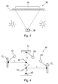
- a test apparatus for a conventional camera typically comprises a test rig 30, wherein a chart 32 is positioned in the field of view 34 of a camera 36 under test.
- the chart 32 typically comprises a plurality of stripes (e.g. black on a white background) located at different positions thereon (e.g. in the corners and center of the chart).
- the degree of focus of the camera is measured, for example, by assessing the apparent rate of change of light level between the dark and light areas of the chart as detected by the camera.
- the mount 16 when assessing a modulation transfer function of a conventional camera 10, the mount 16 is rotated about the lens 12 to determine the degree of sharpness detected by the camera 10 as a function of the rotational angle (or distance of the lens 12 from the chart).
- a prior art test apparatus for a no-focus camera comprises a plurality of charts positioned at different distances relative to the camera. The charts are individually and sequentially slid into the field of view of the camera. However, this is a cumbersome and time-consuming process, which is not amenable to quick decision-making regarding the desired location of the defocus of a no-focus camera.
- the preferred embodiment provides a mechanism for testing a camera with charts at various distances from the camera lens, wherein the preferred embodiment has a fixed test set up (i.e. with no moving parts).
- the preferred embodiment comprises a mounting system which positions a camera (which need not necessarily be fully assembled with all its components) so that it is facing a plurality of charts.
- the mounting system is further provided with a plurality of independently controllable illumination sources, which light each chart.
- the preferred embodiment comprises a one or more beamsplitters that direct the light reflected from the charts to the camera.
- the mounting system positions each chart at a fixed distance from the camera. More particularly, the charts are positioned at different distances (relative to each other) from the camera. A first chart is positioned closer to the camera than the camera's design focus distance. A second chart is spaced from the camera by its design focus distance; and a third chart is spaced from the camera at a distance larger than its design focus distance.
- the preferred embodiment comprises a control system, which enables a particular chart to be selected for viewing by the camera. More particularly, the choice of viewed chart is enabled by independently switching on/off the light sources, wherein the beamsplitters permit only the illuminated chart to be seen by the camera.
- the focus or image sharpness of the camera may be determined with any of several available methods (e.g. modulation transfer function (MTF), contrast transfer function (CTF), point spread function (PSF) etc.)
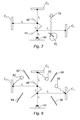
- an example of the preferred embodiment comprises a mounting system 40, which is configured to house a camera 42 under test.
- the mounting system 40 further comprises three charts C 1 , C 2 and C 3 and first and second beamsplitters 44, 46.
- the beamsplitters may be spectrally neutral, and may have varying transmission/reception characteristics to maintain scene luminance for each chart.
- the beamsplitters 44 and 46 are disposed at angles to each other, and the first beamsplitter 44 is disposed more proximal to the camera 42 than the second beamsplitter 46.
- the mounting system 40 comprises three lamps 48, 50 and 52.
- the lamps are arranged so that light from lamp 48 falls on chart C 1 , light from lamp 50 falls on chart C 2 and light from lamp 52 falls on chart C 3 .
- other implementations of the preferred embodiment may include a mechanism wherein each lamp is of a different brightness to maintain scene luminance for each chart.
- the positions of the charts C 1 -C 3 and/or beamsplitters 44, 46 with respect to the camera 42 under test may be independently set or adjusted by an adjusting mechanism, shown generally in Figure 5 as adjusting mechanism 51.
- the adjusting mechanism may be operatively connected to one or more of the charts C 1 -C 3 and/or to one or more of the beamsplitters 44, 46.
- the adjusting mechanism may comprise any suitable actuators and mechanical connections as are well known to a person skilled in the art. It is to be appreciated that the adjusting mechanism may be used to position the charts C 1 - C3 and/or beamsplitters 44, 46 to a desired configuration, which can then remain fixed during a method of testing the focus of an optical component.
- the lamps 48-52 may be independently controlled by a controlling system so that the lamps 48-52 may be independently switched on or off.
- a controlling system 60 is shown generally in Figure 6 , and in a preferred embodiment comprises a control connection to each of the lamps. More particularly, the lighting may be quickly switched between each chart C 1 -C 3 in turn.
- a camera focus testing apparatus may be provided that comprises both the controlling system 60 shown in Figure 6 and the adjusting mechanism 51 shown in Figure 5 .
- FIG. 7 Another implementation is shown in Figure 7 .
- a single lamp 70 may be used with a rotatable mirror 72 (or other light directing mechanism) whose rotation is controllable to shine light from the lamp on the different charts C 1 -C 3 .
- This approach may be useful in a low-power application. While it is recognized that it introduces a moving part (i.e. the mirror 72) into the apparatus, nonetheless, it is still considerably less cumbersome and time consuming than the above-mentioned prior art approach.
- the camera 42 under test may see any one of the charts C 1 -C 3 at the above-mentioned viewing distances and the charts can be backlit or frontlit depending on their construction (opaque or translucent types).
- the beamsplitters 44, 46 effectively restrict the light reaching the camera 42, so that the camera 42 is only permitted to see one illuminated chart.
- the lengths D 1 -D 3 (of the light paths from the charts C 1 -C 3 to the camera 42) represent three differing image distances, which could be 'less than design nominal', 'design nominal', and 'greater than design nominal'.
- design nominal refers in general to a predetermined intended value of a characteristic of a component.
- a component may be manufactured with the intention of possessing specific dimensions, or physical characteristics such as a permittivity or a density of a specific value.
- the term "design nominal” can sometimes be used as a parameter by which the performance of different components can be compared.
- a "design nominal” can be a focal length. That is, a lens will be manufactured to a specification that is intended to produce a specific desired focal length. Lenses can be chosen for specific applications based on their focal length (and/or on the basis of other characteristic values). The manufacturing process may however be flawed and the specific desired focal length may not be achieved in all cases. The actual focal length can then be compared to the design nominal focal length in a test procedure that verifies the properties of the lens.
- a camera For example, if a camera is intended to focus at 50cm, and achieves peak MTF at 25cm, it can be said to focus closer than design nominal. However, it will be realized that the light path lengths could be set at other distances.
- the preferred embodiment provides a cheap and fast way of determining where a best focus position is relative to an 'as built' focus position.
- the lens is built with an error in best focus position from its design optimum, and the degree of error (as built) can be determined from the design intent.
- Baffles may be provided to ensure minimal light spillage from the illuminated chart and the non-illuminated charts. These are shown as baffles 80, 82, 84 and 86 in Figure 8 . It will be appreciated that more of fewer baffles may be provided; and that the baffles can be provided with any of the embodiments illustrated in Figures 4 to 9 , or variations thereof.
- An image distance correction lens may be fixed in front of the camera to scale large image distances to a more compact arrangement. This is shown in Figure 9 as image correction lens 90. It will be appreciated that the image correction lens can be provided with any of the embodiments illustrated in Figures 4 to 9 , or variations thereof.
- FIG. 10 An alternative embodiment camera focus testing apparatus is shown in Figure 10 .
- a first test pattern display 100 and a second test pattern display 102 are provided.
- the test pattern displays may take the form of charts, as in the other example embodiments discussed above.
- the two displays 100, 102 are provided in an overlapping arrangement along an optical path 104 of a component under test 106.
- the first display 100 comprises a portion 108 that is at least partially transparent. This allows the pattern on the second display 102 to be imaged by the optical component under test 106, as light is permitted to pass from through the portion 108. The light reflected from the displays can be considered as being "directed" towards the optical component under test 106 by virtue of the arrangement.
- the first display 100 comprises a portion 110 that is the area under test
- the second display 102 comprises a portion 112 that is a second area under test. Printing of charts can be restricted to these areas 110, 112 only if required.
- the portion 108 of the first display 80 that is at least partially transparent may in a preferred embodiment comprise an aperture.
- test pattern displays can be provided if desired. At least each test display that is between the optical component under test and the most distant test display comprise various light transmissive portions, so that different test areas on each test display can be imaged by the optical component under test.
- test pattern displays in a fixed arrangement in the field of view of the optical component under test provides a compact structure that enables rapid determination of whether the optical component is short focused, long focused, or of bad quality. Neither the test pattern displays nor the optical component under test need to be moved during a method of testing the focus of the optical component.
- the set up of Figure 8 is also useful for testing a lens that has two focus positions.
- the test displays can be placed at the relevant design nominal focal planes of each focus position.
Landscapes
- Chemical & Material Sciences (AREA)
- Analytical Chemistry (AREA)
- Physics & Mathematics (AREA)
- General Physics & Mathematics (AREA)
- Automatic Focus Adjustment (AREA)
- Studio Devices (AREA)
Applications Claiming Priority (1)
| Application Number | Priority Date | Filing Date | Title |
|---|---|---|---|
| GBGB0821503.0A GB0821503D0 (en) | 2008-11-25 | 2008-11-25 | Optical component focus testing apparatus and method |
Publications (1)
| Publication Number | Publication Date |
|---|---|
| EP2189778A2 true EP2189778A2 (de) | 2010-05-26 |
Family
ID=40230781
Family Applications (1)
| Application Number | Title | Priority Date | Filing Date |
|---|---|---|---|
| EP09173232A Withdrawn EP2189778A2 (de) | 2008-11-25 | 2009-10-16 | Vorrichtung und Verfahren zur Fokusprüfung einer optischen Komponente |
Country Status (3)
| Country | Link |
|---|---|
| US (1) | US8456623B2 (de) |
| EP (1) | EP2189778A2 (de) |
| GB (1) | GB0821503D0 (de) |
Cited By (1)
| Publication number | Priority date | Publication date | Assignee | Title |
|---|---|---|---|---|
| CN113670579A (zh) * | 2020-05-13 | 2021-11-19 | 三赢科技(深圳)有限公司 | 多距离测试装置 |
Families Citing this family (3)
| Publication number | Priority date | Publication date | Assignee | Title |
|---|---|---|---|---|
| US20130021448A1 (en) * | 2011-02-24 | 2013-01-24 | Multiple Interocular 3-D, L.L.C. | Stereoscopic three-dimensional camera rigs |
| JP6267535B2 (ja) * | 2014-02-18 | 2018-01-24 | 日本放送協会 | 色収差測定システム |
| US11798447B1 (en) | 2022-07-29 | 2023-10-24 | Zoom Video Communications, Inc. | Illumination testing for shared device displays |
Family Cites Families (7)
| Publication number | Priority date | Publication date | Assignee | Title |
|---|---|---|---|---|
| US3904294A (en) * | 1973-12-28 | 1975-09-09 | Polaroid Corp | Automatic lens testing apparatus |
| US5664243A (en) * | 1995-06-08 | 1997-09-02 | Minolta Co., Ltd. | Camera |
| EP1687604A1 (de) | 2003-11-14 | 2006-08-09 | Koninklijke Philips Electronics N.V. | Verfahren und vorrichtung zur bestimmung der fokussierung eines abbildungssystems |
| JP2005191387A (ja) | 2003-12-26 | 2005-07-14 | Fujitsu Ltd | 撮像素子試験方法及び装置 |
| EP1628123A1 (de) | 2004-08-17 | 2006-02-22 | Dialog Semiconductor GmbH | Prüfung miniaturisierten Kameras mit optischen oder/und elektronischen Zoomfunktionen |
| US7598996B2 (en) | 2004-11-16 | 2009-10-06 | Aptina Imaging Corporation | System and method for focusing a digital camera |
| GB2426813A (en) | 2005-06-02 | 2006-12-06 | Hi Key Ltd | A method and apparatus for testing the focus, alignment and field of view angle of a lens of a camera |
-
2008
- 2008-11-25 GB GBGB0821503.0A patent/GB0821503D0/en not_active Ceased
-
2009
- 2009-10-16 EP EP09173232A patent/EP2189778A2/de not_active Withdrawn
- 2009-10-22 US US12/604,253 patent/US8456623B2/en not_active Expired - Fee Related
Cited By (1)
| Publication number | Priority date | Publication date | Assignee | Title |
|---|---|---|---|---|
| CN113670579A (zh) * | 2020-05-13 | 2021-11-19 | 三赢科技(深圳)有限公司 | 多距离测试装置 |
Also Published As
| Publication number | Publication date |
|---|---|
| US20100188653A1 (en) | 2010-07-29 |
| US8456623B2 (en) | 2013-06-04 |
| GB0821503D0 (en) | 2008-12-31 |
Similar Documents
| Publication | Publication Date | Title |
|---|---|---|
| JP5404122B2 (ja) | 焦点位置調整装置およびカメラ | |
| KR100924115B1 (ko) | 카메라 모듈 검사 장치 및 방법 | |
| CN101063799A (zh) | 图像投影装置 | |
| US7403229B2 (en) | Testing of miniaturized digital camera modules with electrical and/or optical zoom functions | |
| US8456623B2 (en) | Optical component focus testing apparatus and method | |
| US20020159143A1 (en) | Microscope episcopic illumination device and microscope therewith | |
| JP2014137482A (ja) | 撮影装置および撮影用照明装置 | |
| US20130286396A1 (en) | Inspection device | |
| US20090202148A1 (en) | Image Capturing System and Method for the Analysis of Image Data | |
| JP2011069893A (ja) | 照明装置およびカメラシステム | |
| TWI458965B (zh) | 用於影像資料之分析的影像擷取系統及方法 | |
| US7437065B2 (en) | Imaging apparatus | |
| US8079723B2 (en) | Adjustable lens with self-illuminated scale | |
| CN1690833A (zh) | 数码相机的自动对焦方法 | |
| CN119087655A (zh) | 用于高精密检测的光学系统和装置 | |
| US20100220292A1 (en) | Vision measuring system and assistant focusing system thereof | |
| JPWO2018186469A1 (ja) | 眼底撮影装置 | |
| US7321725B2 (en) | Light-amount control device for photographing | |
| KR20190115712A (ko) | 소도체 등심 영상 획득기 | |
| JP4546180B2 (ja) | 立体物イメージスキャナ | |
| KR101584455B1 (ko) | 부품의 내부를 촬영하는 촬영 모듈 및 이를 이용한 촬영 시스템 | |
| JP2007127704A (ja) | レンズシステム | |
| JP4871403B2 (ja) | 立体物イメージスキャナ | |
| JP2021086121A (ja) | 撮像装置及び表面検査装置 | |
| US20260029106A1 (en) | Near-light illumination |
Legal Events
| Date | Code | Title | Description |
|---|---|---|---|
| PUAI | Public reference made under article 153(3) epc to a published international application that has entered the european phase |
Free format text: ORIGINAL CODE: 0009012 |
|
| AK | Designated contracting states |
Kind code of ref document: A2 Designated state(s): AT BE BG CH CY CZ DE DK EE ES FI FR GB GR HR HU IE IS IT LI LT LU LV MC MK MT NL NO PL PT RO SE SI SK SM TR |
|
| STAA | Information on the status of an ep patent application or granted ep patent |
Free format text: STATUS: THE APPLICATION IS DEEMED TO BE WITHDRAWN |
|
| 18D | Application deemed to be withdrawn |
Effective date: 20150501 |