EP2189734A2 - Heater controller and method for operating a heater controller - Google Patents
Heater controller and method for operating a heater controller Download PDFInfo
- Publication number
- EP2189734A2 EP2189734A2 EP09176373A EP09176373A EP2189734A2 EP 2189734 A2 EP2189734 A2 EP 2189734A2 EP 09176373 A EP09176373 A EP 09176373A EP 09176373 A EP09176373 A EP 09176373A EP 2189734 A2 EP2189734 A2 EP 2189734A2
- Authority
- EP
- European Patent Office
- Prior art keywords
- switching element
- heater controller
- current
- switching
- state
- Prior art date
- Legal status (The legal status is an assumption and is not a legal conclusion. Google has not performed a legal analysis and makes no representation as to the accuracy of the status listed.)
- Granted
Links
- 238000000034 method Methods 0.000 title claims description 15
- 238000010438 heat treatment Methods 0.000 claims abstract description 139
- 238000002955 isolation Methods 0.000 claims description 25
- 230000009467 reduction Effects 0.000 claims description 6
- 230000004044 response Effects 0.000 claims description 6
- 230000008901 benefit Effects 0.000 description 28
- 230000006378 damage Effects 0.000 description 12
- 238000010586 diagram Methods 0.000 description 8
- 230000007257 malfunction Effects 0.000 description 8
- 238000005259 measurement Methods 0.000 description 7
- 238000013459 approach Methods 0.000 description 5
- 230000001276 controlling effect Effects 0.000 description 5
- 238000001514 detection method Methods 0.000 description 5
- 238000013021 overheating Methods 0.000 description 4
- 230000009471 action Effects 0.000 description 3
- 230000007547 defect Effects 0.000 description 3
- 238000012360 testing method Methods 0.000 description 3
- 238000004378 air conditioning Methods 0.000 description 2
- 238000002485 combustion reaction Methods 0.000 description 2
- 230000003750 conditioning effect Effects 0.000 description 2
- 230000002349 favourable effect Effects 0.000 description 2
- 230000007246 mechanism Effects 0.000 description 2
- 230000008569 process Effects 0.000 description 2
- 239000002918 waste heat Substances 0.000 description 2
- 238000006243 chemical reaction Methods 0.000 description 1
- 238000001816 cooling Methods 0.000 description 1
- 230000006866 deterioration Effects 0.000 description 1
- 230000000694 effects Effects 0.000 description 1
- 230000010354 integration Effects 0.000 description 1
- 239000000463 material Substances 0.000 description 1
- 238000012545 processing Methods 0.000 description 1
- 230000001105 regulatory effect Effects 0.000 description 1
- 230000008439 repair process Effects 0.000 description 1
- 230000000630 rising effect Effects 0.000 description 1
- 230000001131 transforming effect Effects 0.000 description 1
- 230000007704 transition Effects 0.000 description 1
- 238000010792 warming Methods 0.000 description 1
- 239000002699 waste material Substances 0.000 description 1
Images


Classifications
-
- B—PERFORMING OPERATIONS; TRANSPORTING
- B60—VEHICLES IN GENERAL
- B60H—ARRANGEMENTS OF HEATING, COOLING, VENTILATING OR OTHER AIR-TREATING DEVICES SPECIALLY ADAPTED FOR PASSENGER OR GOODS SPACES OF VEHICLES
- B60H1/00—Heating, cooling or ventilating [HVAC] devices
- B60H1/22—Heating, cooling or ventilating [HVAC] devices the heat being derived otherwise than from the propulsion plant
- B60H1/2215—Heating, cooling or ventilating [HVAC] devices the heat being derived otherwise than from the propulsion plant the heat being derived from electric heaters
- B60H1/2218—Heating, cooling or ventilating [HVAC] devices the heat being derived otherwise than from the propulsion plant the heat being derived from electric heaters controlling the operation of electric heaters
-
- H—ELECTRICITY
- H05—ELECTRIC TECHNIQUES NOT OTHERWISE PROVIDED FOR
- H05B—ELECTRIC HEATING; ELECTRIC LIGHT SOURCES NOT OTHERWISE PROVIDED FOR; CIRCUIT ARRANGEMENTS FOR ELECTRIC LIGHT SOURCES, IN GENERAL
- H05B1/00—Details of electric heating devices
- H05B1/02—Automatic switching arrangements specially adapted to apparatus ; Control of heating devices
- H05B1/0202—Switches
-
- B—PERFORMING OPERATIONS; TRANSPORTING
- B60—VEHICLES IN GENERAL
- B60H—ARRANGEMENTS OF HEATING, COOLING, VENTILATING OR OTHER AIR-TREATING DEVICES SPECIALLY ADAPTED FOR PASSENGER OR GOODS SPACES OF VEHICLES
- B60H1/00—Heating, cooling or ventilating [HVAC] devices
- B60H1/22—Heating, cooling or ventilating [HVAC] devices the heat being derived otherwise than from the propulsion plant
- B60H2001/2228—Heating, cooling or ventilating [HVAC] devices the heat being derived otherwise than from the propulsion plant controlling the operation of heaters
- B60H2001/2231—Heating, cooling or ventilating [HVAC] devices the heat being derived otherwise than from the propulsion plant controlling the operation of heaters for proper or safe operation of the heater
-
- B—PERFORMING OPERATIONS; TRANSPORTING
- B60—VEHICLES IN GENERAL
- B60H—ARRANGEMENTS OF HEATING, COOLING, VENTILATING OR OTHER AIR-TREATING DEVICES SPECIALLY ADAPTED FOR PASSENGER OR GOODS SPACES OF VEHICLES
- B60H1/00—Heating, cooling or ventilating [HVAC] devices
- B60H1/22—Heating, cooling or ventilating [HVAC] devices the heat being derived otherwise than from the propulsion plant
- B60H2001/2246—Heating, cooling or ventilating [HVAC] devices the heat being derived otherwise than from the propulsion plant obtaining information from a variable, e.g. by means of a sensor
- B60H2001/2256—Heating, cooling or ventilating [HVAC] devices the heat being derived otherwise than from the propulsion plant obtaining information from a variable, e.g. by means of a sensor related to the operation of the heater itself, e.g. flame detection or overheating
Definitions
- the present invention relates to a heater controller according to claim 1 as well as to a method of operating a heater controller according to claim 9.
- This separate heating element is mostly connected with the vehicle-battery (or an accumulator) which also provides the power for the electric motor of the propulsion system.
- the battery (or the accumulator) of such a car or vehicle with said hybrid motor or a single electric motor usually has to provide a high electric power such that the batteries usually have a high voltage output of, for example, more than 100V, especially about 300 V.
- a conventional vehicle battery is used (which just provides voltages about 12 to 24 V) the necessary high electric power for the electric motors of the hybrid cars requires a very high current which, in turn, results in a high energy loss due to an unintentional warming up of electric components handling these currents.
- the positioning of the switching elements in the high voltage side (also denoted as high side) of the heater has the disadvantage that for example due to cracks in the wafer material of the power electronic switches a short-circuit in such a switch can cause a complete damage of the switching element which, in turn, results in the above mentioned uninterruptable and continuous flow of current via the defect switching element through the heating element. This would result in a very quick discharge of the battery.
- the present invention provides a heater controller for supervising a heating element in a vehicle, the heater controller comprising the following features:
- the present invention provides a method for operating a heater controller, the method comprising the following steps:
- the present invention is based on the finding that a more secure switching-off of power can be accomplished by a control unit which is positioned between the heating element (respectively a contact thereof) and an output contact which is preferably connectible to a ground potential.
- This control unit can comprises a serial connection of a switching element and a current sensor which are both in contact with said control element. Furthermore, the control element is connected to the first switching element which is connected between a (high voltage) input contact and a heating element (respectively a contact thereof). If the first switching element is damaged such a that ,for example, a short-circuit results in a continuous current flowing through the heating element it is now possible to switch off the respective heating element by the second switching element of the control unit.
- the control element uses a signal of the current sensor indicating a current during the time interval in which the first switching element should be closed. As normally no current should flow in a time interval in which the first switching element is in an off-state it is clear that the first switching element is damaged if a current is detected in such a time interval.
- a comparison of the signals of the current sensor with the first control signal can be performed which controls the state in which the first switching element should be.
- the second control signal can be generated in order to bring the second switching element in an off-state.
- the present invention provides the advantage that a more secure and reliable heater controller can be created which has superior characteristics with respect to the state-of-the-art concerning a secure switching-off of the heating elements in order to prevent the power supply of the vehicle from being discharged unintentionally. Furthermore the positioning of the control unit in the low voltage side of the heater controller (i.e. after the heating element in a current flow) has the advantage that the second switching element can be configured for only switching low voltages, which on the one side opens the possibility of using inexpensive electronic elements and, on the other side, provides the chance for a very precise switching characteristic.
- the second switching element is implemented on a low voltage side of the heater controller the risk of a damage of said second switching element by high potentials of the power supply is furthermore reduced such that the security and reliability of the inventive heater controller is increased in comparison to the state-of-the-art heater controllers.
- the second switching element can be configured for switching between an on-state and an off-state, wherein the second switching element initially is in the on -state.
- the heater controller can be used normally again after a malfunction of the first switching element is repaired. This repair of the first switching element can for example be accomplished by a cooling down of the first switching element as the malfunction may just be a result of excessive heat. Compensation can then be done on the other stages.
- the second switching element is just a fuse the heater controller (at least the respective heating element stage) cannot be used anymore such that the heater controller itself has to be exchanged in order to remedy the malfunction which would be much more expensive.
- the second switching element can be configured for switching voltage signals.
- Such an embodiment of the present invention provides the advantage that inexpensive electronic components can be used in order to provide said secure and reliable characteristics of the heater controller in contrast to state-of-the-art heater controllers. Furthermore, a quick switching-off of current flowing through the first switching element in a malfunction-situation of the first switching element can be guaranteed as low voltage switching elements usually have a faster switching characteristic than high-voltage switching elements.
- the first switching element provides the advantage that a well-established power electronics component is used for switching the current through the heating elements such that the risk of suffering damage in the first switching element can be strongly reduced.
- the second switching element provides the advantage that also well-established components with quick switching characteristics are used such that in the case of a malfunction of the first switching element a prompt switching-off is guaranteed.
- the heater controller can comprise at least one heating element, especially a PTC heating element, which is connected between the first and second connection contact of the heating element connection port.
- PTC heating elements provides the advantage that these heating elements have a favorable characteristic in a case of a malfunction of the first switching element as in a short-circuit situations the resistance of these heating elements rises, which, in turn, results in a lower current flowing through said heating element in the case of de short-circuit in the first switching element while the second switching element is still in an on-state. If the second switching element now also fails to disconnect the heating element from the output contact the PTC heating element (due to its rising resistance characteristics) ensures a minimal waste of power such a that the power of vehicle battery can be longer preserved.
- the first switching element can be configured for detecting a short-circuit through the first switching element, wherein the first switching element can furthermore be configured for bringing the first switching element in an off-state if a short circuit is detected in the first switching element.
- the short-circuit detection in the first switching element is done in hardware such that it is extremely fast and does not depend on the state of the control element.
- a short-circuit in the first switching element normally results from a "fusing" of the electronic component used as first switching element such that a detection of such a fusing in an early stage enables the chance of timely bringing the first switching element in an off-state such that a permanent short-circuit of the first switching element can be prevented.
- the heater controller comprises a safety relay being connected between the serial connection and the output contact or being connected between the input contact and the first switching element.
- the safety relay can, for example, be a fuse or a mechanical relay opening a connection in response to excess heat or excess current.
- the heating element connection port has a third and a fourth connection contact, the third connection contact being connected to the input contact via the first switching element or a third switching element, the heater controller furthermore having a second serial connection comprising a fourth switching element and a second current sensor for providing a second current signal indicating a current through the second current sensor, the second serial connection being connected between the fourth contact of the heating element connection port and the output contact and wherein the control element being connected to the fourth switching element and the second current sensor, the control element being furthermore configured for providing the first control signal to the first switching element or for providing a third control signal to the third switching element to switch the third switching element in an on-state or in an off-state, the control element being furthermore configured for receiving the second current signal from the second current sensor and for providing a fourth control signal to the fourth switching element to disconnect an electrical connection between the fourth connection contact and the output contact in the case the second current signal indicates a current through the second current sensor while the first and/or the third switching element is in off-state.
- This embodiment of the present invention provides the advantage that at least two stages of heating elements can be separately controlled in a secure and reliable way such a that each of these heating element stages can separately be disconnected from the input contact respectively output contact of the heater controller.
- the positioning of the controller unit having the second switching element as well as the fourth switching element with the respective current sensors in the low-side provides the advantage of a precise and timely switching characteristic as well as the use of inexpensive electronic components which do not have to stand high potentials.
- the control element can be configured for switching the second switching element in an off-state if the second current signal indicates a current through the second current sensor in a time interval in which the third switching element is in an off-state and/or wherein the control element is configured for switching the fourth switching element in an off-state if the current signal indicates a current through the current sensor while the first switching element is in an off-state.
- This switching-off of more than just the respective heating element stage having the damaged switching element provides the advantage that the current load of the heating element stages which function correctly does not exceed a specific level.
- This high current load in the case of a malfunction of one heating element stage might be a result as the current which normally would pass the heating element stage which is damaged now reallocates on the error-free heating element stages such that an excess current load in the these error-free heating element stages might occur if an electronic contact in the these heating element stages is not disconnected.
- the controller element can be configured for controlling the first and third switching elements such that the time intervals of the on-states of the first and third switching elements are phase shifted.
- the controller element can be configured for controlling the first and third switching elements such that the time intervals of the on-states of the first and third switching elements are phase shifted.
- the heater controller may comprise a galvanic isolation element which is arranged to galvanically isolate the control element on a first side from the first switching element and the serial connection on a second side.
- a galvanic isolation element which is arranged to galvanically isolate the control element on a first side from the first switching element and the serial connection on a second side.
- the heater controller may comprise a galvanic isolation element which is arranged to galvanically isolate the control element, the first switching element and the serial connection on a first side from a signal bus on a second side, wherein the signal bus is configured to provide control signals to the control element in order to control operations of the control element.
- a galvanic isolation element which is arranged to galvanically isolate the control element, the first switching element and the serial connection on a first side from a signal bus on a second side, wherein the signal bus is configured to provide control signals to the control element in order to control operations of the control element.
- a voltage reduction element can be coupled between the input contact and the first switching element or the first driver element, wherein the voltage reduction element is configured for reducing the voltage between the input contact and the output contact and for providing a reduced voltage to the first switching element or the first drive element.
- a voltage reduction element provides the advantage that a low-level voltage which is mostly needed for properly operating the high-side switch or switches can be directly provided from the voltage between the input contact and the output contact.
- it is not necessary to provide a low-level voltage path through the galvanic isolation element 199 which, in turn, improves the protection of a the components galvanically separated from the input and output contacts.
- control element can be configured to compare the signal received from the current sensor in an off-state of the first switching element with an expected signal from the current sensor when the first switching element is in off-state and wherein the control element is furthermore configured for outputting an error signal, if the received signal from the current sensor departs from the expected signal by more than a predefined value.
- a failure test can thus be based on a comparison of the received signals with a reference value which may be either determined during a drafting process of the heater controller circuit or by reference measurements carried out under laboratory conditions.
- a test for failure can be accomplished for example before the first high-side switch or high-side switching element is turned into an on-state. This, in turn, avoids damage to components of the heater controller as in the on-state usually high currents flow through the different heater stages which may cause an overheating of different areas of the heater controller if one of the heater stages is damaged.
- control element may be configured to compare the signal received from the current sensor in an on-state of the first switching element with an expected signal from the current sensor when the first switching element is in on-state and wherein the control element is furthermore configured for outputting an error signal, if the received signal from the current sensor departs from the expected signal by more than a predefined value.
- failure test can also be based on a comparison of the received signals with a reference value which may be either determined during the drafting process of the heater controller circuit or by reference measurements carried out under laboratory conditions.
- FIG. 1 shows a block diagram of a heater controller 100 as an embodiment of the present invention.
- the heater controller 100 comprises an input contact 105 and an output contact 110 wherein the input contact 105 can be connected to a positive (or negative) contact of a vehicle battery whereas the output contact 110 can be contacted with a ground potential.
- the vehicle battery will provide high voltages of for example 300 V such that a voltage of, for example, 300 V is provided between the input contact 105 and the output contact 110.
- the heater controller 100 comprises a first heating element stage (or level) 115 and a second heating element stage (or level) 120 which are connected in parallel between the input contact 105 and the output contact 110.
- first and second heating element stages 115 and 120 are just chosen for exemplary purposes such that the heater controller 100 can also comprise further heating element stages (which for example also comprise analog elements as the first and second heating element stages) which are, however, not shown in Figure 1 for reasons of simplicity.
- the first heating element stage 115 comprises a first switching element 125 which may be a power electronic element and which is connected between the input contact 105 and a first contact 130 of a heating element connection port. Furthermore, the first heating element stage 115 comprises a second contact 135 of the heating element connection port which is connected via a serial connection 140 to the output contact 110, the serial connection 140 comprising a second switching element 145 and a first current sensor 150. Between the first contact 130 of the heating element connection port and the second contact 135 of the heating element connection port a PTC heater resistor 153 may be contacted which, in use of the heater controller 100, heats at least a portion of air for conditioning the passenger cabin.
- the PTC heater resistor 153 (as heating element) needs not necessarily be already contacted with the heating element connection port when the heater controller 100 is delivered to the customer. Additionally, the heating element 153 may also be located at an external position from the heater controller 100 such that the heater controller 100 as shown in Figure 1 can be positioned at any place in the vehicle.
- the first switching element 125 which also can be denominated as "high-side switch” (due to the connection with the high potential of the power supply via the input contact 105), is connected to a first driver 155 which, in turn, receives a first control signal PWM1 from a control element 160.
- the control element 160 may be an electronic component like a digital signal processor, a microprocessor, an application specific integrated circuit or the like which is capable of processing signals and outputting the control signals to the switching elements.
- the first driver 155 may also transmit an error signal F1 to the control element 160 in the case an error in the first switching element 125 is detected.
- the first current sensor 150 of the serial connection 140 may also transmit a (first) current signal 11 to the control element 160 whereas the second switching element 145 can receive a second control signal C1 from the control element 160.
- the second heating element stage 120 can be built similarly to the first heating element stage 115.
- the second heating element stage may comprise a third switching element 165 which may also be a power electronic element (like an IGBT, a thyristor, a triac or a diac) and which is connected between the input contact 105 and a third contact 170 of the heating element connection port.
- the second heating element stage 120 comprises a fourth contact 175 of the heating element connection port which is connected via a second serial connection 180 to the output contact 110, the second serial connection 180 comprising a fourth switching element 185 and a second current sensor 190.
- a second PTC heater resistor 193 may be contacted which, in use of the heater controller 100, again heats at least a portion of air for conditioning the passenger cabin of the vehicle.
- the second PTC heater resistor 193 (as second heating element) also needs not necessarily to be already contacted with the heating element connection port when the heater controller 100 is delivered to the customer.
- the second heating element 193 may also be located at an external position from the heater controller 100 such that the heater controller 100, as shown in Figure 1 , can be positioned at any place in the vehicle.
- the third switching element 165 which can be denominated as "second high-side switch" (again due to the connection with the high potential from the power supply via the input contact 105), is connected to a second driver 195 which, in turn, receives a second control signal PWM2 from the control element 160.
- the second driver 195 may also transmit an error-signal F2 to the control element 160 in the case an error in the second switching element is detected.
- the second current sensor 190 of the second serial connection 180 may also transmit a (second) current signal 12 to the control element 160 whereas the fourth switching element 185 may receive a fourth control signal C2 from the control circuit 160.
- the control element 160 comprises a galvanic isolation 199 such a that on one side of the galvanic isolation 199 it may receive or send control signals (for example via a Bus "Control") or be connected to a low voltage (for example 12 V) and a ground potential and on the other side of the galvanic isolation 199 it may receive or send a the above-mentioned signals to the further components of the heater controller 100.
- a galvanic isolation 199 such a that on one side of the galvanic isolation 199 it may receive or send control signals (for example via a Bus "Control") or be connected to a low voltage (for example 12 V) and a ground potential and on the other side of the galvanic isolation 199 it may receive or send a the above-mentioned signals to the further components of the heater controller 100.
- the heater controller 100 may function as described in the following paragraphs.
- the control element 160 can send the first control signal PWM1 to the first switching element 125 or the first switching element driver 155.
- the first switching element 125 may be a high-side switch and the first switching element driver 155 may be a high-side driver for transforming, for example, a voltage of a signal of the control element 160 to a voltage which is configured for bringing the first switching element 125 in an on-state or in an off-state.
- the first control signal PWM1 may be a pulse-width-modulated (PWM) signal having a first and a second signal level, wherein the first signal level (which may be for example a ground potential) indicates the first switching element 125 or the first switching element driver 155 to switch the first switching element 125 in an off-state and wherein the second signal level (which may be for example a voltage of 5 or 12 V) indicates the first switching element 125 or the first switching element driver 155 to switch the first switching element 125 in an on-state.
- PWM pulse-width-modulated
- the first switching element 125 is switched in the off-state during a first period in which the first control signal PWM1 has the first signal level whereas the first switching element 125 is switched in the on-state during a second time interval in which the first control signal PWM1 has the second signal level. Therefore, a heating element 153, which may be connected between the first and second heating connection contacts 130 and 135 may be supplied with a voltage from a the input contact 105 during the second period in which the first control signal PWM1 has the second signal level. Using this pulse-width modulated first control signal PWM1 the energy transferred from the input contact 105 to the heating element 153 can be easily regulated by changing the time intervals of the first and second signal levels of the first control signal PWM1.
- the heater controller 100 comprises said serial connection 140 which itself comprises the second switching element 145 (which is a low-side switch) and the first current sensor 150, the second switching element 145 and the first current sensor 150 being both connected to the control element 160.
- the serial connection 140 now provides the strong advantages of the present invention as it enables the control element 160 to supervise the correct function of the first switching element 125.
- the control element 160 is able to determine whether there is actually no current flowing through the serial connection 140 during the time interval in which the first control signal PWM1 has the first signal level.
- the control element 160 may be configured for sending a second control signal C1 to the first low-side switch 145 in order to switch the first low-side switch 145 (which is initially or normally during operation of the heater controller 100 in on-state) in an off-state.
- a reliable disconnection of the heating element 153 from the power supply can be performed even if the first high-side switch 125 is a damaged and is in a permanent short-circuit on-state.
- the (first) serial connection 140 is positioned in the low side of the heater controller 100, i.e. between the second heating connection port contact 135 and the output contact 110 which may be contacted to the ground potential.
- This provides the advantage that inexpensive and precise switching elements can be used which do not need to stand high voltages like the first high-side switch 125.
- the first serial connection 140 may easily be positioned at a different place on a circuit board of the heater controller 100. Additionally using the first serial connection 140 in the low side provides the advantage that an easy measurement of the current can be performed as there is no need to use a current monitor or to measure two voltages across the shunt (with a reference being always the ground potential).
- the high-side driver 155 may include a short-circuit detection mechanism which deactivates the high-side-switch in case of short-circuit current. This is done in hardware so it is extremely fast and does not depend on the state of the control circuit. This detection of a short-circuit current and a timely switching-off of the first high-side switch 125 may then prevent a fusing of internal layers of the electronic element forming the first high-side switch 125 such that a heating-up of elements in the vicinity of the first high-side switch 125 and a possible destruction of these elements can effectively be prevented.
- the first high-side driver 155 may send an error signal F1 to the control element 160 in order to communicate to the control element 160 that the first high-side switch 125 is damaged and that the (first) heating element 153 cannot be used anymore until the first high-side switch 125 is replaced.
- a second heating element stage 120 (also denoted as heating element level) may be used, which may be contacted in parallel to the first heating element stage 115 between the input contact 105 and the output contact 110.
- the configuration of elements of the second heating element stage 120 may be the same as the configuration of elements of the first heating element stage 115 such that the controlling of the second heating element stage 120 by the control element 160 may be performed in an analog way as the controlling of the first heating element stage 115.
- the control element 160 may send a pulse-width modulated third control signal PWM2 to the third switching element 165 respectively the second switching element driver 195 in order to bring the second high-side switch 165 in an off-state (in a time interval in which the third control signal has a first signal level) or in an on-state (in a time interval in which a the third control signal has a second signal level).
- the second current sensor 190 of the second serial connection 180 may transmit the second current signal 12 to the control element 160 which, in the case a current in the second serial connection 180 is detected during the time interval in which the third control signal PWM2 has the first signal level, may output a fourth control signal C2 to the fourth switching element 185 (respectively the second low-side switch) in order to bring the second low-side switch 185 into an off-state.
- the second low-side switch 185 is initially and in a normal operation of the heater controller 100 in an on-state the provision of the second serial connection 180 also enables an inexpensive and precise supervision of the correct function of the second high-side switch 165.
- the second high side switch 165 may also be supervised on the short-circuit fault by the second high-side driver 195 which may be able to bring the second high-side switch 165 in an off-state if such a fusing of the second high-side switch 165 is detected by the second high-side driver 195.
- the second high-side driver 195 may then communicate a fault signal F2 to the control element 160 in order to inform the control element 160 that a correct switching of power through the second heating element 193 is not guaranteed anymore until the second high-side switch 165 is replaced.
- the second high-side driver may include a short-circuit detection mechanism which deactivates the second high-side switch in case of a short-circuit current. This may be done in hardware so it is extremely fast and does not depend on the state of the control circuit.
- the present invention is not limited to using it just to heating element stage this 115 or 120 as shown in Figure 1 . Rather it is possible to use further (i.e. a third, a fourth, a fifth,. . . ) heating element stages which preferably have the same configuration of elements as the first heating element stage 115 or the second heating element stage 120.
- heating elements 153 or 193 as shown in Figure 1 may not be part of the heater controller 100 but they may be connected to the contacts of the first heating element connection port 130 respectively 135 or the contacts of the second heating element connection port 170 respectively 175 while mounting the heater controller 100 into the car or vehicle.
- the inventive approach according to the embodiment shown in Figure 1 provides a solution to the above mentioned problem in that the high-side switch is driving the (PTC-) stages with a certain duty cycle wherein this specific duty cycle is requested through the control interface.
- the low-side-switch is constantly closed, such that the high-side switch is controlling the current flow over the (PTC-) stages.
- the current-check module detects a malfunction of the high-side switch (which may result in a constant current flow even though the PWM-signal forces the first switching element to an off-state) the low-side switch can disconnect the current flow over the specific (PTC-) stage.
- control element 160 may be configured for bringing the first low-side switch 145 as well as the second low-side switch 185 in an off-state if, for example, the first current sensor 150 detects a current through the serial connection 140 although the first high-side switch 125 should be in an off-state or if the second current sensor 190 indicates a current in the second serial connection 180 although the second high-side switch 165 should be in an off-state.
- Such an embodiment of the present invention provides the advantage that in the case of one high-side switch failing no current flows through the heating elements of the respective stages. This, in turn, provides an additional security as an at least partly damaged heater controller 100 is only used in little extent.
- control element 160 may be configured for switching the high-sided switches into an off-state which are located adjacent to the damaged switch on the circuit board of the heater controller 100.
- the control element 160 may be configured for switching the high-sided switches into an off-state which are located adjacent to the damaged switch on the circuit board of the heater controller 100.
- the safety relay may be integrated on a hot lead and/or on return lead for redundancy protection.
- said safety relay may also open or close an electric connection of the heating elements of the individual heating element stages to the power supply such that an overheating of the heater controller 100 may be effectively prevented.
- the safety relay can be implemented for delivering the current flow to all levels or stages of heating elements instead of using just one high-sided switch per level.
- the control element 160 should take into account the signals of the first current sensor 150 as well as second current sensor 190 in order to determine the second and fourth control signal to the first low-side switch 145 and the second low-side switch 185.
- the advantage of the present invention in all its embodiments can be seen in the fact that it provides a very safe high-side switch solution which disconnects completely the voltage from the load if no heating is requested.
- the specific heating element level can be reliably disconnected from the power supply (using the low power switch respectively low-side switch) and a compensation can be done.
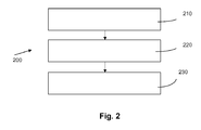
- the present invention provides a method 200 for operating a heater controller, a flow diagram of the method being depicted in Fig. 2 .
- the method 200 uses a heater controller as described above and comprises a first step of switching 210 a first switching element in an on-state or an off-state in order to intermittently provide power from an input contact of the heater controller to a first connection contact of a heating element connection port of the heater controller, the first switching element being configured for switching power signals.
- the method 200 comprises a step of measuring 220 a current in a serial connection and providing a current signal in response of the measured current, wherein the serial connection comprises a current sensor and a second switching element and wherein the serial connection is connected between a second connection contact of the heating element connection port and an output contact of the heater controller.
- the method 200 comprises a step for switching 230 the second switching element in an off-state if the current signal indicates a current in the current sensor during a period in which the first switching element is controlled to be in off-state.
- the high-voltage PTC electronic architecture comprises a separate galvanic isolation element 199 as shown in the block diagram according to Figures 3 or 4 .
- the galvanic isolation element 199 acts as an electrical disconnection to electrically or galvanically isolate two sides from each other. The effect of this protection of the control circuit by the galvanic isolation element depends on its integration in the electronic circuit.
- the galvanic isolation element 199 is implemented in the heater system to protect the electronic area from the power area if a failure occurs in the power area.
- This failure can be for example a shortage or the like such that the high voltage between the power contacts 105 and 110 can break through from the power switch elements 125, 145, 150, 155, 165, 185, 190 or 195 into the control circuit 160.
- the galvanic isolation element 199 is connected such that the control signals 300 between the control circuit 160 and the power switch elements 125, 145, 150, 155, 165, 185, 190 or 195 (as for example the signals PWM1, F 1, PWM2, F2, C1, C2, I1 or I2) have to pass of the galvanic isolation element 199.
- the galvanic isolation element 199 is implemented between the control circuit area and the high voltage circuit area, to protect not only the connected ECU modules through the low voltage signal interface but also to protect the control circuit against a high voltage circuit failure.
- the galvanic isolation element 199 between the mentioned power switch elements 125, 145, 150, 155, 165, 185, 190 or 195 and the control circuit 160 the danger of damage of the elements of the control circuit 160 or the elements of an interface 310 having signal levels in the range of for example 0 to 12 V can be effectively prevented.
- Such elements may be for example the driver elements 155 or 195.
- the low voltage of for example 12 V is needed in these elements to activate the first power switch 125 or the second power switch 165 in response to respectively received signals PWM1 or PWM2.
- the respective low-voltage consuming elements of the power switch circuit 125, 145, 150, 155, 165, 185, 190 and 195 can be provided by reducing the voltage between the input pins 105 and 110 to the desired voltage level via a voltage reduction element 315.
- a voltage reduction element 315 it is also possible to provide the respective low-voltage consuming elements in the power switch circuit with a voltage directly from the interface 310 via a separate line 320 which the then, of course, has also be routed through the galvanic isolation element 199.
- the galvanic isolation element 199 may be, for example, an optocoupler or an isolating transformer.
- FIG. 4 shows a block diagram of another embodiment present invention in which the galvanic isolation element 199 is located between the low-voltage interface 310 and the control circuit 160.Thus the galvanic isolation element 199 is implemented to protect mainly the low voltage signal interface 310 so that other ECU modules connected via the low voltage signal interface 310 will not be affected by high voltage failure within the heater controller.
- galvanic isolation element 199 provides the advantage that a very safe isolation between low and high voltage circuit can be realized.
- the above described circuit arrangement comprising the galvanic isolation element 199 permits to protect the control circuit 160 as the specific failing PTC levels can be securely disconnected and compensation can be done on other PTC levels.
- the present invention provides another embodiment in which a safety measurement is done after start-up, to protect the ECU module itself and other connected ECU modules.
- a safety measurement is done after start-up, to protect the ECU module itself and other connected ECU modules.
- the leakage current through one single and/or each PTC string can be individually measured and compared to a corresponding previously recorded "PTC-LeakageCurrent-Temp" Profile.
- a mismatch in between the measured currents and the corresponding "PTC-LeakageCurrent-Temp" Profile being detected, there is a real problem (e.g. a shortage, a damage or the like ...) detected within the PTC heater and proper action is needed.
- This action can be seen in for example a switching off of a single damaged PTC heater level or in switching off of the complete PTC heater, i.e. switching off all PTC heater elements.
- the currents can be measured through one single and/or each PTC string and the measured values are compared to a previously recorded corresponding "PTC-Current-Temp"-Profile. Should a mismatch in between the measured currents and the corresponding "PTC-Current-Temp"-Profile being detected, there is also a real problem (e.g. a shortage, a damage or the like ...) detected within the PTC heater and proper action is needed.
- a possible supplementary measurement can be accomplished to prevent the electronic elements and the PTC elements from possible failure in the air conditioning system. For this it is necessary to measure the isolation resistance between a supplementary wire and/or a cover at nominal high voltage and compare it to a reference value. Furthermore, a possible supplementary measurement which can be done by switching-on the control circuit 160 is to generate a heating profile (for example low values on the command) and verify if the power heating is different than the awaited nominal value.
- a heating profile for example low values on the command
Abstract
Description
- The present invention relates to a heater controller according to
claim 1 as well as to a method of operating a heater controller according toclaim 9. - Conventional cars mostly use a combustion motor for propulsion which has the favorable effect that the waste heat of the combustion engine can be used for heating the interior of a passenger cabin of the car or vehicle. However, in the near future more and more cars or vehicles will be powered by hybrid motors or exclusively by electric motors. As electric motors or hybrid motors do not provide large amounts of waste heat there is a problem, especially in winters, to heat the passenger cabin sufficiently so as to provide a comfortable temperature for the passengers in the cabin of the vehicle. In order to provide such a comfortable heat a separate heating element has to be used.
- This separate heating element is mostly connected with the vehicle-battery (or an accumulator) which also provides the power for the electric motor of the propulsion system. As the battery (or the accumulator) of such a car or vehicle with said hybrid motor or a single electric motor usually has to provide a high electric power such that the batteries usually have a high voltage output of, for example, more than 100V, especially about 300 V. If, in contrast, a conventional vehicle battery is used (which just provides voltages about 12 to 24 V) the necessary high electric power for the electric motors of the hybrid cars requires a very high current which, in turn, results in a high energy loss due to an unintentional warming up of electric components handling these currents.
- However, there is a problem in controlling the heating elements due to the fact that these heating elements are supplied with power of high voltage networks which are implemented in new generations of electrical vehicles. This problem can be seen in a connection of the high voltage power switch which is directly connected to the battery (providing said high voltage) wherein the switching strategy is given by the control circuit of the electronics which normally is configured for handling low voltages. Therefore the switching elements have to comprise power electronic components in order to adequately switch the power from the battery. However, in case of failure of these switching components, the heating element stages (sometimes also denoted as heating levels) can continue to heat air without the possibility to interrupt the current from the power supply. The result of a failure of the switching element will be a continuous drain of current of the heating element such that it has to be replaced as otherwise the battery of the vehicle will be unloaded very quickly by the damaged switching element and the heating element.
- According to state-of-the-art solutions which are published for example in
EP1630013 orEP1630923 a supervision of the correct function of the switching element is performed wherein the switching element is connected between the heating elements and a high-voltage power supply contact. The positioning of the switching elements on the high voltage side of the heating elements has the advantage to control the current flowing through the heating elements before it enters these heating elements such that in the case of a defect of the heating elements or the switching element the current flow can be disconnected at an early stage in its way through the heater. However the positioning of the switching elements in the high voltage side (also denoted as high side) of the heater has the disadvantage that for example due to cracks in the wafer material of the power electronic switches a short-circuit in such a switch can cause a complete damage of the switching element which, in turn, results in the above mentioned uninterruptable and continuous flow of current via the defect switching element through the heating element. This would result in a very quick discharge of the battery. - Therefore it is the object of the present invention to provide a heater controller having a more secure and reliable function of disconnecting a heating element from the power supply even in the case the main switch is damaged.
- This object is achieved by a heater controller according to
claim 1 as well as by a method for operating a heater controller according toclaim 9. - The present invention provides a heater controller for supervising a heating element in a vehicle, the heater controller comprising the following features:
- a power connection port for connecting the heater controller with a power source, the power connection port having an input contact and an output contact;
- a heating element connection port for connecting the heater controller with at least one heating element, the heating element connection port having a first and a second connection contact;
- a first switching element being connected between the input contact and the first contact of the heating element connection port, the first switching element being configured for switching power signals;
- a serial connection comprising a second switching element and a current sensor, the serial connection being connected between the second contact of the heating element connection port and the output contact, the current sensor being configured for providing a current signal representing a current through the current sensor; and
- a control element being connected to the first and second switching element as well as the to current sensor, the control element being configured for providing a first control signal to the first switching element to switch first switching element in an on-state or in an off-state, wherein the control element being furthermore configured for receiving the current signal from the current sensor and for providing a second control signal to the second switching element to disconnect an electrical connection between the second connection contact and the output contact in the case the current signal indicates a current through the current sensor in a time interval in which the control element controls the first switching element to be in the off-state.
- Furthermore the present invention provides a method for operating a heater controller, the method comprising the following steps:
- Switching a first switching element in an on-state or an off-state in order to intermittently provide power from an input contact of the heater controller to a first connection contact of a heating element connection port of the heater controller, the first switching element being configured for switching power signals;
- Measuring a current in a serial connection and providing a current signal in response of the measured current, wherein the serial connection comprises a current sensor and a second switching element and wherein the serial connection is connected between a second connection contact of the heating element connection port and an output contact of the heater controller; and
- Switching the second element in an off-state if the current signal indicates a current in the current sensor during a time interval in which the first switching element is in off-state.
- The present invention is based on the finding that a more secure switching-off of power can be accomplished by a control unit which is positioned between the heating element (respectively a contact thereof) and an output contact which is preferably connectible to a ground potential. This control unit can comprises a serial connection of a switching element and a current sensor which are both in contact with said control element. Furthermore, the control element is connected to the first switching element which is connected between a (high voltage) input contact and a heating element (respectively a contact thereof). If the first switching element is damaged such a that ,for example, a short-circuit results in a continuous current flowing through the heating element it is now possible to switch off the respective heating element by the second switching element of the control unit. In order to accomplish this switching-off of current by the second switching element the control element uses a signal of the current sensor indicating a current during the time interval in which the first switching element should be closed. As normally no current should flow in a time interval in which the first switching element is in an off-state it is clear that the first switching element is damaged if a current is detected in such a time interval. In order to detect such a malfunction of the first switching element a comparison of the signals of the current sensor with the first control signal can be performed which controls the state in which the first switching element should be. On the basis of the result of the comparison, the second control signal can be generated in order to bring the second switching element in an off-state. By bringing the second switching element in the off-state a continuous current flowing through the heating element can be suppressed even in the case of a defect in the first switching element.
- The present invention provides the advantage that a more secure and reliable heater controller can be created which has superior characteristics with respect to the state-of-the-art concerning a secure switching-off of the heating elements in order to prevent the power supply of the vehicle from being discharged unintentionally. Furthermore the positioning of the control unit in the low voltage side of the heater controller (i.e. after the heating element in a current flow) has the advantage that the second switching element can be configured for only switching low voltages, which on the one side opens the possibility of using inexpensive electronic elements and, on the other side, provides the chance for a very precise switching characteristic. As the second switching element is implemented on a low voltage side of the heater controller the risk of a damage of said second switching element by high potentials of the power supply is furthermore reduced such that the security and reliability of the inventive heater controller is increased in comparison to the state-of-the-art heater controllers.
- According to an embodiment of the present invention the second switching element can be configured for switching between an on-state and an off-state, wherein the second switching element initially is in the on -state. Such an embodiment of the present invention provides the advantage that the heater controller can be used normally again after a malfunction of the first switching element is repaired. This repair of the first switching element can for example be accomplished by a cooling down of the first switching element as the malfunction may just be a result of excessive heat. Compensation can then be done on the other stages. In contrast, if the second switching element is just a fuse the heater controller (at least the respective heating element stage) cannot be used anymore such that the heater controller itself has to be exchanged in order to remedy the malfunction which would be much more expensive.
- According to another embodiment of the present invention the second switching element can be configured for switching voltage signals. Such an embodiment of the present invention provides the advantage that inexpensive electronic components can be used in order to provide said secure and reliable characteristics of the heater controller in contrast to state-of-the-art heater controllers. Furthermore, a quick switching-off of current flowing through the first switching element in a malfunction-situation of the first switching element can be guaranteed as low voltage switching elements usually have a faster switching characteristic than high-voltage switching elements.
- In another embodiment of the present invention the first switching element provides the advantage that a well-established power electronics component is used for switching the current through the heating elements such that the risk of suffering damage in the first switching element can be strongly reduced.
- In addition, according to a further embodiment of the present invention, the second switching element provides the advantage that also well-established components with quick switching characteristics are used such that in the case of a malfunction of the first switching element a prompt switching-off is guaranteed.
- In order to provide a compact heater controller which is already equipped with the respective heating elements the heater controller can comprise at least one heating element, especially a PTC heating element, which is connected between the first and second connection contact of the heating element connection port. Using PTC heating elements provides the advantage that these heating elements have a favorable characteristic in a case of a malfunction of the first switching element as in a short-circuit situations the resistance of these heating elements rises, which, in turn, results in a lower current flowing through said heating element in the case of de short-circuit in the first switching element while the second switching element is still in an on-state. If the second switching element now also fails to disconnect the heating element from the output contact the PTC heating element (due to its rising resistance characteristics) ensures a minimal waste of power such a that the power of vehicle battery can be longer preserved.
- According to another embodiment of the present invention the first switching element can be configured for detecting a short-circuit through the first switching element, wherein the first switching element can furthermore be configured for bringing the first switching element in an off-state if a short circuit is detected in the first switching element. Such an embodiment of the present invention provides the advantage that the short-circuit detection in the first switching element is done in hardware such that it is extremely fast and does not depend on the state of the control element. As a short-circuit in the first switching element normally results from a "fusing" of the electronic component used as first switching element such that a detection of such a fusing in an early stage enables the chance of timely bringing the first switching element in an off-state such that a permanent short-circuit of the first switching element can be prevented.
- Furthermore, according to another embodiment of the present invention the heater controller comprises a safety relay being connected between the serial connection and the output contact or being connected between the input contact and the first switching element. The safety relay can, for example, be a fuse or a mechanical relay opening a connection in response to excess heat or excess current. Such an embodiment of the present invention provides the advantage that an additional (redundant) protection can be implemented in order to avoid an overheating of the heater controller (such that it might catch fire due to a high current) and damage other parts of the vehicle.
- In another embodiment of the present invention the heating element connection port has a third and a fourth connection contact, the third connection contact being connected to the input contact via the first switching element or a third switching element, the heater controller furthermore having a second serial connection comprising a fourth switching element and a second current sensor for providing a second current signal indicating a current through the second current sensor, the second serial connection being connected between the fourth contact of the heating element connection port and the output contact and wherein the control element being connected to the fourth switching element and the second current sensor, the control element being furthermore configured for providing the first control signal to the first switching element or for providing a third control signal to the third switching element to switch the third switching element in an on-state or in an off-state, the control element being furthermore configured for receiving the second current signal from the second current sensor and for providing a fourth control signal to the fourth switching element to disconnect an electrical connection between the fourth connection contact and the output contact in the case the second current signal indicates a current through the second current sensor while the first and/or the third switching element is in off-state. This embodiment of the present invention provides the advantage that at least two stages of heating elements can be separately controlled in a secure and reliable way such a that each of these heating element stages can separately be disconnected from the input contact respectively output contact of the heater controller. This opens the possibility of providing a very flexible heater controller which must not be replaced if one single high side switch is damaged. Rather, the heating element stage having the damaged high-side switch is (reversibly) disconnected from the input contact respectively output contact such that the charge in the vehicle battery can be preserved. Moreover, the positioning of the controller unit having the second switching element as well as the fourth switching element with the respective current sensors in the low-side provides the advantage of a precise and timely switching characteristic as well as the use of inexpensive electronic components which do not have to stand high potentials.
- According to another embodiment of the present invention in which the heater controller comprises the first and the third switching element, the control element can be configured for switching the second switching element in an off-state if the second current signal indicates a current through the second current sensor in a time interval in which the third switching element is in an off-state and/or wherein the control element is configured for switching the fourth switching element in an off-state if the current signal indicates a current through the current sensor while the first switching element is in an off-state. Such an embodiment of the present invention provides the advantage that the control element can switch off more than just one heating element stage in the case a short-circuit is detected in one of the heating element stages. This switching-off of more than just the respective heating element stage having the damaged switching element provides the advantage that the current load of the heating element stages which function correctly does not exceed a specific level. This high current load in the case of a malfunction of one heating element stage might be a result as the current which normally would pass the heating element stage which is damaged now reallocates on the error-free heating element stages such that an excess current load in the these error-free heating element stages might occur if an electronic contact in the these heating element stages is not disconnected.
- According to a further embodiment of the present invention the controller element can be configured for controlling the first and third switching elements such that the time intervals of the on-states of the first and third switching elements are phase shifted. Such an embodiment of the present invention provides the advantage that due to the phase shifted on-states of the first and third switching elements high peaks of power drain from the power supply can be avoided. Rather, the power supply can supply a continuous current to the heater controller which then allocates this received current on different heating element stages by a phase-shifted opening and closing of respective high-side switches.
- Additionally the heater controller may comprise a galvanic isolation element which is arranged to galvanically isolate the control element on a first side from the first switching element and the serial connection on a second side. Such a configuration provides the advantage that the damageable components of the control element can be effectively protected against a breakthrough of high-voltage originating from the input contact and the output contact.
- According to another embodiment of the present invention the heater controller may comprise a galvanic isolation element which is arranged to galvanically isolate the control element, the first switching element and the serial connection on a first side from a signal bus on a second side, wherein the signal bus is configured to provide control signals to the control element in order to control operations of the control element. Such a configuration provides the advantage that especially further components being connected to said signal bus can be effectively protected. In this situation a damage of the PTC heater elements does not result in a damage of numerous components which are distributed over the complete vehicle and which are connected to said signal bus, which may be for example a CAN bus or the like.
- Also a voltage reduction element can be coupled between the input contact and the first switching element or the first driver element, wherein the voltage reduction element is configured for reducing the voltage between the input contact and the output contact and for providing a reduced voltage to the first switching element or the first drive element. Such a voltage reduction element provides the advantage that a low-level voltage which is mostly needed for properly operating the high-side switch or switches can be directly provided from the voltage between the input contact and the output contact. Thus, it is not necessary to provide a low-level voltage path through the
galvanic isolation element 199 which, in turn, improves the protection of a the components galvanically separated from the input and output contacts. - In another embodiment of the present invention the control element can be configured to compare the signal received from the current sensor in an off-state of the first switching element with an expected signal from the current sensor when the first switching element is in off-state and wherein the control element is furthermore configured for outputting an error signal, if the received signal from the current sensor departs from the expected signal by more than a predefined value. Such a failure test can thus be based on a comparison of the received signals with a reference value which may be either determined during a drafting process of the heater controller circuit or by reference measurements carried out under laboratory conditions. Such an embodiment of the present invention provides the advantage that a test for failure can be accomplished for example before the first high-side switch or high-side switching element is turned into an on-state. This, in turn, avoids damage to components of the heater controller as in the on-state usually high currents flow through the different heater stages which may cause an overheating of different areas of the heater controller if one of the heater stages is damaged.
- According to another embodiment of the present invention the control element may be configured to compare the signal received from the current sensor in an on-state of the first switching element with an expected signal from the current sensor when the first switching element is in on-state and wherein the control element is furthermore configured for outputting an error signal, if the received signal from the current sensor departs from the expected signal by more than a predefined value. As mentioned in the previous paragraph the failure test can also be based on a comparison of the received signals with a reference value which may be either determined during the drafting process of the heater controller circuit or by reference measurements carried out under laboratory conditions. A thus configured embodiment of the present invention provides the advantage that a continuous supervision of the components of the heater controller stages can be carried out. Especially a comparison of the measured values with an estimated value directly after a transition from the off-state to the on-state offers the possibility to quickly determine a possible failure of components of distinct heater controller stages. Thus a fast reaction on a detected failure can be realized in order to protect components of further heater stages form being damaged.
- Embodiments of the present invention will be described below more precisely with respect to the following figures in which
-
Fig. 1 shows a block diagram of an embodiment of the present invention; -
Fig. 2 shows a flow diagram of an embodiment of the present invention; -
Fig. 3 shows a block diagram of an embodiment of the present invention; and -
Fig. 4 shows a block diagram of another embodiment of the present invention. - It has to be mentioned that in the description of the embodiments of the present invention several features of the invention are used. However, it is clear to a skilled person that these features do not necessarily have to be combined such that also individual features can be used alone to embody the invention.
-
Figure 1 shows a block diagram of aheater controller 100 as an embodiment of the present invention. Theheater controller 100 comprises aninput contact 105 and anoutput contact 110 wherein theinput contact 105 can be connected to a positive (or negative) contact of a vehicle battery whereas theoutput contact 110 can be contacted with a ground potential. As new types of vehicles will have strong electric motors as exclusive propulsion system or as an auxiliary propulsion system in a hybrid motor the vehicle battery will provide high voltages of for example 300 V such that a voltage of, for example, 300 V is provided between theinput contact 105 and theoutput contact 110. Furthermore, according toFigure 1 , theheater controller 100 comprises a first heating element stage (or level) 115 and a second heating element stage (or level) 120 which are connected in parallel between theinput contact 105 and theoutput contact 110. Nevertheless the first and second heating element stages 115 and 120 are just chosen for exemplary purposes such that theheater controller 100 can also comprise further heating element stages (which for example also comprise analog elements as the first and second heating element stages) which are, however, not shown inFigure 1 for reasons of simplicity. - The first
heating element stage 115 comprises afirst switching element 125 which may be a power electronic element and which is connected between theinput contact 105 and afirst contact 130 of a heating element connection port. Furthermore, the firstheating element stage 115 comprises asecond contact 135 of the heating element connection port which is connected via aserial connection 140 to theoutput contact 110, theserial connection 140 comprising asecond switching element 145 and a firstcurrent sensor 150. Between thefirst contact 130 of the heating element connection port and thesecond contact 135 of the heating element connection port aPTC heater resistor 153 may be contacted which, in use of theheater controller 100, heats at least a portion of air for conditioning the passenger cabin. Nevertheless, the PTC heater resistor 153 (as heating element) needs not necessarily be already contacted with the heating element connection port when theheater controller 100 is delivered to the customer. Additionally, theheating element 153 may also be located at an external position from theheater controller 100 such that theheater controller 100 as shown inFigure 1 can be positioned at any place in the vehicle. - The
first switching element 125, which also can be denominated as "high-side switch" (due to the connection with the high potential of the power supply via the input contact 105), is connected to afirst driver 155 which, in turn, receives a first control signal PWM1 from acontrol element 160. Thecontrol element 160 may be an electronic component like a digital signal processor, a microprocessor, an application specific integrated circuit or the like which is capable of processing signals and outputting the control signals to the switching elements. Thefirst driver 155 may also transmit an error signal F1 to thecontrol element 160 in the case an error in thefirst switching element 125 is detected. Furthermore the firstcurrent sensor 150 of theserial connection 140 may also transmit a (first)current signal 11 to thecontrol element 160 whereas thesecond switching element 145 can receive a second control signal C1 from thecontrol element 160. - The second
heating element stage 120 can be built similarly to the firstheating element stage 115. Thus, the second heating element stage may comprise athird switching element 165 which may also be a power electronic element (like an IGBT, a thyristor, a triac or a diac) and which is connected between theinput contact 105 and athird contact 170 of the heating element connection port. Furthermore, the secondheating element stage 120 comprises afourth contact 175 of the heating element connection port which is connected via a secondserial connection 180 to theoutput contact 110, the secondserial connection 180 comprising afourth switching element 185 and a secondcurrent sensor 190. Between thethird contact 140 of the heating element connection port and thefourth contact 175 of the heating element connection port a secondPTC heater resistor 193 may be contacted which, in use of theheater controller 100, again heats at least a portion of air for conditioning the passenger cabin of the vehicle. Nevertheless, the second PTC heater resistor 193 (as second heating element) also needs not necessarily to be already contacted with the heating element connection port when theheater controller 100 is delivered to the customer. Additionally, thesecond heating element 193 may also be located at an external position from theheater controller 100 such that theheater controller 100, as shown inFigure 1 , can be positioned at any place in the vehicle. - The
third switching element 165, which can be denominated as "second high-side switch" (again due to the connection with the high potential from the power supply via the input contact 105), is connected to asecond driver 195 which, in turn, receives a second control signal PWM2 from thecontrol element 160. Thesecond driver 195 may also transmit an error-signal F2 to thecontrol element 160 in the case an error in the second switching element is detected. Furthermore the secondcurrent sensor 190 of the secondserial connection 180 may also transmit a (second)current signal 12 to thecontrol element 160 whereas thefourth switching element 185 may receive a fourth control signal C2 from thecontrol circuit 160. - The
control element 160 comprises agalvanic isolation 199 such a that on one side of thegalvanic isolation 199 it may receive or send control signals (for example via a Bus "Control") or be connected to a low voltage (for example 12 V) and a ground potential and on the other side of thegalvanic isolation 199 it may receive or send a the above-mentioned signals to the further components of theheater controller 100. - The
heater controller 100 according toFigure 1 may function as described in the following paragraphs. - The
control element 160 can send the first control signal PWM1 to thefirst switching element 125 or the firstswitching element driver 155. Thefirst switching element 125 may be a high-side switch and the firstswitching element driver 155 may be a high-side driver for transforming, for example, a voltage of a signal of thecontrol element 160 to a voltage which is configured for bringing thefirst switching element 125 in an on-state or in an off-state. The first control signal PWM1 may be a pulse-width-modulated (PWM) signal having a first and a second signal level, wherein the first signal level (which may be for example a ground potential) indicates thefirst switching element 125 or the firstswitching element driver 155 to switch thefirst switching element 125 in an off-state and wherein the second signal level (which may be for example a voltage of 5 or 12 V) indicates thefirst switching element 125 or the firstswitching element driver 155 to switch thefirst switching element 125 in an on-state. Thus, thefirst switching element 125 is switched in the off-state during a first period in which the first control signal PWM1 has the first signal level whereas thefirst switching element 125 is switched in the on-state during a second time interval in which the first control signal PWM1 has the second signal level. Therefore, aheating element 153, which may be connected between the first and secondheating connection contacts input contact 105 during the second period in which the first control signal PWM1 has the second signal level. Using this pulse-width modulated first control signal PWM1 the energy transferred from theinput contact 105 to theheating element 153 can be easily regulated by changing the time intervals of the first and second signal levels of the first control signal PWM1. - Furthermore, the
heater controller 100 comprises saidserial connection 140 which itself comprises the second switching element 145 (which is a low-side switch) and the firstcurrent sensor 150, thesecond switching element 145 and the firstcurrent sensor 150 being both connected to thecontrol element 160. Having theserial connection 140 now provides the strong advantages of the present invention as it enables thecontrol element 160 to supervise the correct function of thefirst switching element 125. As the first high-side switch 125 should be in off-state during the time interval in which the first control signal PWM1 has the first signal level and as the firstcurrent sensor 150 sends a current signal representing the current in theserial connection 140 to thecontrol element 160 thecontrol element 160 is able to determine whether there is actually no current flowing through theserial connection 140 during the time interval in which the first control signal PWM1 has the first signal level. However, if the current signal sent by the firstcurrent sensor 150 indicates the current in said time interval in which the first control signal PWM1 has the first signal level thecontrol element 160 may be configured for sending a second control signal C1 to the first low-side switch 145 in order to switch the first low-side switch 145 (which is initially or normally during operation of theheater controller 100 in on-state) in an off-state. Thus, a reliable disconnection of theheating element 153 from the power supply can be performed even if the first high-side switch 125 is a damaged and is in a permanent short-circuit on-state. - However, according to the inventive approach as shown in the embodiment of
Figure 1 the (first)serial connection 140 is positioned in the low side of theheater controller 100, i.e. between the second heatingconnection port contact 135 and theoutput contact 110 which may be contacted to the ground potential. This provides the advantage that inexpensive and precise switching elements can be used which do not need to stand high voltages like the first high-side switch 125. Furthermore, the firstserial connection 140 may easily be positioned at a different place on a circuit board of theheater controller 100. Additionally using the firstserial connection 140 in the low side provides the advantage that an easy measurement of the current can be performed as there is no need to use a current monitor or to measure two voltages across the shunt (with a reference being always the ground potential). - Furthermore it is also possible to supervise the first high-
side switch 125 by the first high-side driver 155 (which also may be considered as part of the first high-side switch). For example the high-side driver may include a short-circuit detection mechanism which deactivates the high-side-switch in case of short-circuit current. This is done in hardware so it is extremely fast and does not depend on the state of the control circuit. This detection of a short-circuit current and a timely switching-off of the first high-side switch 125 may then prevent a fusing of internal layers of the electronic element forming the first high-side switch 125 such that a heating-up of elements in the vicinity of the first high-side switch 125 and a possible destruction of these elements can effectively be prevented. Furthermore, the first high-side driver 155 may send an error signal F1 to thecontrol element 160 in order to communicate to thecontrol element 160 that the first high-side switch 125 is damaged and that the (first)heating element 153 cannot be used anymore until the first high-side switch 125 is replaced. - In order to provide a larger heating capacity a second heating element stage 120 (also denoted as heating element level) may be used, which may be contacted in parallel to the first
heating element stage 115 between theinput contact 105 and theoutput contact 110. - The configuration of elements of the second
heating element stage 120 may be the same as the configuration of elements of the firstheating element stage 115 such that the controlling of the secondheating element stage 120 by thecontrol element 160 may be performed in an analog way as the controlling of the firstheating element stage 115. To be more specific, thecontrol element 160 may send a pulse-width modulated third control signal PWM2 to thethird switching element 165 respectively the secondswitching element driver 195 in order to bring the second high-side switch 165 in an off-state (in a time interval in which the third control signal has a first signal level) or in an on-state (in a time interval in which a the third control signal has a second signal level). The secondcurrent sensor 190 of the secondserial connection 180 may transmit the secondcurrent signal 12 to thecontrol element 160 which, in the case a current in the secondserial connection 180 is detected during the time interval in which the third control signal PWM2 has the first signal level, may output a fourth control signal C2 to the fourth switching element 185 (respectively the second low-side switch) in order to bring the second low-side switch 185 into an off-state. As the second low-side switch 185 is initially and in a normal operation of theheater controller 100 in an on-state the provision of the secondserial connection 180 also enables an inexpensive and precise supervision of the correct function of the second high-side switch 165. However, the secondhigh side switch 165 may also be supervised on the short-circuit fault by the second high-side driver 195 which may be able to bring the second high-side switch 165 in an off-state if such a fusing of the second high-side switch 165 is detected by the second high-side driver 195. The second high-side driver 195 may then communicate a fault signal F2 to thecontrol element 160 in order to inform thecontrol element 160 that a correct switching of power through thesecond heating element 193 is not guaranteed anymore until the second high-side switch 165 is replaced. Thus, also the second high-side driver may include a short-circuit detection mechanism which deactivates the second high-side switch in case of a short-circuit current. This may be done in hardware so it is extremely fast and does not depend on the state of the control circuit. - However, the present invention is not limited to using it just to heating element stage this 115 or 120 as shown in
Figure 1 . Rather it is possible to use further (i.e. a third, a fourth, a fifth,. . . ) heating element stages which preferably have the same configuration of elements as the firstheating element stage 115 or the secondheating element stage 120. - However, the
heating elements Figure 1 may not be part of theheater controller 100 but they may be connected to the contacts of the first heatingelement connection port 130 respectively 135 or the contacts of the second heatingelement connection port 170 respectively 175 while mounting theheater controller 100 into the car or vehicle. - Thus, the problem underlying the present invention can be seen in that in each heating element stage (i.e. PTC level) of the power circuit, an intelligent high-side switch, an intelligent a low-side switch and a current-check module are mostly needed. All these modules are driven by a control circuit, which also includes a galvanic isolation. Moreover is the control circuit connected to a very low voltage and has a control interface (e.g. LIN, CAN or PWM signal interface) which connects it to other ECUs.
- The inventive approach according to the embodiment shown in
Figure 1 provides a solution to the above mentioned problem in that the high-side switch is driving the (PTC-) stages with a certain duty cycle wherein this specific duty cycle is requested through the control interface. In normal operation the low-side-switch is constantly closed, such that the high-side switch is controlling the current flow over the (PTC-) stages. In case the current-check module detects a malfunction of the high-side switch (which may result in a constant current flow even though the PWM-signal forces the first switching element to an off-state) the low-side switch can disconnect the current flow over the specific (PTC-) stage. - However, there are several alternative solutions and possibilities in which the inventive approach can be embodied. One of these possibilities can be seen in an embodiment of the present invention in which the sub-system of the low-side switch and current-check module (i.e. the first or second
serial connections control element 160 may be configured for bringing the first low-side switch 145 as well as the second low-side switch 185 in an off-state if, for example, the firstcurrent sensor 150 detects a current through theserial connection 140 although the first high-side switch 125 should be in an off-state or if the secondcurrent sensor 190 indicates a current in the secondserial connection 180 although the second high-side switch 165 should be in an off-state. Such an embodiment of the present invention provides the advantage that in the case of one high-side switch failing no current flows through the heating elements of the respective stages. This, in turn, provides an additional security as an at least partly damagedheater controller 100 is only used in little extent. For example if one of the high-side switches fails, thecontrol element 160 may be configured for switching the high-sided switches into an off-state which are located adjacent to the damaged switch on the circuit board of theheater controller 100. Thus, a possible overheating of an area of the heater controller circuit board comprising the damaged high-sided switch can be effectively prevented. - Another possibility of further implementing the present invention can be seen in an embodiment in which the safety relay may be integrated on a hot lead and/or on return lead for redundancy protection. Thus, said safety relay may also open or close an electric connection of the heating elements of the individual heating element stages to the power supply such that an overheating of the
heater controller 100 may be effectively prevented. - Furthermore, according to another embodiment of the present invention the safety relay can be implemented for delivering the current flow to all levels or stages of heating elements instead of using just one high-sided switch per level. This would, for example, mean that the
first contact 130 of the heating element connection port is contacted to thethird contact 170 of the heating element connection port such that the first high-side switch 125 takes over the tasks of the second high-side switch 165 (which, as well as the second high-side driver 195, may then be left away). This would reduce the costs of implementing theheater controller 100 as just one expensive high-side switch 125 is needed. In such an embodiment thecontrol element 160 should take into account the signals of the firstcurrent sensor 150 as well as secondcurrent sensor 190 in order to determine the second and fourth control signal to the first low-side switch 145 and the second low-side switch 185. - The advantage of the present invention in all its embodiments can be seen in the fact that it provides a very safe high-side switch solution which disconnects completely the voltage from the load if no heating is requested. However, in case of a failing of the high-side switch, the specific heating element level can be reliably disconnected from the power supply (using the low power switch respectively low-side switch) and a compensation can be done.
- Furthermore, the present invention provides a
method 200 for operating a heater controller, a flow diagram of the method being depicted inFig. 2 . Themethod 200 uses a heater controller as described above and comprises a first step of switching 210 a first switching element in an on-state or an off-state in order to intermittently provide power from an input contact of the heater controller to a first connection contact of a heating element connection port of the heater controller, the first switching element being configured for switching power signals. Furthermore, themethod 200 comprises a step of measuring 220 a current in a serial connection and providing a current signal in response of the measured current, wherein the serial connection comprises a current sensor and a second switching element and wherein the serial connection is connected between a second connection contact of the heating element connection port and an output contact of the heater controller. Finally, themethod 200 comprises a step for switching 230 the second switching element in an off-state if the current signal indicates a current in the current sensor during a period in which the first switching element is controlled to be in off-state. - As this new PTC heater controller is intended to be part of air conditioning systems it shall be integrated in new generations of electrical vehicles or other vehicles which contain high voltage networks as already mentioned. Due to the use of high voltage sources in electrical vehicles, there is no more efficient protection between the control circuit and the power circuit. Thus according to another embodiment of the present invention the high-voltage PTC electronic architecture comprises a separate
galvanic isolation element 199 as shown in the block diagram according toFigures 3 or4 . Thegalvanic isolation element 199 acts as an electrical disconnection to electrically or galvanically isolate two sides from each other. The effect of this protection of the control circuit by the galvanic isolation element depends on its integration in the electronic circuit. In a first embodiment according to the configuration ofFigure 3 thegalvanic isolation element 199 is implemented in the heater system to protect the electronic area from the power area if a failure occurs in the power area. This failure can be for example a shortage or the like such that the high voltage between thepower contacts power switch elements control circuit 160. In order to prevent such a breakthrough of high-voltage into thecontrol circuit 160 thegalvanic isolation element 199 is connected such that the control signals 300 between thecontrol circuit 160 and thepower switch elements F 1, PWM2, F2, C1, C2, I1 or I2) have to pass of thegalvanic isolation element 199. Thus, thegalvanic isolation element 199 is implemented between the control circuit area and the high voltage circuit area, to protect not only the connected ECU modules through the low voltage signal interface but also to protect the control circuit against a high voltage circuit failure. Due to the arrangement or connection of thegalvanic isolation element 199 between the mentionedpower switch elements control circuit 160 the danger of damage of the elements of thecontrol circuit 160 or the elements of aninterface 310 having signal levels in the range of for example 0 to 12 V can be effectively prevented. However, it is sometimes nevertheless necessary to provide a low voltage of for example 12 V to distinct elements of the power switch circuit. Such elements may be for example thedriver elements first power switch 125 or thesecond power switch 165 in response to respectively received signals PWM1 or PWM2. In order to provide such low-voltage consuming elements of thepower switch circuit voltage reduction element 315. Alternatively it is also possible to provide the respective low-voltage consuming elements in the power switch circuit with a voltage directly from theinterface 310 via aseparate line 320 which the then, of course, has also be routed through thegalvanic isolation element 199. Thegalvanic isolation element 199 may be, for example, an optocoupler or an isolating transformer. -
Figure 4 shows a block diagram of another embodiment present invention in which thegalvanic isolation element 199 is located between the low-voltage interface 310 and the control circuit 160.Thus thegalvanic isolation element 199 is implemented to protect mainly the lowvoltage signal interface 310 so that other ECU modules connected via the lowvoltage signal interface 310 will not be affected by high voltage failure within the heater controller. - The provision of said
galvanic isolation element 199 provides the advantage that a very safe isolation between low and high voltage circuit can be realized. In case of failure in the high voltage circuit, the above described circuit arrangement comprising thegalvanic isolation element 199 permits to protect thecontrol circuit 160 as the specific failing PTC levels can be securely disconnected and compensation can be done on other PTC levels. - Furthermore, due to the use of high voltage sources in electrical vehicles, there is a much higher risk of damage in case of failures and so far there was not provided any effective protection within the electronic circuit structure. The efficiency of protection of the electronic components depends on the time to detect a failure and on the proper response to react.
- Therefore, the present invention provides another embodiment in which a safety measurement is done after start-up, to protect the ECU module itself and other connected ECU modules. In such a method for detecting a failure in the power electronic elements initially the leakage current through one single and/or each PTC string can be individually measured and compared to a corresponding previously recorded "PTC-LeakageCurrent-Temp" Profile. Should a mismatch in between the measured currents and the corresponding "PTC-LeakageCurrent-Temp" Profile being detected, there is a real problem (e.g. a shortage, a damage or the like ...) detected within the PTC heater and proper action is needed. This action can be seen in for example a switching off of a single damaged PTC heater level or in switching off of the complete PTC heater, i.e. switching off all PTC heater elements.
- Alternatively or additionally, if the high-
side switches 125 and/or 165 are closed afterwards, the currents can be measured through one single and/or each PTC string and the measured values are compared to a previously recorded corresponding "PTC-Current-Temp"-Profile. Should a mismatch in between the measured currents and the corresponding "PTC-Current-Temp"-Profile being detected, there is also a real problem (e.g. a shortage, a damage or the like ...) detected within the PTC heater and proper action is needed. - Such an approach provides the further advantage that a possible supplementary measurement can be accomplished to prevent the electronic elements and the PTC elements from possible failure in the air conditioning system. For this it is necessary to measure the isolation resistance between a supplementary wire and/or a cover at nominal high voltage and compare it to a reference value. Furthermore, a possible supplementary measurement which can be done by switching-on the
control circuit 160 is to generate a heating profile (for example low values on the command) and verify if the power heating is different than the awaited nominal value. - The above described approach provides the advantage that the described circuitry according to the
Figures 1 ,3 or4 can be used further. However, this measurement which can be done at the beginning of the usage of the PTC heater element permits to avoid further deterioration of the product due to a nominal heating at 100%.
Claims (14)
- Heater controller (100) for supervising a heating element, the heater controller (100) comprising the following features:- a power connection port (105, 110) for connecting the heater controller (100) with a power source, the power connection port (105, 110) having an input contact (105) and an output contact (110);- a heating element connection port (130, 135) for connecting the heater controller (100) with at least one heating element (153), the heating element connection port (130, 135) having a first (130) and a second (135) connection contact;- a first switching element (125) being connected between the input contact (105) and the first contact (130) of the heating element connection port, the first switching element (125) being configured for switching power signals;- a serial connection (140), comprising a second switching element (145) and a current sensor (150), the serial connection (140) being connected between the second contact (135) of the heating element connection port and the output contact (110), the current sensor (150) being configured for providing a current signal representing a current through the current sensor (150); and- a control element (160) being connected to the first (125) and second (145) switching element as well as the to current sensor (150), the control element (160) being configured for providing a first control signal to the first switching element (125) to switch the first switching element (125) in an on-state or in an off-state, wherein the control element (160) being furthermore configured for receiving the current signal from the current sensor (150) and for providing a second control signal to the second switching element (145) to disconnect an electrical connection between the second connection contact (135) and the output contact (110) in the case the current signal indicates a current through the current sensor (150) in a time interval in which the control element (160) controls the first switching element (125) to be in the off-state.
- Heater controller (100) according to claim 1, characterized in that the second switching element (145) is configured for switching between an on-state and an off-state, wherein the second switching element (145) initially is in the on-state.
- Heater controller (100) according to one of claims 1 to 2, characterized in that a heating element (153), especially a PTC heating element, is connected between the first (130) and second (135) connection contact of the heating element connection port.
- Heater controller (100) according to one of claims 1 to 3, characterized in that the first switching element (125) is configured for detecting a short-circuit through the first switching element (125), wherein the first switching element (125) is furthermore configured for bringing the first switching element (125) in an off-state if a short-circuit is detected in the first switching element (125).
- Heater controller (100) according to one of claims 1 to 4, characterized in that it comprises a safety relay being connected between the serial connection (140) and the output contact (110) or being connected between the input contact (105) and the first switching element (125).
- Heater controller (100) according to one of claims 1 to 5, characterized in that the heating element connection port has a third (170) and a fourth (175) connection contact, the third connection contact (175) being connected to the input contact (105) via the first switching element (125) or a third switching element (165), the heater controller (100) furthermore having a second serial connection (180) comprising a fourth switching element (185) and a second current sensor (190) for providing a second current signal indicating a current through the second current sensor (190), the second serial connection (180) being connected between the fourth connection contact (175) of the heating element connection port and the output contact (110) and wherein the control element (160) being connected to the fourth switching element (185) and the second current sensor (190), the control element (160) being furthermore configured for providing the first control signal to the first switching element (125) or for providing a third control signal to the third switching element (165) to switch the third switching element (165) in an on-state or in an off-state, the control element (160) being furthermore configured for receiving the second current signal from the second current sensor (190) and for providing a fourth control signal to the fourth switching element (185) to disconnect an electrical connection between the fourth connection contact (175) and the output contact (110) in the case the second current signal indicates a current through the second current sensor (190) in a time interval in which the in which the control element (160) controls the first (125) or third (165) switching element to be in the off-state.
- Heater controller (100) according to claim 6, the heater controller (100) comprising the first (125) and the third (165) switching element, characterized in that the control element (160) is configured for switching the second switching element (145) in an off-state if the second current signal indicates a current through the second current sensor (190) in a time interval in which the third switching element (165) is controlled to be in an off-state and/or wherein the control element (160) is configured for switching the fourth switching element (185) in an off-state if the current signal indicates a current through the current sensor (150) in a time interval in which the first switching element (125) is controlled to be in an off-state.
- Heater controller (100) according to one of claims 6 to 7, characterized in that the control element (160) is configured for controlling the first (125) and third (165) switching elements such that the time intervals of the on-states of the first (125) and third (165) switching elements are phase shifted.
- Method (200) for operating a heater controller (100), the method comprising the following steps:- Switching (210) a first switching element (125) in an on-state or an off-state in order to intermittently provide power from an input contact (105) of the heater controller (100) to a first connection contact (130) of a heating element connection port of the heater controller (100), the first switching element (125) being configured for switching power signals;- Measuring (220) a current in a serial connection (140) and providing a current signal in response of the measured current, wherein the serial connection (140) comprises a current sensor (150) and a second switching element (145) and wherein the serial connection (140) is connected between a second connection contact (135) of the heating element connection port and an output contact (110) of the heater controller (100); and- Switching (230) the second switching element (145) in an off-state if the current signal indicates a current in the current sensor (150) during a period in which the first switching element (125) is in an off-state.
- Heater controller (100) according to one of claims 1 to 8, characterized in that the heater controller (100) comprises a galvanic isolation element (199) which is arranged to galvanically or electrically isolate the control element (160) on a first side from the first switching element (125) and the serial connection (140) on a second side.
- Heater controller (100) according to one of claims 1 to 8, characterized in that the heater controller (100) comprises a galvanic isolation element (199) which is arranged to galvanically or electrically isolate the control element (160), the first switching element (125) and the serial connection (140) on a first side from a signal bus on a second side, wherein the signal bus is configured to provide control signals (310) to the control element (160) in order to control operations of the control element (160).
- Heater controller (100) according to one of claims 1 to 8, characterized in that a voltage reduction element (315) is coupled between the input contact (105) and the first switching element (125) or the first driver (155), the voltage reduction element (315) being configured for reducing the voltage between the input contact (105) and the output contact and for providing a reduced voltage to first switching element (125) or the first driver (155).
- Heater controller (100) according to one of claims 1 to 8 or 10 to 12, characterized in that the control element (160) is configured to compare the signal received from the current sensor (150) in an off-state of the first switching element (125) with an expected signal from the current sensor (150) when the first switching element (125) is in off-state and wherein the control element (160) is furthermore configured for outputting an error signal, if the received signal from the current sensor (150) departs from the expected signal by more than a predefined value.
- Heater controller (100) according to one of claims 1 to 8 or 10 to 13, characterized in that the control element (160) is configured to compare the signal received from the current sensor (150) in an on-state of the first switching element (125) with an expected signal from the current sensor (150) when the first switching element (125) is in on-state and wherein the control element (160) is furthermore configured for outputting an error signal, if the received signal from the current sensor (150) departs from the expected signal by more than a predefined value.
Priority Applications (1)
| Application Number | Priority Date | Filing Date | Title |
|---|---|---|---|
| EP09176373.0A EP2189734B1 (en) | 2008-11-19 | 2009-11-18 | Heater controller |
Applications Claiming Priority (2)
| Application Number | Priority Date | Filing Date | Title |
|---|---|---|---|
| EP08169467.1A EP2189733B1 (en) | 2008-11-19 | 2008-11-19 | Heater Controller and method for operating a heater controller |
| EP09176373.0A EP2189734B1 (en) | 2008-11-19 | 2009-11-18 | Heater controller |
Publications (3)
| Publication Number | Publication Date |
|---|---|
| EP2189734A2 true EP2189734A2 (en) | 2010-05-26 |
| EP2189734A3 EP2189734A3 (en) | 2011-06-29 |
| EP2189734B1 EP2189734B1 (en) | 2016-06-01 |
Family
ID=40622209
Family Applications (2)
| Application Number | Title | Priority Date | Filing Date |
|---|---|---|---|
| EP08169467.1A Active EP2189733B1 (en) | 2008-11-19 | 2008-11-19 | Heater Controller and method for operating a heater controller |
| EP09176373.0A Active EP2189734B1 (en) | 2008-11-19 | 2009-11-18 | Heater controller |
Family Applications Before (1)
| Application Number | Title | Priority Date | Filing Date |
|---|---|---|---|
| EP08169467.1A Active EP2189733B1 (en) | 2008-11-19 | 2008-11-19 | Heater Controller and method for operating a heater controller |
Country Status (1)
| Country | Link |
|---|---|
| EP (2) | EP2189733B1 (en) |
Cited By (2)
| Publication number | Priority date | Publication date | Assignee | Title |
|---|---|---|---|---|
| US10076000B2 (en) | 2012-12-20 | 2018-09-11 | The Middleby Corporation | Control of cooking appliance in response to control-compartment, cooling fan failure |
| JP2019214262A (en) * | 2018-06-12 | 2019-12-19 | 三菱重工サーマルシステムズ株式会社 | On-vehicle air conditioning control device and vehicle |
Families Citing this family (8)
| Publication number | Priority date | Publication date | Assignee | Title |
|---|---|---|---|---|
| EP2560458A1 (en) * | 2011-08-19 | 2013-02-20 | Behr France Rouffach SAS | Method for testing a control device for at least one PTC heating element or a PTC heater for a vehicle and control device for at least one PTC heating element of a PTC heater for a vehicle |
| JP6383536B2 (en) * | 2013-12-09 | 2018-08-29 | カルソニックカンセイ株式会社 | Vehicle air-conditioning safety device and control method thereof |
| CN107303794B (en) * | 2016-04-22 | 2021-03-26 | 比亚迪股份有限公司 | PTC liquid heater and heating control method thereof |
| DE102018211007B3 (en) * | 2018-07-04 | 2019-08-22 | Bayerische Motoren Werke Aktiengesellschaft | Safety switching device for a high-voltage battery of a motor vehicle, high-voltage battery, wiring system and motor vehicle |
| CN109224311B (en) * | 2018-08-29 | 2020-08-04 | 苏州医疗用品厂有限公司 | Temperature control method of specific electromagnetic wave therapeutic apparatus |
| FR3087990A1 (en) * | 2018-10-25 | 2020-05-01 | Valeo Systemes Thermiques | HEATING DEVICE |
| CN111208861B (en) * | 2020-01-15 | 2022-01-18 | 重庆超力电器有限责任公司 | PTC power control method and device |
| CN113059983B (en) * | 2021-03-26 | 2022-07-15 | 奇瑞新能源汽车股份有限公司 | Heating circuit of electric automobile and electric automobile |
Citations (2)
| Publication number | Priority date | Publication date | Assignee | Title |
|---|---|---|---|---|
| EP1630013A1 (en) | 2004-08-31 | 2006-03-01 | Catem GmbH & Co. KG | Electric supplementary heating for vehicles with current safety |
| EP1630923A1 (en) | 2004-08-31 | 2006-03-01 | Catem GmbH & Co. KG | Control circuit for a plurality of electrical loads with a safeguard for the semiconductor switches |
Family Cites Families (5)
| Publication number | Priority date | Publication date | Assignee | Title |
|---|---|---|---|---|
| AT404418B (en) | 1991-01-03 | 1998-11-25 | Vaillant Gmbh | SAFETY DEVICE FOR AN ELECTRICALLY HEATED CONTINUOUS WATER HEATER |
| DE4401670C2 (en) | 1994-01-21 | 1995-11-30 | Kulmbacher Klimageraete | Arrangement for controlling the supply of heating energy to the heating coils of an electric instantaneous water heater |
| DE4416798A1 (en) * | 1994-05-07 | 1995-11-16 | Clage Gmbh | Electronic control and safety device for through-flow water heater |
| WO1999040375A1 (en) | 1998-02-09 | 1999-08-12 | Mann Robert W | Instantaneous fluid heating device and process |
| JP4200634B2 (en) * | 2000-04-20 | 2008-12-24 | 株式会社デンソー | Cooling system |
-
2008
- 2008-11-19 EP EP08169467.1A patent/EP2189733B1/en active Active
-
2009
- 2009-11-18 EP EP09176373.0A patent/EP2189734B1/en active Active
Patent Citations (2)
| Publication number | Priority date | Publication date | Assignee | Title |
|---|---|---|---|---|
| EP1630013A1 (en) | 2004-08-31 | 2006-03-01 | Catem GmbH & Co. KG | Electric supplementary heating for vehicles with current safety |
| EP1630923A1 (en) | 2004-08-31 | 2006-03-01 | Catem GmbH & Co. KG | Control circuit for a plurality of electrical loads with a safeguard for the semiconductor switches |
Cited By (5)
| Publication number | Priority date | Publication date | Assignee | Title |
|---|---|---|---|---|
| US10076000B2 (en) | 2012-12-20 | 2018-09-11 | The Middleby Corporation | Control of cooking appliance in response to control-compartment, cooling fan failure |
| JP2019214262A (en) * | 2018-06-12 | 2019-12-19 | 三菱重工サーマルシステムズ株式会社 | On-vehicle air conditioning control device and vehicle |
| CN112218772A (en) * | 2018-06-12 | 2021-01-12 | 三菱重工制冷空调系统株式会社 | Vehicle-mounted air conditioner control device and vehicle |
| US11331981B2 (en) | 2018-06-12 | 2022-05-17 | Mitsubishi Heavy Industries Thermal Systems, Ltd. | On-board air conditioner control device, and vehicle |
| CN112218772B (en) * | 2018-06-12 | 2023-07-14 | 三菱重工制冷空调系统株式会社 | Vehicle-mounted air conditioner control device and vehicle |
Also Published As
| Publication number | Publication date |
|---|---|
| EP2189734A3 (en) | 2011-06-29 |
| EP2189733B1 (en) | 2016-06-01 |
| EP2189733A1 (en) | 2010-05-26 |
| EP2189734B1 (en) | 2016-06-01 |
Similar Documents
| Publication | Publication Date | Title |
|---|---|---|
| EP2189734B1 (en) | Heater controller | |
| CN110277596B (en) | Battery and method for operating a battery | |
| US8206861B2 (en) | Intermediate circuit with a first switch for switching a fuel cell stack and second switch for short-circuting the fuel stack, fuel cell system with an intermediate circuit, and method for controlling the intermediate circuit | |
| US9802562B2 (en) | Automotive power unit | |
| EP2860060A2 (en) | Electric vehicle power conversion system | |
| KR101755210B1 (en) | Electric actuator with pre-heating | |
| EP2860059A2 (en) | Electric vehicle power conversion system | |
| US20220348084A1 (en) | Discharge apparatus for an electrical drive arrangement of a vehicle and electrical drive arrangement comprising the discharge apparatus | |
| US8929113B2 (en) | Capacitor discharger for power conversion system | |
| CN109649216B (en) | Automatic connection of drive battery | |
| US20140240872A1 (en) | Power-supply unit | |
| CN111989814A (en) | Battery system and method for operating a battery system | |
| CN110662975B (en) | Relay diagnosis circuit | |
| KR20210042834A (en) | Electrical on-board supply system and method for operating such an on-board supply system | |
| JP2002191102A (en) | Power supply device for vehicle and controlling device thereof | |
| CN112424016A (en) | Supply device with a fuel cell system and method for reducing voltage in a fuel cell system | |
| CN115552759A (en) | On-board power supply system for a motor vehicle and method for operating an on-board power supply system | |
| US11077809B2 (en) | Power supply unit for a utility vehicle and method for operating a power supply unit for a utility vehicle | |
| CN106410883A (en) | charging control system, power conversion system, charging control device and power conversion device | |
| CN117296224A (en) | Discharge apparatus | |
| EP3674128A1 (en) | Electrical vehicle system to discharge capacitors | |
| CN113363113A (en) | Power relay assembly, control method thereof and vehicle comprising same | |
| US20200396796A1 (en) | Safety Switch Device for a High-Voltage Battery of a Motor Vehicle, High-Voltage Battery, On-Board Power Supply System and Motor Vehicle | |
| CN112425024A (en) | Switch unit and battery device | |
| US11658474B2 (en) | Smart electronically resettable fuse |
Legal Events
| Date | Code | Title | Description |
|---|---|---|---|
| PUAI | Public reference made under article 153(3) epc to a published international application that has entered the european phase |
Free format text: ORIGINAL CODE: 0009012 |
|
| AK | Designated contracting states |
Kind code of ref document: A2 Designated state(s): AT BE BG CH CY CZ DE DK EE ES FI FR GB GR HR HU IE IS IT LI LT LU LV MC MK MT NL NO PL PT RO SE SI SK SM TR |
|
| PUAL | Search report despatched |
Free format text: ORIGINAL CODE: 0009013 |
|
| AK | Designated contracting states |
Kind code of ref document: A3 Designated state(s): AT BE BG CH CY CZ DE DK EE ES FI FR GB GR HR HU IE IS IT LI LT LU LV MC MK MT NL NO PL PT RO SE SI SK SM TR |
|
| 17P | Request for examination filed |
Effective date: 20111229 |
|
| 17Q | First examination report despatched |
Effective date: 20130408 |
|
| RAP1 | Party data changed (applicant data changed or rights of an application transferred) |
Owner name: MAHLE BEHR FRANCE ROUFFACH S.A.S Owner name: GND S.A. |
|
| GRAP | Despatch of communication of intention to grant a patent |
Free format text: ORIGINAL CODE: EPIDOSNIGR1 |
|
| INTG | Intention to grant announced |
Effective date: 20151113 |
|
| GRAP | Despatch of communication of intention to grant a patent |
Free format text: ORIGINAL CODE: EPIDOSNIGR1 |
|
| GRAS | Grant fee paid |
Free format text: ORIGINAL CODE: EPIDOSNIGR3 |
|
| INTG | Intention to grant announced |
Effective date: 20160331 |
|
| RIN1 | Information on inventor provided before grant (corrected) |
Inventor name: SCHMITTHEISLER, CHRISTOPHE Inventor name: KRAUS, JOCHEN Inventor name: NAVALON CARRETERO, HERMINIO Inventor name: DELAMARCHE, JEAN-LUC Inventor name: GRIES, JEAN-PHILIPPE |
|
| GRAA | (expected) grant |
Free format text: ORIGINAL CODE: 0009210 |
|
| RAP1 | Party data changed (applicant data changed or rights of an application transferred) |
Owner name: MAHLE BEHR FRANCE ROUFFACH S.A.S Owner name: GND S.A. |
|
| RIN1 | Information on inventor provided before grant (corrected) |
Inventor name: KRAUS, JOCHEN Inventor name: SCHMITTHEISLER, CHRISTOPHE Inventor name: GRIES, JEAN-PHILIPPE Inventor name: DELAMARCHE, JEAN-LUC Inventor name: NAVALON CARRETERO, HERMINIO |
|
| AK | Designated contracting states |
Kind code of ref document: B1 Designated state(s): AT BE BG CH CY CZ DE DK EE ES FI FR GB GR HR HU IE IS IT LI LT LU LV MC MK MT NL NO PL PT RO SE SI SK SM TR |
|
| REG | Reference to a national code |
Ref country code: GB Ref legal event code: FG4D |
|
| RIN1 | Information on inventor provided before grant (corrected) |
Inventor name: GRIES, JEAN-PHILIPPE Inventor name: SCHMITTHEISLER, CHRISTOPHE Inventor name: KRAUS, JOCHEN Inventor name: DELAMARCHE, JEAN-LUC Inventor name: NAVALON CARRETERO, HERMINIO |
|
| REG | Reference to a national code |
Ref country code: CH Ref legal event code: EP Ref country code: AT Ref legal event code: REF Ref document number: 804126 Country of ref document: AT Kind code of ref document: T Effective date: 20160615 |
|
| REG | Reference to a national code |
Ref country code: IE Ref legal event code: FG4D |
|
| REG | Reference to a national code |
Ref country code: DE Ref legal event code: R096 Ref document number: 602009038987 Country of ref document: DE |
|
| REG | Reference to a national code |
Ref country code: LT Ref legal event code: MG4D |
|
| REG | Reference to a national code |
Ref country code: NL Ref legal event code: MP Effective date: 20160601 |
|
| PG25 | Lapsed in a contracting state [announced via postgrant information from national office to epo] |
Ref country code: NO Free format text: LAPSE BECAUSE OF FAILURE TO SUBMIT A TRANSLATION OF THE DESCRIPTION OR TO PAY THE FEE WITHIN THE PRESCRIBED TIME-LIMIT Effective date: 20160901 Ref country code: FI Free format text: LAPSE BECAUSE OF FAILURE TO SUBMIT A TRANSLATION OF THE DESCRIPTION OR TO PAY THE FEE WITHIN THE PRESCRIBED TIME-LIMIT Effective date: 20160601 Ref country code: LT Free format text: LAPSE BECAUSE OF FAILURE TO SUBMIT A TRANSLATION OF THE DESCRIPTION OR TO PAY THE FEE WITHIN THE PRESCRIBED TIME-LIMIT Effective date: 20160601 |
|
| REG | Reference to a national code |
Ref country code: AT Ref legal event code: MK05 Ref document number: 804126 Country of ref document: AT Kind code of ref document: T Effective date: 20160601 |
|
| REG | Reference to a national code |
Ref country code: FR Ref legal event code: PLFP Year of fee payment: 8 |
|
| PG25 | Lapsed in a contracting state [announced via postgrant information from national office to epo] |
Ref country code: GR Free format text: LAPSE BECAUSE OF FAILURE TO SUBMIT A TRANSLATION OF THE DESCRIPTION OR TO PAY THE FEE WITHIN THE PRESCRIBED TIME-LIMIT Effective date: 20160902 Ref country code: SE Free format text: LAPSE BECAUSE OF FAILURE TO SUBMIT A TRANSLATION OF THE DESCRIPTION OR TO PAY THE FEE WITHIN THE PRESCRIBED TIME-LIMIT Effective date: 20160601 Ref country code: ES Free format text: LAPSE BECAUSE OF FAILURE TO SUBMIT A TRANSLATION OF THE DESCRIPTION OR TO PAY THE FEE WITHIN THE PRESCRIBED TIME-LIMIT Effective date: 20160601 Ref country code: NL Free format text: LAPSE BECAUSE OF FAILURE TO SUBMIT A TRANSLATION OF THE DESCRIPTION OR TO PAY THE FEE WITHIN THE PRESCRIBED TIME-LIMIT Effective date: 20160601 Ref country code: HR Free format text: LAPSE BECAUSE OF FAILURE TO SUBMIT A TRANSLATION OF THE DESCRIPTION OR TO PAY THE FEE WITHIN THE PRESCRIBED TIME-LIMIT Effective date: 20160601 Ref country code: LV Free format text: LAPSE BECAUSE OF FAILURE TO SUBMIT A TRANSLATION OF THE DESCRIPTION OR TO PAY THE FEE WITHIN THE PRESCRIBED TIME-LIMIT Effective date: 20160601 |
|
| PG25 | Lapsed in a contracting state [announced via postgrant information from national office to epo] |
Ref country code: IS Free format text: LAPSE BECAUSE OF FAILURE TO SUBMIT A TRANSLATION OF THE DESCRIPTION OR TO PAY THE FEE WITHIN THE PRESCRIBED TIME-LIMIT Effective date: 20161001 Ref country code: EE Free format text: LAPSE BECAUSE OF FAILURE TO SUBMIT A TRANSLATION OF THE DESCRIPTION OR TO PAY THE FEE WITHIN THE PRESCRIBED TIME-LIMIT Effective date: 20160601 Ref country code: CZ Free format text: LAPSE BECAUSE OF FAILURE TO SUBMIT A TRANSLATION OF THE DESCRIPTION OR TO PAY THE FEE WITHIN THE PRESCRIBED TIME-LIMIT Effective date: 20160601 Ref country code: SK Free format text: LAPSE BECAUSE OF FAILURE TO SUBMIT A TRANSLATION OF THE DESCRIPTION OR TO PAY THE FEE WITHIN THE PRESCRIBED TIME-LIMIT Effective date: 20160601 Ref country code: IT Free format text: LAPSE BECAUSE OF FAILURE TO SUBMIT A TRANSLATION OF THE DESCRIPTION OR TO PAY THE FEE WITHIN THE PRESCRIBED TIME-LIMIT Effective date: 20160601 Ref country code: RO Free format text: LAPSE BECAUSE OF FAILURE TO SUBMIT A TRANSLATION OF THE DESCRIPTION OR TO PAY THE FEE WITHIN THE PRESCRIBED TIME-LIMIT Effective date: 20160601 |
|
| PG25 | Lapsed in a contracting state [announced via postgrant information from national office to epo] |
Ref country code: AT Free format text: LAPSE BECAUSE OF FAILURE TO SUBMIT A TRANSLATION OF THE DESCRIPTION OR TO PAY THE FEE WITHIN THE PRESCRIBED TIME-LIMIT Effective date: 20160601 Ref country code: PL Free format text: LAPSE BECAUSE OF FAILURE TO SUBMIT A TRANSLATION OF THE DESCRIPTION OR TO PAY THE FEE WITHIN THE PRESCRIBED TIME-LIMIT Effective date: 20160601 Ref country code: BE Free format text: LAPSE BECAUSE OF FAILURE TO SUBMIT A TRANSLATION OF THE DESCRIPTION OR TO PAY THE FEE WITHIN THE PRESCRIBED TIME-LIMIT Effective date: 20160601 Ref country code: SM Free format text: LAPSE BECAUSE OF FAILURE TO SUBMIT A TRANSLATION OF THE DESCRIPTION OR TO PAY THE FEE WITHIN THE PRESCRIBED TIME-LIMIT Effective date: 20160601 Ref country code: PT Free format text: LAPSE BECAUSE OF FAILURE TO SUBMIT A TRANSLATION OF THE DESCRIPTION OR TO PAY THE FEE WITHIN THE PRESCRIBED TIME-LIMIT Effective date: 20161003 |
|
| REG | Reference to a national code |
Ref country code: DE Ref legal event code: R097 Ref document number: 602009038987 Country of ref document: DE |
|
| PLBE | No opposition filed within time limit |
Free format text: ORIGINAL CODE: 0009261 |
|
| STAA | Information on the status of an ep patent application or granted ep patent |
Free format text: STATUS: NO OPPOSITION FILED WITHIN TIME LIMIT |
|
| 26N | No opposition filed |
Effective date: 20170302 |
|
| PG25 | Lapsed in a contracting state [announced via postgrant information from national office to epo] |
Ref country code: SI Free format text: LAPSE BECAUSE OF FAILURE TO SUBMIT A TRANSLATION OF THE DESCRIPTION OR TO PAY THE FEE WITHIN THE PRESCRIBED TIME-LIMIT Effective date: 20160601 Ref country code: DK Free format text: LAPSE BECAUSE OF FAILURE TO SUBMIT A TRANSLATION OF THE DESCRIPTION OR TO PAY THE FEE WITHIN THE PRESCRIBED TIME-LIMIT Effective date: 20160601 |
|
| REG | Reference to a national code |
Ref country code: CH Ref legal event code: PL |
|
| GBPC | Gb: european patent ceased through non-payment of renewal fee |
Effective date: 20161118 |
|
| PG25 | Lapsed in a contracting state [announced via postgrant information from national office to epo] |
Ref country code: LI Free format text: LAPSE BECAUSE OF NON-PAYMENT OF DUE FEES Effective date: 20161130 Ref country code: CH Free format text: LAPSE BECAUSE OF NON-PAYMENT OF DUE FEES Effective date: 20161130 |
|
| REG | Reference to a national code |
Ref country code: IE Ref legal event code: MM4A |
|
| PG25 | Lapsed in a contracting state [announced via postgrant information from national office to epo] |
Ref country code: LU Free format text: LAPSE BECAUSE OF NON-PAYMENT OF DUE FEES Effective date: 20161130 |
|
| REG | Reference to a national code |
Ref country code: DE Ref legal event code: R082 Ref document number: 602009038987 Country of ref document: DE Representative=s name: GRAUEL, ANDREAS, DIPL.-PHYS. DR. RER. NAT., DE Ref country code: DE Ref legal event code: R081 Ref document number: 602009038987 Country of ref document: DE Owner name: MAHLE BEHR FRANCE ROUFFACH S.A.S., FR Free format text: FORMER OWNERS: GND S.A., PATERNA, ES; MAHLE BEHR FRANCE ROUFFACH S.A.S., ROUFFACH, FR Ref country code: DE Ref legal event code: R081 Ref document number: 602009038987 Country of ref document: DE Owner name: MAHLE INTERNATIONAL GMBH, DE Free format text: FORMER OWNERS: GND S.A., PATERNA, ES; MAHLE BEHR FRANCE ROUFFACH S.A.S., ROUFFACH, FR |
|
| REG | Reference to a national code |
Ref country code: FR Ref legal event code: PLFP Year of fee payment: 9 |
|
| PG25 | Lapsed in a contracting state [announced via postgrant information from national office to epo] |
Ref country code: IE Free format text: LAPSE BECAUSE OF NON-PAYMENT OF DUE FEES Effective date: 20161118 Ref country code: GB Free format text: LAPSE BECAUSE OF NON-PAYMENT OF DUE FEES Effective date: 20161118 |
|
| PG25 | Lapsed in a contracting state [announced via postgrant information from national office to epo] |
Ref country code: HU Free format text: LAPSE BECAUSE OF FAILURE TO SUBMIT A TRANSLATION OF THE DESCRIPTION OR TO PAY THE FEE WITHIN THE PRESCRIBED TIME-LIMIT; INVALID AB INITIO Effective date: 20091118 Ref country code: CY Free format text: LAPSE BECAUSE OF FAILURE TO SUBMIT A TRANSLATION OF THE DESCRIPTION OR TO PAY THE FEE WITHIN THE PRESCRIBED TIME-LIMIT Effective date: 20160601 |
|
| PG25 | Lapsed in a contracting state [announced via postgrant information from national office to epo] |
Ref country code: MC Free format text: LAPSE BECAUSE OF FAILURE TO SUBMIT A TRANSLATION OF THE DESCRIPTION OR TO PAY THE FEE WITHIN THE PRESCRIBED TIME-LIMIT Effective date: 20160601 Ref country code: MK Free format text: LAPSE BECAUSE OF FAILURE TO SUBMIT A TRANSLATION OF THE DESCRIPTION OR TO PAY THE FEE WITHIN THE PRESCRIBED TIME-LIMIT Effective date: 20160601 Ref country code: TR Free format text: LAPSE BECAUSE OF FAILURE TO SUBMIT A TRANSLATION OF THE DESCRIPTION OR TO PAY THE FEE WITHIN THE PRESCRIBED TIME-LIMIT Effective date: 20160601 |
|
| PG25 | Lapsed in a contracting state [announced via postgrant information from national office to epo] |
Ref country code: BG Free format text: LAPSE BECAUSE OF FAILURE TO SUBMIT A TRANSLATION OF THE DESCRIPTION OR TO PAY THE FEE WITHIN THE PRESCRIBED TIME-LIMIT Effective date: 20160601 |
|
| PG25 | Lapsed in a contracting state [announced via postgrant information from national office to epo] |
Ref country code: MT Free format text: LAPSE BECAUSE OF NON-PAYMENT OF DUE FEES Effective date: 20161118 |
|
| PGFP | Annual fee paid to national office [announced via postgrant information from national office to epo] |
Ref country code: FR Payment date: 20231120 Year of fee payment: 15 Ref country code: DE Payment date: 20231121 Year of fee payment: 15 |