EP1630923A1 - Control circuit for a plurality of electrical loads with a safeguard for the semiconductor switches - Google Patents
Control circuit for a plurality of electrical loads with a safeguard for the semiconductor switches Download PDFInfo
- Publication number
- EP1630923A1 EP1630923A1 EP04020685A EP04020685A EP1630923A1 EP 1630923 A1 EP1630923 A1 EP 1630923A1 EP 04020685 A EP04020685 A EP 04020685A EP 04020685 A EP04020685 A EP 04020685A EP 1630923 A1 EP1630923 A1 EP 1630923A1
- Authority
- EP
- European Patent Office
- Prior art keywords
- power
- short
- power supply
- semiconductor
- switch
- Prior art date
- Legal status (The legal status is an assumption and is not a legal conclusion. Google has not performed a legal analysis and makes no representation as to the accuracy of the status listed.)
- Granted
Links
Images


Classifications
-
- H—ELECTRICITY
- H02—GENERATION; CONVERSION OR DISTRIBUTION OF ELECTRIC POWER
- H02H—EMERGENCY PROTECTIVE CIRCUIT ARRANGEMENTS
- H02H3/00—Emergency protective circuit arrangements for automatic disconnection directly responsive to an undesired change from normal electric working condition with or without subsequent reconnection ; integrated protection
- H02H3/02—Details
- H02H3/021—Details concerning the disconnection itself, e.g. at a particular instant, particularly at zero value of current, disconnection in a predetermined order
- H02H3/023—Details concerning the disconnection itself, e.g. at a particular instant, particularly at zero value of current, disconnection in a predetermined order by short-circuiting
-
- B—PERFORMING OPERATIONS; TRANSPORTING
- B60—VEHICLES IN GENERAL
- B60H—ARRANGEMENTS OF HEATING, COOLING, VENTILATING OR OTHER AIR-TREATING DEVICES SPECIALLY ADAPTED FOR PASSENGER OR GOODS SPACES OF VEHICLES
- B60H1/00—Heating, cooling or ventilating [HVAC] devices
- B60H1/22—Heating, cooling or ventilating [HVAC] devices the heat being derived otherwise than from the propulsion plant
- B60H2001/2228—Heating, cooling or ventilating [HVAC] devices the heat being derived otherwise than from the propulsion plant controlling the operation of heaters
Definitions
- the invention relates to an electrical control circuit for a plurality of electrical consumers with increased security against failure of a semiconductor switch arranged in the control circuit, in particular for use in motor vehicles.
- PWM pulse width modulation
- semiconductor switches are sensitive to overloading. In the overload situation (EOS - electrical overstress), it can lead to a "Durchleg Schl" of the semiconductor switch. The semiconductor switch is then permanently conductive and can no longer be switched off.
- the conductive state of a semiconductor switch is undefined, the on-resistance of the switch in this state may be several times higher than the normal state. Due to the increased forward resistance, the voltage drop increases in the semiconductor device and the converted power dissipation increases accordingly. The excessive heating of the semiconductor device leads to a thermal overload, which affects the entire control electronics with the result of scorching and can also result in destruction of the components, which are arranged in the vicinity of the heater.
- a disadvantage of this conventional protection of a semiconductor switch is that always two semiconductor components are traversed by the load current and a generate corresponding power loss. Both semiconductor switches must be connected to a cooling element for heat dissipation, so that the hardware costs and space requirements increase significantly. In addition, more expensive semiconductor components usually have to be used in order to reduce the additional power loss.
- FIG. 1 Another conventional alternative for securing the failure of a power semiconductor is shown in FIG.
- a thermal protection element TPE is connected in series with the power semiconductor. By a thermal coupling triggers the thermal protection element, such as a fuse in case of overheating of the semiconductor switch and separates the current path to the semiconductor switch permanently on.
- thermal protection element A disadvantage of such a thermal protection element is the required installation space in the region of the power semiconductor to be protected.
- a high temperature in the range of at least 200 ° C on the semiconductor device is required. Since with the use of efficient heat sinks to dissipate the power loss of the semiconductor device such temperatures are not always achieved in the event of a fault, a reliable shutdown is not guaranteed.
- the object of the invention is to provide an electrical control circuit and a method for controlling a plurality of electrical consumers, which reduce the risk that emanates from a transistor failure.
- a control circuit for a plurality of electrical consumers in particular in a motor vehicle, indicated.
- the control circuit in each case comprises a power semiconductor associated with each consumer for adjusting the current supplied to the consumer and a control unit for controlling the power semiconductors.
- a monitoring device detects whether a power semiconductor supplies power to the respective consumer.
- a breaker element is arranged in each case in the power supply to a power semiconductor.
- a short circuit switch is connected to the plurality of power supply lines to the power semiconductors. Depending on a short-circuit signal of the control unit causes the short-circuit switch via a short circuit, an interruption of the breaker elements.
- the control unit causes an interruption of the majority of the power supply lines connected to the short-circuit switch by activation of the short-circuit switch, if the monitoring device detects a power supply to one of the consumers via a power semiconductor, whose power supply is connected to the short-circuit switch, without a corresponding control of the power semiconductor by the control unit is present.
- a method for securing the activation of a plurality of electrical consumers, in particular in a motor vehicle is specified.
- the control comprises a respective power semiconductor associated with each consumer for adjusting the current supplied to the consumer.
- the supply of current from a power semiconductor to the respective consumer is monitored.
- a short-circuit switch is activated, which is connected to the plurality of power supply lines to the power semiconductors to interrupt the power supply to the power semiconductors connected to the short-circuit switch, if in the monitoring step, a power supply to one of the consumers via a power semiconductor is detected, the power supply to the Short circuit switch is connected without a corresponding control of the semiconductor switch is present.
- the function of the power semiconductors which supply the consumers with electricity, monitored.
- the power supply lines to the plurality of power semiconductors are connected to a common shorting switch. If one of the power semiconductors connected to this short-circuit switch is not triggered to supply power to the assigned load and the power semiconductor still supplies the load to the load, then the short-circuit switch is activated and the power supply to all power semiconductors connected to the short-circuit switch is interrupted.
- the current monitoring function is integrated in the power semiconductor.
- “intelligent" transistors which allow as an additional function current measurement or voltage monitoring of the load circuit, monitoring of the functionality of the power semiconductor can be realized in a particularly simple manner.
- a breaker element is preferably a conductor track section whose cross-section is dimensioned so that an interruption occurs at a predetermined current value.
- the current value is preferably a predetermined amount above the maximum supplied to the PTC heating elements via the conductor current.
- the voltage of the load circuit is monitored to monitor the functionality of the power semiconductor. In this way, reliable monitoring can be achieved even if a current measurement integrated in the power semiconductor fails.
- all power semiconductors are switched off by the control unit if an interruption of the power supply to one of the power semiconductors is to be effected. This guarantees that a maximum short-circuit current is available for interruption.
- the interruption via the short-circuit switch is effected by activating the short-circuit switch for a predetermined period of time. Subsequently, the effect achieved is preferably checked again. If it should be determined that the affected power semiconductor is still supplying power to the PTC heating elements, then the activation of the short-circuit switch may possibly be repeated several times. Thereby, a reliable shutdown of the failed power semiconductor can be achieved via the conductor fuses, even if the short-circuit current should not have been due to the current drain of other consumers at the time of the first generated short circuit to interrupt the power supply to the power semiconductor.
- a short-circuit switch is a relay or a semiconductor switch, in particular an IGBT, i. an insulated gate bipolar transistor.
- the individual power supply lines which are connected to the same short-circuit switch, successively separated. This ensures that the short-circuit current is sufficient in each case for the separation of the respective power supply. In this way, a safe shutdown can be achieved even with low battery of a motor vehicle.
- the breaker elements are severed stepwise, starting from the breaker element located adjacent to the shorting switch. With each cut through a power supply, a maximum short-circuit current of the adjacent, each of the short-circuit switch more distant power supply is provided and thus gradually a separation of all breaker elements of the "safety-coupled" power semiconductor causes.
- the cross bar preferably connects in each case the line sections of the power supply lines between the breaker element and the power semiconductor.
- the electrical resistances of the cross bar and the breaker elements are designed so that at the same time preferably only by a breaker element, a sufficiently high short-circuit current flows. This can be in a simple way, a safe, successive shutdown of the power semiconductors, which are connected to a short-circuit switch reach.
- the invention relates to control circuits with power semiconductors that adjust the current supplied to each connected loads.
- the current adjustment is made in response to an external signal supplied to the control circuit.
- a control unit 30 of the control circuit receives an externally supplied control signal, for example a heating power requirement for an electrical heating device.
- the externally supplied signal is converted by the control circuit 30 into a control, in particular a connection or disconnection of the consumers 32.
- a control in particular a connection or disconnection of the consumers 32.
- the current fuse according to the invention is provided in common for a given plurality of power semiconductors.
- the control unit 30 adjusts the current supplied to the consumers 32. Via a current monitor 33, the function of the power semiconductors 31 is controlled, which supply the respectively required current to the consumers 32 as a function of the control by the control unit 30.
- the current monitoring can be realized either via a current measurement or alternatively via a monitoring of the voltage U L applied to the load circuit of the power semiconductor 31.
- the monitoring function of the load circuit is integrated in the power semiconductor (indicated by the dashed enclosure of blocks 31 and 33 in FIG. 3).
- control unit 30 determines that a current is supplied from the power semiconductor 31 to the associated loads 32 even though the power semiconductor is not appropriately driven, the control unit 30 initiates an interruption of the power supply to the lead semiconductor 31.
- the interruption is achieved via a conductor track fuse, which does not withstand a short-circuit current.
- the control unit 30 generates for this purpose an interrupt signal via which a short-circuit switch 34 shorts the power supply to the line semiconductor 31.
- This short-circuit current which is higher than the maximum current flowing in normal operation, does not withstand the interconnect fuse 35 in the current path.
- the conductor piece 35 burns at the bottleneck and thus permanently interrupts the flow of current to the line semiconductor 31. In this way, a faulty semiconductor device can be reliably detected and permanently disabled.
- step S1 The corresponding method is shown in the flowchart of FIG. 4.
- the power semiconductors 31 are driven in step S1.
- the actual functioning of the power semiconductors is monitored in step S2. For this purpose, it is detected whether the load circuit of the respective power semiconductor is live. An improper functionality of the power semiconductor is present when the load circuit is energized, but the power semiconductor is not driven by the control unit accordingly (step S3). Subsequently, in step S4, the power supply to the power semiconductor is interrupted.
- the short-circuit switch 34 is activated only for a short time T Br . This period of time is designed so that the short-circuit current flowing during this period of time should reliably disconnect the strip conductor fuse 35.
- step S2 checks whether the load circuit of the line semiconductor is current-flowing. If it is found that the power supply is not interrupted, the step S4 is repeated if necessary several times.
- a safe control circuit for the control of semiconductor switches is exemplified.
- the control unit .mu.C uses the semiconductor switch 51 to set the current to be supplied by the battery 55 to each consumer. According to the control of the semiconductor switch 51 by the control unit 52 power is supplied to the consumers.
- two short-circuiting switches 53 are shown in FIG. 5, which are each assigned to a power semiconductor 51.
- a short circuit switch semiconductor switches are preferably used with a high current carrying capacity.
- a fuse 54 is connected in the current path to the respective power semiconductors 51.
- This fuse is preferably designed as a conductor track fuse. If one of the short-circuiting switches 53 is turned on by the control unit, the power supply to the power semiconductor 51 to be protected and to the load connected to it is permanently interrupted.
- the fuse concept described does not passively solve because of an increased current through the consumer, i. of the load circuit.
- An increased load circuit current can be caused for example by a short circuit in the load.
- a separate short-circuit path is provided in which, when the short-circuit switch is activated, an increased current flows and triggers the fuse.
- it is not a faulty consumer that is shut down, but rather a faulty power semiconductor.
- the interconnect fuse 60 is preferably arranged as a bottleneck 62 with the width B E in a conductor track 61 with the width B.
- the constriction 62 occurs in a compared to a total length L G of the conductor 60 short conductor track length of length L E to a significant increase in the resistance per length. This leaves the total resistance of the conductor train and thus the Voltage drop over this almost unchanged low, at the bottleneck 62, however, there is a significant voltage drop .DELTA.U.
- the conductor is typically formed of a copper foil with a thickness of 35 to 70 microns. Suitable dimensioning ensures that in normal operation, when the rated current I N flows with I N ⁇ I K , the heating at the constriction 62 is low. In normal operation, there is thus no burning through of the conductor track piece at the constriction 62.
- the short-circuit current I K required for the burn-through must flow.
- the short-circuit current is essentially determined by the vehicle electrical system voltage U B and via the line resistances R Zul .
- I K U B / R zul ,
- Electrical control circuits for adjusting the current to be supplied to a plurality of consumers generally have a plurality of load circuits that can be switched separately. As a result, the supply line resistances R Zul are sufficiently low, since the supply lines are not designed for the nominal current of a load circuit but for the total current of all load circuits.
- FIG. 5 for example, two load circuits with corresponding consumers 52 are shown, to which the required current is supplied via the power semiconductors 51.
- the detection of a non-disconnectable power semiconductor is initially performed.
- the voltage U L of the load circuit of the power semiconductor 51 is interrogated.
- the load circuit is not current-carrying and the voltage therefore 0 volts.
- the control unit initiates an interruption of the power supply to this power semiconductor.
- the printed conductor fuse 54 After the predetermined period of time T Br has elapsed, it is checked whether the printed conductor fuse 54 has actually burned or the plurality of printed conductor fuses. For this purpose, in turn, the voltage U L of the load circuit of the corresponding power semiconductor 51 is queried. If appropriate, the last two steps are carried out repeatedly, namely the activation of the short circuit switch 53 and the check as to whether the printed circuit fuse has actually blown.
- semiconductor switches IGBTs or bipolar transistors are preferably used, but also MOSFETs or thyristors.
- electromechanical switches in the form of relays can also be used as short-circuiting switches.
- FIG. 7 An inventive implementation of the fuse concept for an electrical control circuit is shown in FIG.
- a short-circuit switch 70 is used simultaneously to protect a plurality of load circuits.
- the short-circuit switch 70 shown in FIG. 7 replaces the two short-circuiting switches 53 shown in FIG. 5, which were each associated with only one single power semiconductor.
- the short-circuit switch 70 is preferably used to protect two load circuits, but it is also any other number of appropriately coupled load circuits possible. Thus, the number of additional required semiconductor devices for the short-circuit switch and the additional space required can be kept as low as possible.
- FIG. 7 With the fuse concept shown in FIG. 7, in the event of a fault, two printed conductor fuses 54 are severed with the tripping of the short-circuit switch 70.
- An exemplary embodiment for two correspondingly connected printed conductor fuses is shown in FIG. 8.
- a crosspiece 85 as an electrical cross-connection, preferably in the form of a conductor track.
- Each piece of trace of the exemplary implementation shown in FIG. 8 has a finite electrical conductivity that is not negligible at high currents and leads to voltage drops.
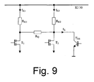
- An electrical equivalent circuit with electrical resistors of the arrangement of FIG. 8 is shown in Fig. 9.
- the two traces with the trace fuses 81, 82 are represented by the resistors R Si1 , R Si2 .
- the electrical cross connection 85 is represented by the resistor R Q.
- I K 2 / I K 1 ( R Si 1 + R Q ) / R Si 2 ,
- the distribution of the short-circuit current I K can be set to the printed conductor fuses 81, 82.
- the short-circuit current can be divided so that in case of short circuit only by one of the fuses a multiple higher current than by the other / other flows.
- the fuse with the higher short-circuit current will therefore burn out first.
- the entire short-circuit current flows through the other conductor track fuse, so that this also burns reliably.
- a step-by-step separation of each individual strip conductor fuse is effected in the case of a plurality of current supply lines to be through-routed. In this way, an excessively low short-circuit current can be prevented for each of the printed circuit fuses to be cut through.
- I K 2 3 * I K 1 ,
- control device is deactivated when switching off the ignition of the motor vehicle.
- selected load circuits can also be connected to the vehicle electrical system be connected to the motor vehicle that you can be activated when the vehicle is parked. A semiconductor failure can thus occur even with the ignition off. The failed power semiconductor device then supplies power to the corresponding load - with the negative consequences described above.
- the control circuit and the motor vehicle in case of failure of a transistor even when the vehicle is turned off two alternative, particular embodiments of the invention are described below.
- the operating voltage of each load circuit U L of the control unit shown in Fig. 5 and Fig. 7 or the voltage regulator is supplied.
- the voltage U L is at the battery level. This voltage is supplied to the voltage regulator, which then supplies the control unit .mu.C with voltage and activated.
- the control unit .mu.C is switched off and all power semiconductors 51 are switched off. Therefore, none of the consumers is supplied with power and the voltage U L is zero. If a semiconductor defect occurs in one of the power semiconductors 51, current flows through the corresponding load circuit and the control unit ⁇ C is automatically activated. As a result of this activation, the fault in the function of one of the power semiconductors 51 is detected and the corresponding power semiconductor (or the group of power semiconductors according to FIG. 7) is disconnected from the power supply by interrupting the printed circuit fuses, as described above.
- control unit .mu.C is also disconnected from the power supply and thus automatically deactivated again.
- control unit .mu.C is activated at periodic intervals.
- the control unit is in a "sleep" mode with a current consumption of only a few ⁇ A.
- an internal timer which is preferably integrated in the voltage regulator or the control unit .mu.C, the control unit changes to the active working mode and checks the proper functionality of the control of the load circuits.
- control unit For periodic monitoring, the control unit preferably switches between the sleep mode and the active working mode at intervals between 10 ms and 1 s. This ensures that the average current consumption remains in the range of less ⁇ A. If a defective power semiconductor 51 is detected, the control unit automatically triggers a disconnection of this power semiconductor from the power supply in the manner according to the invention.
- control device in an electric heating device will be described below.
- the structure of the electric heater with heating elements is first shown as a consumer, in different embodiments for use in motor vehicles.
- FIGS. 10a and 10b An example of an electric heating device for use in motor vehicles is shown in FIGS. 10a and 10b. While Fig. 10b shows a plan view of the electric heater, a side view is shown in Fig. 10a.
- the electric heater 100 has a heater which is composed of a plurality of laminated heaters and radiator elements and heat conduction plates disposed adjacent thereto.
- the heating elements are designed as resistance elements, in particular as PTC heating elements.
- the heater shown in Fig. 10a and Fig. 10b is held in a frame consisting of oppositely arranged longitudinal beams 103 and perpendicular to these arranged side rails 104 and 105 consists.
- the spars of the frame are made of metal or plastic.
- the two longitudinal members 103 shown in FIG. 10b are constructed substantially the same.
- the oppositely disposed side rails 104 and 105 differ in that the side rail 105 is formed as a box open on one side.
- the box-shaped side spar 105 is formed open on the opposite side of the heater.
- a control device can be used, which controls the heat output of the heating stages of the heating register, in particular the PTC heating elements, via a control of the supplied current.
- the open side of the side rail 105 formed as a box can be closed after insertion of the control device with a clip-on or stick-on lid.
- FIG. 11 An example of such a construction is shown in Fig. 11 and will be described in detail below with reference to Fig. 11.
- a control unit is integrated, which adjusts the heating power of the heating elements.
- the control unit is preferably realized in the form of a circuit board having a plurality of power semiconductor components.
- the power semiconductors adjust the current to be supplied to the heating elements in accordance with the control by the control unit.
- the divided by the control unit to the individual heating stages power is supplied via connecting pins 100 of the heater.
- the connecting bolts are designed so that they can easily conduct the required heating currents of up to 200 amperes.
- the heating device in particular in the area of the control unit, is equipped with a plug socket which enables external activation of the heating device, in particular for supplying a heating power requirement.
- the heating power requirement is supplied via a motor vehicle bus.
- a control board with the power semiconductors is arranged in each case at one end of the heating register in a housing section.
- the embodiment shown in Fig. 11 differs from the embodiment shown in Fig. 10 in the structure of the Schuregistergeophuses. While the radiator elements and heating elements according to FIG. 10 are held in a frame formed by bars 103, 104 and 105, according to FIG. 11 the radiator elements 112 and heating elements are held in a plastic housing which is reinforced at the air passage openings via a grid-like structure 113.
- control unit is arranged outside the air duct of the air flow to be heated of a heating air conditioner in a motor vehicle, in a separate housing section.
- the control unit In the air duct of the heating air conditioner of the motor vehicle protrudes only the heating register 111th
- the cooling elements 119 protrude into windows provided in the Schuregisterabites.
- the windows for the cooling elements also protrude into the air duct and give off their heat to the air to be heated. In this way, the power loss produced in the power semiconductors can be dissipated efficiently and energy-saving.
- the heating device 110 shown in FIG. 11 comprises, in addition to the heating register 111, a housing section 114 which receives the control board and a cover 115 which covers the "electronics compartment" of the control electronics.
- the electric heater has the following external connections. Two connecting bolts 108 and 116, 117, via which the heater with ground and the positive pole of the electrical system is connectable.
- the heating device is equipped with a connection 118, via which, in particular, a heating power requirement is transmitted to the control circuit.
- a connection 118 via which, in particular, a heating power requirement is transmitted to the control circuit.
- the transmission of the heating power request and possible further control commands via a motor vehicle data bus, in particular the CAN bus.
- FIGS. 12 and 13 An exemplary implementation of the control circuit of a heating device is shown in FIGS. 12 and 13.
- Fig. 12 is a perspective view of the control circuit of the heater shown in Fig. 11, in which the lid 115 has been removed
- Fig. 13 is a plan view of the control board 120th
- the control board 120 inserted into the housing section 114 distributes the current received via the connection bolt 116 and distributes it via a bus bar 121 to the individual power semiconductors 124 via power supply lines 122, 123.
- the microcontroller 126 ie the control unit
- the power semiconductors 124 supply current to the respective heating stages in accordance with the control signals from the microcontroller 126.
- the microcontroller preferably converts the heating power requirement via a pulse width modulation (PWM) into control signals to the power semiconductors.
- PWM pulse width modulation
- the current is transmitted via contact tongues projecting from the heating register into the spring elements 125.
- the heating device shown in FIG. 12 and FIG. 13 comprises a total of four heating stages, which are each controlled by a power semiconductor 124.
- Each power semiconductor 124 is supplied with power for supply to the heating elements from the bus bar 121 via trace connections 122, 123.
- each power semiconductor adjusts the current to be supplied to each of the heating elements, so that the Power is forwarded accordingly to the PTC heating elements in the heating coil.
- the power semiconductor 124 In the event of a failure of the power semiconductor 124, it is permanently conductive and no longer allows disconnection of the current supplied to the heating elements. In the process, the power loss converted in the power semiconductor 124 increases and excessive heating of this component occurs. This leads to a thermal overload of the entire assembly with the result of scorching and also of other damage in the environment.
- a power semiconductor 124 is connected to its load circuit, i. its power supply, although there is no corresponding control by the control unit 126, an interruption of the power supply to (at least) this power semiconductor 124 is initiated.
- corresponding short circuit switches 130, 131 are provided on the control board 120, which switch the power supply from the power line 121 to this power semiconductor directly to ground, to achieve an interruption in the supply line to the power semiconductor 124 by the current overload of the line.
- conductor track fuses 132 are provided in the current path for all power semiconductors 124.
- the conductor fuses 132 are as Narrowing formed in the current path, each of which does not withstand the short-circuit current
- the design of the fuse corresponds to the fuse concept described in connection with FIGS. 3 to 9.
- electric heaters are used to heat the interior and also the engine. Immediately after the start of the engine this can not provide sufficient heat energy available. This period can be bridged with electric booster heaters.
- Electric heaters are not limited to the automotive field. Electric heaters are also suitable for a variety of other applications, particularly in the field of domestic air conditioning, industrial equipment and the like.
- the electrical booster heaters are preferably for use in a heating air conditioner in motor vehicles.
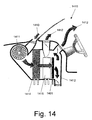
- An example of such a heating air conditioner is shown in FIG.
- the heating air conditioner sucks in outside air 1410 via a blower 1411, which is supplied to the vehicle interior 1413.
- the air previously flows through an evaporator 1414 and a water heat exchanger 1415.
- the water heat exchanger 1415 outputs the heat energy of the cooling water to the air to be supplied to the interior.
- the heated air 1412 flows via corresponding outlets into the motor vehicle interior 1413.
- this task assumes an additional electric heater 101. This is preferably connected downstream of the heat exchanger 1415.
- the present invention relates to an electrical control circuit for controlling a plurality of consumers with an improved security concept.
- the function of a power semiconductor serving to adjust the current supplied to a consumer is monitored.
- the current path to the power semiconductor is permanently interrupted, namely via a short-circuit switch, which jointly cuts through a plurality of power leads to the power semiconductors and thus shuts them off.
- a faulty load switch reliably put out of action and consequential damage with minimal effort, especially for use in motor vehicles can be prevented.
Abstract
Description
Die Erfindung betrifft eine elektrische Steuerschaltung für eine Mehrzahl elektrischer Verbraucher mit erhöhter Sicherheit gegen Ausfall eines in der Steuerschaltung angeordneten Halbleiterschalters, insbesondere für den Einsatz in Kraftfahrzeugen.The invention relates to an electrical control circuit for a plurality of electrical consumers with increased security against failure of a semiconductor switch arranged in the control circuit, in particular for use in motor vehicles.
Halbleiterschalter werden heutzutage in Kraftfahrzeugbordnetzen in großen Stückzahlen und in einer Vielzahl von Anwendungen zum Ein- und Ausschalten von Verbrauchern und auch zum Steuern des Stromflusses durch den Verbraucher eingesetzt. Dabei werden teilweise Ströme bis zu über 50 Ampere geschaltet. Bei einer elektrischen Zusatzheizung als zu steuernder Verbraucher mit einer Heizleistung von beispielsweise 1.600 Watt, die auf vier Stromkreise aufgeteilt ist, kann die Leistungsaufnahme durch Pulsbreitenmodulation (PWM) stufenlos zwischen 0 % und 100 % eingestellt werden. Jeder Stromkreis wird durch einen Halbleiterschalter (vorzugsweise einen MOSFET) periodisch ein- und ausgeschaltet. Dabei fließen durch jeden Halbleiterschalter Ströme von bis zu 50 Ampere.Semiconductor switches are now used in large scale vehicle electrical systems and in a variety of applications for switching consumers on and off as well as controlling the flow of current through the consumer. In some cases, currents up to more than 50 amps are switched. With an electric booster heater as a load to be controlled with a heating power of, for example, 1,600 watts, which is divided into four circuits, the power consumption by pulse width modulation (PWM) can be adjusted continuously between 0% and 100%. Each circuit is periodically turned on and off by a semiconductor switch (preferably a MOSFET). Flow through each semiconductor switch currents of up to 50 amps.
Im Gegensatz zu mechanischen Schaltern wie Relais sind Halbleiterschalter jedoch empfindlich gegen Überlastung. Im Überlastungsfall (EOS - electrical overstress) kann es zu einem "Durchlegieren" des Halbleiterschalters kommen. Der Halbleiterschalter ist dann dauerhaft leitend und nicht mehr abschaltbar.Unlike mechanical switches such as relays, semiconductor switches are sensitive to overloading. In the overload situation (EOS - electrical overstress), it can lead to a "Durchlegieren" of the semiconductor switch. The semiconductor switch is then permanently conductive and can no longer be switched off.
Der leitende Zustand eines Halbleiterschalters ist undefiniert, der Durchlasswiderstand des Schalters in diesem Zustand kann so um ein Mehrfaches höher als der Normalzustand sein. Durch den erhöhten Durchlasswiderstand vergrößert sich der Spannungsabfall in dem Halbleiterbauelement und die umgesetzte Verlustleistung wächst entsprechend an. Die übermäßige Erwärmung des Halbleiterbauteils führt zu einer thermischen Überlastung, die die gesamte Steuerelektronik mit der Folge von Verschmorungen in Mitleidenschaft zieht und auch eine Zerstörung vom Komponenten zur Folge haben kann, die im Umfeld der Heizvorrichtung angeordnet sind.The conductive state of a semiconductor switch is undefined, the on-resistance of the switch in this state may be several times higher than the normal state. Due to the increased forward resistance, the voltage drop increases in the semiconductor device and the converted power dissipation increases accordingly. The excessive heating of the semiconductor device leads to a thermal overload, which affects the entire control electronics with the result of scorching and can also result in destruction of the components, which are arranged in the vicinity of the heater.
Halbleiterschalter zum Schalten hoher Ströme werden heutzutage in Millionenstückzahlen in Kraftfahrzeugen eingebaut. Die Gefahr, dass es trotz der hohen Zuverlässigkeiten von Halbleiterbauelementen mit Ausfallraten im ppm-Bereich zu Schäden am Kraftfahrzeug kommt, ist nicht vernachlässigbar. Zu diesem Zweck sind Sicherungen erforderlich, die im Falle eines dauernd leitenden Halbleiterbauelementes den Stromfluss zuverlässig unterbrechen. Diese Anforderung gilt insbesondere für Anwendungen, bei denen das Halbleiterbauelement und die von diesem gesteuerte Last ständig mit der Fahrzeugbatterie verbunden ist, insbesondere so genannten "Klemme-30-Applikationen". Bei diesen Anwendungen ist auch bei abgestelltem Fahrzeug, d.h. Zündung AUS, eine elektrische Verbindung zwischen der Batterie und der Anwendung vorhanden.Semiconductor switches for switching high currents are now being installed in millions in motor vehicles. The risk of damage to the motor vehicle despite the high reliabilities of semiconductor devices with failure rates in the ppm range is not negligible. Fuses are required for this purpose, which reliably interrupt the current flow in the case of a permanently conductive semiconductor component. This requirement applies in particular for applications in which the semiconductor component and the load controlled by it are permanently connected to the vehicle battery, in particular so-called "terminal-30 applications". In these applications, even when the vehicle is parked, i. Ignition OFF, an electrical connection between the battery and the application exists.
Gemäß einem herkömmlichen Ansatz zur Erhöhung der Sicherheit gegen den Ausfall eines Leistungshalbleiters werden zwei Halbleiterschalter in Reihe geschaltet. Ein Beispiel für eine entsprechende Schaltung ist in Fig. 1 dargestellt. Der Strom IL durch den Lastkreis kann erst dann fließen, wenn beide Leistungshalbleiter eingeschaltet sind. Eine Schutzfunktion wird damit auch bei abgestelltem Fahrzeug erreicht, da in diesem Fall beide Leistungshalbleiter automatisch nicht-leitend geschaltet sind.According to a conventional approach to increase the safety against the failure of a power semiconductor, two semiconductor switches are connected in series. An example of a corresponding circuit is shown in FIG. The current I L through the load circuit can only flow when both power semiconductors are turned on. A protective function is thus achieved even when the vehicle is parked, since in this case both power semiconductors are automatically switched non-conductive.
Nachteilig an dieser herkömmlichen Absicherung eines Halbleiterschalters ist, dass immer zwei Halbleiterbauelemente von dem Laststrom durchflossen sind und eine entsprechende Verlustleistung erzeugen. Beide Halbleiterschalter müssen zur Wärmeabfuhr an ein Kühlelement angebunden werden, so dass der Hardwareaufwand und auch der Platzbedarf deutlich ansteigen. Zusätzlich müssen in der Regel teurere Halbleiterbausteine verwendet werden, um die zusätzlich entstehende Verlustleistung zu vermindern.A disadvantage of this conventional protection of a semiconductor switch is that always two semiconductor components are traversed by the load current and a generate corresponding power loss. Both semiconductor switches must be connected to a cooling element for heat dissipation, so that the hardware costs and space requirements increase significantly. In addition, more expensive semiconductor components usually have to be used in order to reduce the additional power loss.
Eine weitere herkömmliche Alternative zur Absicherung des Ausfalls eines Leistungshalbleiters ist in Fig. 2 gezeigt. Ein thermisches Schutzelement TPE ist in Reihe mit dem Leistungshalbleiter geschaltet. Durch eine thermische Kopplung löst das thermische Schutzelement, beispielsweise eine Schmelzsicherung, bei einer Überhitzung des Halbleiterschalters aus und trennt den Strompfad zum Halbleiterschalter dauerhaft auf.Another conventional alternative for securing the failure of a power semiconductor is shown in FIG. A thermal protection element TPE is connected in series with the power semiconductor. By a thermal coupling triggers the thermal protection element, such as a fuse in case of overheating of the semiconductor switch and separates the current path to the semiconductor switch permanently on.
Nachteilig an einem solchen thermischen Schutzelement ist der erforderliche Bauraum im Bereich des zu schützenden Leistungshalbleiters. Außerdem ist zum Auslösen eines solchen thermischen Schutzelementes eine hohe Temperatur im Bereich von mindestens 200°C am Halbleiterbauelement erforderlich. Da bei der Verwendung von effizienten Kühlkörpern zur Abfuhr der Verlustleistung von dem Halbleiterbauelement solche Temperaturen auch im Fehlerfall nicht immer erreicht werden, ist eine zuverlässige Abschaltung nicht garantiert.A disadvantage of such a thermal protection element is the required installation space in the region of the power semiconductor to be protected. In addition, to initiate such a thermal protection element, a high temperature in the range of at least 200 ° C on the semiconductor device is required. Since with the use of efficient heat sinks to dissipate the power loss of the semiconductor device such temperatures are not always achieved in the event of a fault, a reliable shutdown is not guaranteed.
Aufgabe der Erfindung ist es, eine elektrische Steuerschaltung und ein Verfahren zum Steuern einer Mehrzahl elektrischer Verbraucher anzugeben, die das Risiko, das von einem Transistorausfall ausgeht, vermindern.The object of the invention is to provide an electrical control circuit and a method for controlling a plurality of electrical consumers, which reduce the risk that emanates from a transistor failure.
Diese Aufgabe wird mit den Merkmalen der unabhängigen Patentansprüche gelöst.This object is achieved with the features of the independent claims.
Gemäß einem ersten Aspekt der Erfindung ist eine Steuerschaltung für eine Mehrzahl elektrischer Verbraucher, insbesondere in einem Kraftfahrzeug, angegeben. Die Steuerschaltung umfasst jeweils einen jedem Verbraucher zugeordneten Leistungshalbleiter zur Einstellung des dem Verbraucher zugeführten Stroms und eine Steuereinheit zur Ansteuerung der Leistungshalbleiter. Eine Überwachungseinrichtung erfasst, ob ein Leistungshalbleiter dem jeweiligen Verbraucher Strom zuführt. Ein Unterbrecherelement ist jeweils in der Stromzuführung zu einem Leistungshalbleiter angeordnet. Ein Kurzschlussschalter ist mit der Mehrzahl von Stromzuführungen zu den Leistungshalbleitern verbunden. In Abhängigkeit von einem Kurzschlusssignal der Steuereinheit bewirkt der Kurzschlussschalter über einen Kurzschluss eine Unterbrechung der Unterbrecherelemente. Die Steuereinheit veranlasst eine Unterbrechung der Mehrzahl der mit dem Kurzschlussschalter verbundenen Stromzuführungen durch Aktivierung des Kurzschlussschalters, wenn die Überwachungseinrichtung eine Stromzufuhr zu einem der Verbraucher über einen Leistungshalbleiter feststellt, dessen Stromzuführung mit dem Kurzschlussschalter verbunden ist, ohne dass eine entsprechende Ansteuerung des Leistungshalbleiters durch die Steuereinheit vorliegt.According to a first aspect of the invention, a control circuit for a plurality of electrical consumers, in particular in a motor vehicle, indicated. The control circuit in each case comprises a power semiconductor associated with each consumer for adjusting the current supplied to the consumer and a control unit for controlling the power semiconductors. A monitoring device detects whether a power semiconductor supplies power to the respective consumer. A breaker element is arranged in each case in the power supply to a power semiconductor. A short circuit switch is connected to the plurality of power supply lines to the power semiconductors. Depending on a short-circuit signal of the control unit causes the short-circuit switch via a short circuit, an interruption of the breaker elements. The control unit causes an interruption of the majority of the power supply lines connected to the short-circuit switch by activation of the short-circuit switch, if the monitoring device detects a power supply to one of the consumers via a power semiconductor, whose power supply is connected to the short-circuit switch, without a corresponding control of the power semiconductor by the control unit is present.
Gemäß einem weiteren Aspekt der vorliegenden Erfindung wird ein Verfahren zur Absicherung der Ansteuerung einer Mehrzahl elektrischer Verbraucher, insbesondere in einem Kraftfahrzeug, angegeben. Die Ansteuerung umfasst jeweils einen jedem Verbraucher zugeordneten Leistungshalbleiter zur Einstellung des dem Verbraucher zugeführten Stroms. Die Zuführung von Strom von einem Leistungshalbleiter zu dem jeweiligen Verbraucher wird überwacht. Ein Kurzschlussschalter wird aktiviert, der mit der Mehrzahl von Stromzuführungen zu den Leistungshalbleitern verbunden ist, um die Stromzuführungen zu den mit dem Kurzschlussschalter verbundenen Leistungshalbleitern zu unterbrechen, wenn in dem Überwachungsschritt eine Stromzufuhr zu einem der Verbraucher über einen Leistungshalbleiter festgestellt wird, dessen Stromzuführung mit dem Kurzschlussschalter verbunden ist, ohne dass eine entsprechende Ansteuerung des Halbleiterschalters vorliegt.According to a further aspect of the present invention, a method for securing the activation of a plurality of electrical consumers, in particular in a motor vehicle, is specified. The control comprises a respective power semiconductor associated with each consumer for adjusting the current supplied to the consumer. The supply of current from a power semiconductor to the respective consumer is monitored. A short-circuit switch is activated, which is connected to the plurality of power supply lines to the power semiconductors to interrupt the power supply to the power semiconductors connected to the short-circuit switch, if in the monitoring step, a power supply to one of the consumers via a power semiconductor is detected, the power supply to the Short circuit switch is connected without a corresponding control of the semiconductor switch is present.
Es ist der besondere Ansatz der vorliegenden Erfindung, die Sicherheit von Halbleiterschaltern, insbesondere beim Einsatz in Kraftfahrzeugen, zu erhöhen. Zu diesem Zweck wird erfindungsgemäß die Funktion der Leistungshalbleiter, die den Verbrauchern Strom zuführen, überwacht. Die Stromzuführungen zu der Mehrzahl von Leistungshalbleitern sind mit einem gemeinsamen Kurzschlussschalter verbunden. Wird einer der mit diesem Kurzschlussschalter verbundenen Leistungshalbleiter nicht zur Abgabe von Strom an den zugeordneten Verbraucher angesteuert und führt der Leistungshalbleiter dem Verbraucher dennoch Strom zu, so wird der Kurzschlussschalter aktiviert und die Stromzuführung zu allen mit dem Kurzschlussschalter verbundenen Leistungshalbleitern unterbrochen.It is the particular approach of the present invention to increase the safety of semiconductor switches, especially when used in motor vehicles. For this purpose, according to the invention, the function of the power semiconductors, which supply the consumers with electricity, monitored. The power supply lines to the plurality of power semiconductors are connected to a common shorting switch. If one of the power semiconductors connected to this short-circuit switch is not triggered to supply power to the assigned load and the power semiconductor still supplies the load to the load, then the short-circuit switch is activated and the power supply to all power semiconductors connected to the short-circuit switch is interrupted.
Auf diese Weise wird sowohl der defekte Leistungshalbleiter als auch der mit diesem verbundene Verbraucher bei Ausfall eines Leistungshalbleiters zuverlässig von der Stromzufuhr getrennt. Damit kann bei einem Ausfall des Leistungshalbleiters ein Folgeschaden wirksam verhindert werden, da weder eine Überhitzung des Leistungshalbleiters noch des Verbrauchers stattfinden kann. Somit wird die Sicherheit beim Einsatz von Leistungshalbleitern zum Schalten von Strom in Kraftfahrzeugen deutlich erhöht.In this way, both the defective power semiconductor and the consumer connected to it are reliably disconnected from the power supply in the event of a power semiconductor failure. In order for a failure of the power semiconductor consequential damage can be effectively prevented because neither overheating of the power semiconductor nor the consumer can take place. Thus, the safety is significantly increased when using power semiconductors for switching power in motor vehicles.
Dadurch dass eine Mehrzahl von Leistungshalbleitern über einen gemeinsamen Kurzschlussschalter bei Ausfall eines der mit dem Kurzschlussschalter verbundenen Leistungshalbleiter abgeschaltet wird, kann die zusätzliche Sicherheit mit geringst möglichem zusätzlichen Hardwareaufwand und Platzbedarf erreicht werden.The fact that a plurality of power semiconductors is switched off via a common short-circuit switch in the event of failure of one of the power semiconductors connected to the short-circuiting switch, the additional security with the least possible additional hardware and space requirements can be achieved.
Vorzugsweise ist die Stromüberwachungsfunktion in den Leistungshalbleiter integriert. Durch die Verwendung von "intelligenten" Transistoren, die als Zusatzfunktion eine Strommessung bzw. Spannungsüberwachung des Lastkreises erlauben, kann eine Überwachung der Funktionalität des Leistungshalbleiters in besonders einfacher Weise realisiert werden.Preferably, the current monitoring function is integrated in the power semiconductor. By using "intelligent" transistors, which allow as an additional function current measurement or voltage monitoring of the load circuit, monitoring of the functionality of the power semiconductor can be realized in a particularly simple manner.
Ein Unterbrecherelement ist vorzugsweise ein Leiterbahnabschnitt, dessen Querschnitt so dimensioniert ist, dass eine Unterbrechung bei einem vorgegebenen Stromwert erfolgt. Der Stromwert liegt vorzugsweise um einen festgelegten Betrag oberhalb des maximal den PTC-Heizelementen über die Leiterbahn zugeführten Stroms.A breaker element is preferably a conductor track section whose cross-section is dimensioned so that an interruption occurs at a predetermined current value. The current value is preferably a predetermined amount above the maximum supplied to the PTC heating elements via the conductor current.
Vorzugsweise wird zur Überwachung der Funktionalität des Leistungshalbleiters die Spannung des Lastkreises überwacht. Damit kann auch bei Ausfall einer in den Leistungshalbleiter integrierten Strommessung eine sichere Überwachung erreicht werden.Preferably, the voltage of the load circuit is monitored to monitor the functionality of the power semiconductor. In this way, reliable monitoring can be achieved even if a current measurement integrated in the power semiconductor fails.
Vorzugsweise werden von der Steuereinheit alle Leistungshalbleiter abgeschaltet, wenn eine Unterbrechung der Stromzufuhr zu einem der Leistungshalbleiter bewirkt werden soll. Damit wird garantiert, dass zur Unterbrechung ein maximaler Kurzschlussstrom zur Verfügung steht.Preferably, all power semiconductors are switched off by the control unit if an interruption of the power supply to one of the power semiconductors is to be effected. This guarantees that a maximum short-circuit current is available for interruption.
Die Unterbrechung über den Kurzschlussschalter erfolgt durch Ansteuerung des Kurzschlussschalters für eine vorgegebene Zeitdauer. Anschließend wird die erreichte Wirkung vorzugsweise noch einmal überprüft. Sollte dabei festgestellt werden, dass der betroffene Leistungshalbleiter immer noch Strom den PTC-Heizelementen zuführt, so kann die Ansteuerung des Kurzschlussschalters gegebenenfalls mehrfach wiederholt werden. Dadurch kann eine zuverlässige Abschaltung des ausgefallenen Leistungshalbleiters über die Leiterbahnsicherungen erreicht werden, auch wenn der Kurzschlussstrom aufgrund der Stromentnahme anderer Verbraucher zum Zeitpunkt des ersten erzeugten Kurzschlusses nicht zur Unterbrechung der Stromzuführung zu dem Leistungshalbleiter ausgereicht haben sollte.The interruption via the short-circuit switch is effected by activating the short-circuit switch for a predetermined period of time. Subsequently, the effect achieved is preferably checked again. If it should be determined that the affected power semiconductor is still supplying power to the PTC heating elements, then the activation of the short-circuit switch may possibly be repeated several times. Thereby, a reliable shutdown of the failed power semiconductor can be achieved via the conductor fuses, even if the short-circuit current should not have been due to the current drain of other consumers at the time of the first generated short circuit to interrupt the power supply to the power semiconductor.
Vorzugsweise wird als Kurzschlussschalter ein Relais oder ein Halbleiterschalter verwendet, insbesondere ein IGBT, d.h. ein Insulated Gate Bipolar Transistor.Preferably, a short-circuit switch is a relay or a semiconductor switch, in particular an IGBT, i. an insulated gate bipolar transistor.
Vorzugsweise werden die einzelnen Stromzuführungen, die mit demselben Kurzschlussschalter verbunden sind, aufeinanderfolgend aufgetrennt. Damit ist sichergestellt, dass der Kurzschlussstrom jeweils zur Durchtrennung der jeweiligen Stromzuführung ausreichend ist. Auf diese Weise kann auch bei schwacher Batterie eines Kraftfahrzeugs eine sichere Abschaltung erreicht werden.Preferably, the individual power supply lines, which are connected to the same short-circuit switch, successively separated. This ensures that the short-circuit current is sufficient in each case for the separation of the respective power supply. In this way, a safe shutdown can be achieved even with low battery of a motor vehicle.
Vorzugsweise werden die Unterbrecherelemente schrittweise durchtrennt, und zwar ausgehend von dem Unterbrecherelement, das zu dem Kurzschlussschalter benachbart angeordnet ist. Mit jeder Durchtrennung einer Stromzuführung wird ein maximale Kurzschlussstrom der benachbarten, von dem Kurzschlussschalter jeweils weiter entfernten Stromzuführung zur Verfügung gestellt und damit schrittweise eine Durchtrennung aller Unterbrecherelemente der "sicherheitstechnisch gekoppelten" Leistungshalbleiter bewirkt.Preferably, the breaker elements are severed stepwise, starting from the breaker element located adjacent to the shorting switch. With each cut through a power supply, a maximum short-circuit current of the adjacent, each of the short-circuit switch more distant power supply is provided and thus gradually a separation of all breaker elements of the "safety-coupled" power semiconductor causes.
Vorzugsweise sind zwei benachbarte Stromzuführungen zu den Leistungshalbleitern über einen Quersteg miteinander verbunden. In dieser Art kann eine beliebige Anzahl von Stromzuführungen mit dem Kurzschlussschalter verbunden werden. Dazu verbindet der Quersteg vorzugsweise jeweils die Leitungsabschnitte der Stromzuführungen zwischen dem Unterbrecherelement und dem Leistungshalbleiter. Durch geeignete Dimensionierung des elektrischen Widerstandes des Quersteges lässt sich der im Kurzschlussfall an den einzelnen Stromzuführungen anliegende Kurzschlussstrom einstellen.Preferably, two adjacent power supply lines to the power semiconductors are connected to one another via a transverse web. In this way, any number of power supplies can be connected to the shorting switch. For this purpose, the cross bar preferably connects in each case the line sections of the power supply lines between the breaker element and the power semiconductor. By suitable dimensioning of the electrical resistance of the transverse web, the short-circuit current applied to the individual power supply leads can be set in the event of a short circuit.
Die elektrischen Widerstände des Querstegs und der Unterbrecherelemente werden so ausgelegt, dass gleichzeitig vorzugsweise jeweils nur durch ein Unterbrecherelement ein ausreichend hoher Kurzschlussstrom fließt. Damit lässt sich in einfacher Weise eine sichere, aufeinanderfolgende Abschaltung der Leistungshalbleiter, die mit einem Kurzschlussschalter verbunden sind, erreichen.The electrical resistances of the cross bar and the breaker elements are designed so that at the same time preferably only by a breaker element, a sufficiently high short-circuit current flows. This can be in a simple way, a safe, successive shutdown of the power semiconductors, which are connected to a short-circuit switch reach.
Weitere vorteilhafte Ausgestaltung der Erfindung sind Gegenstand der Unteransprüche.Further advantageous embodiment of the invention are the subject of the dependent claims.
Im Folgenden wird die Erfindung anhand der beiliegenden Zeichnungen beschrieben, in denen:
- Fig. 1
- die Schaltung einer herkömmlichen Absicherung eines Halbleiterschalters in einem Kraftfahrzeug durch Reihenschaltung von zwei Halbleiterschaltern zeigt,
- Fig. 2
- eine weitere Schaltung einer alternativen herkömmlichen Absicherung eines Halbleiterschalters in einem Kraftfahrzeug durch eine thermische Sicherung zeigt,
- Fig. 3
- schematisch den Aufbau des der erfindungsgemäßen Absicherung zugrundeliegenden Konzepts wiedergibt,
- Fig. 4
- ein Ablaufdiagramm des Verfahrens zum Betreiben der Absicherung gemäß Fig. 3 zeigt,
- Fig. 5
- eine beispielhafte Schaltung zur Absicherung eines Halbleiterschalters gemäß dem Aufbau aus Fig. 3 zeigt
- Fig. 6
- schematisch den Aufbau einer Leiterbahnsicherung für die Schaltung gemäß Fig. 7 zeigt,
- Fig. 7
- eine beispielhafte Schaltung für eine erfindungsgemäße gleichzeitige Absicherung einer Mehrzahl von Halbleiterschaltern zeigt,
- Fig. 8
- ein Beispiel für ein Leiterbahnlayout einer Leitbahnsicherung von zwei Leistungshalbleitern über einen gemeinsamen Kurzschlussschalter zeigt,
- Fig. 9
- eine elektrische Ersatzschaltung für die Leiterbahnstruktur der Fig. 8 zeigt,
- Fig. 10a
- eine Seitenansicht einer elektrischen Heizvorrichtung mit Halbleiterschaltern zum Ansteuern einer Mehrzahl von Heizstufen zeigt,
- Fig. 10b
- eine Aufsicht auf die elektrische Heizvorrichtung gemäß Fig. 10a zeigt,
- Fig. 11
- eine perspektivische Ansicht eines zu Fig. 10 alternativen Aufbaus einer elektrischen Heizvorrichtung zeigt,
- Fig. 12
- eine perspektivische Ansicht einer Steuerschaltung der in Fig. 11 gezeigten Heizvorrichtung zeigt,
- Fig. 13
- eine Aufsicht auf die in Fig. 12 dargestellte Steuerschaltung zeigt und
- Fig. 14
- schematisch den Aufbau eines Heiz-Klimagerätes in einem Kraftfahrzeug mit eine elektrischen Heizvorrichtung zeigt.
- Fig. 1
- shows the circuit of a conventional fuse of a semiconductor switch in a motor vehicle by series connection of two semiconductor switches,
- Fig. 2
- shows a further circuit of an alternative conventional protection of a semiconductor switch in a motor vehicle by a thermal fuse,
- Fig. 3
- schematically shows the structure of the inventive concept underlying the hedge,
- Fig. 4
- FIG. 3 shows a flowchart of the method for operating the protection according to FIG. 3,
- Fig. 5
- an exemplary circuit for securing a semiconductor switch according to the structure of Fig. 3 shows
- Fig. 6
- schematically shows the structure of a conductor track fuse for the circuit of FIG. 7,
- Fig. 7
- shows an exemplary circuit for a simultaneous protection of a plurality of semiconductor switches according to the invention,
- Fig. 8
- shows an example of a track layout of a track protection of two power semiconductors via a common short-circuit switch,
- Fig. 9
- FIG. 8 shows an electrical equivalent circuit for the printed conductor structure of FIG. 8, FIG.
- Fig. 10a
- shows a side view of an electric heater with semiconductor switches for driving a plurality of heating stages,
- Fig. 10b
- shows a plan view of the electric heater of FIG. 10a,
- Fig. 11
- shows a perspective view of an alternative to Fig. 10 construction of an electric heater,
- Fig. 12
- FIG. 4 shows a perspective view of a control circuit of the heating device shown in FIG. 11, FIG.
- Fig. 13
- a plan view of the control circuit shown in FIG. 12 shows and
- Fig. 14
- schematically shows the structure of a heating air conditioner in a motor vehicle with an electric heater.
Die Erfindung betrifft Steuerschaltungen mit Leistungshalbleitern, die den den jeweils angeschlossenen Verbrauchern zuzuführenden Strom einstellen. Die Stromeinstellung erfolgt in Abhängigkeit von einem externen Signal, das der Steuerschaltung zugeführt wird.The invention relates to control circuits with power semiconductors that adjust the current supplied to each connected loads. The current adjustment is made in response to an external signal supplied to the control circuit.
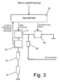
Das Prinzip, das der vorliegenden Erfindung zugrunde liegt, ist in dem schematisch dargestellten Aufbau des Sicherungskonzeptes einer Steuerschaltung in Fig. 3 wiedergegeben. Eine Steuereinheit 30 der Steuerschaltung erhält ein von außen zugeführtes Steuersignal, beispielsweise eine Heizleistungsanforderung für eine elektrische Heizvorrichtung. Das extern zugeführte Signal wird von der Steuerschaltung 30 in eine Ansteuerung, insbesondere eine Zu- bzw. Abschaltung der Verbraucher 32 umgesetzt. Der Einfachheit halber ist in Fig. 3 nur ein einziger Lastkreis mit Verbrauchern 32 dargestellt. In entsprechender Weise kann jedoch eine Vielzahl von Verbrauchern von der Steuereinheit 30 angesteuert werden. Die erfindungsgemäße Stromsicherung ist dabei gemeinsam für eine vorgegebene Mehrzahl von Leistungshalbleitern vorgesehen.The principle underlying the present invention is shown in the schematically illustrated construction of the fuse concept of a control circuit in Fig. 3. A
Die Steuereinheit 30 stellt den den Verbrauchern 32 zugeführten Strom ein. Über eine Stromüberwachung 33 wird die Funktion der Leistungshalbleiter 31 kontrolliert, die in Abhängigkeit von der Ansteuerung durch die Steuereinheit 30 den jeweils erforderlichen Strom den Verbrauchern 32 zuführen.The
Die Stromüberwachung kann entweder über eine Strommessung oder alternativ über eine Überwachung der an dem Lastkreis des Leistungshalbleiters 31 anliegenden Spannung UL realisiert werden. Vorzugsweise ist die Überwachungsfunktion des Lastkreises in den Leistungshalbleiter integriert (durch die gestrichelte Einfassung der Blöcke 31 und 33 in Fig. 3 angedeutet).The current monitoring can be realized either via a current measurement or alternatively via a monitoring of the voltage U L applied to the load circuit of the
Stellt die Steuereinheit 30 fest, dass ein Strom von dem Leistungshalbleiter 31 den zugeordneten Verbrauchern 32 zugeführt wird, obwohl der Leistungshalbleiter nicht entsprechend angesteuert wird, so leitet die Steuereinheit 30 eine Unterbrechung der Stromzufuhr zu dem Leitungshalbleiter 31 ein.If the
Vorzugsweise wird die Unterbrechung über eine Leiterbahnsicherung erreicht, die einem Kurzschlussstrom nicht standhält. Die Steuereinheit 30 erzeugt zu diesem Zweck ein Unterbrechungssignal, über das ein Kurzschlussschalter 34 die Stromzufuhr zu dem Leitungshalbleiter 31 kurzschließt. Diesem Kurzschlussstrom, der höher als der im ordnungsgemäßen Betrieb maximal fließende Strom ist, hält die im Strompfad liegende Leiterbahnsicherung 35 nicht stand. Das Leiterbahnstück 35 brennt an der Engstelle durch und unterbricht damit dauerhaft den Stromfluss zu dem Leitungshalbleiter 31. Auf diese Weise kann zuverlässig ein fehlerhaftes Halbleiterbauelement erkannt und dauerhaft außer Betrieb gesetzt werden.Preferably, the interruption is achieved via a conductor track fuse, which does not withstand a short-circuit current. The
Das entsprechende Verfahren ist in dem Ablaufdiagramm der Fig. 4 dargestellt. In Abhängigkeit von einer externen Steuerungsanforderung werden die Leistungshalbleiter 31 im Schritt S1 angesteuert. Das tatsächliche Funktionieren der Leistungshalbleiter wird im Schritt S2 überwacht. Dazu wird erfasst, ob der Lastkreis des jeweiligen Leistungshalbleiters stromführend ist. Eine nicht ordnungsgemäße Funktionalität des Leistungshalbleiters liegt vor, wenn der Lastkreis stromführend ist, der Leistungshalbleiter jedoch nicht von der Steuereinheit entsprechend angesteuert wird (Schritt S3). Daraufhin wird im Schritt S4 die Stromzufuhr zu dem Leistungshalbleiter unterbrochen.The corresponding method is shown in the flowchart of FIG. 4. In response to an external control request, the
Um zuverlässig eine dauerhafte Unterbrechung der Stromzufuhr bei einer Mehrzahl separat angesteuerter Verbraucher erreichen zu können, werden vorzugsweise vor Aktivierung des Kurzschlussschalters 34 alle (abschaltbaren) Verbraucher abgeschaltet. Damit fließt kein Strom über die anderen Verbraucher ab und es kann ein möglichst hoher Kurzschlussstrom und damit eine sichere Unterbrechung der Zuleitung zu dem ausgefallenen Leistungshalbleiter 31 erreicht werden.In order to be able to reliably achieve a permanent interruption of the power supply in a plurality of separately controlled consumers, preferably all (disconnectable) consumers are switched off before activation of the short-
Zur Unterbrechung der Zuleitung zu dem ausgefallenen Leistungshalbleiter wird der Kurzschlussschalter 34 nur für eine kurze Zeit TBr aktiviert. Diese Zeitspanne ist so ausgelegt, dass der während dieser Zeitdauer fließende Kurzschlussstrom die Leiterbahnsicherung 35 sicher auftrennen sollte.To interrupt the supply to the failed power semiconductor, the short-
Die Sicherheit, bei Ausfall eines Leistungshalbleiters diesen zuverlässig abzuschalten, kann dadurch weiter erhöht werden, dass nach Ablauf der Zeitspanne TBr eine Überprüfung durchgeführt wird, ob die Stromzuführung zu dem ausgefallenen Leistungshalbleiter tatsächlich unterbrochen ist. Dazu wird, wie zuvor im Schritt S2, überprüft, ob der Lastkreis des Leitungshalbleiters stromdurchflossen ist. Wird dabei festgestellt, dass die Stromzufuhr nicht unterbrochen ist, so wird der Schritt S4 gegebenenfalls mehrfach wiederholt.The security of switching off this reliably in the event of a power semiconductor failure can be further increased by carrying out a check after expiry of the time period T Br as to whether the power supply to the failed power semiconductor has actually been interrupted. For this purpose, as previously in step S2, checks whether the load circuit of the line semiconductor is current-flowing. If it is found that the power supply is not interrupted, the step S4 is repeated if necessary several times.
In Fig. 5 ist beispielhaft eine sichere Steuerschaltung für die Ansteuerung von Halbleiterschaltern dargestellt. Die Steuereinheit µC stellt über den Halbleiterschalter 51 jedem Verbraucher den von der Batterie 55 zuzuführenden Strom ein. Entsprechend der Ansteuerung der Halbleiterschalter 51 durch die Steuereinheit wird den Verbrauchern 52 Strom zugeführt.In Fig. 5 a safe control circuit for the control of semiconductor switches is exemplified. The control unit .mu.C uses the
Zusätzlich sind in Fig. 5 zwei Kurzschlussschalter 53 dargestellt, die jeweils einem Leistungshalbleiter 51 zugeordnet sind. Als Kurzschlussschalter werden vorzugsweise Halbleiterschalter mit einer hohen Stromtragfähigkeit verwendet.In addition, two short-
Zusätzlich ist in den Strompfad zu den jeweiligen Leistungshalbleitern 51 eine Sicherung 54 geschaltet. Diese Sicherung ist vorzugsweise als Leiterbahnsicherung ausgestaltet. Wird einer der Kurzschlussschalter 53 von Steuereinheit leitend geschaltet, so wird die Stromzufuhr zu dem zu schützenden Leistungshalbleiter 51 und zu dem mit diesem verbundenen Verbraucher dauerhaft unterbrochen.In addition, a
Durch die Ausbildung der Sicherung 54 als Leiterbahnsicherung ist diese Bestandteil der Leiterbahnstruktur und muss nicht als zusätzliches Bauteil montiert oder bestückt werden.Due to the formation of the
Im Gegensatz zur bekannten Schmelzsicherung löst das beschriebene Sicherungskonzept nicht passiv aufgrund eines erhöhten Stroms durch den Verbraucher, d.h. des Lastkreises aus. Ein erhöhter Lastkreisstrom kann beispielsweise durch einen Kurzschluss in der Last verursacht sein. Im Gegensatz dazu ist ein separater Kurzschlusspfad vorgesehen, in dem bei Aktivierung des Kurzschlussschalters ein erhöhter Strom fließt und ein Auslösen der Sicherung bewirkt. Anders als bei herkömmlichen Sicherungskonzepten wird nicht ein fehlerhafter Verbraucher abgeschaltet, sondern zuverlässig ein fehlerhafter Leistungshalbleiter.In contrast to the known fuse, the fuse concept described does not passively solve because of an increased current through the consumer, i. of the load circuit. An increased load circuit current can be caused for example by a short circuit in the load. In contrast, a separate short-circuit path is provided in which, when the short-circuit switch is activated, an increased current flows and triggers the fuse. Unlike conventional security concepts, it is not a faulty consumer that is shut down, but rather a faulty power semiconductor.
Eine beispielhafte Gestaltung einer solchen Leiterbahnsicherung 54 ist in Fig. 6 dargestellt. Die Leiterbahnsicherung 60 ist vorzugsweise als Engstelle 62 mit der Breite BE in einem Leiterbahnzug 61 mit der Breite B angeordnet. Durch die Engstelle 62 kommt es in einem im Vergleich zu einer Gesamtlänge LG der Leiterbahn 60 kurzen Leiterbahnstück der Länge LE zu einer deutlichen Erhöhung des Widerstandes pro Länge. Damit bleibt der Gesamtwiderstand des Leiterbahnzuges und damit auch der Spannungsabfall über diesem nahezu unverändert niedrig, an der Engstelle 62 kommt es dagegen zu einem deutlichen Spannungsabfall ΔU.An exemplary design of such a
Im Kurzschlussfall kommt es durch den Kurzschlussstrom IK an der Engstelle 62 zu einer Verlustleistung PV mit einer starken Erwärmung, so dass das Leiterbahnstück 60 an der Engstelle 62 durchbrennt. Damit sind der Leiterbahnzug und der Stromfluss unterbrochen.In the event of a short circuit, due to the short-circuit current I K at the
An der Engstelle 62 ist die Leiterbahn typischerweise aus einer Kupferfolie mit einer Dicke von 35 bis 70 µm ausgebildet. Durch eine geeignete Dimensionierung wird gewährleistet, dass im Normalbetrieb, wenn der Nennstrom IN mit IN << IK fließt, die Erwärmung an der Engstelle 62 gering ist. Im Normalbetrieb kommt es somit nicht zu einem Durchbrennen des Leiterbahnstücks an der Engstelle 62.At the
Um ein zuverlässiges Durchbrennen der Leiterbahnsicherung 60 im Ansprechfall zu gewährleisten, muss der für das Durchbrennen erforderliche Kurzschlussstrom IK fließen. Der Kurzschlussstrom wird im Wesentlichen durch die Bordnetzspannung UB und über die Zuleitungswiderstände RZul bestimmt. In erster Näherung gilt: ![]()
![]()
Elektrische Steuerschaltungen zur Einstellung des einer Mehrzahl von Verbrauchern zuzuführenden Stroms weisen im Allgemeinen mehrere, getrennt schaltbare Lastkreise auf. Dadurch sind die Zuleitungswiderstände RZul ausreichend niedrig, da die Zuleitungen nicht auf den Nennstrom eines Lastkreises, sondern auf den Summenstrom aller Lastkreise ausgelegt sind. In Fig. 5 sind beispielsweise zwei Lastkreise mit entsprechenden Verbrauchern 52 dargestellt, denen der benötigte Strom über die Leistungshalbleiter 51 zugeführt wird.Electrical control circuits for adjusting the current to be supplied to a plurality of consumers generally have a plurality of load circuits that can be switched separately. As a result, the supply line resistances R Zul are sufficiently low, since the supply lines are not designed for the nominal current of a load circuit but for the total current of all load circuits. In FIG. 5, for example, two load circuits with corresponding
Um den Fehlerfall zu detektieren und die Leiterbahnsicherung auszulösen, wird zunächst die Erkennung eines nicht abschaltbaren Leistungshalbleiters durchgeführt. Zu diesem Zweck wird bei in der in Fig. 5 gezeigten Ausführungsform die Spannung UL des Lastkreises des Leistungshalbleiters 51 abgefragt. Bei einem nicht angesteuerten Leistungshalbleiter 51 ist der Lastkreis nicht stromdurchflossen und die Spannung daher 0 Volt. Wird jedoch eine Spannung UL größer als 0 Volt festgestellt, so ist der Leistungshalbleiter 51 trotz fehlender Ansteuerung leitend. In diesem Fall leitet die Steuereinheit eine Unterbrechung der Stromzufuhr zu diesem Leistungshalbleiter ein.In order to detect the error case and to trigger the conductor track fuse, the detection of a non-disconnectable power semiconductor is initially performed. For this purpose, in the embodiment shown in FIG. 5, the voltage U L of the load circuit of the
Um ein sicheres Durchbrennen der entsprechenden Leiterbahnsicherung 54 zu gewährleisten, werden in einem ersten Schritt alle Lastkreise abgeschaltet. Mit dieser Maßnahme wird gewährleistet, dass der Kurzschlussstrom IK vollständig zum Durchbrennen der Leiterbahnsicherung zur Verfügung steht. Anschließend wird der Kurzschlussschalter 53 für eine festgelegte Zeit TBr angesteuert.In order to ensure a secure burnout of the
Nach Ablauf der vorgegebenen Zeitspanne TBr wird überprüft, ob die Leiterbahnsicherung 54 tatsächlich durchgebrannt ist bzw. die Mehrzahl von Leiterbahnsicherungen. Zu diesem Zweck wird wiederum die Spannung UL des Lastkreises des entsprechenden Leistungshalbleiters 51 abgefragt. Gegebenenfalls werden die letzten beiden Schritte wiederholt durchgeführt, nämlich die Ansteuerung des Kurzschlussschalters 53 und die Überprüfung, ob die Leiterbahnsicherung tatsächlich durchgebrannt ist.After the predetermined period of time T Br has elapsed, it is checked whether the printed
Als Kurzschlussschalter 53 kommen vorzugsweise Halbleiterschalter IGBTs oder Bipolartransistoren zum Einsatz, aber auch MOSFETs oder Thyristoren. Grundsätzlich sind ebenfalls elektromechanische Schalter in Form von Relais als Kurzschlussschalter verwendbar.As a short-
Eine erfindungsgemäße Implementierung des Sicherungskonzeptes für eine elektrische Steuerschaltung ist in Fig. 7 dargestellt. Um den zusätzlichen Hardwareaufwand und insbesondere auch den zusätzlichen Platzbedarf auf einer Steuerplatine zu vermindern, der durch das Sicherungskonzept erforderlich ist, wird ein Kurzschlussschalter 70 gleichzeitig zur Absicherung einer Mehrzahl von Lastkreisen verwendet. Der in Fig. 7 gezeigte Kurzschlussschalter 70 ersetzt die beiden in Fig. 5 dargestellten Kurzschlussschalter 53, die jeweils nur einem einzigen Leistungshalbleiter zugeordnet waren. Der Kurzschlussschalter 70 dient vorzugsweise zur Absicherung von zwei Lastkreisen, es ist aber auch jede andere Anzahl von entsprechend gekoppelten Lastkreisen möglich. Damit kann die Anzahl der zusätzlich erforderlichen Halbleiterbausteine für die Kurzschlussschalter und der zusätzliche Platzbedarf so gering wie möglich gehalten werden.An inventive implementation of the fuse concept for an electrical control circuit is shown in FIG. To the additional hardware expenditure and in particular also to reduce the extra space required on a control board required by the backup concept, a short-
Mit dem in Fig. 7 gezeigten Sicherungskonzept werden im Fehlerfall zwei Leiterbahnsicherungen 54 mit der Auslösung des Kurzschlussschalters 70 durchtrennt. Eine beispielhafte Ausgestaltung für zwei entsprechend verbundene Leiterbahnsicherungen ist in Fig. 8 dargestellt.With the fuse concept shown in FIG. 7, in the event of a fault, two printed conductor fuses 54 are severed with the tripping of the short-
Zwischen der ersten Leiterbahn-Sicherung 81 und dem zugehörigen Leistungshalbleiter T1 und der Leiterbahn-Sicherung 82 mit dem dazugehörigen Leistungshalbleiter T2 befindet sich ein Quersteg 85 als elektrische Querverbindung, vorzugsweise in Form einer Leiterbahn. Jedes Stück Leiterbahn der in Fig. 8 gezeigten beispielhaften Implementierung besitzt eine endliche elektrische Leitfähigkeit, die bei hohen Strömen nicht vernachlässigbar ist und zu Spannungsabfällen führt. Eine elektrische Ersatzschaltung mit elektrischen Widerständen der Anordnung nach Fig. 8 ist in Fig. 9 wiedergegeben.Between the
Die beiden Leiterbahnzüge mit den Leiterbahn-Sicherungen 81, 82 werden durch die Widerstände RSi1, RSi2 repräsentiert. Die elektrische Querverbindung 85 wird durch den Widerstand RQ dargestellt. Bei durchgeschaltetem Kurzschlussschalter 70 (TKS) teilt sich der Kurzschlussstrom IK auf die beiden Zweige auf, nämlich durch den Widerstand RSi2 und durch die Reihenschaltung aus RSi1 und RQ. Für den Stromfluss gilt: 
Für die Stromaufteilung auf die beiden Zweige gilt: ![]()
![]()
Durch geeignete Wahl der Widerstände RSi1, RSi2, RQ lässt sich die Aufteilung des Kurzschlussstroms IK auf die Leiterbahnsicherungen 81, 82 einstellen. Damit lässt sich der Kurzschlussstrom so aufteilen, dass im Kurzschlussfall nur durch eine der Sicherungen ein um ein Mehrfaches höherer Strom als durch die andere/anderen fließt. Die Sicherung mit dem höheren Kurzschlussstrom wird daher zunächst durchbrennen. Anschließend fließt der gesamte Kurzschlussstrom über die andere Leiterbahnsicherung, so dass auch diese zuverlässig durchbrennt. Erfindungsgemäß wird daher bei einer Mehrzahl durchzutrennender Stromzuführungen eine schrittweise Durchtrennung jeder einzelnen Leiterbahnsicherung bewirkt. Auf diese Weise kann sicher ein zu niedriger Kurzschlussstrom für jede der durchzutrennenden Leiterbahnsicherungen verhindert werden.By a suitable choice of the resistors R Si1 , R Si2 , R Q , the distribution of the short-circuit current I K can be set to the printed conductor fuses 81, 82. Thus, the short-circuit current can be divided so that in case of short circuit only by one of the fuses a multiple higher current than by the other / other flows. The fuse with the higher short-circuit current will therefore burn out first. Subsequently, the entire short-circuit current flows through the other conductor track fuse, so that this also burns reliably. According to the invention, therefore, a step-by-step separation of each individual strip conductor fuse is effected in the case of a plurality of current supply lines to be through-routed. In this way, an excessively low short-circuit current can be prevented for each of the printed circuit fuses to be cut through.
Die aufeinanderfolgende Durchtrennung der Leiterbahnsicherungen einer "Sicherungsgruppe" wird im folgenden Ausführungsbeispiel erläutert. Dazu wird angenommen, dass: ![]()

![]()
Demzufolge ergibt sich: ![]()
![]()
![]()
![]()
Im Kurzschlussfall fließen demgemäss zunächst 75 % des Kurzschlussstroms IK durch die Leiterbahnsicherung 82. Nachdem die Leiterbahnsicherung 82 durchgebrannt ist, fließt der gesamte Kurzschlussstrom (100 %) durch die zweite Leiterbahnsicherung 81. Damit ist ein sicheres Durchbrennen beider Leiterbahnsicherungen 81, 82 gewährleistet, um den Stromfluss durch die Lastkreise beider Leistungshalbleiter 51 bei einem Defekt eines der beiden Halbleiterschalter 51 sicher zu unterbrechen.In the event of a short circuit, initially 75% of the short-circuit current I K flow through the printed
Das obengenannte Ausführungsbeispiel dient nur der Illustration der besonderen Ausgestaltung der vorliegenden Erfindung. Selbstverständlich sind beliebige andere Kombinationen von Widerständen RSi1, RSi2, RQ bzw. Auslegungen der beiden Leiterbahnsicherungen 81, 82 und des Querstegs 85 möglich. Die vorliegende Erfindung ist nicht auf die oben beschriebene Auslegung der Widerstände eingeschränkt. Ebenso ist die vorliegende Erfindung nicht auf die Verwendung von einer Gruppe aus allein zwei Leiterbahnsicherungen 81, 82 die über einen Quersteg miteinander verbunden sind, beschränkt. Eine beliebige Anzahl von Leistungshalbleitern 51 kann in entsprechender Weise abgesichert werden.The above embodiment is only illustrative of the particular embodiment of the present invention. Of course, any other combinations of resistors R Si1 , R Si2 , R Q and interpretations of the two conductor fuses 81, 82 and the
Normalerweise wird die Steuervorrichtung beim Ausschalten der Zündung des Kraftfahrzeugs deaktiviert. Ausgewählte Lastkreise können jedoch auch so an das Bordnetz des Kraftfahrzeugs angeschlossen sein, dass Sie bei abgestelltem Fahrzeug aktivierbar sind. Ein Halbleiterausfall kann somit auch bei ausgeschalteter Zündung auftreten. Das ausgefallene Leistungshalbleiterbauelement führt dann Strom dem entsprechenden Verbraucher zu - mit den oben beschriebenen negativen Folgen. Um auch bei abgestelltem Kraftfahrzeug einen Schaden für die den Verbraucher, die Steuerschaltung und das Kraftfahrzeug bei Ausfall eines Transistors zu vermeiden, werden nachfolgend zwei alternative, besondere Ausgestaltungen der Erfindung beschrieben.Normally, the control device is deactivated when switching off the ignition of the motor vehicle. However, selected load circuits can also be connected to the vehicle electrical system be connected to the motor vehicle that you can be activated when the vehicle is parked. A semiconductor failure can thus occur even with the ignition off. The failed power semiconductor device then supplies power to the corresponding load - with the negative consequences described above. In order to avoid damage to the consumer, the control circuit and the motor vehicle in case of failure of a transistor even when the vehicle is turned off, two alternative, particular embodiments of the invention are described below.
Gemäß einer ersten Ausführungsform zur Absicherung der Steuerschaltung gegen einen Ausfall eines Leistungshalbleiters bei Zündung AUS wird die Betriebsspannung jedes Lastkreises UL der in Fig. 5 und Fig. 7 gezeigten Steuereinheit bzw. dem Spannungsregler zugeführt.According to a first embodiment for protecting the control circuit against a failure of a power semiconductor at ignition OFF, the operating voltage of each load circuit U L of the control unit shown in Fig. 5 and Fig. 7 or the voltage regulator is supplied.
Sobald einer der Leistungshalbleiter 51 ausfällt und ständig leitend ist, liegt die Spannung UL auf Batterieniveau. Diese Spannung wird dem Spannungsregler zugeführt, der daraufhin die Steuereinheit µC mit Spannung versorgt und aktiviert.As soon as one of the
Bei der Stellung Zündung AUS des Kraftfahrzeugs ist die Steuereinheit µC abgeschaltet und alle Leistungshalbleiter 51 gesperrt geschaltet. Keiner der Verbraucher ist daher mit Strom versorgt und die Spannung UL ist Null. Tritt ein Halbleiterdefekt in einem der Leistungshalbleiter 51 auf, so ist der entsprechende Lastkreis von Strom durchflossen und die Steuereinheit µC wird automatisch aktiviert. Durch diese Aktivierung wird der Fehler in der Funktion einer der Leistungshalbleiter 51 detektiert und der entsprechende Leistungshalbleiter (bzw. die Gruppe von Leistungshalbleitern gemäß Fig. 7) von der Stromzuführung durch Unterbrechung der Leiterbahnsicherungen - wie oben beschrieben - getrennt.In the ignition OFF position of the motor vehicle, the control unit .mu.C is switched off and all
Mit der erfolgreichen Trennung des defekten Leistungshalbleiters 51 von der Stromversorgung ist auch die Steuereinheit µC von der Stromzufuhr getrennt und damit anschließend wieder automatisch deaktiviert.With the successful separation of the
Gemäß einer zweiten alternativen Ausführungsform wird die Steuereinheit µC in periodischen Zeitabständen aktiviert. Zu diesem Zweck befindet sich die Steuereinheit in einem "Sleep"-Modus mit einer Stromaufnahme von nur wenigen µA. Durch einen internen Zeitgeber, der vorzugsweise in den Spannungsregler oder die Steuereinheit µC integriert ist, wechselt die Steuereinheit in den aktiven Arbeitsmodus und überprüft die ordnungsgemäße Funktionalität der Ansteuerung der Lastkreise.According to a second alternative embodiment, the control unit .mu.C is activated at periodic intervals. For this purpose, the control unit is in a "sleep" mode with a current consumption of only a few μA. By an internal timer, which is preferably integrated in the voltage regulator or the control unit .mu.C, the control unit changes to the active working mode and checks the proper functionality of the control of the load circuits.
Zur periodischen Überwachung wechselt die Steuereinheit vorzugsweise in Zeitabständen zwischen 10ms und 1s zwischen dem Sleep-Modus und dem aktiven Arbeitsmodus. Damit wird erreicht, dass die mittlere Stromaufnahme im Bereich weniger µA bleibt. Wird ein defekter Leistungshalbleiter 51 erkannt, löst die Steuereinheit automatisch ein Abtrennen dieses Leistungshalbleiters von der Stromversorgung in der erfindungsgemäßen Weise aus.For periodic monitoring, the control unit preferably switches between the sleep mode and the active working mode at intervals between 10 ms and 1 s. This ensures that the average current consumption remains in the range of less μA. If a
Nachfolgend wird der Einsatz der erfindungsgemäßen Steuervorrichtung in einer elektrischen Heizvorrichtung beschrieben. Dazu wird zunächst der Aufbau der elektrischen Heizvorrichtung mit Heizelementen als Verbraucher dargestellt, und zwar in unterschiedlichen Ausführungsformen zum Einsatz in Kraftfahrzeugen.The use of the control device according to the invention in an electric heating device will be described below. For this purpose, the structure of the electric heater with heating elements is first shown as a consumer, in different embodiments for use in motor vehicles.
Ein Beispiel einer elektrischen Heizvorrichtung für den Einsatz in Kraftfahrzeugen ist in Fig. 10a und Fig. 10b dargestellt. Während Fig. 10b eine Aufsicht auf die elektrische Heizvorrichtung zeigt, ist in Fig. 10a eine Seitenansicht wiedergegeben. Die elektrische Heizvorrichtung 100 weist ein Heizregister auf, das aus einer Mehrzahl geschichteter Heizelemente und benachbart zu diesen angeordneten Radiatorelementen bzw. Wärmeleitblechen besteht. Die Heizelemente sind als Widerstandselemente, insbesondere als PTC-Heizelemente ausgebildet.An example of an electric heating device for use in motor vehicles is shown in FIGS. 10a and 10b. While Fig. 10b shows a plan view of the electric heater, a side view is shown in Fig. 10a. The
Das in Fig. 10a und Fig. 10b gezeigte Heizregister ist in einem Rahmen gehalten, der aus gegenüberliegend angeordneten Längsholmen 103 und senkrecht zu diesen angeordneten Seitenholmen 104 und 105 besteht. Die Holme des Rahmens sind aus Metall oder Kunststoff gefertigt.The heater shown in Fig. 10a and Fig. 10b is held in a frame consisting of oppositely arranged
Die beiden Fig. 10b gezeigten Längsholme 103 sind im Wesentlichen gleich aufgebaut. Die gegenüberliegend angeordneten Seitenholme 104 und 105 unterscheiden sich jedoch dahingehend, dass der Seitenholm 105 als einseitig offener Kasten ausgebildet ist. Der kastenförmige Seitenholm 105 ist auf der dem Heizregister gegenüberliegenden Seite offen ausgebildet. In diesen Kasten ist eine Steuervorrichtung einsetzbar, die die Wärmeabgabe der Heizstufen des Heizregisters, insbesondere der PTC-Heizelemente, über eine Regelung des zugeführten Stroms steuert. Die offene Seite des als Kasten ausgebildeten Seitenholms 105 kann nach dem Einsetzen der Steuervorrichtung mit einem aufsteckbaren oder aufklebbaren Deckel vorschlossen werden.The two
Andere Bauformen einer elektrischen Heizvorrichtung halten den geschichteten Aufbau aus Heizelementen und Radiatorelementen in einem Kunststoffgehäuse zusammen. Ein Beispiel für einen solchen Aufbau ist in Fig. 11 wiedergegeben und wird nachfolgend unter Bezugnahme auf Fig. 11 im einzelnen beschrieben.Other types of electrical heating apparatus hold the layered structure of heating elements and radiator elements in a plastic housing. An example of such a construction is shown in Fig. 11 and will be described in detail below with reference to Fig. 11.
In die Heizvorrichtung ist eine Steuereinheit integriert, die die Heizleistung der Heizelemente einstellt. Die Steuereinheit ist vorzugsweise in Form einer Platine mit einer Mehrzahl von Leistungshalbleiterbauelementen realisiert. Die Leistungshalbleiter stellen den den Heizelementen zuzuführenden Strom gemäß der Ansteuerung durch die Steuereinheit ein. Der von der Steuereinheit auf die einzelnen Heizstufen aufgeteilte Strom wird über Anschlussbolzen 100 der Heizvorrichtung zugeführt. Die Anschlussbolzen sind so ausgebildet, dass sie die geforderten Heizströme bis zu 200 Ampere problemlos leiten können.In the heater, a control unit is integrated, which adjusts the heating power of the heating elements. The control unit is preferably realized in the form of a circuit board having a plurality of power semiconductor components. The power semiconductors adjust the current to be supplied to the heating elements in accordance with the control by the control unit. The divided by the control unit to the individual heating stages power is supplied via connecting
Zusätzlich ist die Heizvorrichtung, insbesondere im Bereich der Steuereinheit, mit einem Steckersockel ausgestattet, der eine externe Ansteuerung der Heizvorrichtung ermöglicht, insbesondere zur Zuführung einer Heizleistungsanforderung. Vorzugsweise wird die Heizleistungsanforderung über einen Kraftfahrzeugbus zugeführt.In addition, the heating device, in particular in the area of the control unit, is equipped with a plug socket which enables external activation of the heating device, in particular for supplying a heating power requirement. Preferably the heating power requirement is supplied via a motor vehicle bus.
In den in Fig. 10 und Fig. 11 gezeigten Ausführungsformen elektrischer Luftheizer ist jeweils an einem Ende des Heizregisters in einem Gehäuseabschnitt eine Steuerplatine mit den Leistungshalbleitern angeordnet. Die in Fig. 11 gezeigte Ausführungsform unterscheidet sich von der in Fig. 10 dargestellten Ausführungsform in dem Aufbau des Heizregistergehäuses. Während die Radiatorelemente und Heizelemente gemäß Fig. 10 in einem aus Holmen 103, 104 und 105 gebildeten Rahmen gehalten werden, werden gemäß Fig. 11 die Radiatorelemente 112 und Heizelemente in einem Kunststoffgehäuse gehalten, das an den Luftdurchtrittsöffnungen über ein gitterartige Struktur 113 verstärkt ist.In the electric air heater embodiments shown in FIGS. 10 and 11, a control board with the power semiconductors is arranged in each case at one end of the heating register in a housing section. The embodiment shown in Fig. 11 differs from the embodiment shown in Fig. 10 in the structure of the Heizregistergehäuses. While the radiator elements and heating elements according to FIG. 10 are held in a frame formed by
Bei beiden Ausführungsformen gemäß Fig. 10 und Fig. 11 ist die Steuereinheit außerhalb des Luftkanals des aufzuheizenden Luftstroms eines Heiz-Klimagerätes in einem Kraftfahrzeug angeordnet, und zwar in einem separaten Gehäuseabschnitt. In den Luftkanal des Heiz-Klimagerätes des Kraftfahrzeugs ragt nur das Heizregister 111.In both embodiments according to FIG. 10 and FIG. 11, the control unit is arranged outside the air duct of the air flow to be heated of a heating air conditioner in a motor vehicle, in a separate housing section. In the air duct of the heating air conditioner of the motor vehicle protrudes only the heating register 111th
Fig. 11 zeigt zusätzlich eine besondere Ausgestaltung der Kühlung der Leistungshalbleiter der Steuereinheit. Zu diesem Zweck ragen die Kühlelemente 119 in Fenster, die in dem Heizregisterabschnitt vorgesehen sind. Die Fenster für die Kühlelemente ragen ebenfalls in den Luftkanal und geben ihre Wärme an die aufzuheizende Luft ab. Auf diese Weise kann die in den Leistungshalbleitern produzierte Verlustleistung effizient und energiesparend abgeführt werden.11 additionally shows a special embodiment of the cooling of the power semiconductors of the control unit. For this purpose, the
Die in Fig. 11 gezeigte Heizvorrichtung 110 umfasst außer dem Heizregister 111 einen Gehäuseabschnitt 114, der die Steuerplatine aufnimmt, und einen Deckel 115, der den "Elektronikraum" der Steuerelektronik abdeckt.The
Die elektrische Heizvorrichtung weist folgende externe Anschlüsse auf. Zwei Anschlussbolzen 108 bzw. 116, 117, über die die Heizvorrichtung mit Masse und dem Pluspol des Bordnetzes verbindbar ist. Zusätzlich ist die Heizvorrichtung mit einem Anschluss 118 ausgestattet, über den insbesondere eine Heizleistungsanforderung an die Steuerschaltung übertragen wird. Vorzugsweise erfolgt die Übertragung der Heizleistungsanforderung und möglicher weiterer Steuerbefehle über einen Kraftfahrzeugdatenbus, insbesondere den CAN-Bus.The electric heater has the following external connections. Two connecting
Eine beispielhafte Realisierung der Steuerschaltung einer Heizvorrichtung ist in Fig. 12 und Fig. 13 wiedergegeben. Fig. 12 zeigt eine perspektivische Ansicht der Steuerschaltung der in Fig. 11 dargestellten Heizvorrichtung, bei der der Deckel 115 abgenommen wurde, und Fig. 13 eine Aufsicht auf die Steuerplatine 120.An exemplary implementation of the control circuit of a heating device is shown in FIGS. 12 and 13. Fig. 12 is a perspective view of the control circuit of the heater shown in Fig. 11, in which the
Die in den Gehäuseabschnitt 114 eingesetzte Steuerplatine 120 verteilt den über den Anschlussbolzen 116 aufgenommen Strom und verteilt diesen über eine Stromschiene 121 an die einzelnen Leistungshalbleiter 124 über Stromzuführungen 122, 123. In Abhängigkeit von der Heizleistungsanforderung steuert der Microcontroller 126 (d.h. die Steuereinheit) die Leistungshalbleiter 124 an. Die Leistungshalbleiter 124 führen gemäß den Steuersignalen von dem Microcontroller 126 Strom den jeweiligen Heizstufen zu. Vorzugsweise setzt der Microcontroller die Heizleistungsanforderung über eine Puls-Breiten-Modulation (PWM) in Steuersignale an die Leistungshalbleiter um. Gemäß der in Fig. 12 und Fig. 13 dargestellten Ausführungsform wird der Strom über aus dem Heizregister in die Federelemente 125 ragende Kontaktzungen übertragen.The
Die in Fig. 12 und Fig. 13 dargestellte Heizvorrichtung umfasst insgesamt vier Heizstufen, die von jeweils einem Leistungshalbleiter 124 gesteuert werden. Jedem Leistungshalbleiter 124 wird Strom zur Zuführung zu den Heizelementen von der Stromschiene 121 über Leiterbahnverbindungen 122, 123 zugeführt. Gemäß der leitend/nicht-leitend Ansteuerung durch den Microcontroller 126 stellt jeder Leistungshalbleiter den jeweils den Heizelementen zuzuführenden Strom ein, so dass der Strom entsprechend an die PTC-Heizelemente in dem Heizregister weitergeleitet wird.The heating device shown in FIG. 12 and FIG. 13 comprises a total of four heating stages, which are each controlled by a
Bei einem Ausfall des Leistungshalbleiters 124 ist dieser dauerhaft leitend und erlaubt keine Abschaltung des den Heizelementen zugeführten Stroms mehr. Dabei wächst die im Leistungshalbleiter 124 umgesetzte Verlustleistung an und es kommt zu einer übermäßigen Erwärmung dieses Bauteils. Dies führt zu einer thermische Überlastung der gesamten Baugruppe mit der Folge von Verschmorung und auch von weiteren Schäden im Umfeld.In the event of a failure of the
Um einen solchen Defekt in einer PTC-Heizung sicher erkennen zu können, wird überprüft, ob der Lastkreis des Leistungshalbleiters 124 stromdurchflossen ist. Zu diesem Zweck wird entweder der Strom gemessen oder die Spannung des Lastkreises überprüft. Besonders effizient und mit besonders geringem zusätzlichen Hardwareaufwand und zusätzlichem Platzbedarf werden als Leistungshalbleiter 124 vorzugsweise Bauelemente mit integrierter Stromüberwachung verwendet, sogenannte "smart power Transistors".In order to reliably detect such a defect in a PTC heater, it is checked whether the load circuit of the
Sobald in der Steuereinheit 126 festgestellt wird, dass ein Leistungshalbleiter 124 seinem Lastkreis, d.h. seiner Heizstufe, Strom zuführt, obwohl keine entsprechende Ansteuerung durch die Steuereinheit 126 vorliegt, wird eine Unterbrechung der Stromzufuhr zu (mindestens) diesem Leistungshalbleiter 124 eingeleitet. Zu diesem Zweck sind entsprechende Kurzschlussschalter 130, 131 auf der Steuerplatine 120 vorgesehen, die die Stromzufuhr von der Stromschine 121 zu diesem Leistungshalbleiter direkt auf Masse schalten, um durch die Stromüberlastung der Leitung eine Unterbrechung in der Zuleitung zu dem Leistungshalbleiter 124 zu erreichen.Once it is determined in the
Damit durch den erhöhten Strom eine entsprechende Unterbrechung der Stromzufuhr erreicht wird, sind in dem Strompfad zu allen Leistungshalbleitern 124 jeweils Leiterbahnsicherungen 132 vorgesehen. Die Leiterbahnsicherungen 132 sind als Engstelle in dem Strompfad ausgebildet, die jeweils dem Kurzschlussstrom nicht standhältIn order that a corresponding interruption of the power supply is achieved by the increased current, conductor track fuses 132 are provided in the current path for all
Die Ausgestaltung der Absicherung entspricht dem im Zusammenhang mit den Figuren 3 bis 9 beschriebenen Sicherungskonzept.The design of the fuse corresponds to the fuse concept described in connection with FIGS. 3 to 9.
In Kraftfahrzeugen mit verbrauchsoptimierten Motoren werden elektrische Heizvorrichtungen zur Beheizung des Innenraums und auch des Motors verwendet. Gleich nach dem Start des Verbrennungsmotors kann dieser noch nicht ausreichend Wärmeenergie zur Verfügung stellen. Dieser Zeitraum kann mit elektrischen Zusatzheizungen überbrückt werden.In motor vehicles with consumption-optimized engines, electric heaters are used to heat the interior and also the engine. Immediately after the start of the engine this can not provide sufficient heat energy available. This period can be bridged with electric booster heaters.
Der Einsatz von elektrischen Heizvorrichtungen ist jedoch nicht auf den Kraftfahrzeugbereich beschränkt. Elektrische Heizvorrichtungen sind auch für eine Mehrzahl anderer Einsatzzwecke geeignet, insbesondere im Bereich von Hausinstallationen zur Raumklimatisierung, Industrieanlagen und dergleichen.However, the use of electric heaters is not limited to the automotive field. Electric heaters are also suitable for a variety of other applications, particularly in the field of domestic air conditioning, industrial equipment and the like.
Die elektrischen Zusatzheizungen dienen vorzugsweise zum Einsatz in einem Heiz-Klimagerät in Kraftfahrzeugen. Ein Beispiel für ein solches Heiz-Klimagerät ist in Fig. 14 dargestellt. Das Heiz-Klimagerät saugt Außenluft 1410 über ein Gebläse 1411 an, die dem Kraftfahrzeuginnenraum 1413 zugeführt wird. Dabei durchströmt die Luft zuvor einen Verdampfer 1414 und einen Wasser-Wärmetauscher 1415. Der Wasser-Wärmetauscher 1415 gibt die Wärmeenergie des Kühlwassers an die dem Innenraum zuzuführende Luft ab. Anschließend strömt die erwärmte Luft 1412 über entsprechende Ausströmer in den Kraftfahrzeuginnenraum 1413.The electrical booster heaters are preferably for use in a heating air conditioner in motor vehicles. An example of such a heating air conditioner is shown in FIG. The heating air conditioner sucks in
Solange die Höhe der Kühlwassertemperatur nicht ausreicht, um die angesaugte Luft 1410 genügend zu erwärmen, übernimmt diese Aufgabe eine elektrische Zusatzheizung 101. Diese ist vorzugsweise dem Wärmetauscher 1415 nachgeschaltet.As long as the height of the cooling water temperature is insufficient to sufficiently heat the sucked-in
Zusammenfassend betrifft die vorliegende Erfindung eine elektrische Steuerschaltung zur Ansteuerung einer Mehrzahl von Verbrauchern mit einem verbesserten Sicherheitskonzept. Zu diesem Zweck wird die Funktion eines Leistungshalbleiters, der zur Einstellung des Stroms, der einem Verbraucher zugeführt wird, dient, überwacht. Sobald der Leistungshalbleiter einem Verbraucher ohne eine entsprechende Ansteuerung Strom zuführt, wird der Strompfad zu dem Leistungshalbleiter dauerhaft unterbrochen, und zwar über einen Kurzschlussschalter, der eine Mehrzahl von Stromzuführungen zu den Leistungshalbleitern gemeinsam durchtrennt und diese damit abschaltet. Auf diese Weise kann ein fehlerhafter Lastschalter zuverlässig außer Betrieb gesetzt und ein Folgeschaden mit minimalem Aufwand insbesondere für den Einsatz in Kraftfahrzeugen verhindert werden.In summary, the present invention relates to an electrical control circuit for controlling a plurality of consumers with an improved security concept. For this purpose, the function of a power semiconductor serving to adjust the current supplied to a consumer is monitored. As soon as the power semiconductor supplies power to a consumer without a corresponding drive, the current path to the power semiconductor is permanently interrupted, namely via a short-circuit switch, which jointly cuts through a plurality of power leads to the power semiconductors and thus shuts them off. In this way, a faulty load switch reliably put out of action and consequential damage with minimal effort, especially for use in motor vehicles can be prevented.
Claims (33)
gekennzeichnet durch
eine Überwachungseinrichtung zur Erfassung, ob ein Leistungshalbleiter (51) dem jeweiligen Verbraucher (52) Strom zuführt,
ein Unterbrecherelement (54), das jeweils in der Stromzuführung zu einem Leistungshalbleiter (51) angeordnet ist, und
einen Kurzschlussschalter (70), der mit der Mehrzahl von Stromzuführungen zu den Leistungshalbleitern (51) verbunden ist und in Abhängigkeit von einem Kurzschlusssignal der Steuereinheit (µC) über einen Kurzschluß eine Unterbrechung der Unterbrecherelemente (54) bewirkt,
wobei die Steuereinheit (µC) eine Unterbrechung der Mehrzahl der mit dem Kurzschlussschalter (70) verbundenen Stromzuführungen durch Aktivierung des Kurzschlussschalters (70) veranlaßt, wenn die Überwachungseinrichtung (µC) eine Stromzufuhr zu einem der Verbraucher (52) über einen Leistungshalbleiter (51) feststellt, dessen Stromzuführung mit dem Kurzschlussschalter (70) verbunden ist, ohne dass eine entsprechende Ansteuerung des Leistungshalbleiters (51) durch die Steuereinheit (µC) vorliegt.Control circuit for a plurality of electrical consumers (52), in particular in a motor vehicle, each having a power semiconductor (51) associated with each consumer (52) for adjusting the current supplied to the load (52) and a control unit (μC) for controlling the power semiconductors (51 )
marked by
a monitoring device for detecting whether a power semiconductor (51) supplies power to the respective consumer (52),
a breaker element (54), which is arranged in each case in the power supply to a power semiconductor (51), and
a short-circuiting switch (70) connected to the plurality of power supply leads to the power semiconductors (51) and causing a short-circuiting of the breaker elements (54) in response to a short-circuit signal of the control unit (μC),
wherein the control unit (μC) causes an interruption of the majority of the power supply lines connected to the short-circuit switch (70) by activation of the short-circuit switch (70) when the monitoring device (μC) detects a power supply to one of the loads (52) via a power semiconductor (51) , its power supply to the short-circuit switch (70) is connected without a corresponding control of the power semiconductor (51) by the control unit (.mu.C) is present.
gekennzeichnet durch die Schritte
Überwachen der Zuführung von Strom von einem Leistungshalbleiter (51) zu dem jeweiligen Verbraucher (52) und
Aktivieren eines Kurzschlussschalters (70), der mit der Mehrzahl von Stromzuführungen zu den Leistungshalbleitern (51) verbunden ist, zur Unterbrechung der Stromzuführungen zu den mit dem Kurzschlussschalter (70) verbundenen Leistungshalbleitern (51), wenn in dem Überwachungsschritt eine Stromzufuhr zu einem der Verbraucher (52) über einen Leistungshalbleiter (51) feststellt wird, dessen Stromzuführung mit dem Kurzschlussschalter (70) verbunden ist, ohne dass eine entsprechende Ansteuerung des Leistungshalbleiters (51) vorliegtMethod for securing the activation of a plurality of electrical consumers (52), in particular in a motor vehicle, each having a power semiconductor (51) associated with each consumer (52) for adjusting the current supplied to the load (52)
characterized by the steps
Monitoring the supply of power from a power semiconductor (51) to the respective load (52) and
Activating a short-circuit switch (70) connected to the plurality of power leads to the power semiconductors (51) for interrupting the power leads to the power semiconductors (51) connected to the short-circuit switch (70) when power is supplied to one of the loads in the monitoring step (52) via a power semiconductor (51) is detected, the power supply to the short-circuit switch (70) is connected without a corresponding control of the power semiconductor (51) is present
Priority Applications (3)
| Application Number | Priority Date | Filing Date | Title |
|---|---|---|---|
| ES04020685T ES2291787T3 (en) | 2004-08-31 | 2004-08-31 | CONTROL CIRCUIT FOR A SERIES OF ELECTRICAL DEVICES WITH SAFETY DEVICE FOR SWITCHES WITH SEMICONDUCTORS. |
| EP04020685A EP1630923B1 (en) | 2004-08-31 | 2004-08-31 | Control circuit for a plurality of electrical loads with a safeguard for the semiconductor switches |
| DE502004005276T DE502004005276D1 (en) | 2004-08-31 | 2004-08-31 | Control circuit for a plurality of electrical loads with a fuse for semiconductor switches |
Applications Claiming Priority (1)
| Application Number | Priority Date | Filing Date | Title |
|---|---|---|---|
| EP04020685A EP1630923B1 (en) | 2004-08-31 | 2004-08-31 | Control circuit for a plurality of electrical loads with a safeguard for the semiconductor switches |
Publications (2)
| Publication Number | Publication Date |
|---|---|
| EP1630923A1 true EP1630923A1 (en) | 2006-03-01 |
| EP1630923B1 EP1630923B1 (en) | 2007-10-17 |
Family
ID=34926375
Family Applications (1)
| Application Number | Title | Priority Date | Filing Date |
|---|---|---|---|
| EP04020685A Expired - Fee Related EP1630923B1 (en) | 2004-08-31 | 2004-08-31 | Control circuit for a plurality of electrical loads with a safeguard for the semiconductor switches |
Country Status (3)
| Country | Link |
|---|---|
| EP (1) | EP1630923B1 (en) |
| DE (1) | DE502004005276D1 (en) |
| ES (1) | ES2291787T3 (en) |
Cited By (6)
| Publication number | Priority date | Publication date | Assignee | Title |
|---|---|---|---|---|
| EP1928214A1 (en) * | 2006-11-30 | 2008-06-04 | Catem GmbH & Co.KG | Electrical heating device |
| EP2173016A1 (en) * | 2008-10-02 | 2010-04-07 | DBK David + Baader GmbH | Switch for an electric consumer with a voltage switching device |
| EP2189734A2 (en) | 2008-11-19 | 2010-05-26 | Behr France Rouffach SAS | Heater controller and method for operating a heater controller |
| WO2011086184A1 (en) * | 2010-01-15 | 2011-07-21 | Dbk David + Baader Gmbh | Electronic actuating device |
| US8116053B2 (en) | 2008-02-28 | 2012-02-14 | Semikron Elektronik Gmbh & Co. Kg | Isolating device for a power semiconductor and method for its operation, power module and system installation |
| CN104577949A (en) * | 2013-10-29 | 2015-04-29 | 三菱电机株式会社 | Semiconductor device |
Citations (4)
| Publication number | Priority date | Publication date | Assignee | Title |
|---|---|---|---|---|
| US4626952A (en) * | 1984-08-27 | 1986-12-02 | Mitsubishi Denki Kabushiki Kaisha | Protection apparatus for a transistor inverter |
| EP1157869A2 (en) * | 2000-05-23 | 2001-11-28 | Catem GmbH & Co.KG | Additional electrical heating device for vehicles |
| US20020167227A1 (en) * | 2001-04-24 | 2002-11-14 | Ken Matsunaga | Electrical load controller and vehicle air conditioner using the same |
| GB2396982A (en) * | 2002-12-30 | 2004-07-07 | Lear Corp | Active safety circuit operated by temperature of solid state relay with crowbar circuit. |
-
2004
- 2004-08-31 DE DE502004005276T patent/DE502004005276D1/en active Active
- 2004-08-31 EP EP04020685A patent/EP1630923B1/en not_active Expired - Fee Related
- 2004-08-31 ES ES04020685T patent/ES2291787T3/en active Active
Patent Citations (4)
| Publication number | Priority date | Publication date | Assignee | Title |
|---|---|---|---|---|
| US4626952A (en) * | 1984-08-27 | 1986-12-02 | Mitsubishi Denki Kabushiki Kaisha | Protection apparatus for a transistor inverter |
| EP1157869A2 (en) * | 2000-05-23 | 2001-11-28 | Catem GmbH & Co.KG | Additional electrical heating device for vehicles |
| US20020167227A1 (en) * | 2001-04-24 | 2002-11-14 | Ken Matsunaga | Electrical load controller and vehicle air conditioner using the same |
| GB2396982A (en) * | 2002-12-30 | 2004-07-07 | Lear Corp | Active safety circuit operated by temperature of solid state relay with crowbar circuit. |
Cited By (8)
| Publication number | Priority date | Publication date | Assignee | Title |
|---|---|---|---|---|
| EP1928214A1 (en) * | 2006-11-30 | 2008-06-04 | Catem GmbH & Co.KG | Electrical heating device |
| US8116053B2 (en) | 2008-02-28 | 2012-02-14 | Semikron Elektronik Gmbh & Co. Kg | Isolating device for a power semiconductor and method for its operation, power module and system installation |
| EP2173016A1 (en) * | 2008-10-02 | 2010-04-07 | DBK David + Baader GmbH | Switch for an electric consumer with a voltage switching device |
| EP2189734A2 (en) | 2008-11-19 | 2010-05-26 | Behr France Rouffach SAS | Heater controller and method for operating a heater controller |
| WO2011086184A1 (en) * | 2010-01-15 | 2011-07-21 | Dbk David + Baader Gmbh | Electronic actuating device |
| CN104577949A (en) * | 2013-10-29 | 2015-04-29 | 三菱电机株式会社 | Semiconductor device |
| US9647443B2 (en) | 2013-10-29 | 2017-05-09 | Mitsubishi Electric Corporation | Semiconductor device |
| CN104577949B (en) * | 2013-10-29 | 2019-06-28 | 三菱电机株式会社 | Semiconductor device |
Also Published As
| Publication number | Publication date |
|---|---|
| DE502004005276D1 (en) | 2007-11-29 |
| ES2291787T3 (en) | 2008-03-01 |
| EP1630923B1 (en) | 2007-10-17 |
Similar Documents
| Publication | Publication Date | Title |
|---|---|---|
| EP1630013B1 (en) | Electric supplementary heating for vehicles with current safety | |
| EP1600337B1 (en) | Electronic circuit breaker for battery | |
| EP2686541B1 (en) | Start-current limiting system, method for limiting a start current and use of a start-current limiting system | |
| DE60125433T2 (en) | Current-conducting control device and electric power steering | |
| EP0981849B1 (en) | Circuit for the protection of electrical devices | |
| WO2018046653A1 (en) | Photovoltaic system, direct current hybrid switching device, use and method for switching a photovoltaic string on and off | |
| DE112009002254B4 (en) | Normally OFF protection element | |
| DE19733045C1 (en) | Electric heating for vehicle | |
| WO2016075106A1 (en) | Motor vehicle supply network | |
| WO2011067016A1 (en) | Component for limiting currents in electric circuits | |
| WO2021083687A1 (en) | Discharge apparatus for an electric drive arrangement of a vehicle and electric drive arrangement comprising the discharge apparatus | |
| EP2711248A1 (en) | Dual-voltage onboard power supply system with excess voltage protection | |
| DE102011007817A1 (en) | Electric heating, vehicle with electric heating and method of controlling an electric heater | |
| DE112015001177T5 (en) | Power-on fault detection device and method therefor | |
| DE102005008100B4 (en) | Redundancy circuit for series connected diodes | |
| EP2107673B1 (en) | MOSFET as electronic off-switch | |
| EP1630923B1 (en) | Control circuit for a plurality of electrical loads with a safeguard for the semiconductor switches | |
| DE102017203963A1 (en) | Motor controller | |
| DE102014202717B3 (en) | System for determining the capacitance of a DC link capacitor and method for driving an inverter | |
| WO2011086184A1 (en) | Electronic actuating device | |
| DE102019210926A1 (en) | Method and control device for short-circuiting at least two phases of an electrical machine of a vehicle | |
| DE102017107801A1 (en) | Photovoltaic system, DC hybrid switching device, use and method for turning on and off a photovoltaic string | |
| DE102021109345A1 (en) | Isolating circuit for the reversible galvanic isolation of a consumer from a DC voltage source | |
| DE102020109948A1 (en) | Motor vehicle electrical system and electronic fuse for a motor vehicle electrical system | |
| DE102007017581B4 (en) | Method for controlling a cold-conducting electrical load element, switching unit for a cold-conducting electrical load element, light bulb control and vehicle |
Legal Events
| Date | Code | Title | Description |
|---|---|---|---|
| PUAI | Public reference made under article 153(3) epc to a published international application that has entered the european phase |
Free format text: ORIGINAL CODE: 0009012 |
|
| 17P | Request for examination filed |
Effective date: 20050408 |
|
| AK | Designated contracting states |
Kind code of ref document: A1 Designated state(s): AT BE BG CH CY CZ DE DK EE ES FI FR GB GR HU IE IT LI LU MC NL PL PT RO SE SI SK TR |
|
| AX | Request for extension of the european patent |
Extension state: AL HR LT LV MK |
|
| GRAP | Despatch of communication of intention to grant a patent |
Free format text: ORIGINAL CODE: EPIDOSNIGR1 |
|
| GRAS | Grant fee paid |
Free format text: ORIGINAL CODE: EPIDOSNIGR3 |
|
| AKX | Designation fees paid |
Designated state(s): DE ES FR GB IT |
|
| GRAA | (expected) grant |
Free format text: ORIGINAL CODE: 0009210 |
|
| AK | Designated contracting states |
Kind code of ref document: B1 Designated state(s): DE ES FR GB IT |
|
| REG | Reference to a national code |
Ref country code: GB Ref legal event code: FG4D Free format text: NOT ENGLISH |
|
| GBT | Gb: translation of ep patent filed (gb section 77(6)(a)/1977) |
Effective date: 20071031 |
|
| REF | Corresponds to: |
Ref document number: 502004005276 Country of ref document: DE Date of ref document: 20071129 Kind code of ref document: P |
|
| REG | Reference to a national code |
Ref country code: ES Ref legal event code: FG2A Ref document number: 2291787 Country of ref document: ES Kind code of ref document: T3 |
|
| ET | Fr: translation filed | ||
| PLBI | Opposition filed |
Free format text: ORIGINAL CODE: 0009260 |
|
| PLAX | Notice of opposition and request to file observation + time limit sent |
Free format text: ORIGINAL CODE: EPIDOSNOBS2 |
|
| 26 | Opposition filed |
Opponent name: BERU AG Effective date: 20080711 |
|
| PLBB | Reply of patent proprietor to notice(s) of opposition received |
Free format text: ORIGINAL CODE: EPIDOSNOBS3 |
|
| PLAB | Opposition data, opponent's data or that of the opponent's representative modified |
Free format text: ORIGINAL CODE: 0009299OPPO |
|
| R26 | Opposition filed (corrected) |
Opponent name: BERU AG Effective date: 20080711 |
|
| PLCK | Communication despatched that opposition was rejected |
Free format text: ORIGINAL CODE: EPIDOSNREJ1 |
|
| PLBN | Opposition rejected |
Free format text: ORIGINAL CODE: 0009273 |
|
| STAA | Information on the status of an ep patent application or granted ep patent |
Free format text: STATUS: OPPOSITION REJECTED |
|
| 27O | Opposition rejected |
Effective date: 20101011 |
|
| PGFP | Annual fee paid to national office [announced via postgrant information from national office to epo] |
Ref country code: ES Payment date: 20110808 Year of fee payment: 8 Ref country code: GB Payment date: 20110830 Year of fee payment: 8 |
|
| GBPC | Gb: european patent ceased through non-payment of renewal fee |
Effective date: 20120831 |
|
| PG25 | Lapsed in a contracting state [announced via postgrant information from national office to epo] |
Ref country code: GB Free format text: LAPSE BECAUSE OF NON-PAYMENT OF DUE FEES Effective date: 20120831 |
|
| REG | Reference to a national code |
Ref country code: ES Ref legal event code: FD2A Effective date: 20131021 |
|
| PG25 | Lapsed in a contracting state [announced via postgrant information from national office to epo] |
Ref country code: ES Free format text: LAPSE BECAUSE OF NON-PAYMENT OF DUE FEES Effective date: 20120901 |
|
| REG | Reference to a national code |
Ref country code: FR Ref legal event code: PLFP Year of fee payment: 13 |
|
| REG | Reference to a national code |
Ref country code: FR Ref legal event code: PLFP Year of fee payment: 14 |
|
| PGFP | Annual fee paid to national office [announced via postgrant information from national office to epo] |
Ref country code: IT Payment date: 20170824 Year of fee payment: 14 Ref country code: FR Payment date: 20170823 Year of fee payment: 14 Ref country code: DE Payment date: 20170823 Year of fee payment: 14 |
|
| REG | Reference to a national code |
Ref country code: DE Ref legal event code: R119 Ref document number: 502004005276 Country of ref document: DE |
|
| PG25 | Lapsed in a contracting state [announced via postgrant information from national office to epo] |
Ref country code: DE Free format text: LAPSE BECAUSE OF NON-PAYMENT OF DUE FEES Effective date: 20190301 Ref country code: IT Free format text: LAPSE BECAUSE OF NON-PAYMENT OF DUE FEES Effective date: 20180831 |
|
| PG25 | Lapsed in a contracting state [announced via postgrant information from national office to epo] |
Ref country code: FR Free format text: LAPSE BECAUSE OF NON-PAYMENT OF DUE FEES Effective date: 20180831 |