EP2189710A2 - Recessed luminaire - Google Patents
Recessed luminaire Download PDFInfo
- Publication number
- EP2189710A2 EP2189710A2 EP09014629A EP09014629A EP2189710A2 EP 2189710 A2 EP2189710 A2 EP 2189710A2 EP 09014629 A EP09014629 A EP 09014629A EP 09014629 A EP09014629 A EP 09014629A EP 2189710 A2 EP2189710 A2 EP 2189710A2
- Authority
- EP
- European Patent Office
- Prior art keywords
- terminal base
- attachment member
- main body
- recessed luminaire
- base attachment
- Prior art date
- Legal status (The legal status is an assumption and is not a legal conclusion. Google has not performed a legal analysis and makes no representation as to the accuracy of the status listed.)
- Withdrawn
Links
Images


Classifications
-
- F—MECHANICAL ENGINEERING; LIGHTING; HEATING; WEAPONS; BLASTING
- F21—LIGHTING
- F21V—FUNCTIONAL FEATURES OR DETAILS OF LIGHTING DEVICES OR SYSTEMS THEREOF; STRUCTURAL COMBINATIONS OF LIGHTING DEVICES WITH OTHER ARTICLES, NOT OTHERWISE PROVIDED FOR
- F21V21/00—Supporting, suspending, or attaching arrangements for lighting devices; Hand grips
- F21V21/02—Wall, ceiling, or floor bases; Fixing pendants or arms to the bases
- F21V21/04—Recessed bases
-
- F—MECHANICAL ENGINEERING; LIGHTING; HEATING; WEAPONS; BLASTING
- F21—LIGHTING
- F21S—NON-PORTABLE LIGHTING DEVICES; SYSTEMS THEREOF; VEHICLE LIGHTING DEVICES SPECIALLY ADAPTED FOR VEHICLE EXTERIORS
- F21S8/00—Lighting devices intended for fixed installation
- F21S8/02—Lighting devices intended for fixed installation of recess-mounted type, e.g. downlighters
- F21S8/026—Lighting devices intended for fixed installation of recess-mounted type, e.g. downlighters intended to be recessed in a ceiling or like overhead structure, e.g. suspended ceiling
-
- F—MECHANICAL ENGINEERING; LIGHTING; HEATING; WEAPONS; BLASTING
- F21—LIGHTING
- F21V—FUNCTIONAL FEATURES OR DETAILS OF LIGHTING DEVICES OR SYSTEMS THEREOF; STRUCTURAL COMBINATIONS OF LIGHTING DEVICES WITH OTHER ARTICLES, NOT OTHERWISE PROVIDED FOR
- F21V23/00—Arrangement of electric circuit elements in or on lighting devices
- F21V23/003—Arrangement of electric circuit elements in or on lighting devices the elements being electronics drivers or controllers for operating the light source, e.g. for a LED array
- F21V23/004—Arrangement of electric circuit elements in or on lighting devices the elements being electronics drivers or controllers for operating the light source, e.g. for a LED array arranged on a substrate, e.g. a printed circuit board
- F21V23/006—Arrangement of electric circuit elements in or on lighting devices the elements being electronics drivers or controllers for operating the light source, e.g. for a LED array arranged on a substrate, e.g. a printed circuit board the substrate being distinct from the light source holder
-
- F—MECHANICAL ENGINEERING; LIGHTING; HEATING; WEAPONS; BLASTING
- F21—LIGHTING
- F21V—FUNCTIONAL FEATURES OR DETAILS OF LIGHTING DEVICES OR SYSTEMS THEREOF; STRUCTURAL COMBINATIONS OF LIGHTING DEVICES WITH OTHER ARTICLES, NOT OTHERWISE PROVIDED FOR
- F21V23/00—Arrangement of electric circuit elements in or on lighting devices
- F21V23/02—Arrangement of electric circuit elements in or on lighting devices the elements being transformers, impedances or power supply units, e.g. a transformer with a rectifier
-
- F—MECHANICAL ENGINEERING; LIGHTING; HEATING; WEAPONS; BLASTING
- F21—LIGHTING
- F21V—FUNCTIONAL FEATURES OR DETAILS OF LIGHTING DEVICES OR SYSTEMS THEREOF; STRUCTURAL COMBINATIONS OF LIGHTING DEVICES WITH OTHER ARTICLES, NOT OTHERWISE PROVIDED FOR
- F21V25/00—Safety devices structurally associated with lighting devices
- F21V25/12—Flameproof or explosion-proof arrangements
-
- F—MECHANICAL ENGINEERING; LIGHTING; HEATING; WEAPONS; BLASTING
- F21—LIGHTING
- F21Y—INDEXING SCHEME ASSOCIATED WITH SUBCLASSES F21K, F21L, F21S and F21V, RELATING TO THE FORM OR THE KIND OF THE LIGHT SOURCES OR OF THE COLOUR OF THE LIGHT EMITTED
- F21Y2115/00—Light-generating elements of semiconductor light sources
- F21Y2115/10—Light-emitting diodes [LED]
Definitions
- the present invention relates to a recessed luminaire adapted for use in a recessed state in a ceiling or the like.
- a recessed luminaire comprises a terminal base connected to a power supply line to supply power to a light source.
- the terminal base and the power source are connected by a lead wire or the like, so that power is supplied to the light source.
- a type of recessed luminaire is known, in which the terminal base is directly attached to the main body of the luminaire or contained in the main body.
- the terminal base will be overheated to a high temperature.
- the terminal base is made of synthetic resin or the like, it may be melted or catch fire and the fire may spread to the apparatus main body.
- the present invention has been made in consideration of the above drawbacks of the conventional art, and an object of the present invention is to provide a safe recessed luminaire, in which a terminal base is mounted on a lower surface of a fire-resistant terminal base attachment member projecting from a side of the main body of the luminaire.
- a recessed luminaire comprises a main body including a light source; a terminal base attachment member, which is fire-resistant; and a terminal base connected to power wires, which are attached in parallel to a lower surface of the terminal base attachment member and extending in a direction of projection of the terminal base attachment member.
- a recessed luminaire means an illumination apparatus, for example, a downlight or an emergency light, which is recessed in a ceiling or wall.
- a light source may be an LED, an incandescent lamp, a fluorescent lamp, a high intensity discharge lamp, etc., and is not limited to a specific type of light source.
- the present invention prevents the spread of fire resulting from, for example, overheating of the terminal base, so that a safe recessed luminaire can be provided. Further, the present invention prevents dust or the like from intruding into the terminal base.
- the present invention prevents fire from spreading to the apparatus main body.
- the present invention allows the operator to attach the luminaire while visually observing an extending part of the terminal base attachment member after operating engaging means. Accordingly, the attachment operation can be efficiently performed.
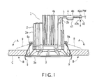
- FIG. 1 is a side view showing a downlight as the recessed luminaire
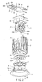
- FIG. 2 is an exploded perspective view of the downlight
- FIG. 3 is a partially sectioned side view of the same
- FIG. 4 is a top view of the same
- FIG. 6 is a bottom view of the same.
- a downlight main body 1 comprises a cylindrical body 2 which has a thermal conductivity, a decorative frame 3 and a terminal base attachment member 4 which are attached to the cylindrical body 2, a substrate 5 which is also attached to the cylindrical body 2 and on which LEDs (light-emitting devices) 10 as a light source are mounted, a power supply unit 6 including a power supply circuit board 20 contained in the cylindrical body 2, a reflector 7, and a translucent cover 8 attached in front of the reflector 7.
- the cylindrical body 2 is an aluminum die-casting product, which is formed of a material having a high thermal conductivity.
- the outer surface of the cylindrical body 2 is coated by baked finish with white melamine-based resin paint. As long as the thermal conductivity is assured, the cylindrical body 2 may be formed of any other material.
- the cylindrical body 2 contains the power supply unit 6.
- the power supply unit 6 comprises two power supply circuit boards 20a and 20b, and a board attachment plate 20c to which the power supply circuit boards 20a and 20b are attached. One end of the board attachment plate 20c is bent upward and constitutes a shielding wall 2b. Electric components 21, such as a controlling IC, a transformer and a capacitor, are mounted on the power supply circuit boards 20a and 20b.
- the power supply circuit boards 20a and 20b are inserted into the cylindrical body 2 from above. Then, a lid 22 is put on and screwed to the cylindrical body from above, so that the power supply circuit boards 20a and 20b are contained inside the cylindrical body 2 in a hermetically sealed state. In this state, the shielding wall 2b closes a cut portion 2d formed in a side wall of the cylindrical body 2.
- the power supply circuit board 20 is electrically connected to the substrate 5 on which the LEDs 10 are mounted, and includes a power supply circuit which turns on and off the LEDs 10.
- the outer surface of the cylindrical body 2 is provided with a plurality of radiating fins 2a extending vertically.
- the decorative frame 3 is made of ABS resin and substantially umbrella-shaped. It is broaden toward one end, which is open and provided with an annular flange 3a. The other end of the decorative frame 3 is attached to the cylindrical body 2.
- a pair of attaching torsion springs 9, facing each other, are attached to the outer surface of the decorative frame 3 as engaging means. In other words, the pair of attaching torsion springs 9 are spaced apart at 180 degrees in the circumferential direction on the outer surface of the decorative frame 3.
- Each of the attaching torsion springs 9 has an attachment portion at its distal end.
- the attachment portion has a bent shape, which is rectangular in the front view and substantially V-shaped in the side view.
- a pair of support walls 9a are projected from the outer surface of the decorative frame 3 and a shaft is inserted between the support walls 9a.
- a coil portion of the attaching torsion spring 9 is supported by the shaft. Normally, inward elastic force as shown in FIG. 1 with an arrow A is exerted on the attaching torsion springs 9.
- the attaching torsion springs 9 can be rotated about the coil portions by operating the attachment portions.
- the terminal base attachment member 4 is made of steel metal and has a substantially rectangular shape. It comprises an attachment portion 4a attached to the cylindrical body 2 and an extending portion 4b extending laterally from the cylindrical body 2.
- the terminal base attachment member 4 comprises a first end 52 fixed to the downlight main body 1 and a second end 53 located opposite to the first end 52.
- a substantially box-shaped terminal base 41 and a holder 42, both made of synthetic resin, are disposed on the lower surface of the extending portion 4b.
- the holder 42 is located in the second end 53.
- the terminal base attachment member 4 has bent portions 54 in peripheral portions thereof. The bent portions 54 project downward from the peripheral portions of the terminal base attachment member 4.
- the holder 42 is located in an edge portion of the extending portion 4b, and the terminal base 41 and the holder 42 are arranged in a line along the direction of extension of the extending portion 4b and fixed to the terminal base attachment member 4 by fixing means, such as screws.
- the terminal base 41 and the holder 42 are attached to the terminal base attachment member 4 so as to be arranged in a line along the direction in which the extending portion 4b is extending.
- the attachment portion 4a lies over the lid 22 and screwed thereto on top of the cylindrical body 2 (see FIG. 2 ).
- the shielding wall 2b faces the terminal base 41. This structure prevents the air around the terminal base 41 from flowing in the direction of extension of the terminal base attachment portion 4.
- the power supply unit 6 is connected to the terminal base 41 by lead wires L or the like. Further, power wires PW from a commercial power source are connected to the terminal base 41. Thus, power is supplied to the power supply unit 6 via the terminal base 41.
- the terminal base 41 has holes 51 through which the lead wires L are inserted. The holes 51 and the terminal base 41 faces the shielding wall 2b (see FIG. 1 ).
- the holder 42 holds the power wires PW so that the tensile force may not be exerted on the connecting portion between the terminal base 41 and the power wires PW.
- the holder 42 functions as a stopper against the tensile force of the power wires PW.
- the holder 42 comprises a main body piece 42a and a press piece 42b.
- the power wires PW arranged on the side of the main body piece 42a are held between the press piece 42b and the main body piece 42a by setting the press piece 42b to the main body piece 42a, as indicated by an arrow a in FIG. 1 .
- an expanding portion 42c is formed in one end portion of the main body piece 42a (see FIG. 4 ).
- the expanding portion 42c is sandwiched between the terminal base 41 and the lower surface of the extending portion 4b, when the terminal base 41 is attached to the lower surface of the extending portion 4b.
- One of the attaching torsion springs 9 is located in a position facing the lower surface of the terminal base attachment portion 4.
- the LEDs 10, as a light source, are mounted on the main surface of the substrate 5 by surface mount technology.
- the substrate 5 is formed of a substantially circular flat plate made of glass epoxy resin, and attached to the bottom wall 2c of the cylindrical body 2 in close contact with each other. Thus, the substrate 5 is thermally connected to the cylindrical body 2.
- ceramic or synthetic resin which has an excellent heat radiating property and high tolerance, is applicable.
- metal as the material of the substrate 5, it is preferable to apply aluminum or the like, which has high thermal conductivity and an excellent heat radiating property.
- the reflector 7 made of white polycarbonate, ASA resin or the like is disposed on the main surface of the substrate 5.
- the reflector 7 performs a function of individually distribution-controlling lights emitted from the LEDs 10 and efficiently radiating the lights.
- FIG. 7 is an explanatory view explaining the method of attachment.
- the power wires PW wired in a space above the ceiling are connected to the terminal base 41, and held by the holder 42.
- the power wires PW are wired on the lower surface of the extending portion 4b of the terminal base attachment member 4 along the direction of extension.
- the operator operates the attachment portions of the attaching torsion springs 9 as the engaging means with the hands to rotate and hold them against the elastic force thereof in the directions of arrows in the drawing (the directions of the arrows B in FIG. 1 ).
- the operator inclines the downlight main body 1 while supporting it, and inserts a distal end side of the extending portion 4b of the terminal base attachment member 4 into a hold H formed in the ceiling.
- the operator releases the hands from the attaching torsion springs 9 and pushes up the downlight main body 1.
- the attaching torsion springs 9 are recovered in the inward direction and brought into contact with the rear surface of the ceiling C.
- the elastic force causes the downlight main body 1 to rise and the flange 3a of the decorative frame 3 to be pressed against the circumferential edge of the hole H, thus attaching the downlight main body 1 to the surface of the ceiling C.
- the power wires PW are wired along the direction of extension of the extending portion 4b of the terminal base attachment member 4; that is, the power wires PW extend in the direction of insertion into the hole H. Therefore, the main body 1 can easily be inserted through the hole H. Further, since one of the attaching torsion springs 9 is located in the position facing the lower surface of the terminal base attachment member 4, the operator can insert the extending portion 4b of the terminal base attachment portion 4 into the hole H, while supporting the main body 1 and visually observing the extending portion 4b after rotating the attachment portion of this attaching torsion spring 9. Thus, the working efficiency can be increased.
- the downlight is out of balance.
- the downlight is supported by the attaching torsion spring 9 provided below the lower surface of the terminal base attachment member 4, the downlight can be kept in a stably attached state.
- a lighting circuit operates to supply the power to the substrate 5 and the LEDs 10 emit light.
- Most of the lights emitted from of the LEDs 10 directly pass through the translucent cover 8 and radiate forward, while some of the lights are reflected and distribution-controlled by reflecting surfaces of the reflector 7, then pass through the translucent cover 8 and radiate forward.
- heat generated from the LEDs 1 during this process is mostly transmitted from the rear surface of the substrate 5 to the bottom wall 2c of the cylindrical body 2, and then to the entire circumferential portion of the cylindrical body 2. The heat is dissipated during this transmission process.
- the terminal base attachment member 4 is made of steel metal and fire-resistant.
- the shielding wall 2b is provided on the circumferential wall of the cylindrical body 2, even if the terminal base 41 catches fire due to contact failure or the like, fire spread can be avoided.
- the shielding wall 2b blocks the air flow in the direction of extension of the terminal base attachment member 4 and can prevent fire from spreading.
- the shielding wall 2b can prevent fire from spreading to the power supply unit 6 or the like.
- the terminal base 41 is attached to the lower surface of the terminal base attachment member 4, it is covered with the terminal base attachment member 4 and protected from intrusion of dust or the like.
- fire spread due to overheating of the terminal base 41 or the like can be prevented, thereby increasing the degree of safety. Further, the downlight main body 1 can easily be.attached, so that the efficiency in work can be increased. In addition, the terminal base 41 is protected from intrusion of dust or the like.
- the present invention is not limited to the above embodiment, but may be modified variously without departing from the scope of the invention.
- three attaching torsion springs as the engaging means may be arranged apart from one another at 120 degrees in the circumferential direction on the outer surface of the decorative frame.
- the number of engaging means is not particularly limited.
- the engaging means is not limited to a spring, but any engaging means is applicable as long as it has a configuration that can support the luminaire to the attaching surface.
- the light source a LED, an incandescent lamp, a fluorescent lamp, a high intensity discharge lamp, etc. are applicable.
- the recessed luminaire is not limited to a downlight but may be an emergency light etc.
Landscapes
- Engineering & Computer Science (AREA)
- General Engineering & Computer Science (AREA)
- Microelectronics & Electronic Packaging (AREA)
- Power Engineering (AREA)
- Arrangement Of Elements, Cooling, Sealing, Or The Like Of Lighting Devices (AREA)
- Non-Portable Lighting Devices Or Systems Thereof (AREA)
Abstract
Description
- The present invention relates to a recessed luminaire adapted for use in a recessed state in a ceiling or the like.
- As disclosed in Jpn. Pat. Appln. KOKAI Publication No.
2006-172895 - However, in the conventional luminaire mentioned above, dust or moisture may intrude into the terminal base, and a short circuit or contact failure may occur. In such a case, the terminal base will be overheated to a high temperature. Particularly, if the terminal base is made of synthetic resin or the like, it may be melted or catch fire and the fire may spread to the apparatus main body.
- The present invention has been made in consideration of the above drawbacks of the conventional art, and an object of the present invention is to provide a safe recessed luminaire, in which a terminal base is mounted on a lower surface of a fire-resistant terminal base attachment member projecting from a side of the main body of the luminaire.
- To achieve the above object, a recessed luminaire according to an embodiment of the present invention comprises a main body including a light source; a terminal base attachment member, which is fire-resistant; and a terminal base connected to power wires, which are attached in parallel to a lower surface of the terminal base attachment member and extending in a direction of projection of the terminal base attachment member.
- According to the present invention as will be described below, terms have the following definitions and technical meanings, unless otherwise defined specifically. A recessed luminaire means an illumination apparatus, for example, a downlight or an emergency light, which is recessed in a ceiling or wall. A light source may be an LED, an incandescent lamp, a fluorescent lamp, a high intensity discharge lamp, etc., and is not limited to a specific type of light source.
- The present invention prevents the spread of fire resulting from, for example, overheating of the terminal base, so that a safe recessed luminaire can be provided. Further, the present invention prevents dust or the like from intruding into the terminal base.
- Further, the present invention prevents fire from spreading to the apparatus main body.
- Furthermore, the present invention allows the operator to attach the luminaire while visually observing an extending part of the terminal base attachment member after operating engaging means. Accordingly, the attachment operation can be efficiently performed.
- The invention can be more fully understood from the following detailed description when taken in conjunction with the accompanying drawings, in which:
-
FIG. 1 is a side view of a recessed luminaire according to an embodiment of the present invention; -
FIG. 2 is an exploded perspective view of the recessed luminaire; -
FIG. 3 is a partially sectioned side view of the recessed luminaire; -
FIG. 4 is a top view of the recessed luminaire; -
FIG. 5 is a sectional view of the terminal base as viewed from a shielding wall; -
FIG. 6 is a bottom view of the recessed luminaire; and -
FIG. 7 is an explanatory view explaining a method of attaching the recessed luminaire. - A recessed luminaire according to an embodiment of the present invention will be described below with reference to
FIGS. 1 to 6 .FIG. 1 is a side view showing a downlight as the recessed luminaire,FIG. 2 is an exploded perspective view of the downlight,FIG. 3 is a partially sectioned side view of the same,FIG. 4 is a top view of the same andFIG. 6 is a bottom view of the same. - The drawings show a recessed downlight as the recessed luminaire. A downlight
main body 1 comprises acylindrical body 2 which has a thermal conductivity, adecorative frame 3 and a terminalbase attachment member 4 which are attached to thecylindrical body 2, asubstrate 5 which is also attached to thecylindrical body 2 and on which LEDs (light-emitting devices) 10 as a light source are mounted, apower supply unit 6 including a powersupply circuit board 20 contained in thecylindrical body 2, areflector 7, and atranslucent cover 8 attached in front of thereflector 7. - The
cylindrical body 2 is an aluminum die-casting product, which is formed of a material having a high thermal conductivity. The outer surface of thecylindrical body 2 is coated by baked finish with white melamine-based resin paint. As long as the thermal conductivity is assured, thecylindrical body 2 may be formed of any other material. Thecylindrical body 2 contains thepower supply unit 6. Thepower supply unit 6 comprises two powersupply circuit boards board attachment plate 20c to which the powersupply circuit boards board attachment plate 20c is bent upward and constitutes ashielding wall 2b.Electric components 21, such as a controlling IC, a transformer and a capacitor, are mounted on the powersupply circuit boards supply circuit boards cylindrical body 2 from above. Then, alid 22 is put on and screwed to the cylindrical body from above, so that the powersupply circuit boards cylindrical body 2 in a hermetically sealed state. In this state, theshielding wall 2b closes acut portion 2d formed in a side wall of thecylindrical body 2. The powersupply circuit board 20 is electrically connected to thesubstrate 5 on which theLEDs 10 are mounted, and includes a power supply circuit which turns on and off theLEDs 10. The outer surface of thecylindrical body 2 is provided with a plurality of radiatingfins 2a extending vertically. - The
decorative frame 3 is made of ABS resin and substantially umbrella-shaped. It is broaden toward one end, which is open and provided with anannular flange 3a. The other end of thedecorative frame 3 is attached to thecylindrical body 2. A pair of attachingtorsion springs 9, facing each other, are attached to the outer surface of thedecorative frame 3 as engaging means. In other words, the pair of attachingtorsion springs 9 are spaced apart at 180 degrees in the circumferential direction on the outer surface of thedecorative frame 3. Each of the attachingtorsion springs 9 has an attachment portion at its distal end. The attachment portion has a bent shape, which is rectangular in the front view and substantially V-shaped in the side view. A pair ofsupport walls 9a are projected from the outer surface of thedecorative frame 3 and a shaft is inserted between thesupport walls 9a. A coil portion of the attachingtorsion spring 9 is supported by the shaft. Normally, inward elastic force as shown inFIG. 1 with an arrow A is exerted on the attachingtorsion springs 9. The attachingtorsion springs 9 can be rotated about the coil portions by operating the attachment portions. - The terminal
base attachment member 4 is made of steel metal and has a substantially rectangular shape. It comprises anattachment portion 4a attached to thecylindrical body 2 and an extendingportion 4b extending laterally from thecylindrical body 2. The terminalbase attachment member 4 comprises afirst end 52 fixed to the downlightmain body 1 and asecond end 53 located opposite to thefirst end 52. A substantially box-shaped terminal base 41 and aholder 42, both made of synthetic resin, are disposed on the lower surface of the extendingportion 4b. Theholder 42 is located in thesecond end 53. The terminalbase attachment member 4 has bentportions 54 in peripheral portions thereof. Thebent portions 54 project downward from the peripheral portions of the terminalbase attachment member 4. - As regards the location of the
terminal base 41 and theholder 42, theholder 42 is located in an edge portion of the extendingportion 4b, and theterminal base 41 and theholder 42 are arranged in a line along the direction of extension of the extendingportion 4b and fixed to the terminalbase attachment member 4 by fixing means, such as screws. In other words, theterminal base 41 and theholder 42 are attached to the terminalbase attachment member 4 so as to be arranged in a line along the direction in which the extendingportion 4b is extending. Further, theattachment portion 4a lies over thelid 22 and screwed thereto on top of the cylindrical body 2 (seeFIG. 2 ). - In the state where the terminal
base attachment member 4 is attached to thecylindrical body 2, the shieldingwall 2b faces theterminal base 41. This structure prevents the air around theterminal base 41 from flowing in the direction of extension of the terminalbase attachment portion 4. - The
power supply unit 6 is connected to theterminal base 41 by lead wires L or the like. Further, power wires PW from a commercial power source are connected to theterminal base 41. Thus, power is supplied to thepower supply unit 6 via theterminal base 41. As shown inFIG. 5 , theterminal base 41 hasholes 51 through which the lead wires L are inserted. Theholes 51 and theterminal base 41 faces the shieldingwall 2b (seeFIG. 1 ). When tensile force is applied to the power wires PW, theholder 42 holds the power wires PW so that the tensile force may not be exerted on the connecting portion between theterminal base 41 and the power wires PW. Thus, theholder 42 functions as a stopper against the tensile force of the power wires PW. More specifically, though not shown in the drawings in detail, theholder 42 comprises amain body piece 42a and apress piece 42b. The power wires PW arranged on the side of themain body piece 42a are held between thepress piece 42b and themain body piece 42a by setting thepress piece 42b to themain body piece 42a, as indicated by an arrow a inFIG. 1 . Further, an expandingportion 42c is formed in one end portion of themain body piece 42a (seeFIG. 4 ). The expandingportion 42c is sandwiched between theterminal base 41 and the lower surface of the extendingportion 4b, when theterminal base 41 is attached to the lower surface of the extendingportion 4b. One of the attaching torsion springs 9 is located in a position facing the lower surface of the terminalbase attachment portion 4. - The
LEDs 10, as a light source, are mounted on the main surface of thesubstrate 5 by surface mount technology. Thesubstrate 5 is formed of a substantially circular flat plate made of glass epoxy resin, and attached to thebottom wall 2c of thecylindrical body 2 in close contact with each other. Thus, thesubstrate 5 is thermally connected to thecylindrical body 2. In the case of using an insulating material as the material of thesubstrate 5, ceramic or synthetic resin, which has an excellent heat radiating property and high tolerance, is applicable. In the case of using metal as the material of thesubstrate 5, it is preferable to apply aluminum or the like, which has high thermal conductivity and an excellent heat radiating property. - The
reflector 7 made of white polycarbonate, ASA resin or the like is disposed on the main surface of thesubstrate 5. Thereflector 7 performs a function of individually distribution-controlling lights emitted from theLEDs 10 and efficiently radiating the lights. - A method of attaching the downlight having the aforementioned configurations to the ceiling will be described with reference to
FIG. 7. FIG. 7 is an explanatory view explaining the method of attachment. First the power wires PW wired in a space above the ceiling are connected to theterminal base 41, and held by theholder 42. In this state, the power wires PW are wired on the lower surface of the extendingportion 4b of the terminalbase attachment member 4 along the direction of extension. Then, the operator operates the attachment portions of the attachingtorsion springs 9 as the engaging means with the hands to rotate and hold them against the elastic force thereof in the directions of arrows in the drawing (the directions of the arrows B inFIG. 1 ). The operator inclines the downlightmain body 1 while supporting it, and inserts a distal end side of the extendingportion 4b of the terminalbase attachment member 4 into a hold H formed in the ceiling. As the downlightmain body 1 is being inserted in the hole H, the operator releases the hands from the attachingtorsion springs 9 and pushes up the downlightmain body 1. As a result, as indicated by broken lines inFIG. 1 , the attachingtorsion springs 9 are recovered in the inward direction and brought into contact with the rear surface of the ceiling C. The elastic force causes the downlightmain body 1 to rise and theflange 3a of thedecorative frame 3 to be pressed against the circumferential edge of the hole H, thus attaching the downlightmain body 1 to the surface of the ceiling C. - According to the attachment method described above, the power wires PW are wired along the direction of extension of the extending
portion 4b of the terminalbase attachment member 4; that is, the power wires PW extend in the direction of insertion into the hole H. Therefore, themain body 1 can easily be inserted through the hole H. Further, since one of the attaching torsion springs 9 is located in the position facing the lower surface of the terminalbase attachment member 4, the operator can insert the extendingportion 4b of the terminalbase attachment portion 4 into the hole H, while supporting themain body 1 and visually observing the extendingportion 4b after rotating the attachment portion of this attachingtorsion spring 9. Thus, the working efficiency can be increased. Furthermore, in the state where the downlightmain body 1 is attached to the ceiling, since the terminalbase attachment member 4 extends laterally from thecylindrical body 2, the downlight is out of balance. However, since the downlight is supported by the attachingtorsion spring 9 provided below the lower surface of the terminalbase attachment member 4, the downlight can be kept in a stably attached state. - In the configuration described above, when the
power supply unit 6 is turned on, a lighting circuit operates to supply the power to thesubstrate 5 and theLEDs 10 emit light. Most of the lights emitted from of theLEDs 10 directly pass through thetranslucent cover 8 and radiate forward, while some of the lights are reflected and distribution-controlled by reflecting surfaces of thereflector 7, then pass through thetranslucent cover 8 and radiate forward. On the other hand, heat generated from theLEDs 1 during this process is mostly transmitted from the rear surface of thesubstrate 5 to thebottom wall 2c of thecylindrical body 2, and then to the entire circumferential portion of thecylindrical body 2. The heat is dissipated during this transmission process. - While the downlight is being used, even if the
terminal base 41 is overheated to a high temperature for some reason and melts or catches fire, fire spread can be avoided, since the terminalbase attachment member 4 is made of steel metal and fire-resistant. Further, since the shieldingwall 2b is provided on the circumferential wall of thecylindrical body 2, even if theterminal base 41 catches fire due to contact failure or the like, fire spread can be avoided. In addition, the shieldingwall 2b blocks the air flow in the direction of extension of the terminalbase attachment member 4 and can prevent fire from spreading. Thus, the shieldingwall 2b can prevent fire from spreading to thepower supply unit 6 or the like. Furthermore, since theterminal base 41 is attached to the lower surface of the terminalbase attachment member 4, it is covered with the terminalbase attachment member 4 and protected from intrusion of dust or the like. - According to the embodiment described above, fire spread due to overheating of the
terminal base 41 or the like can be prevented, thereby increasing the degree of safety. Further, the downlightmain body 1 can easily be.attached, so that the efficiency in work can be increased. In addition, theterminal base 41 is protected from intrusion of dust or the like. - The present invention is not limited to the above embodiment, but may be modified variously without departing from the scope of the invention. For example, three attaching torsion springs as the engaging means may be arranged apart from one another at 120 degrees in the circumferential direction on the outer surface of the decorative frame. Thus, the number of engaging means is not particularly limited. The engaging means is not limited to a spring, but any engaging means is applicable as long as it has a configuration that can support the luminaire to the attaching surface. As the light source, a LED, an incandescent lamp, a fluorescent lamp, a high intensity discharge lamp, etc. are applicable. Further, the recessed luminaire is not limited to a downlight but may be an emergency light etc.
- It is explicitly stated that all features disclosed in the description and/or the claims are intended to be disclosed separately and independently from each other for the purpose of original disclosure as well as for the purpose of restricting the claimed invention independent of the composition of the features in the embodiments and/or the claims. It is explicitly stated that all value ranges or indications of groups of entities disclose every possible intermediate value or intermediate entity for the purpose of original disclosure as well as for the purpose of restricting the claimed invention, in particular as limits of value ranges.
Claims (5)
- A recessed luminaire characterized by comprising:a main body (1) comprising a light source (10);a terminal base attachment member (4), which is fire-resistant and which is fixed to the main body (1) at a first end (52) and extending laterally from the main body (1); anda terminal base (41), which is disposed on a lower surface of the terminal base attachment member (4) and to which power wires (PW) extending in parallel in a direction of extension of the terminal base attachment member (4) are connected.
- The recessed luminaire according to claim 1, characterized by further comprising a shielding wall (2b) which faces the terminal base (41) under the lower surface of the terminal base attachment member (4) and which is located between the terminal base (41) and the main body (1).
- The recessed luminaire according to claim 1 or 2, characterized by further comprising engaging means (9) respectively having attachment portions, the attachment portion of one of the engaging means (9) is located at a position facing the lower surface of the terminal base attachment member (4).
- The recessed luminaire according to any one of claims 1 to 3, characterized by further comprising a holder (42) which is provided at a second end (53) opposite to the first end (52) of the terminal base attachment member (4) and which holds the power wires (PW) connected to the terminal base (41).
- The recessed luminaire according to any one of claims 1 to 4, characterized in that the terminal base attachment member (4) comprises a bent portion (54), which is provided on a peripheral portion of the terminal base attachment member (4) and projects downward from the peripheral portion.
Applications Claiming Priority (1)
| Application Number | Priority Date | Filing Date | Title |
|---|---|---|---|
| JP2008300058A JP2010129227A (en) | 2008-11-25 | 2008-11-25 | Recessed illuminating device |
Publications (2)
| Publication Number | Publication Date |
|---|---|
| EP2189710A2 true EP2189710A2 (en) | 2010-05-26 |
| EP2189710A3 EP2189710A3 (en) | 2012-02-22 |
Family
ID=41719315
Family Applications (1)
| Application Number | Title | Priority Date | Filing Date |
|---|---|---|---|
| EP09014629A Withdrawn EP2189710A3 (en) | 2008-11-25 | 2009-11-24 | Recessed luminaire |
Country Status (4)
| Country | Link |
|---|---|
| US (1) | US20100128491A1 (en) |
| EP (1) | EP2189710A3 (en) |
| JP (1) | JP2010129227A (en) |
| CN (1) | CN101737689B (en) |
Cited By (1)
| Publication number | Priority date | Publication date | Assignee | Title |
|---|---|---|---|---|
| EP2442012A4 (en) * | 2009-06-10 | 2013-07-31 | Sharp Kk | Illumination device |
Families Citing this family (30)
| Publication number | Priority date | Publication date | Assignee | Title |
|---|---|---|---|---|
| JPH075172B2 (en) * | 1991-08-12 | 1995-01-25 | 株式会社ダイフク | Goods sorting equipment |
| US8388166B2 (en) | 2007-10-24 | 2013-03-05 | Lsi Industries, Inc. | Lighting apparatus with a boost |
| JP5391767B2 (en) | 2008-05-30 | 2014-01-15 | 東芝ライテック株式会社 | Light emitting device and lighting apparatus |
| US8491163B2 (en) * | 2009-09-25 | 2013-07-23 | Toshiba Lighting & Technology Corporation | Lighting apparatus |
| JP5467547B2 (en) * | 2010-03-05 | 2014-04-09 | パナソニック株式会社 | lighting equipment |
| CN201897157U (en) * | 2010-10-27 | 2011-07-13 | 武良举 | Fireproof lamp |
| CN102889476A (en) * | 2011-07-19 | 2013-01-23 | 大连创达技术交易市场有限公司 | LED (light-emitting diode) down lamp |
| US20130100650A1 (en) * | 2011-10-24 | 2013-04-25 | Lumenoptix, Llc | Downlight led retrofit kit |
| USD687588S1 (en) * | 2011-11-30 | 2013-08-06 | Hamid Rashidi | Recessed lighting fixture with heat sink incorporating friction fit friction blades with baffle trim |
| USD687587S1 (en) * | 2011-11-30 | 2013-08-06 | Hamid Rashidi | Recessed lighting fixture with heat sink incorporating friction fit friction blades with baffle trim |
| USD695941S1 (en) * | 2011-11-30 | 2013-12-17 | Hamid Rashidi | Recessed lighting fixture with heat sink incorporating friction fit friction blades with reflector trim |
| USD698067S1 (en) * | 2011-11-30 | 2014-01-21 | Hamid Rashidi | Recessed lighting fixture with heat sink incorporating friction fit friction blades with reflector trim |
| DE202012003725U1 (en) * | 2012-03-28 | 2012-06-05 | Iventum Gmbh | lamp |
| USD679044S1 (en) * | 2012-04-09 | 2013-03-26 | Osram Sylvania Inc. | Recessed downlight |
| US9739455B2 (en) | 2012-04-17 | 2017-08-22 | Abl Ip Holding Llc | LED light engines |
| KR101248155B1 (en) * | 2012-04-17 | 2013-04-03 | (주)알텍테크놀로지스 | Embedded Lighting |
| CN103363408B (en) * | 2013-04-26 | 2016-08-10 | 佛山市威得士灯饰电器有限公司 | Ceiling lamp |
| GB201407301D0 (en) * | 2014-04-25 | 2014-06-11 | Aurora Ltd | Improved led lamps and luminaires |
| USD769501S1 (en) | 2014-05-22 | 2016-10-18 | Ledvance Llc | Recessed downlight luminaire |
| USD762906S1 (en) | 2014-05-22 | 2016-08-02 | Osram Sylvania Inc. | Recessed downlight luminaire |
| USD762907S1 (en) | 2014-05-23 | 2016-08-02 | Osram Sylvania Inc. | Recessed downlight gimbal luminaire |
| JP6138204B2 (en) * | 2015-04-28 | 2017-05-31 | 三菱電機株式会社 | Power unit for lighting and lighting device |
| JP6045662B2 (en) * | 2015-04-28 | 2016-12-14 | 三菱電機株式会社 | Power unit for lighting and lighting device |
| US9803814B2 (en) * | 2015-09-02 | 2017-10-31 | O'ryan Industries, Inc. | Lighting housing assembly |
| CA3018781A1 (en) * | 2016-03-21 | 2017-09-28 | Hubbell Incorporated | Light fixture with narrow light distribution |
| US20180058668A1 (en) * | 2016-08-31 | 2018-03-01 | Philips Lighting Holding B.V. | Captive retaining spring |
| DE102016116363A1 (en) * | 2016-09-01 | 2018-03-01 | Abb Ag | Installation device for ceiling mounting |
| US20190368671A1 (en) * | 2018-06-04 | 2019-12-05 | Lauren Illumination, Llc | Recessed mount for luminaire |
| US11754237B2 (en) | 2021-06-12 | 2023-09-12 | Lucifer Lighting Company | Retention, adjustability and maintenance for a recessed component such as a recessed luminaire |
| WO2022261546A2 (en) | 2021-06-12 | 2022-12-15 | Lucifer Lighting Company | Retention, adjustability and maintenance for a recessed component such as a recessed luminaire |
Citations (3)
| Publication number | Priority date | Publication date | Assignee | Title |
|---|---|---|---|---|
| DE3917788A1 (en) * | 1988-06-10 | 1989-12-14 | Wila Leuchten Gmbh | Installation box with accessory parts for low-voltage luminaires |
| JP2006172895A (en) | 2004-12-15 | 2006-06-29 | Matsushita Electric Works Ltd | lighting equipment |
| GB2471929A (en) * | 2009-07-17 | 2011-01-19 | Jcc Lighting Products Ltd | An intumescent electrical fitting |
Family Cites Families (60)
| Publication number | Priority date | Publication date | Assignee | Title |
|---|---|---|---|---|
| US3539801A (en) * | 1967-04-03 | 1970-11-10 | Mitchell Bobrick | Light fixture |
| US4254453A (en) * | 1978-08-25 | 1981-03-03 | General Instrument Corporation | Alpha-numeric display array and method of manufacture |
| US4400673A (en) * | 1981-12-21 | 1983-08-23 | Kiddo Consumer Durables Corporation | Thermal switch housing |
| US4641222A (en) * | 1984-05-29 | 1987-02-03 | Motorola, Inc. | Mounting system for stress relief in surface mounted components |
| US5400229A (en) * | 1994-06-08 | 1995-03-21 | Formosa Industrial Computing, Inc. | Receptacle apparatus for light emitting diodes |
| US5519596A (en) * | 1995-05-16 | 1996-05-21 | Hewlett-Packard Company | Moldable nesting frame for light emitting diode array |
| JPH09282912A (en) * | 1996-04-17 | 1997-10-31 | Matsushita Electric Works Ltd | Luminaire |
| JPH09312357A (en) * | 1996-05-21 | 1997-12-02 | Fuji Electric Co Ltd | Semiconductor device |
| US7047607B2 (en) * | 1996-12-30 | 2006-05-23 | Wattex | Process for manufacturing a band-shaped non-woven product with increased tensile strength |
| US6552658B1 (en) * | 1997-10-17 | 2003-04-22 | Truck Lite Co | Light emitting diode flashing directional warning lamp |
| JP3591285B2 (en) * | 1998-03-26 | 2004-11-17 | 松下電工株式会社 | lighting equipment |
| US6498708B2 (en) * | 1999-05-27 | 2002-12-24 | Emerson Electric Co. | Method and apparatus for mounting printed circuit board components |
| US6367949B1 (en) * | 1999-08-04 | 2002-04-09 | 911 Emergency Products, Inc. | Par 36 LED utility lamp |
| JP3445949B2 (en) * | 1999-11-17 | 2003-09-16 | 朝日松下電工株式会社 | Lighting device |
| DE10012734C1 (en) * | 2000-03-16 | 2001-09-27 | Bjb Gmbh & Co Kg | Illumination kit for illumination, display or notice purposes has plug connector with contacts in row along edge of each light emitting module to mechanically/electrically connect modules |
| US6641284B2 (en) * | 2002-02-21 | 2003-11-04 | Whelen Engineering Company, Inc. | LED light assembly |
| CA2373874C (en) * | 2002-02-28 | 2007-10-02 | Canlyte Inc. | Light fixture assembly |
| JP3864819B2 (en) * | 2002-03-19 | 2007-01-10 | 松下電工株式会社 | Lighting equipment for fluorescent lamps |
| US6840654B2 (en) * | 2002-11-20 | 2005-01-11 | Acolyte Technologies Corp. | LED light and reflector |
| CN2639704Y (en) * | 2003-09-01 | 2004-09-08 | 东莞市星锐灯饰有限公司 | Lamp structure |
| US7018070B2 (en) * | 2003-09-12 | 2006-03-28 | Dekko Technologies, Inc. | Fluorescent lampholder with disconnectable plug on back |
| US7281818B2 (en) * | 2003-12-11 | 2007-10-16 | Dialight Corporation | Light reflector device for light emitting diode (LED) array |
| JP4419059B2 (en) * | 2004-02-12 | 2010-02-24 | 東芝ライテック株式会社 | Recessed ceiling lighting fixture |
| US7357541B2 (en) * | 2004-04-05 | 2008-04-15 | Genlyte Thomas Group, Llc | Enclosure for socket cup for snap-in electrical quick connectors |
| DE102004051449A1 (en) * | 2004-10-22 | 2006-04-27 | Thompson, Choy Wing Chee, Pat Heung | Luminaire and method for changing a light source |
| US7207695B2 (en) * | 2004-11-22 | 2007-04-24 | Osram Sylvania Inc. | LED lamp with LEDs on a heat conductive post and method of making the LED lamp |
| DE102004062989A1 (en) * | 2004-12-22 | 2006-07-06 | Patent-Treuhand-Gesellschaft für elektrische Glühlampen mbH | Lighting device with at least one light emitting diode and vehicle headlights |
| JP2006185602A (en) * | 2004-12-24 | 2006-07-13 | Toshiba Lighting & Technology Corp | Recessed ceiling fixtures and recessed ceiling lighting fixtures |
| JP2006260986A (en) * | 2005-03-17 | 2006-09-28 | Koowa:Kk | Recessed ceiling lighting fixture |
| US7918591B2 (en) * | 2005-05-13 | 2011-04-05 | Permlight Products, Inc. | LED-based luminaire |
| GB0510494D0 (en) * | 2005-05-23 | 2005-06-29 | Aurora Ltd | Improvements to fire related downlights |
| JP2007059072A (en) * | 2005-08-22 | 2007-03-08 | Mitsubishi Electric Corp | Terminal block and lighting fixture provided with the terminal block |
| US7303310B2 (en) * | 2006-03-23 | 2007-12-04 | Opto Tech Corp. | Structure for a high efficiency and water-proof lighting device |
| US7549772B2 (en) * | 2006-03-31 | 2009-06-23 | Pyroswift Holding Co., Limited | LED lamp conducting structure with plate-type heat pipe |
| US7494249B2 (en) * | 2006-07-05 | 2009-02-24 | Jaffe Limited | Multiple-set heat-dissipating structure for LED lamp |
| US7738235B2 (en) * | 2006-07-31 | 2010-06-15 | B/E Aerospace, Inc. | LED light apparatus |
| TW200837308A (en) * | 2006-09-21 | 2008-09-16 | Led Lighting Fixtures Inc | Lighting assemblies, methods of installing same, and methods of replacing lights |
| JP4853278B2 (en) * | 2006-12-25 | 2012-01-11 | パナソニック電工株式会社 | Lighting device |
| US7473011B2 (en) * | 2007-05-04 | 2009-01-06 | Ruud Lighting, Inc. | Method and apparatus for mounting an LED module to a heat sink assembly |
| CN101680638B (en) * | 2007-05-07 | 2015-07-29 | 科锐公司 | Lamp fitting |
| US7677766B2 (en) * | 2007-05-07 | 2010-03-16 | Lsi Industries, Inc. | LED lamp device and method to retrofit a lighting fixture |
| US8333490B2 (en) * | 2007-07-05 | 2012-12-18 | Liangju Wu | Fireproof light fixture |
| CN201072101Y (en) * | 2007-07-05 | 2008-06-11 | 武良举 | Barrel-type fireproof lamp |
| US7665866B2 (en) * | 2007-07-16 | 2010-02-23 | Lumination Llc | LED luminaire for generating substantially uniform illumination on a target plane |
| US7914162B1 (en) * | 2007-08-23 | 2011-03-29 | Grand General Accessories Manufacturing | LED light assembly having heating board |
| USD595452S1 (en) * | 2007-10-10 | 2009-06-30 | Cordelia Lighting, Inc. | Recessed baffle trim |
| CN101413652B (en) * | 2007-10-16 | 2010-11-10 | 富士迈半导体精密工业(上海)有限公司 | Light-emitting diode light source device |
| US7866850B2 (en) * | 2008-02-26 | 2011-01-11 | Journée Lighting, Inc. | Light fixture assembly and LED assembly |
| TWI419357B (en) * | 2008-03-12 | 2013-12-11 | Bright Led Electronics Corp | Manufacturing method of light emitting module |
| CN101545614B (en) * | 2008-03-26 | 2012-05-23 | 富准精密工业(深圳)有限公司 | LED fixture |
| CN101556032B (en) * | 2008-04-09 | 2010-09-29 | 富准精密工业(深圳)有限公司 | LED lamps |
| US8011809B2 (en) * | 2008-05-16 | 2011-09-06 | Yun Chang Liao | Light-emitting diode module with heat dissipating structure and lamp with light-emitting diode module |
| US7845829B2 (en) * | 2008-05-20 | 2010-12-07 | Abl Ip Holding Llc | Enclosures for LED circuit boards |
| US7824077B2 (en) * | 2008-06-30 | 2010-11-02 | Che-Kai Chen | Lamp structure |
| JP5077693B2 (en) * | 2008-08-28 | 2012-11-21 | 東芝ライテック株式会社 | lighting equipment |
| US7832909B2 (en) * | 2008-10-08 | 2010-11-16 | Ceramate Technical Co., Ltd. | Combinational inset lamp exempt from a shielding cylinder |
| EP2180241B1 (en) * | 2008-10-22 | 2012-08-29 | Toshiba Lighting & Technology Corporation | Lighting Apparatus |
| US7717590B1 (en) * | 2008-11-07 | 2010-05-18 | Chia-Mao Li | LED lamp with reflecting casings |
| US8602601B2 (en) * | 2009-02-11 | 2013-12-10 | Koninklijke Philips N.V. | LED downlight retaining ring |
| US9068719B2 (en) * | 2009-09-25 | 2015-06-30 | Cree, Inc. | Light engines for lighting devices |
-
2008
- 2008-11-25 JP JP2008300058A patent/JP2010129227A/en active Pending
-
2009
- 2009-11-24 US US12/624,958 patent/US20100128491A1/en not_active Abandoned
- 2009-11-24 CN CN2009102236906A patent/CN101737689B/en not_active Expired - Fee Related
- 2009-11-24 EP EP09014629A patent/EP2189710A3/en not_active Withdrawn
Patent Citations (3)
| Publication number | Priority date | Publication date | Assignee | Title |
|---|---|---|---|---|
| DE3917788A1 (en) * | 1988-06-10 | 1989-12-14 | Wila Leuchten Gmbh | Installation box with accessory parts for low-voltage luminaires |
| JP2006172895A (en) | 2004-12-15 | 2006-06-29 | Matsushita Electric Works Ltd | lighting equipment |
| GB2471929A (en) * | 2009-07-17 | 2011-01-19 | Jcc Lighting Products Ltd | An intumescent electrical fitting |
Cited By (2)
| Publication number | Priority date | Publication date | Assignee | Title |
|---|---|---|---|---|
| EP2442012A4 (en) * | 2009-06-10 | 2013-07-31 | Sharp Kk | Illumination device |
| US8770781B2 (en) | 2009-06-10 | 2014-07-08 | Sharp Kabushiki Kaisha | Lighting apparatus |
Also Published As
| Publication number | Publication date |
|---|---|
| CN101737689A (en) | 2010-06-16 |
| JP2010129227A (en) | 2010-06-10 |
| CN101737689B (en) | 2012-07-04 |
| US20100128491A1 (en) | 2010-05-27 |
| EP2189710A3 (en) | 2012-02-22 |
Similar Documents
| Publication | Publication Date | Title |
|---|---|---|
| US20100128491A1 (en) | Recessed luminaire | |
| JP4798504B2 (en) | lighting equipment | |
| JP5182634B2 (en) | lighting equipment | |
| JP5655950B2 (en) | Lamps and lighting fixtures | |
| US8550669B2 (en) | Adjustable slope ceiling recessed light fixture | |
| JP4807631B2 (en) | lighting equipment | |
| JP6251081B2 (en) | Reflection unit and LED module | |
| JP4671064B2 (en) | lighting equipment | |
| JP5946008B2 (en) | lighting equipment | |
| JP4756391B2 (en) | lighting equipment | |
| JP6046878B2 (en) | Lamp apparatus and lighting apparatus | |
| JP4636342B2 (en) | lighting equipment | |
| JP4756383B2 (en) | lighting equipment | |
| JP2012160264A (en) | Lighting fixture | |
| JP6011765B2 (en) | LED lighting fixtures | |
| CN204460021U (en) | Lighting device | |
| JP2013118198A (en) | Illumination apparatus | |
| JP2013008582A (en) | Lamp device | |
| JP6569896B2 (en) | LED lighting device and lighting fixture | |
| JP5888624B2 (en) | lighting equipment | |
| JP6436665B2 (en) | Lighting equipment and emergency lighting equipment | |
| JP6274458B2 (en) | lighting equipment | |
| JP6191894B2 (en) | lighting equipment | |
| JP5888623B2 (en) | lighting equipment | |
| JP2017183066A (en) | Light source unit, light source device, and lighting device |
Legal Events
| Date | Code | Title | Description |
|---|---|---|---|
| PUAI | Public reference made under article 153(3) epc to a published international application that has entered the european phase |
Free format text: ORIGINAL CODE: 0009012 |
|
| 17P | Request for examination filed |
Effective date: 20091124 |
|
| AK | Designated contracting states |
Kind code of ref document: A2 Designated state(s): AT BE BG CH CY CZ DE DK EE ES FI FR GB GR HR HU IE IS IT LI LT LU LV MC MK MT NL NO PL PT RO SE SI SK SM TR |
|
| AX | Request for extension of the european patent |
Extension state: AL BA RS |
|
| PUAL | Search report despatched |
Free format text: ORIGINAL CODE: 0009013 |
|
| AK | Designated contracting states |
Kind code of ref document: A3 Designated state(s): AT BE BG CH CY CZ DE DK EE ES FI FR GB GR HR HU IE IS IT LI LT LU LV MC MK MT NL NO PL PT RO SE SI SK SM TR |
|
| AX | Request for extension of the european patent |
Extension state: AL BA RS |
|
| RIC1 | Information provided on ipc code assigned before grant |
Ipc: F21V 23/02 20060101ALI20120117BHEP Ipc: F21V 29/00 20060101ALI20120117BHEP Ipc: F21Y 101/02 20060101ALI20120117BHEP Ipc: F21S 8/02 20060101ALI20120117BHEP Ipc: F21V 25/12 20060101ALI20120117BHEP Ipc: F21V 21/04 20060101AFI20120117BHEP |
|
| 17Q | First examination report despatched |
Effective date: 20130704 |
|
| STAA | Information on the status of an ep patent application or granted ep patent |
Free format text: STATUS: THE APPLICATION IS DEEMED TO BE WITHDRAWN |
|
| 18D | Application deemed to be withdrawn |
Effective date: 20131115 |