EP2189598B1 - Système d'accès à un bâtiment - Google Patents
Système d'accès à un bâtiment Download PDFInfo
- Publication number
- EP2189598B1 EP2189598B1 EP08169369.9A EP08169369A EP2189598B1 EP 2189598 B1 EP2189598 B1 EP 2189598B1 EP 08169369 A EP08169369 A EP 08169369A EP 2189598 B1 EP2189598 B1 EP 2189598B1
- Authority
- EP
- European Patent Office
- Prior art keywords
- signal
- emergency
- building
- key
- antenna
- Prior art date
- Legal status (The legal status is an assumption and is not a legal conclusion. Google has not performed a legal analysis and makes no representation as to the accuracy of the status listed.)
- Active
Links
- 230000006854 communication Effects 0.000 claims description 54
- 238000004891 communication Methods 0.000 claims description 54
- 230000033001 locomotion Effects 0.000 claims description 30
- 238000004590 computer program Methods 0.000 claims description 26
- 238000012360 testing method Methods 0.000 claims description 25
- 230000004913 activation Effects 0.000 claims description 23
- 239000000779 smoke Substances 0.000 claims description 14
- 238000004458 analytical method Methods 0.000 claims description 11
- 238000013475 authorization Methods 0.000 claims description 10
- 230000002596 correlated effect Effects 0.000 claims description 9
- 230000005540 biological transmission Effects 0.000 claims description 7
- 239000011521 glass Substances 0.000 claims description 5
- 238000000034 method Methods 0.000 claims description 5
- 238000005034 decoration Methods 0.000 claims 1
- 230000008901 benefit Effects 0.000 description 19
- 238000001514 detection method Methods 0.000 description 6
- 238000010191 image analysis Methods 0.000 description 6
- 241000219739 Lens Species 0.000 description 4
- 230000006378 damage Effects 0.000 description 4
- 239000000446 fuel Substances 0.000 description 4
- 210000004379 membrane Anatomy 0.000 description 4
- 230000003287 optical effect Effects 0.000 description 4
- 230000035945 sensitivity Effects 0.000 description 3
- 229910000831 Steel Inorganic materials 0.000 description 2
- 230000008859 change Effects 0.000 description 2
- 230000000295 complement effect Effects 0.000 description 2
- 230000002427 irreversible effect Effects 0.000 description 2
- 239000012528 membrane Substances 0.000 description 2
- 229910044991 metal oxide Inorganic materials 0.000 description 2
- 150000004706 metal oxides Chemical class 0.000 description 2
- 208000010125 myocardial infarction Diseases 0.000 description 2
- 239000005445 natural material Substances 0.000 description 2
- 239000002245 particle Substances 0.000 description 2
- 239000004033 plastic Substances 0.000 description 2
- 230000005855 radiation Effects 0.000 description 2
- 239000004065 semiconductor Substances 0.000 description 2
- 229910001220 stainless steel Inorganic materials 0.000 description 2
- 239000010935 stainless steel Substances 0.000 description 2
- 239000010959 steel Substances 0.000 description 2
- 208000000059 Dyspnea Diseases 0.000 description 1
- 206010013975 Dyspnoeas Diseases 0.000 description 1
- 240000004322 Lens culinaris Species 0.000 description 1
- 206010038687 Respiratory distress Diseases 0.000 description 1
- 230000007175 bidirectional communication Effects 0.000 description 1
- 230000002457 bidirectional effect Effects 0.000 description 1
- 230000036772 blood pressure Effects 0.000 description 1
- 239000003086 colorant Substances 0.000 description 1
- 238000010276 construction Methods 0.000 description 1
- 230000008878 coupling Effects 0.000 description 1
- 238000010168 coupling process Methods 0.000 description 1
- 238000005859 coupling reaction Methods 0.000 description 1
- 238000013500 data storage Methods 0.000 description 1
- 230000001419 dependent effect Effects 0.000 description 1
- 238000011161 development Methods 0.000 description 1
- 230000018109 developmental process Effects 0.000 description 1
- 230000000694 effects Effects 0.000 description 1
- 230000005611 electricity Effects 0.000 description 1
- 230000006870 function Effects 0.000 description 1
- 238000009434 installation Methods 0.000 description 1
- 206010025482 malaise Diseases 0.000 description 1
- 238000005259 measurement Methods 0.000 description 1
- 230000002265 prevention Effects 0.000 description 1
- 230000004044 response Effects 0.000 description 1
- 208000013220 shortness of breath Diseases 0.000 description 1
- 210000002023 somite Anatomy 0.000 description 1
- 238000001228 spectrum Methods 0.000 description 1
- 230000003068 static effect Effects 0.000 description 1
- 239000002023 wood Substances 0.000 description 1
Images


Classifications
-
- G—PHYSICS
- G07—CHECKING-DEVICES
- G07C—TIME OR ATTENDANCE REGISTERS; REGISTERING OR INDICATING THE WORKING OF MACHINES; GENERATING RANDOM NUMBERS; VOTING OR LOTTERY APPARATUS; ARRANGEMENTS, SYSTEMS OR APPARATUS FOR CHECKING NOT PROVIDED FOR ELSEWHERE
- G07C9/00—Individual registration on entry or exit
- G07C9/00174—Electronically operated locks; Circuits therefor; Nonmechanical keys therefor, e.g. passive or active electrical keys or other data carriers without mechanical keys
- G07C9/00182—Electronically operated locks; Circuits therefor; Nonmechanical keys therefor, e.g. passive or active electrical keys or other data carriers without mechanical keys operated with unidirectional data transmission between data carrier and locks
Definitions
- the invention relates to an access system to a building according to the preamble of claim 1.
- the DIN 14675 prescribes to set up a fire department key depository at the entrance to a building, which fire department key deposit consists of a sturdy box which can be opened with a fire department key. Only the fire department has this fire department key. In the fire department key deposit is an emergency key, with which the fire brigade has at any time a rapid and non-violent access to the building.
- the document EP1088958A discloses a key box with an interior in which some keys are kept.
- the interior is accessible via two doors connected in series, an interior door and an outside door.
- the outer door is unlocked by a monitoring center, while the inner door has a code lock.
- the document DE102004041518A1 discloses a lock cylinder for installation in a lock, with a closing member for actuating a lock bolt or the like and an actuator, wherein the actuator is normally decoupled from the closing member, and with a coupling for connecting the closing member with the actuator after receiving an identification code of a assigned transponder.
- the object of the present invention is to further develop this access system.
- the invention relates to an access system to a building.
- At least one key pocket is publicly accessible in at least one area of the building.
- the key compartment has at least one key for at least one building door and which key is accessible by removing at least one closure.
- the key stores at least one identification code.
- the building door has at least one transmitting / receiving device.
- the transmission / reception apparatus receives the identification code of the key.
- At least one tester checks to see if at least one valid one for the received identification code Access authorization to the building door exists; and that if a valid access authorization to the building door exists for the received identification code, at least one locking device unlocks the building door.
- At least one antenna of the transceiver generates at least one local radio field.
- the detection range of the antenna of the transceiver is limited to a radius of a few centimeters to a few meters.
- the key is a passive radio card for radio frequency identification.
- the passive radio card has at least one coil and at least one computer-readable data memory; the identification code is stored in the computer-readable data memory; as soon as the passive radio card is in the local radio field, the coil inductively absorbs energy in the local radio field and the passive radio card is energetically activated; the energetically activated passive radio card reads the identification code from the computer-readable data memory; and the coil of the energetically activated passive radio card sends the read identification code in the local radio field to the antenna of the transceiver.
- the key is an active radio card for a radio network such as Bluetooth and / or ZigBee and / or Wi-Fi.
- the active radio card has at least one antenna and at least one computer-readable data memory and at least one electrical power supply; the identification code is stored in the computer-readable data memory; as soon as the active radio card is in the local radio field, the active radio card reads the identification code from the computer-readable data memory and the antenna sends the active radio card the read identification code in the local radio field to the antenna of the transceiver.
- At least one emergency sensor detects at least one area of the building as at least one signal detected.
- the emergency sensor is a camera and / or a switch and / or a smoke detector and / or a motion detector.
- the signal meets at least one condition for an emergency signal when a person stays in an area of the building for an extended period of time.
- the signal meets at least one condition for an emergency signal when a person is lying on a floor of the building for an extended period of time.
- the signal meets at least one condition for an emergency signal when a person is lying on a floor of the building for an extended period of time and does not move.
- the signal meets at least one condition for an emergency signal when a person lies on a floor of the building for an extended period of time and beckons with at least one hand.
- the signal meets at least one condition for an emergency signal when a person moves at a certain speed in the building.
- the signal meets at least one condition for an emergency signal when the switch detects the signal for a given, freely adjustable duration.
- the signal fulfills at least one condition for an emergency signal if the switch detects as a signal a specific, freely adjustable pressure of at least 2.5 newton, preferably at least five newton, preferably at least ten newton.
- the signal fulfills at least one condition for an emergency signal when a detected signal exceeds at least one freely adjustable threshold value.
- the signal fulfills at least one condition for an emergency signal when the motion detector detects as a signal a movement in a certain period of time in at least one area of the building.
- the signal fulfills at least one condition for an emergency signal when the motion detector detects a signal as a movement over a longer period in at least one area of the building.
- the signal fulfills at least one condition for an emergency signal when the motion detector detects as a signal a movement at a certain speed in the building.
- the emergency sensor communicates with at least one center.
- the emergency sensor has at least one antenna; at least one control device of at least one central unit has at least one antenna; and the antenna of the emergency sensor transmits at least one signal and / or emergency signal to the antenna of the control device in at least one local radio network.
- at least one adapter of the emergency sensor communicates via at least one fixed network with at least one adapter of at least one control device of at least one control center; and the adapter of the emergency sensor transmits in the fixed network at least one signal and / or emergency signal to the adapter of the control device.
- the emergency sensor analyzes whether at least one condition for an emergency signal is fulfilled.
- at least one control device of the central unit analyzes whether at least one condition for an emergency signal has been fulfilled.
- the emergency sensor if a condition for an emergency signal is met, alerts at least one emergency service; and at least alerting an emergency service includes at least an indication of the location and / or time of an emergency in the building correlated with the emergency signal.
- the alarming of the emergency service includes at least one transmission of at least one emergency signal correlated with the emergency in the building to the emergency service.
- the emergency sensor communicates in at least one local radio network with at least one control center; at least one amplifier has at least one antenna; and the antenna of the amplifier amplifies the communication in the local radio network.
- the emergency sensor communicates at least one signal and / or emergency signal to at least one control center; and the central office communicates at least one activation signal to the key compartment for a communicated emergency signal.
- at least one control device of at least one control center has at least one antenna; at least one communication device of the key compartment has at least one antenna; and the antenna of the control device transmits at least one activation signal to the antenna of the communication device of the key compartment for an emergency signal in at least one local radio network.
- the emergency sensor communicates at least one signal and / or emergency signal to at least one control center; the central communicates at least one activation signal to the key compartment for a communicated emergency signal; and at least one locking device of the key compartment closes the shutter for a communicated activation signal.
- the central office communicates with the key compartment in at least one local radio network; at least one amplifier has at least one antenna; and the antenna of the amplifier amplifies the communication in the local radio network.
- the key compartment has at least one sabotage sensor; the sabotage sensor detects at least one removal of the closure; and the sabotage sensor generates at least one sabotage signal for a detected removal of the shutter.
- the sabotage sensor transmits the sabotage signal to the communication device via at least one signal line.
- the communication device communicates the sabotage signal to the center.
- the center receives the sabotage signal; at least one control device of the center compares whether at least one emergency signal exists for the received sabotage signal; and that if there is no emergency, the received sabotage signal controller alerts at least one emergency service.
- at least one alarm of the emergency service includes at least one indication of the location and / or time of sabotage correlated with the sabotage signal on the key compartment.
- the transmitting / receiving device is arranged in at least one door set.
- the test device is arranged in at least one door fitting.
- the locking device is arranged in at least one door set.
- the transceiver is at least one printed circuit board.
- the test device is at least one printed circuit board.
- the locking device has at least one latch, which latch can be moved back and forth by at least one motor between a locking position and an open position.
- the test apparatus if there is a valid access authorization to the building door for the received identification code, the test apparatus generates at least one positive test signal; the locking device has at least one latch, which latch can be moved back and forth by at least one motor between a locking position and an open position; the test device transmits the positive test signal to the locking device; and the locking device controls for a transmitted positive test signal to the motor so that the bolt moves back from the locked position to the open position.
- At least one electrical power supply is arranged in at least one door fitting.
- the electrical power supply is electrically self-sufficient.
- the electrical power supply supplies the transceiver with electrical power.
- the electrical power supply the tester with electrical power.
- the electrical power supply supplies the locking device with electric current.
- the key compartment has at least one main body.
- the base body is stably fixed in the area of the building.
- the closure closes at least one interior of the key compartment.
- the closure has at least one closing device.
- the closing device can be closed with at least one closing plate of the main body.
- the closing device has at least one bolt, which bolt can be moved out and back by at least one mechanical key between a closed position and an open position.
- the closing device has at least one bolt, which bolt can be moved out and back by at least one motor between a closed position and an open position. For at least one activated activation signal, the motor advantageously returns the bolt to an open position, which closure can be removed in the open position for a bolt.
- the center communicates at least one activation signal to the key compartment; and the motor retracts the bolt to an open position for at least one activated activation signal, which latch is removable for a bolt in the open position.
- the key compartment has at least one communication device with at least one antenna; at least one central unit has at least one control device with at least one antenna; the antenna of the control device transmits at least one activation signal to the antenna of the communication device in at least one local radio network; and the motor retracts the bolt to an open position for at least one transmitted activation signal, which latch is removable for a bolt in the open position.
- the closure is at least partially made of glass; and the closure can only be removed by irreversible damage or destruction of the closure.
- the key compartment has at least one communication device with at least one antenna in at least one interior space; which communication device is at least one printed circuit board.
- At least one electrical power supply is arranged in the key compartment; which electrical power supply is electrically self-sufficient.
- the electrical power supply supplies the closing device with electric current.
- a computer program product comprises at least one computer program means which is suitable for implementing the method for operating an access system by carrying out at least one method step if the computer program means in at least one processor at least one transceiver and / or at least a test device and / or at least one key and / or at least one control device and / or at least one communication device is loaded.
- the computer-readable data memory comprises such a computer program product.
- the at least one building 1 may be a residential building, an office building, a high-rise, a hospital, etc.
- the building 1 can have several distributed spaces such as a building campus, an airport, a fairground, etc.
- the building 1 comprises at least one room.
- the room can be mobile or stationary.
- the building 1 may also comprise several distributed rooms.
- the space may be a mobile space such as an automobile, a caravan, a car, an elevator car, etc.
- the room can be a stationary room like a living room, a workshop, a lecture hall, a hallway, a library, etc.
- the building 1 has three floors with several rooms per floor.
- the building 1 comprises at least one building door 2, 2 '.
- the building door 2, 2 ' is an access door to an apartment in the building 1 and / or an access door to the building 1.
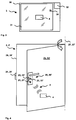
- Fig. 1 is located on the lower floor of the building 1 a building door 2, and in the middle floor of the building 1 and the upper floor of the building 1 two building doors 2, 2 'are arranged.
- the building door 2, 2 ' has at least one door leaf 25, 25' and at least one door frame 26, 26 '.
- the door frame 26, 26 ' has at least one latch plate 24, 24'.
- the locking device 23, 23 ' has at least one latch which can be moved back and forth between at least one motor between a locking position and an open position.
- the bolt In the locked position, the bolt is extended and locks the building door 2, 2 'in the latch plate 24, 24'.
- In the open position, the bolt is moved back and unlocks the building door 2, 2 '.
- By slight force such as pushing or pulling against the unlocked building door 2, 2 'snaps the door leaf 25, 25' from the latch plate 24, 24 'and the building door 2, 2' opens.
- Fig. 3 is the opened building door 2, 2 'about a rotational axis 27, 27' rotatably mounted, the opening of the building door 2, 2 'is represented by a rotated arrow.
- the motor is powered by at least one electrical power supply.
- the electrical power supply is energetically self-sufficient, for example by accumulators, batteries, fuel cells, solar cells, wind turbines, etc ..
- the electrical power is supplied by at least one building voltage network with electric power.
- the building 1 comprises at least one key compartment 3.
- the key compartment 3 is mounted in at least one publicly accessible area of the building 1. According to Fig. 1 the key compartment 3 is located in the entrance area of building 1 on the lower floor.
- the key compartment 3 can also be mounted outside the building envelope and / or in another floor of the building 1.
- the key compartment 3 has at least one main body 30 and at least one shutter 31.
- the main body 30 is made of robust steel, stainless steel, etc., for example.
- the key compartment 3 is stably fixed in the area of the building 1 via the main body 31.
- the main body 31 is embedded in a wall of the building or walled.
- the closure 31 closes at least one interior of the key compartment 3.
- the interior of the key compartment 3 is, for example, a rectangular space of two liters in volume.
- the closure 31 is made of sturdy steel, stainless steel, etc.
- the shutter 31 is made of sensitive glass, plastic, natural material, etc.
- the closure 31 has at least one closing device 33.
- the closing device 33 can be closed with at least one closing plate 34 of the main body 30.
- the closing device 33 may have at least one bolt which can be moved out and back by at least one mechanical key between a closed position and an open position.
- the closing device 33 can also have at least one bolt which can be moved back and forth by at least one motor between a closed position and an open position.
- the shutter 31 is at least one hinge about a rotation axis 37 rotatably mounted on the base body 30.
- the opening of the key compartment 3 is represented by a rotated arrow.
- the engine is powered by at least one electrical power supply supplied with electricity.
- the electric power supply of the motor is energetically self-sufficient, for example, by accumulators, batteries, fuel cells, solar cells, wind turbines, etc. Under energetic autarky is understood in the present invention for at least six months long, advantageously at least twelve months long maintenance-free electrical power supply.
- the closure 31 is at least partially made of glass and the locked key compartment 3 can only be opened by irreversible damage or destruction of the closure 31. For example, a shutter 31 made of glass is smashed or a closure made of plastic or natural material is broken.
- the key 4 opens and / or closes at least one building door 2, 2 '.
- the key 4 may be a master key that can open / close all the building doors 2, 2 'of the building 1.
- the key 4 can also be an area key which can open / close only building doors 2, 2 'of a certain area of the building 1, such area being for example a floor of the building 1 and / or a corridor of the building 1.
- the key 4 can even a single building door 2, 2 'of the building 1 open / close.
- the key 4 is accessible only by opening the normally closed key compartment 3.
- the key 4 is, for example, a passive radio card for radio frequency identification (RFID) with at least one coil, at least one computer-readable data memory and at least one processor.
- the key 4 can also be an active radio card for a radio network such as Bluetooth (IEEE 802.15.1), Zigbee (IEEE 802.15.4), Wi-Fi (IEEE 802.11), etc. with at least one antenna, at least one processor, at least one computer readable data storage and at least one electrical power supply.
- the electrical power supply of the active radio card is energetically self-sufficient, for example by accumulators, batteries, fuel cells, solar cells, etc.
- the computer-readable data memory of the key 4 is at least one computer program means and at least one identification code stored.
- the identification code is a multi-digit sequence of numbers and / or numbers.
- the computer program means is loadable and executable into the key 4 processor.
- the loaded computer program means controls at least one communication between the antenna of the key 4 and a building door 2, 2 '.
- the key 4 is brought into a detection area of at least one transmitting / receiving device 21, 21' of the building door 2, 2 '.
- this communication is represented by curved triple-circle segments.
- the transmitting / receiving device 21, 21 ' is at least one printed circuit board of a few square centimeters in area and a thickness of about one centimeter.
- the transceiver 21, 21 ' is mounted in the door assembly 20, 20'.
- the transceiver 21, 21 ' has at least one antenna, at least one processor, at least one computer-readable data memory and at least one electrical power supply.
- the computer program means is loadable and executable into the processor of the transceiver 21, 21 '.
- the loaded computer program means controls at least one communication between the antenna of the transceiver 21, 21 'and a key 4.
- the antenna of the transceiver 21, 21' generates at least one local radio field 5.
- the detection range of the antenna is Transmit - / Receiving device 21, 21 'is limited to a radius of a few centimeters to a few meters.
- the antenna of the transceiver 21, 21 ' uses a radio frequency of, for example, 125 kHz, 13.56 MHz, 2.45 GHz, etc.
- the passive radio card inductively receives energy from the local radio field 5 via its coil and is energetically activated.
- the energetic activation takes place automatically as soon as the passive radio card is within the detection range of the antenna of the transmitting / receiving device 21, 21 '.
- the computer program means reads the identification code from the computer-readable data memory.
- the coil of the passive radio card sends the read identification code in the local radio field 5 to the transceiver 21, 21 '.
- the energetic activation of the passive radio card and the transmission of the identification code takes place without contact and within a period of less than 2 seconds.
- the antenna of the transceiver 21, 21 ' uses a radio frequency of an Industial Scientific and Medical (ISM) band such as 433 MHz, 902 MHz, 2.40 MHz, etc.
- ISM Industial Scientific and Medical
- the active Radio card In communication with the active Radio card allows the local radio field 5 bidirectional communication according to at least one network protocol, in which each participant over a network address, such as a Media Access Control (MAC) address is uniquely identifiable.
- a connection is established automatically for a communication.
- the processor of the active radio card reads out the identification code stored in the data memory.
- the antenna of the active radio card sends the identification code to the address of the transceiver 21, 21 '.
- the connection establishment of the communication between the active radio card and the transmitting / receiving device 21, 21 'and the transmission of the identification code takes place without contact and in a period of less than 2 seconds.
- the received identification code is transmitted to at least one test device 22, 22 ' .
- the test apparatus 22, 22 ' has at least one processor, at least one computer-readable data memory and at least one electrical power supply.
- the test device 22, 22 ' is at least one printed circuit board of a few square centimeters in area and a thickness of about one centimeter.
- the tester 22, 22 ' is mounted in the door assembly 20, 20'.
- the computer program means is loadable and executable into the processor of the test apparatus 22, 22 '.
- the loaded computer program means controls the recognition of the received identification code.
- the computer program means compares the received identification code with at least one valid access authorization to the building door 2, 2 ', which valid access authorization can also be stored in the computer-readable data memory of the test apparatus 22, 22' and can be loaded into the processor of the test apparatus 22, 22 '. If the received identification code corresponds to a valid access authorization to the building door 2, 2 ', the test apparatus 22, 22' generates at least one positive test signal. The positive test signal is transmitted via at least one signal line to the locking device 23, 23 '. For a transmitted positive test signal, the locking device 23, 23 'controls the motor so that the bolt is moved back from the locking position to the open position.
- the testing device 22, 22 ' may be identical to the transmitting / receiving device 21, 21'. For example, the transceiver 21, 21 ', the test apparatus 22, 22' and the locking device 23, 23 'use one and the same electrical power supply.
- At least one control center 7 has at least one control device 70 with at least one processor, at least one computer-readable data memory, at least one antenna and / or at least one adapter and at least one electrical power supply. At least one computer program means is loaded into the processor from the computer-readable data memory and executed. The computer program means controls the communication of the control device 70 with at least one emergency sensor 6, 6 ', 6 ", 6"' and / or at least one key compartment 3. According to Fig. 1 the central 7 is located on the lower floor of the building 1. The center 7 can also be arranged remotely from the building 1 mobile and / or static. According to Fig.
- the communication between the control device 70 and the emergency sensor 6, 6 ', 6 “, 6” takes place via at least one local radio network 8 such as Bluetooth (IEEE 802.15.1), ZigBee (IEEE 802.15.4), Wi-Fi (IEEE 802.11 ), etc., and / or via at least one fixed network 10 such as Local Operating Network (LON), Ethernet, etc.
- the controller 70 and the emergency sensor 6, 6 ', 6 “, 6”' communicate in the local radio network 8 via the antenna and / or communicate on the fixed network via the adapter.
- the antenna uses a radio frequency of an ISM band such as 433 MHz, 902 MHz, 2.40 MHz, etc.
- the communication in the local radio network 8 is according to Fig.
- the communication in the local radio network 8 and / or in the fixed network 10 is bidirectional according to at least one network protocol, in which each subscriber has a network address, for example a Media Access Control (MAC) address that is uniquely identifiable.
- MAC Media Access Control
- the effective range of the local radio network 8 is only a few tens of meters. If the range of the local radio network 8 is less than the distance between two subscribers, amplified according to Fig. 1 and 5 at least one amplifier 9, the communication between the participants.
- the amplifier 9 has at least one processor, at least one computer-readable data memory, at least one antenna and at least one electrical power supply.
- At least one computer program means is loaded into the processor from the computer-readable data memory and executed.
- the amplifier 9 may be a router, repeater, etc.
- the computer program means controls the communication of the amplifier 9 with at least one emergency sensor 6, 6 ', 6 ", 6"' and / or at least one key compartment 3.
- the emergency sensor 6, 6 ', 6 ", 6"' in the local radio network 8 and / or in the fixed network 10 transmits at least one signal and / or emergency signal to the control device 70 of the center 7.
- the control device 70 analyzes the transmitted signal and / or or emergency signal.
- the controller 70 may analyze an image signal from a camera as to whether at least one emergency signal condition is met, and the controller 70 may also analyze a signal from a switch and / or smoke detector and / or motion detector as to whether at least one emergency signal condition is met.
- the control center 7 transmits at least one activation signal to at least one key compartment 3 of the building 1.
- the emergency sensor 6, 6 ', 6 ", 6"' and / or the control center 7 can report the emergency to at least one emergency service.
- the notification of the emergency includes an indication of the location and / or time of emergency correlated with the emergency signal in the building 1.
- the emergency service is for example the police, fire, ambulance, etc ..
- the notification of the emergency can Also include the transmission of the emergency in the building 1 defining emergency signal to the emergency service.
- the key compartment 3 has at least one communication device 32 .
- the communication device 32 is at least one printed circuit board of a few square centimeters in area and a thickness of about one centimeter.
- the communication device 32 is mounted in the interior of the key compartment 3.
- the communication device 32 has at least one antenna, at least one processor, at least one computer-readable data memory and at least one electrical power supply.
- the computer program means is loadable and executable into the processor of the communication device 32.
- the loaded computer program means controls at least one communication in the local radio network 8 between the antenna of the communication device 32 and the antenna of the control device 70 of the center 7.
- the activation signal is received by the antenna of the communication device 32.
- the received activation signal is transmitted to the shooting device 33 via at least one signal line.
- the closing device 33 controls the motor so that the bolt is moved back from the closed position to the open position.
- the key compartment 3 can now be opened.
- the emergency service notified in the building 1 via the emergency reaches the building 1 and can remove the key 4 from the key compartment 3 by removing the shutter 31.
- the communication device 32 may be identical to the closing device 33.
- the communication device 32 and the locking device 33 use one and the same electrical power supply.
- the key compartment 3 has at least one sabotage sensor 35 .
- the sabotage sensor 35 detects at least one removal of the shutter 31.
- the sabotage sensor 35 is, for example, an electrical and / or mechanical contactor.
- the sabotage sensor 35 generates at least one sabotage signal.
- the sabotage signal is transmitted to the communication device via at least one signal line 32 transmitted.
- the antenna of the communication device 32 communicates the sabotage signal in the local radio network 8 to the antenna of the center 7.
- the sabotage signal is received by the antenna of the center 7.
- the controller 70 compares whether there is an emergency for the received sabotage signal of the key compartment 3. If there is an emergency, no emergency service will be alerted.
- At least one emergency service will be alerted.
- An emergency occurs when the control device 70 has previously sent an activation signal to that key compartment 3 from which the sabotage signal also originated.
- the emergency service is, for example, the police, fire brigade, ambulance, etc.
- the alerting of the emergency service includes an indication of the location and / or time of sabotage correlated with the sabotage signal on the key compartment 3.
Landscapes
- Engineering & Computer Science (AREA)
- Computer Networks & Wireless Communication (AREA)
- Physics & Mathematics (AREA)
- General Physics & Mathematics (AREA)
- Lock And Its Accessories (AREA)
- Alarm Systems (AREA)
Claims (10)
- Système d'accès à un bâtiment (1) ; étant précisé que plusieurs casiers pour clé (3) sont accessibles publiquement dans au moins une zone du bâtiment (1) ; que parmi les casiers pour clé (3), un casier pour clé (3) comporte au moins une clé (4) pour au moins une porte (2, 2') du bâtiment (1) ; et on a accès à la clé (4) en enlevant au moins un couvercle (31) du casier pour clé (3), étant précisé que le système d'accès comporte ce qui suit :la ou les portes de bâtiment (2, 2'), qui comportent au moins un émetteur/récepteur (21, 21'), lequel émetteur/récepteur (21, 21') est installé pour recevoir un code d'identification de la clé (4) mémorisé dans ladite clé (4), quand la clé (4) arrive dans au moins une zone de détection de l'émetteur/récepteur (21, 21') ;au moins un dispositif de contrôle (22, 22') qui est installé pour vérifier s'il existe pour le code d'identification reçu au moins une autorisation d'accès valable à la porte de bâtiment (2, 2') ;au moins un dispositif de verrouillage (23, 23') dans une garniture de porte, qui est installé pour déverrouiller la porte de bâtiment (2, 2') au cas où il existe pour le code d'identification reçu une autorisation d'accès valable à la porte de bâtiment (2, 2') ; etau moins un détecteur de situation d'urgence (6, 6', 6", 6"') dans au moins une zone du bâtiment (1), lequel détecteur de situation d'urgence est installé pour détecter au moins un signal et pour communiquer au moins un signal et/ou un signal d'urgence à au moins un central (7), étant précisé que le central (7), pour un signal d'urgence communiqué, communique un signal d'activation au casier pour clé (3) ; caractérisé parun détecteur de sabotage (35) que comporte le casier pour clé (3), lequel détecteur de sabotage (35) est installé pour détecter l'enlèvement du couvercle (31) et, pour un enlèvement détecté du couvercle (31), pour produire au moins un signal de sabotage, et est installé pour transmettre le signal de sabotage, par l'intermédiaire d'au moins une ligne de signaux, à un dispositif de communication (32) du casier pour clé (3), lequel dispositif de communication (32) est installé pour communiquer le signal de sabotage, par un réseau radio local (8), au central (7), lequel central (7) est installé pour recevoir le signal de sabotage grâce à une antenne du central (7), étant précisé qu'au moins un dispositif de commande (70) du central (7) est installé pour voir par comparaison s'il existe une situation d'urgence pour le signal de sabotage du casier pour clé (3) reçu, qu'il existe une situation d'urgence si le dispositif de commande (70) a précédemment envoyé au casier pour clé (3) un signal d'activation pour lequel un dispositif de fermeture (33) dudit casier (3) a ouvert le couvercle (31), qu'au cas où il existe une situation d'urgence, aucun service d'urgence n'est alerté, qu'au cas où il n'existe pas de situation d'urgence, le dispositif de commande (70) est installé pour alerter, pour un signal de sabotage reçu, au moins un service d'urgence, et qu'au moins une alerte du service d'urgence contient au moins une indication sur le lieu et/ou l'heure d'un sabotage, au niveau du casier pour clé (3), corrélé avec le signal de sabotage.
- Système d'accès selon la revendication 1, caractérisé en ce qu'au moins une antenne de l'émetteur/récepteur (21,21') produit au moins un champ hertzien local (5)
et/ou en ce qu'au moins une antenne de l'émetteur/récepteur (21, 21') produit au moins un champ hertzien local (5) ; et en ce que la couverture de l'antenne de l'émetteur/récepteur (21, 21') est limitée à un rayon de quelques centimètres à quelques mètres
et/ou en ce qu'au moins une antenne de l'émetteur/récepteur (21, 21') produit au moins un champ hertzien local (5) ; et en ce que la clé (4) est une carte radio passive pour une identification par radiofréquence
et/ou en ce qu'au moins une antenne de l'émetteur/récepteur (21, 21') produit au moins un champ hertzien local (5) ; en ce que la clé (4) est une carte radio passive avec au moins une bobine et au moins une mémoire de données lisible par ordinateur ; en ce que le code d'identification est stocké dans la mémoire de données lisible par ordinateur ; en ce que dès que la carte radio passive se trouve dans le champ hertzien local (5), la bobine reçoit de manière inductive l'énergie dans le champ hertzien local (5) et active énergétiquement la carte radio passive ; en ce que la carte radio passive activée énergétiquement extrait le code d'identification de la mémoire de données lisible par ordinateur ; et en ce que la bobine de la carte radio passive activée énergétiquement envoie le code d'identification extrait, dans le champ hertzien local (5), à l'antenne de l'émetteur/récepteur (21, 21')
et/ou en ce qu'au moins une antenne de l'émetteur/récepteur (21, 21') produit au moins un champ hertzien local (5) ; et en ce que la clé (4) est une carte radio active pour un réseau radio tel que Bluetooth et/ou ZigBee et/ou Wi-Fi
et/ou en ce qu'au moins une antenne de l'émetteur/récepteur (21, 21') produit au moins un champ hertzien local (5) ; en ce que la clé (4) est une carte radio active avec au moins une antenne et au moins une mémoire de données lisible par ordinateur et au moins une alimentation électrique ; en ce que le code d'identification est stocké dans la mémoire de données lisible par ordinateur ; et en ce que dès que la carte radio active se trouve dans le champ hertzien local (5), la carte radio active extrait le code d'identification de la mémoire de données lisible par ordinateur et l'antenne de la carte radio active envoie ledit code d'identification extrait, dans le champ hertzien (5), à l'antenne de l'émetteur/récepteur (21, 21'). - Système d'accès selon l'une des revendications 1 ou 2, caractérisé en ce que le détecteur de situation d'urgence (6, 6', 6", 6"') est une caméra
et/ou en ce que le détecteur de situation d'urgence (6, 6', 6", 6"') est un commutateur et/ou en ce que le détecteur de situation d'urgence (6, 6', 6", 6"') est un détecteur de fumée
et/ou en ce que le détecteur de situation d'urgence (6, 6', 6", 6"') est un détecteur de présence
et/ou en ce que le signal remplit au moins une condition pour un signal d'urgence si une personne reste assez longtemps dans une zone du bâtiment (1)
et/ou en ce que le signal remplit au moins une condition pour un signal d'urgence si une personne est allongé assez longtemps sur un sol du bâtiment (1)
et/ou en ce que le signal remplit au moins une condition pour un signal d'urgence si une personne est allongée assez longtemps sur un sol du bâtiment (1) et ne bouge pas
et/ou en ce que le signal remplit au moins une condition pour un signal d'urgence si une personne est allongée assez longtemps sur un sol du bâtiment (1) et agite au moins une main
et/ou en ce que le signal remplit au moins une condition pour un signal d'urgence si une personne se déplace dans le bâtiment (1) à une vitesse définie
et/ou en ce que le détecteur de situation d'urgence (6, 6', 6", 6"') est un commutateur ; en ce que le signal remplit au moins une condition pour un signal d'urgence si le commutateur détecte le signal pour une durée définie, librement réglable ;
et/ou en ce que le détecteur de situation d'urgence (6, 6', 6", 6"') est un commutateur ; en ce que le signal remplit au moins une condition pour un signal d'urgence si le commutateur détecte comme signal une pression définie, librement réglable, d'au moins 2,5 Newton, de préférence d'au moins cinq Newton, de préférence d'au moins dix Newton
et/ou en ce que le détecteur de situation d'urgence (6, 6', 6", 6"') est un détecteur de fumée ; en ce que le signal remplit au moins une condition pour un signal d'urgence si un signal détecté dépasse au moins une valeur seuil librement réglable
et/ou en ce que le détecteur de situation d'urgence (6, 6', 6", 6"') est un détecteur de présence ; en ce que le signal remplit au moins une condition pour un signal d'urgence si le détecteur de présence détecte comme signal un déplacement dans un laps de temps défini, dans au moins une zone du bâtiment (1)
et/ou en ce que le détecteur de situation d'urgence (6, 6', 6", 6"') est un détecteur de présence ; en ce que le signal remplit au moins une condition pour un signal d'urgence si le détecteur de présence détecte comme signal un déplacement dans au moins une zone du bâtiment (1) dans un laps de temps assez long
et/ou en ce que le détecteur de situation d'urgence (6, 6', 6", 6"') est un détecteur de présence ; en ce que le signal remplit au moins une condition pour un signal d'urgence si le détecteur de présence détecte comme signal un déplacement dans le bâtiment (1) à une vitesse définie. - Système d'accès selon la revendication 3, caractérisé en ce que le détecteur de situation d'urgence (6, 6', 6", 6"') comporte au moins une antenne ; et en ce que l'antenne du détecteur de situation d'urgence (6, 6', 6", 6"') dans le réseau radio local (8) transmet au moins un signal et/ou un signal d'urgence à l'antenne du dispositif de commande (70)
et/ou en ce qu'au moins un adaptateur du détecteur de situation d'urgence (6, 6', 6", 6'") communique par l'intermédiaire d'au moins un réseau fixe (10) avec au moins un adaptateur d'au moins un dispositif de commande (70) du ou des centraux (7) ; et en ce que l'adaptateur du détecteur de situation d'urgence (6, 6', 6", 6"') dans le réseau fixe (10) transmet au moins un signal et/ou un signal d'urgence à l'adaptateur du dispositif de commande (70)
et/ou en ce que le détecteur de situation d'urgence (6, 6', 6", 6"') procède à une analyse pour voir si au moins une condition pour un signal d'urgence est remplie
et/ou en ce que le détecteur de situation d'urgence (6, 6', 6", 6"') communique au moins un signal et/ou un signal d'urgence au central ou aux centraux (7) ; et en ce qu'au moins un dispositif de commande (70) du central procède à une analyse pour voir si au moins une condition pour un signal d'urgence est remplie
et/ou en ce que le détecteur de situation d'urgence (6, 6', 6", 6"') procède à une analyse pour voir si au moins une condition pour un signal d'urgence est remplie ; en ce que dans le cas où une condition pour un signal d'urgence est remplie, le détecteur de situation d'urgence (6, 6', 6", 6"') pour un signal d'urgence alerte au moins un service d'urgence ; et en ce qu'au moins une alerte d'un service d'urgence contient au moins une indication sur le lieu et/ou l'heure d'une situation d'urgence dans le bâtiment (1), corrélée avec le signal d'urgence
et/ou en ce que le détecteur de situation d'urgence (6, 6', 6", 6"') procède à une analyse pour voir si au moins une condition pour un signal d'urgence est remplie ; en ce que dans le cas où une condition pour un signal d'urgence est remplie, le détecteur de situation d'urgence (6, 6', 6", 6"') pour un signal d'urgence alerte au moins un service d'urgence ; et en ce qu'au moins une alerte d'un service d'urgence contient au moins une transmission d'au moins un signal d'urgence corrélé avec la situation d'urgence dans le bâtiment (1)
et/ou en ce que le détecteur de situation d'urgence (6, 6', 6", 6"') dans le réseau radio local (8) communique avec le ou les centraux (7) ; en ce qu'au moins un amplificateur (9) comporte au moins une antenne ; et en ce que l'antenne de l'amplificateur (9) amplifie la communication dans le réseau radio local (8). - Système d'accès selon la revendication 4, caractérisé en ce que le dispositif de communication (32) du casier pour clé (3) comporte au moins une antenne ; et en ce que l'antenne du dispositif de commande (70) pour un signal d'urgence dans le réseau radio local (8) transmet le signal d'activation à l'antenne du dispositif de communication (32) du casier pour clé (3)
et/ou en ce qu'au moins un amplificateur (9) comporte au moins une antenne ; et en ce que l'antenne de l'amplificateur (9) amplifie la communication dans le réseau radio local (8). - Casier pour clé (3) à utiliser dans un système d'accès selon l'une des revendications 1 à 5, caractérisé en ce que le casier pour clé (3) comporte au moins un corps de base (30).
- Casier pour clé (3) selon la revendication 6, caractérisé en ce que le couvercle (31) est fabriqué au moins par zones en verre ; et en ce que le couvercle (31) ne peut être enlevé qu'en étant dégradé ou détruit de manière irréversible
et/ou en ce que le dispositif de communication (32) est au moins une carte imprimée
et/ou en ce qu'au moins une alimentation électrique est disposée dans le casier pour clé (3) ; et en ce que l'alimentation électrique est électriquement autonome
et/ou en ce qu'au moins une alimentation électrique est disposée dans le casier pour clé (3) ; et en ce que l'alimentation électrique alimente le dispositif de fermeture (33) en courant électrique. - Procédé pour faire fonctionner un système d'accès à un bâtiment (1) selon l'une des revendications 1 à 5, caractérisé
en ce qu'au moins un détecteur de situation d'urgence (6, 6', 6", 6"') détecte au moins une zone du bâtiment (1) sous la forme d'au moins un signal ;
en ce qu'une analyse est réalisée pour voir si le signal détecté remplit au moins une condition pour un signal d'urgence, grâce au fait qu'une antenne du détecteur de situation d'urgence (6, 6', 6", 6"') dans au moins un réseau radio local (8) transmet au moins un signal à au moins une antenne d'un dispositif de commande (70) d'un central ;
en ce que dans le cas où la condition pour un signal d'urgence est remplie, au moins une clé (4) contenue dans au moins un casier pour clé (3) du bâtiment (1) est rendue accessible grâce au fait que le central (7) communique au moins un signal d'activation au casier pour clé (3) ;
en ce qu'au moins un dispositif de fermeture (33) du casier pour clé (3), pour un signal d'activation communiqué, ouvre le couvercle (31) ;
en ce qu'au moins un code d'identification est communiqué par la clé (4) à au moins une porte de bâtiment (2, 2') ;
en ce qu'un contrôle est effectué pour voir s'il existe pour le code d'identification communiqué une autorisation d'accès valable à la porte de bâtiment (2, 2') ;
en ce que dans le cas où il existe une autorisation d'accès valable à la porte de bâtiment (2, 2'), ladite porte de bâtiment (2, 2') est déverrouillée ;
en ce qu'un détecteur de sabotage (35) d'un casier pour clé (3) détecte au moins un enlèvement d'un couvercle (31) d'un casier pour clé (3) ;
en ce que le détecteur de sabotage (35) produit, pour un enlèvement détecté du couvercle (31), au moins un signal de sabotage ;
en ce que le détecteur de sabotage (35) transmet le signal de sabotage par l'intermédiaire d'une ligne de signaux à un dispositif de communication (32) ;
en ce que le dispositif de communication (32) communique le signal de sabotage au central (7) ;
en ce que le central (7) reçoit le signal de sabotage ;
en ce qu'au moins un dispositif de commande (70) du central (7) procède à une comparaison pour voir s'il existe une situation d'urgence pour le signal de sabotage du casier pour clé (3) reçu, étant précisé qu'il existe une situation d'urgence si le dispositif de commande (70) a précédemment envoyé le signal d'activation au casier pour clé (3) ;
en ce que dans le cas où il n'existe pas de signal d'urgence, le dispositif de commande (70), pour le signal de sabotage reçu, alerte au moins un service d'urgence ; et
en ce qu'au moins une alerte du service d'urgence contient au moins une indication sur le lieu et/ou l'heure d'un sabotage, au niveau du casier pour clé (3), corrélé avec le signal de sabotage. - Produit de programme informatique comprenant un support de programme informatique apte à réaliser le procédé pour faire fonctionner un système d'accès selon la revendication 8 grâce au fait qu'au moins une étape de procédé est réalisée si le support de programme informatique est chargé dans au moins un processeur d'au moins un émetteur/récepteur (21, 21') et/ou d'au moins un dispositif de contrôle (22, 22') et/ou d'au moins un dispositif de commande (70) et/ou d'au moins un dispositif de communication (32).
- Mémoire de données lisible par ordinateur, comprenant un produit de programme informatique selon la revendication 9.
Priority Applications (3)
| Application Number | Priority Date | Filing Date | Title |
|---|---|---|---|
| EP08169369.9A EP2189598B1 (fr) | 2008-11-18 | 2008-11-18 | Système d'accès à un bâtiment |
| ES08169369.9T ES2587062T3 (es) | 2008-11-18 | 2008-11-18 | Sistema de acceso a un edificio |
| PL08169369T PL2189598T3 (pl) | 2008-11-18 | 2008-11-18 | System dostępu do budynku |
Applications Claiming Priority (1)
| Application Number | Priority Date | Filing Date | Title |
|---|---|---|---|
| EP08169369.9A EP2189598B1 (fr) | 2008-11-18 | 2008-11-18 | Système d'accès à un bâtiment |
Publications (2)
| Publication Number | Publication Date |
|---|---|
| EP2189598A1 EP2189598A1 (fr) | 2010-05-26 |
| EP2189598B1 true EP2189598B1 (fr) | 2016-05-11 |
Family
ID=40430577
Family Applications (1)
| Application Number | Title | Priority Date | Filing Date |
|---|---|---|---|
| EP08169369.9A Active EP2189598B1 (fr) | 2008-11-18 | 2008-11-18 | Système d'accès à un bâtiment |
Country Status (3)
| Country | Link |
|---|---|
| EP (1) | EP2189598B1 (fr) |
| ES (1) | ES2587062T3 (fr) |
| PL (1) | PL2189598T3 (fr) |
Families Citing this family (6)
| Publication number | Priority date | Publication date | Assignee | Title |
|---|---|---|---|---|
| DE102012104955B4 (de) | 2012-06-08 | 2022-02-17 | Kiwi.Ki Gmbh | Verfahren zum kryptographisch gesicherten Beweis der Anwesenheit eines Identity-Tokens im Bereich eines Identity-Sensors, sowie System für ein solches Verfahren |
| PL2928803T3 (pl) | 2012-12-06 | 2017-04-28 | Inventio Ag | Wprowadzanie poleceń zamka z wykorzystaniem gestów |
| DE102014105244A1 (de) * | 2013-12-05 | 2015-06-11 | Deutsche Post Ag | Verfahren zum Deaktivieren des Verriegelns zumindest einer Tür eines Gehäuses |
| DE102017204744B4 (de) * | 2017-03-21 | 2019-11-14 | Leoni Kabel Gmbh | Vorrichtung zur Überwachung eines Gebäudes |
| CN112258711A (zh) * | 2020-07-28 | 2021-01-22 | 上海有间建筑科技有限公司 | 一种基于物联网的智慧校园用校园监护系统 |
| CN111986355A (zh) * | 2020-08-31 | 2020-11-24 | 广东电网有限责任公司广州供电局 | 配电房门禁验证系统 |
Family Cites Families (6)
| Publication number | Priority date | Publication date | Assignee | Title |
|---|---|---|---|---|
| DE3204763A1 (de) * | 1982-02-11 | 1983-08-18 | Colt International Holdings AG, 6300 Zug | Verschlussbehaelter |
| DE19913931B4 (de) * | 1999-03-26 | 2010-12-30 | Scheuermann, Carl H. | Überprüfungsverfahren und elektromechanisches Schließsystem |
| EP1088958A3 (fr) | 1999-09-28 | 2003-01-22 | Siemens Aktiengesellschaft | Coffre à clé et système permettant l'accès à un bâtiment pour un fournisseur de services |
| DE102004041518A1 (de) | 2004-03-12 | 2005-09-29 | Dom-Sicherheitstechnik Gmbh & Co. Kg | Schließzylinder und Schließverfahren |
| DE202005021303U1 (de) * | 2004-11-23 | 2007-09-13 | Ident Technology Ag | Schließanordnung |
| DE102005032379A1 (de) * | 2005-07-08 | 2007-01-11 | Conti Temic Microelectronic Gmbh | Zugangskontrollsystem für ein Kraftfahrzeug |
-
2008
- 2008-11-18 EP EP08169369.9A patent/EP2189598B1/fr active Active
- 2008-11-18 PL PL08169369T patent/PL2189598T3/pl unknown
- 2008-11-18 ES ES08169369.9T patent/ES2587062T3/es active Active
Also Published As
| Publication number | Publication date |
|---|---|
| ES2587062T3 (es) | 2016-10-20 |
| EP2189598A1 (fr) | 2010-05-26 |
| PL2189598T3 (pl) | 2017-07-31 |
Similar Documents
| Publication | Publication Date | Title |
|---|---|---|
| EP2189598B1 (fr) | Système d'accès à un bâtiment | |
| US11645904B2 (en) | Drone-augmented emergency response services | |
| CA2930807C (fr) | Systeme de securite servant a reperer les perturbations dans un batiment | |
| US20090122143A1 (en) | Security system and network | |
| US11514764B2 (en) | Smartlock system for improved fire safety | |
| CN201826554U (zh) | 一种银行atm机防卫舱 | |
| Burchett | Advances in through wall radar for search, rescue and security applications | |
| RU2623420C1 (ru) | Интеллектуальный досмотровый барьер | |
| CN105139487A (zh) | 一种安全防护远程管理方法 | |
| EP3445927B1 (fr) | Système pour permettre l'évacuation de bâtiments en cas de tremblement de terre, et son procédé de fonctionnement | |
| US11210883B2 (en) | Facility access regulating system and method | |
| US11021893B2 (en) | Security system for a building | |
| CN205563895U (zh) | 一种学生宿舍防盗管理装置 | |
| CN109840979A (zh) | 一种物联网小区智慧门禁系统 | |
| JP3690361B2 (ja) | 部外者監視システム | |
| CN207424967U (zh) | 智能出入感应系统及智能门锁 | |
| US20220074233A1 (en) | Security system for a building | |
| CN204360190U (zh) | 放射源仓库监控系统 | |
| RU82496U1 (ru) | Комплекс инженерно-технической защиты охраняемого объекта | |
| DE102005020885A1 (de) | Zentrales radarbasiertes Alarmsystem zur Überwachung von Gebäuden und Räumen ohne externe Sensorik | |
| KR20120026251A (ko) | 출입 관리 장치 | |
| RU2303818C1 (ru) | Способ и система обеспечения безопасности объекта | |
| DE202019005093U1 (de) | Sensormeldeanlage zur Sicherung von Tresoren bei unerlaubten Zugriff mit simultaner Informationsübermittlung | |
| KR102462824B1 (ko) | 수용거실별 전자잠금장치를 이용한 위급상황예측 운영시스템 | |
| AU2021105181A4 (en) | Intelligent system & method for home surveillance with warning of robber activities using iot & artificial intelligence approach |
Legal Events
| Date | Code | Title | Description |
|---|---|---|---|
| PUAI | Public reference made under article 153(3) epc to a published international application that has entered the european phase |
Free format text: ORIGINAL CODE: 0009012 |
|
| AK | Designated contracting states |
Kind code of ref document: A1 Designated state(s): AT BE BG CH CY CZ DE DK EE ES FI FR GB GR HR HU IE IS IT LI LT LU LV MC MT NL NO PL PT RO SE SI SK TR |
|
| AX | Request for extension of the european patent |
Extension state: AL BA MK RS |
|
| 17P | Request for examination filed |
Effective date: 20100920 |
|
| 17Q | First examination report despatched |
Effective date: 20101011 |
|
| AKX | Designation fees paid |
Designated state(s): AT BE BG CH CY CZ DE DK EE ES FI FR GB GR HR HU IE IS IT LI LT LU LV MC MT NL NO PL PT RO SE SI SK TR |
|
| GRAP | Despatch of communication of intention to grant a patent |
Free format text: ORIGINAL CODE: EPIDOSNIGR1 |
|
| INTG | Intention to grant announced |
Effective date: 20151211 |
|
| RIN1 | Information on inventor provided before grant (corrected) |
Inventor name: FRIEDLI, PAUL Inventor name: SCHWARZENTRUBER, JOSEF |
|
| GRAS | Grant fee paid |
Free format text: ORIGINAL CODE: EPIDOSNIGR3 |
|
| GRAA | (expected) grant |
Free format text: ORIGINAL CODE: 0009210 |
|
| AK | Designated contracting states |
Kind code of ref document: B1 Designated state(s): AT BE BG CH CY CZ DE DK EE ES FI FR GB GR HR HU IE IS IT LI LT LU LV MC MT NL NO PL PT RO SE SI SK TR |
|
| REG | Reference to a national code |
Ref country code: GB Ref legal event code: FG4D Free format text: NOT ENGLISH |
|
| REG | Reference to a national code |
Ref country code: CH Ref legal event code: EP |
|
| REG | Reference to a national code |
Ref country code: AT Ref legal event code: REF Ref document number: 798820 Country of ref document: AT Kind code of ref document: T Effective date: 20160515 |
|
| REG | Reference to a national code |
Ref country code: IE Ref legal event code: FG4D Free format text: LANGUAGE OF EP DOCUMENT: GERMAN |
|
| REG | Reference to a national code |
Ref country code: DE Ref legal event code: R096 Ref document number: 502008014193 Country of ref document: DE |
|
| REG | Reference to a national code |
Ref country code: NL Ref legal event code: FP |
|
| REG | Reference to a national code |
Ref country code: LT Ref legal event code: MG4D |
|
| REG | Reference to a national code |
Ref country code: ES Ref legal event code: FG2A Ref document number: 2587062 Country of ref document: ES Kind code of ref document: T3 Effective date: 20161020 |
|
| PG25 | Lapsed in a contracting state [announced via postgrant information from national office to epo] |
Ref country code: NO Free format text: LAPSE BECAUSE OF FAILURE TO SUBMIT A TRANSLATION OF THE DESCRIPTION OR TO PAY THE FEE WITHIN THE PRESCRIBED TIME-LIMIT Effective date: 20160811 Ref country code: LT Free format text: LAPSE BECAUSE OF FAILURE TO SUBMIT A TRANSLATION OF THE DESCRIPTION OR TO PAY THE FEE WITHIN THE PRESCRIBED TIME-LIMIT Effective date: 20160511 |
|
| REG | Reference to a national code |
Ref country code: FR Ref legal event code: PLFP Year of fee payment: 9 |
|
| PG25 | Lapsed in a contracting state [announced via postgrant information from national office to epo] |
Ref country code: PT Free format text: LAPSE BECAUSE OF FAILURE TO SUBMIT A TRANSLATION OF THE DESCRIPTION OR TO PAY THE FEE WITHIN THE PRESCRIBED TIME-LIMIT Effective date: 20160912 Ref country code: LV Free format text: LAPSE BECAUSE OF FAILURE TO SUBMIT A TRANSLATION OF THE DESCRIPTION OR TO PAY THE FEE WITHIN THE PRESCRIBED TIME-LIMIT Effective date: 20160511 Ref country code: SE Free format text: LAPSE BECAUSE OF FAILURE TO SUBMIT A TRANSLATION OF THE DESCRIPTION OR TO PAY THE FEE WITHIN THE PRESCRIBED TIME-LIMIT Effective date: 20160511 Ref country code: GR Free format text: LAPSE BECAUSE OF FAILURE TO SUBMIT A TRANSLATION OF THE DESCRIPTION OR TO PAY THE FEE WITHIN THE PRESCRIBED TIME-LIMIT Effective date: 20160812 Ref country code: HR Free format text: LAPSE BECAUSE OF FAILURE TO SUBMIT A TRANSLATION OF THE DESCRIPTION OR TO PAY THE FEE WITHIN THE PRESCRIBED TIME-LIMIT Effective date: 20160511 |
|
| PG25 | Lapsed in a contracting state [announced via postgrant information from national office to epo] |
Ref country code: IT Free format text: LAPSE BECAUSE OF FAILURE TO SUBMIT A TRANSLATION OF THE DESCRIPTION OR TO PAY THE FEE WITHIN THE PRESCRIBED TIME-LIMIT Effective date: 20160511 |
|
| PG25 | Lapsed in a contracting state [announced via postgrant information from national office to epo] |
Ref country code: DK Free format text: LAPSE BECAUSE OF FAILURE TO SUBMIT A TRANSLATION OF THE DESCRIPTION OR TO PAY THE FEE WITHIN THE PRESCRIBED TIME-LIMIT Effective date: 20160511 Ref country code: CZ Free format text: LAPSE BECAUSE OF FAILURE TO SUBMIT A TRANSLATION OF THE DESCRIPTION OR TO PAY THE FEE WITHIN THE PRESCRIBED TIME-LIMIT Effective date: 20160511 Ref country code: RO Free format text: LAPSE BECAUSE OF FAILURE TO SUBMIT A TRANSLATION OF THE DESCRIPTION OR TO PAY THE FEE WITHIN THE PRESCRIBED TIME-LIMIT Effective date: 20160511 Ref country code: SK Free format text: LAPSE BECAUSE OF FAILURE TO SUBMIT A TRANSLATION OF THE DESCRIPTION OR TO PAY THE FEE WITHIN THE PRESCRIBED TIME-LIMIT Effective date: 20160511 Ref country code: EE Free format text: LAPSE BECAUSE OF FAILURE TO SUBMIT A TRANSLATION OF THE DESCRIPTION OR TO PAY THE FEE WITHIN THE PRESCRIBED TIME-LIMIT Effective date: 20160511 |
|
| REG | Reference to a national code |
Ref country code: DE Ref legal event code: R097 Ref document number: 502008014193 Country of ref document: DE |
|
| PLBE | No opposition filed within time limit |
Free format text: ORIGINAL CODE: 0009261 |
|
| STAA | Information on the status of an ep patent application or granted ep patent |
Free format text: STATUS: NO OPPOSITION FILED WITHIN TIME LIMIT |
|
| 26N | No opposition filed |
Effective date: 20170214 |
|
| PG25 | Lapsed in a contracting state [announced via postgrant information from national office to epo] |
Ref country code: SI Free format text: LAPSE BECAUSE OF FAILURE TO SUBMIT A TRANSLATION OF THE DESCRIPTION OR TO PAY THE FEE WITHIN THE PRESCRIBED TIME-LIMIT Effective date: 20160511 |
|
| REG | Reference to a national code |
Ref country code: IE Ref legal event code: MM4A |
|
| PG25 | Lapsed in a contracting state [announced via postgrant information from national office to epo] |
Ref country code: LU Free format text: LAPSE BECAUSE OF NON-PAYMENT OF DUE FEES Effective date: 20161130 |
|
| REG | Reference to a national code |
Ref country code: FR Ref legal event code: PLFP Year of fee payment: 10 |
|
| PG25 | Lapsed in a contracting state [announced via postgrant information from national office to epo] |
Ref country code: IE Free format text: LAPSE BECAUSE OF NON-PAYMENT OF DUE FEES Effective date: 20161118 |
|
| REG | Reference to a national code |
Ref country code: AT Ref legal event code: MM01 Ref document number: 798820 Country of ref document: AT Kind code of ref document: T Effective date: 20161118 |
|
| PG25 | Lapsed in a contracting state [announced via postgrant information from national office to epo] |
Ref country code: AT Free format text: LAPSE BECAUSE OF NON-PAYMENT OF DUE FEES Effective date: 20161118 |
|
| PG25 | Lapsed in a contracting state [announced via postgrant information from national office to epo] |
Ref country code: HU Free format text: LAPSE BECAUSE OF FAILURE TO SUBMIT A TRANSLATION OF THE DESCRIPTION OR TO PAY THE FEE WITHIN THE PRESCRIBED TIME-LIMIT; INVALID AB INITIO Effective date: 20081118 Ref country code: CY Free format text: LAPSE BECAUSE OF FAILURE TO SUBMIT A TRANSLATION OF THE DESCRIPTION OR TO PAY THE FEE WITHIN THE PRESCRIBED TIME-LIMIT Effective date: 20160511 |
|
| PG25 | Lapsed in a contracting state [announced via postgrant information from national office to epo] |
Ref country code: IS Free format text: LAPSE BECAUSE OF FAILURE TO SUBMIT A TRANSLATION OF THE DESCRIPTION OR TO PAY THE FEE WITHIN THE PRESCRIBED TIME-LIMIT Effective date: 20160511 Ref country code: MC Free format text: LAPSE BECAUSE OF FAILURE TO SUBMIT A TRANSLATION OF THE DESCRIPTION OR TO PAY THE FEE WITHIN THE PRESCRIBED TIME-LIMIT Effective date: 20160511 |
|
| PG25 | Lapsed in a contracting state [announced via postgrant information from national office to epo] |
Ref country code: BG Free format text: LAPSE BECAUSE OF FAILURE TO SUBMIT A TRANSLATION OF THE DESCRIPTION OR TO PAY THE FEE WITHIN THE PRESCRIBED TIME-LIMIT Effective date: 20160511 |
|
| PG25 | Lapsed in a contracting state [announced via postgrant information from national office to epo] |
Ref country code: MT Free format text: LAPSE BECAUSE OF FAILURE TO SUBMIT A TRANSLATION OF THE DESCRIPTION OR TO PAY THE FEE WITHIN THE PRESCRIBED TIME-LIMIT Effective date: 20160511 |
|
| PGFP | Annual fee paid to national office [announced via postgrant information from national office to epo] |
Ref country code: FI Payment date: 20191121 Year of fee payment: 12 Ref country code: NL Payment date: 20191120 Year of fee payment: 12 |
|
| PGFP | Annual fee paid to national office [announced via postgrant information from national office to epo] |
Ref country code: PL Payment date: 20191106 Year of fee payment: 12 |
|
| REG | Reference to a national code |
Ref country code: FI Ref legal event code: MAE |
|
| REG | Reference to a national code |
Ref country code: NL Ref legal event code: MM Effective date: 20201201 |
|
| PG25 | Lapsed in a contracting state [announced via postgrant information from national office to epo] |
Ref country code: FI Free format text: LAPSE BECAUSE OF NON-PAYMENT OF DUE FEES Effective date: 20201118 |
|
| PG25 | Lapsed in a contracting state [announced via postgrant information from national office to epo] |
Ref country code: NL Free format text: LAPSE BECAUSE OF NON-PAYMENT OF DUE FEES Effective date: 20201201 |
|
| PG25 | Lapsed in a contracting state [announced via postgrant information from national office to epo] |
Ref country code: PL Free format text: LAPSE BECAUSE OF NON-PAYMENT OF DUE FEES Effective date: 20201118 |
|
| REG | Reference to a national code |
Ref country code: DE Ref legal event code: R084 Ref document number: 502008014193 Country of ref document: DE |
|
| PGFP | Annual fee paid to national office [announced via postgrant information from national office to epo] |
Ref country code: GB Payment date: 20231121 Year of fee payment: 16 |
|
| PGFP | Annual fee paid to national office [announced via postgrant information from national office to epo] |
Ref country code: ES Payment date: 20231218 Year of fee payment: 16 |
|
| PGFP | Annual fee paid to national office [announced via postgrant information from national office to epo] |
Ref country code: TR Payment date: 20231107 Year of fee payment: 16 Ref country code: FR Payment date: 20231123 Year of fee payment: 16 Ref country code: DE Payment date: 20231127 Year of fee payment: 16 Ref country code: CH Payment date: 20231201 Year of fee payment: 16 |
|
| PGFP | Annual fee paid to national office [announced via postgrant information from national office to epo] |
Ref country code: BE Payment date: 20231124 Year of fee payment: 16 |