EP2189301A1 - Non-pneumatic tire - Google Patents
Non-pneumatic tire Download PDFInfo
- Publication number
- EP2189301A1 EP2189301A1 EP08829703A EP08829703A EP2189301A1 EP 2189301 A1 EP2189301 A1 EP 2189301A1 EP 08829703 A EP08829703 A EP 08829703A EP 08829703 A EP08829703 A EP 08829703A EP 2189301 A1 EP2189301 A1 EP 2189301A1
- Authority
- EP
- European Patent Office
- Prior art keywords
- tire
- connection
- circumferential direction
- plate
- shaped body
- Prior art date
- Legal status (The legal status is an assumption and is not a legal conclusion. Google has not performed a legal analysis and makes no representation as to the accuracy of the status listed.)
- Granted
Links
- 238000009434 installation Methods 0.000 claims abstract description 71
- 229910052751 metal Inorganic materials 0.000 claims description 13
- 239000002184 metal Substances 0.000 claims description 13
- 239000011347 resin Substances 0.000 claims description 10
- 229920005989 resin Polymers 0.000 claims description 10
- 238000005096 rolling process Methods 0.000 abstract description 23
- 230000000052 comparative effect Effects 0.000 description 25
- 230000000694 effects Effects 0.000 description 9
- 239000007787 solid Substances 0.000 description 6
- 238000009826 distribution Methods 0.000 description 5
- 229910000831 Steel Inorganic materials 0.000 description 4
- 238000005299 abrasion Methods 0.000 description 4
- 230000008878 coupling Effects 0.000 description 4
- 238000010168 coupling process Methods 0.000 description 4
- 238000005859 coupling reaction Methods 0.000 description 4
- 239000010935 stainless steel Substances 0.000 description 4
- 229910001220 stainless steel Inorganic materials 0.000 description 4
- 239000010959 steel Substances 0.000 description 4
- 238000006073 displacement reaction Methods 0.000 description 3
- 230000002787 reinforcement Effects 0.000 description 3
- 229910052782 aluminium Inorganic materials 0.000 description 2
- XAGFODPZIPBFFR-UHFFFAOYSA-N aluminium Chemical compound [Al] XAGFODPZIPBFFR-UHFFFAOYSA-N 0.000 description 2
- 239000000463 material Substances 0.000 description 2
- 230000000149 penetrating effect Effects 0.000 description 2
- 230000002093 peripheral effect Effects 0.000 description 2
- 238000003825 pressing Methods 0.000 description 2
- 238000012795 verification Methods 0.000 description 2
- 238000003466 welding Methods 0.000 description 2
- 229910000838 Al alloy Inorganic materials 0.000 description 1
- 230000015556 catabolic process Effects 0.000 description 1
- 230000003247 decreasing effect Effects 0.000 description 1
- 238000000034 method Methods 0.000 description 1
Images



Classifications
-
- B—PERFORMING OPERATIONS; TRANSPORTING
- B60—VEHICLES IN GENERAL
- B60B—VEHICLE WHEELS; CASTORS; AXLES FOR WHEELS OR CASTORS; INCREASING WHEEL ADHESION
- B60B9/00—Wheels of high resiliency, e.g. with conical interacting pressure-surfaces
- B60B9/26—Wheels of high resiliency, e.g. with conical interacting pressure-surfaces comprising resilient spokes
-
- B—PERFORMING OPERATIONS; TRANSPORTING
- B60—VEHICLES IN GENERAL
- B60C—VEHICLE TYRES; TYRE INFLATION; TYRE CHANGING; CONNECTING VALVES TO INFLATABLE ELASTIC BODIES IN GENERAL; DEVICES OR ARRANGEMENTS RELATED TO TYRES
- B60C7/00—Non-inflatable or solid tyres
- B60C7/10—Non-inflatable or solid tyres characterised by means for increasing resiliency
- B60C7/14—Non-inflatable or solid tyres characterised by means for increasing resiliency using springs
- B60C7/16—Non-inflatable or solid tyres characterised by means for increasing resiliency using springs of helical or flat coil form
- B60C7/18—Non-inflatable or solid tyres characterised by means for increasing resiliency using springs of helical or flat coil form disposed radially relative to wheel axis
-
- B—PERFORMING OPERATIONS; TRANSPORTING
- B60—VEHICLES IN GENERAL
- B60C—VEHICLE TYRES; TYRE INFLATION; TYRE CHANGING; CONNECTING VALVES TO INFLATABLE ELASTIC BODIES IN GENERAL; DEVICES OR ARRANGEMENTS RELATED TO TYRES
- B60C7/00—Non-inflatable or solid tyres
- B60C7/22—Non-inflatable or solid tyres having inlays other than for increasing resiliency, e.g. for armouring
Definitions
- the present invention relates to a non-pneumatic tire which need not be filled therein with pressurized air when used.
- Priority is claimed on Japanese Patent Application No. 2007-230238, filed September 5, 2007 , and Japanese Patent Application No. 2008-053917, filed March 4, 2008 , the content of which is incorporated herein by reference.
- the known non-pneumatic tire is heavy in weight and has great hardness and rolling resistance as compared with the pneumatic tire. Accordingly, the ride qualities and handling qualities drastically deteriorate, and thus the known non-pneumatic tire cannot be applied to general vehicles and there is a limit to the application range thereof.
- the invention has been made in consideration of such circumstances and an object of the invention is to provide a non-pneumatic tire capable of suppressing an increase in weight, hardness, and rolling resistance to secure satisfactory ride qualities and handling qualities, and to prevent blowout from occurring. Another object of the invention is to provide a non-pneumatic tire capable of securing good handling qualities and durability of, making distribution of contact pressure uniform, and of preventing a blowout from occurring.
- a non-pneumatic tire including an installation disk that is mounted on an axletree, a ring-shaped body that surrounds the installation disk from the outside in a tire-radial direction, a plurality of connection members that connects an outer circumferential face of the installation disk and an inner circumferential face of the ring-shaped body, and a tread rubber that is disposed over an entire outer circumferential face of the ring-shaped body.
- the plurality of connection members have, in a side view of the non-pneumatic tire in a direction of the axial line, first connection plates curved to protrude toward first side in the tire-circumferential direction and second connection plates curved to protrude toward second side.
- connection members are formed, in the side view, to be axisymmetrical about an imaginary line connecting respective first ends of the first connection plate and the second connection plate to the axial line and extending in the tire-radial direction.
- the plurality of connection members are arranged in the tire-circumferential direction, such that the plurality of first connection plates are arranged at a first tire-widthwise position in the tire-circumferential direction and the plurality of second connection plates are arranged at a second tire-widthwise position in the tire-circumferential direction.
- the non-pneumatic tire is configured by connecting the installation disk to the ring-shaped body through the connection members, and does not have a solid structure in which the inside is filled with rubber. Accordingly, it is possible to suppress an increase in weight, hardness, and rolling resistance to secure satisfactory ride qualities and handling qualities, and it is possible to prevent a blowout from occurring.
- connection member is provided with the first connection plate curved to protrude toward first side in the tire-circumferential direction, and the second connection plate curved to protrude toward second side, in the side view. Accordingly, when the installation disk and the ring-shaped body are relatively changed in position in the tire-radial direction, the tire-circumferential direction, or the tire-widthwise direction by external force applied to the non-pneumatic tire, it is possible to easily elastically deform the first connection plates and the second connection plates corresponding to the displacement. Therefore, the non-pneumatic tire can be provided with flexibility, and it is possible to reliably secure satisfactory ride qualities.
- Respective first ends of the first connection plate and the second connection plate of each connection member are separately connected at the same position in the tire-circumferential direction and at positions different from each other in the tire-widthwise direction, on the inner circumferential face of the ring-shaped body.
- a plurality of the connection members is arranged in the tire-circumferential direction such that the first connection plates are arranged at a first tire-widthwise position in the tire-circumferential direction and the second connection plates are arranged at a second tire-widthwise position in the tire-circumferential direction. Accordingly, it is possible to suppress interference between the connection members adjacent to each other in the tire-circumferential direction, and it is possible to prevent the number of arranged connection members from being limited.
- each connection member is axisymmetrical about the imaginary line in the side view, it is possible to prevent a difference from occurring between a spring constant according to first side in the tire-circumferential direction and a spring constant according to second side in a non-pneumatic tire. Accordingly, with the non-pneumatic tire being in contact with the ground, it is possible to suppress a difference between a spring constant according to a traveling direction and a spring constant according to a braking direction at the contact part of the tire to the ground, and it is possible to reliably secure satisfactory handling qualities.
- the ring-shaped body may be divided into a plurality of plate-shaped bodies in the tire-circumferential direction.
- the ring-shaped body is divided in the tire-circumferential direction, it is possible to easily form the non-pneumatic tire.
- the ring-shaped body is divided in the tire-circumferential direction, it is possible to improve flexibility of the ring-shaped body.
- the first connection plates and the second connection plates may be formed of a metal or resin. In this case, it is possible to substantially prevent hysteresis loss from occurring, and it is possible to reduce rolling resistance as compared with a pneumatic tire.
- a non-pneumatic tire including an installation disk that is mounted on an axletree, a ring-shaped body that surrounds the installation disk from the outside in a tire-radial direction, a plurality of connection members that are arranged in a tire-circumferential direction and connect the installation disk to the ring-shaped body, and a tread rubber that is disposed over an entire outer circumferential face of the ring-shaped body.
- Each connection member has, in a side view of the tire in the axial direction, a first connection plate curved to protrude toward first side in the tire-circumferential direction and a second connection plate curved to protrude toward second side, and is formed to be axisymmetrical about an imaginary line extending in the tire-radial direction.
- the ring-shaped body is divided into a plurality of plate-shaped bodies in the tire-circumferential direction, respective first ends of the first connection plate and the second connection plate of one connection member is connected to a plurality of plate-shaped bodies adjacent to each other in the tire-circumferential direction.
- the non-pneumatic tire is configured by connecting the installation disk to the ring-shaped body through the plurality of connection members arranged in the tire-circumferential direction, and does not have a solid structure in which the inside is filled with rubber. Accordingly, it is possible to suppress an increase in weight, hardness, and rolling resistance to secure satisfactory ride qualities and handling qualities, and it is possible to prevent a blowout from occurring.
- the connection member is provided, in the side view of the tire, with the first connection plate curved to protrude toward first side in the tire-circumferential direction, and the second connection plate curved to protrude toward second side.
- each connection member is axisymmetrical about the imaginary line in the side view of the tire, it is possible to prevent a difference from occurring between a spring constant according to first side in the tire-circumferential direction and a spring constant according to second side in the non-pneumatic tire.
- the non-pneumatic tire being in contact with the ground, it is possible to prevent a difference from occurring between a spring constant according to a traveling direction and a spring constant according to a braking direction at the contact part of the tire to the ground, and it is possible to reliably secure satisfactory handling qualities.
- the ring-shaped body is divided into the plurality of plate-shaped bodies in the tire-circumferential direction, it is possible to improve flexibility of the ring-shaped body. Accordingly, it is possible to easily deform the ring-shaped body corresponding to the external force applied to the non-pneumatic tire, as well as to the first connection plates and the second connection plates.
- first and second connection plates of one connection member Since respective first ends of first and second connection plates of one connection member is connected to the plurality of plate-shaped bodies adjacent to each other in the tire-circumferential direction, the number of plate-shaped bodies constituting the ring-shaped body can be easily secured at a quantity large enough to exhibit the above-described operational effects, and it is possible to easily distribute the contact pressure applied to the tread rubber in the tire-circumferential direction, and to reliably suppress a difference in contact pressure within the contact face of the tire to the ground.
- a great number of plate-shaped bodies constituting the ring-shaped body are secured as described above, it is possible to prevent vibration occurring from the non-pneumatic tire at the time of driving.
- the ring-shaped body is divided into the plurality of plate-shaped bodies in the tire-circumferential direction, it is possible to easily form a non-pneumatic tire.
- a part of the ring-shaped body is damaged, only the damaged part may be replaced without replacing the whole ring-shaped body, and it is possible to easily maintain the tire.
- At least one group of respective first ends of the first connection plate and the second connection plate, and respective second ends of the first connection plate and the second connection plate connected to the outer circumferential face of the installation disk may be rotatably supported around the rotation axial line extending parallel to the tire-widthwise direction.
- at least one group of respective first ends of the first and the second connection plates and respective second ends of the first and the second connection plates is supported around the rotation axial line extending parallel to the tire-widthwise direction, at least one group is rotated around the rotation axial line and thus it is possible to suppress at least one group from being partially and greatly deformed when the installation disk and the ring-shaped body are relatively changed in position by the external force applied to the non-pneumatic tire as described above.
- the first and the second connection plates are uniformly deformed overall with little bias, and it is possible to ease the load applied to at least the one group.
- respective first ends of the first and the second connection plates of one connection member is connected to the plurality of plate-shaped bodies adjacent to each other in the tire-circumferential direction, and it is possible to further improve the ride qualities and durability of the whole connection members.
- the number of arranged connection members may be limited due to the reason of space.
- the number of arranged connection members is limited as described above and the respective first ends of the first and the second connection plates of one connection member are connected to one plate-shaped body, the number of plate-shaped bodies becomes too small and the above-described operational effects cannot be achieved. That is, by employing the configuration in which at least one group of the respective first ends of the first and the second connection plates and the respective second ends of the first and the second connection plates is rotatably supported around the rotation axial line, it is possible to secure the number of plate-shaped bodies constituting the ring-shaped body in a quantity sufficient to exhibit the above-described operational effects by connecting the respective first ends of the first and the second connection plates of one connection member to the plurality of plate-shaped bodies adjacent to each other in the tire-circumferential direction as described above, even when the number of arranged connection members is small.
- connection member since the respective first ends of the first and the second connection plates of one connection member is connected to the plurality of plate-shaped bodies adjacent to each other in the tire-circumferential direction, it is possible to secure a great number of plate-shaped bodies irrespective of the number of arranged connection members.
- Respective first ends of the first connection plate and the second connection plate of one connection member are separately connected at the same position in the tire-circumferential direction and at positions different from each other in the tire-widthwise direction, on an inner circumferential face of the ring-shaped body.
- the plurality of connection members may be arranged in the tire-circumferential direction such that the plurality of first connection plates are arranged at a first tire-widthwise position in the tire-circumferential direction and the plurality of second connection plates are arranged at a second tire-widthwise position in the tire-circumferential direction.
- the respective first ends of the first and the second connection plates of one connection member are separately connected at the same position in the tire-circumferential direction and at position different from each other in the tire-widthwise direction, on the inner circumferential face of the ring-shaped body. Since the plurality of connection members are arranged in the tire-circumferential direction such that the plurality of first connection plates are arranged at the first tire-widthwise position in the tire-circumferential direction and the plurality of second connection plates are arranged at the second tire-widthwise position in the tire-circumferential direction, it is possible to suppress interference between the connection members adjacent to each other in the tire-circumferential direction.
- connection members it is possible to further reliably prevent the number of arranged connection members from being limited, it is possible to further easily distribute the contact pressure applied to the tread rubber in the tire-widthwise direction, and it is possible to reliably prevent side abrasion from occurring in the tread rubber.
- the first connection plates and the second connection plates may be formed of a metal or resin. In this case, it is possible to substantially prevent hysteresis loss from occurring, and it is possible to reduce rolling resistance as compared with the pneumatic tire.
- the invention it is possible to suppress an increase in weight, hardness, and rolling resistance to secure satisfactory ride qualities and handling qualities, and it is possible to prevent a blowout from occurring.
- the non-pneumatic tire 10 is provided with an installation disk 11 mounted on an axletree (not shown), a ring-shaped body 12 surrounding the installation disk 11 from the outside in the radial direction, a plurality of connection members 13 connecting an outer circumferential face of the installation disk 11 to an inner circumferential face of the ring-shaped body 12, and a tread rubber 14 provided over the entire outer circumferential face of the ring-shaped body 12.
- the installation disk 11 has a circular shape in a side view of the non-pneumatic tire 10 from a direction of an axial line O, and a plurality of installation holes 11a are formed at the radial center. For example, bolts are inserted into such installation holes 11 a, and are coupled to female screw portions formed in the axletree by screws, thereby mounting the installation disk 11 on the axletree.
- the installation disk 11 is formed of metal.
- the tread rubber 14 has a cylindrical shape, and integrally covers the entire outer circumferential face of the ring-shaped body 12. A thickness of the tread rubber 14 is, for example, about 10 mm.
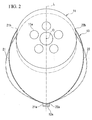
- connection members 13 is provided with a first connection plate 21 curved to protrude toward first side in the tire-circumferential direction, and a second connection plate 22 curved to protrude toward second side, in the side view. Respective first ends 21a and 22a of the first connection plate 21 and the second connection plate 22 of the connection member 13 are separately connected at the same position in the tire-circumferential direction and at positions different from each other in the tire-widthwise direction, on an inner circumferential face of the ring-shaped body 12.
- connection member 13 is axisymmetrical about an imaginary L connecting the respective first ends 21a and 22a of the first connection plate 21 and the second connection plate 22 to the axial line O in the side view and extending in the tire-radial direction.
- lengths of the first connection plate 21 and the second connection plate 22 are equal to each other, and the respective second ends 21b and 22b of the first connection plate 21 and the second connection plate 22 are separately connected, in the side view, from positions opposed to the respective first ends 21 a and 22a in the tire-circumferential direction at positions separated by the same angle (e.g., equal to or more than 90°, preferably equal to or more than 90° and equal to or less than 120°) to the first side and the second side in the tire-circumferential direction with respect to the axial line O, on an outer circumferential face of the installation disk 11.
- the same angle e.g., equal to or more than 90°, preferably equal to or more than 90° and equal to or less than 120°
- connection members 13 are separately arranged at positions of point symmetry with respect to the axial line O between the installation disk 11 and the ring-shaped body 12.
- the plurality (60 in the shown example) of connection members 13 are arranged in the tire-circumferential direction such that a plurality of first connection plates 21 are arranged at a first tire-widthwise position in the tire-circumferential direction and a plurality of second connection plates 22 are arranged at a second tire-widthwise position different from the first tire-widthwise position in the tire-circumferential direction. All the connection members 13 have the same shape and size.
- the first connection plate 21 and the second connection plate 22 have the same tire-widthwise (direction of the axial line O) size, that is, the same width (e.g., about 8 mm).
- the first connection plate 21 and the second connection plate 22 have the same thickness (e.g., about 2.5 mm).
- the first end 21 a and the second end 21 b of the first connection plate 21 and the first end 22a and the second end 22b of the second connection plate 22 have widths larger than those of parts positioned therebetween.
- the respective second ends 21b and 22b of the first connection plates 21 and the second connection plate 22 are formed of flat faces to come into contact with the outer circumferential face of the installation disk 11.
- the respective first ends 21a and 22a of the first connection plate 21 and the second connection plate 22 are formed of flat faces to come into contact with the inner circumferential face of the ring-shaped body 12, and have the largest thickness in the first connection plate 21 and the second connection plate 22.
- the ring-shaped body 12 is divided into a plurality of plate-shaped bodies 12a in the tire-circumferential direction.
- the ring-shaped body 12 is formed of metal.
- the respective first ends 21a and 22a of the first connection plate 21 and the second connection plate 22 are connected to a tire-widthwise direction inside of each plate-shaped body 12a.
- the respective first ends 21a and 22a of the first connection plate 21 and the second connection plate 22 are connected to each plate-shaped body 12a at positions deviating from the tire-widthwise center to the opposite vehicle side.
- Peripheral edges of the plate-shaped bodies 12a adjacent to each other in the tire-circumferential direction are close to each other or in contact with each other.
- the first connection plates 21 adjacent to each other in the tire-circumferential direction are opposed to each other in the tire-circumferential direction
- the second connection plates 22 adjacent to each other in the tire-circumferential direction are opposed to each other in the tire circumferential direction.
- the respective second ends 21b and 22b of the first connection plate 21 and the second connection plate 22 are separately connected to both tire-widthwise ends of the outer circumferential face of the installation disk 11.
- the first connection plate 21 of the second connection member 13 is opposed substantially parallel to the first connection plate 21 of the first connection member 13 in the tire-circumferential direction between the first connection plate 21 and the second connection plate 22 of the first connection member 13, and the second connection plate 22 of the first connection member 13 is opposed substantially parallel to the second connection plate 22 of the second connection member 13 in the tire-circumferential direction between the first connection plate 21 and the second connection plate 22 of the first connection member 13.
- the first connection plates 21 and the second connection plates 22 are formed of, for example, metal, resin, or the like having little hysteresis loss.
- the first connection plates 21 and the second connection plates 22 are formed of metal such as steel, stainless steel, and aluminum, the respective first ends 21a 22a of the first connection plate 21 and the second connection plate 22 and the respective second ends 21b and 22b of the first connection plate 21 and the second connection plate 22 are connected to the inner circumferential face of the ring-shaped body 12 and outer circumferential face of the installation disk 11 by welding.
- first connection plates 21 and the second connection plates 22 are formed of resin
- the respective first ends 21 a and 22a of the first connection plate 21 and the second connection plate 22 and the respective second ends 21 b and 22b of the first connection plate 21 and the second connection plate 22 are connected to the outer circumferential face of the installation disk 11 and the inner circumferential face of the ring-shaped body 12 by bonding with resin.
- connection members 13 are provided with the first connection plate 21 curved to protrude toward the first side in the tire-circumferential direction, and the second connection plate 22 curved to protrude toward the second side, in the side view.
- the installation disk 11 and the ring-shaped body 12 are relatively changed in position in the tire-radial direction, the tire-circumferential direction, or the tire-widthwise direction by external force applied to the non-pneumatic tire 10, it is possible to easily elastically deform the first connection plates 21 and the second connection plates 22 corresponding to the displacement. Accordingly, it is possible to provide the non-pneumatic tire 10 with flexibility, and it is possible to reliably secure satisfactory ride qualities.
- the respective first ends 21a and 22a of the first connection plate 21 and the second connection plate 22 of the connection member 13 are separately connected at the same position in the tire-circumferential direction and at positions different from each other in the tire-widthwise position on the inner circumferential face of the ring-shaped body 12.
- the plurality of first connection members 13 are arranged in the tire-circumferential direction such that the plurality of connection plates 21 are arranged at the first tire-widthwise position in the tire-circumferential direction and the plurality of second connection plates 22 are arranged at the second tire-widthwise position in the tire-circumferential direction. Accordingly, it is possible to suppress interference between the connection members 13 adjacent to each other in the tire-circumferential direction, and it is possible to prevent the number of arranged connection members 13 from being limited.
- connection member 13 Since the connection member 13 is axisymmetrical about the imaginary line L in the side view, it is possible to prevent a difference from occurring between a spring constant according to the first side in the tire-circumferential direction and a spring constant according to the second side in the non-pneumatic tire 10. Accordingly, with the non-pneumatic tire 10 being in contact with the ground, it is possible to suppress a difference between a spring constant according to the traveling direction and a spring constant according to the braking direction at the contact part of the tire 10 to the ground, and it is possible to reliably secure satisfactory handling qualities.
- the ring-shaped body 12 is divided in the tire-circumferential direction, it is possible to easily form the non-pneumatic tire 10.
- the ring-shaped body 12 is divided in the tire-circumferential direction, it is possible to improve flexibility of the ring-shaped body 12.
- first connection plates 21 and the second connection plates 22 are formed of metal or resin, it is possible to prevent hysteresis loss from occurring in the non-pneumatic tire 10 and it is possible to reduce rolling resistance as compared with the pneumatic tire.
- one first connection plate 21 and one second connection plate 22 are provided as the connection member 13, but instead, one connection member 13 may be provided with a plurality of first connection plates 21 and a plurality of second connection plates 22 at positions different from each other in the tire-widthwise direction.
- one connection member 13 may be provided with two first connection plates 21 at a distance from each other in the tire-widthwise direction, and two second connection plates 22 between such first connection plates 21 in the tire-widthwise direction.
- one second connection plate formed to be wide may be provided between two first connection plates 21, instead of providing two second connection plates 22.
- the plurality of connection members 13 may be arranged between the installation disk 11 and the ring-shaped body 12 in the tire-widthwise direction.
- the ring-shaped body 12 is divided into the plurality of plate-shaped bodies 12a in the tire-circumferential direction, but instead, a ring shaped body formed overall in one cylindrical shape may be employed.
- the materials for forming the first connection plates 21 and the second connection plates 22 are not limited to the first embodiment but may be appropriately modified.
- the respective second ends 21b and 22b of the first connection plate 21 and the second connection plate 22 may be separately connected, for example, at opposite positions with the axial line O interposed therebetween in the tire-radial direction on the outer circumferential face of the installation disk 11 instead of the first embodiment, or may be connected to positions opposed to the respective first ends 21a and 22a of the first connection plate 21 and the second connection plate 22 in the tire-radial direction on the outer circumferential face of the installation disk 11.
- a pneumatic tire (charged internal pressure: 230 kPa) with a size of 195/55 R16 of the conventional example was set as the assessment standard (100), non-pneumatic tires with the same size as the example and the comparative example were assessed on the basis of numerical indexes of weight, rolling resistance, ride qualities, handling qualities, spring constant (spring constant in the traveling direction) according to the first side in the tire-circumferential direction, and spring constant (spring constant in the braking direction) according to the second side.
- the non-pneumatic tire of the example employed the configurations shown in FIG. 1 to FIG.
- connection members, the ring-shaped bodies, and the installation disks of the non-pneumatic tires of the example and the comparative example were formed of stainless steel.
- the rolling resistance when rotating the tires of the example, the comparative example, and the conventional example at a speed of 80 km/h with the tire closely pressed onto a drum of a drum tester by a force of 4.0 kN, resistance applied to a drum shaft was measured.
- the spring constants were measured on the basis of force and movement (deformation of tire) when a rigid plate is pressed in a direction along the tire-circumferential direction among the directions, which are perpendicular to a direction of closely pressing the tire to the rigid plate, with the tires of the example, the comparative example, and the conventional example closely pressed onto the rigid plate by a force of 4.0 kN.
- the ride qualities and the handling qualities were assessed on the basis of the driver's feeling, when the tires of the example, the comparative example, and the conventional example were mounted on a vehicle and two people rode the vehicle to drive the vehicle.
- Table 1 shows that the weight and the rolling resistance are lower as the values thereof are smaller, the ride qualities and the handling qualities are more satisfactory as the values thereof are larger, and the spring constant is larger as the value thereof is larger.
- the non-pneumatic tire of the example it was confirmed that it was possible to suppress the increase in weight and to reduce rolling resistance as compared with the pneumatic tire of the conventional example.
- the ride qualities and the handling qualities in the non-pneumatic tire of the example, it was confirmed that it was possible to suppress a decrease in ride qualities and to keep the handling qualities equivalent to that of the pneumatic tire of the conventional example.
- the non-pneumatic tire of the example it was confirmed that it was possible to suppress an increase of the spring constants and to keep such spring constants equal to each other similar to the pneumatic tire of the conventional example.
- a difference between the spring constants is large and the handling qualities were thereby drastically decreased.
- the non-pneumatic tire 1 is provided with an installation disk 11 mounted on an axletree (not shown), a ring-shaped body 12 surrounding the installation disk 11 from the outside in the tire-radial direction, a plurality of connection members 13 connecting an outer circumferential face of the installation disk 11 to an inner circumferential face 12b of the ring-shaped body 12, a tread rubber 14 provided over the entire outer circumferential face of the ring-shaped body 12, and a reinforcement layer 15 provided between the ring-shaped body 12 and the tread rubber 14.
- the installation disk 11 has a circular shape in a side view of the non-pneumatic tire 1 from a direction of an axial line O, and a plurality of installation holes 11 a are formed at a radial center portion. For example, bolts are inserted into such installation holes 11a, and coupled to female screw portions formed in the axletree by screws, thereby mounting the installation disk 11 on the axletree.
- the installation disk 11 is formed of metal in a disk-shaped plate.
- the tread rubber 14 has a cylindrical shape, and integrally covers the entire outer circumferential face of the ring-shaped body 12.
- the thickness of the tread rubber 14 is, for example, about 10 mm.
- the reinforcement layer 15 has a configuration in which a plurality of steel cords is embedded abreast in a cylindrical rubber sheet.
- the reinforcement layer 15 may be formed integrally with the tread rubber 14 by embedding the plurality of steel cords side by side in the tread rubber 14.
- connection members 13 is provided with a first connection plate 21 curved to protrude toward a first side in the tire-circumferential direction, and a second connection plate 22 curved to protrude toward a second side, in the side view of the tire.
- Respective first ends 21a and 22a of the first connection plate 21 and the second connection plate 22 of one connection member 13 are separately connected at the same position in the tire-circumferential direction, on an inner circumferential face 12b of the ring-shaped body 12.
- the respective first ends 21a and 22a are separately connected at positions different from each other in the tire-widthwise direction H, on the inner circumferential face 12b of the ring-shaped body 12.
- each connection member 13 in the side view of the tire is axisymmetrical about an imaginary line L extending in the tire-radial direction through the tire-circumferential center of the connection member 13.
- the imaginary line L connects the respective first ends 21a and 22a of the first and the second connection plates 21 and 22 to the axial line O.
- lengths of the first and the second connection plates 21 and 22 are equal to each other, and the Respective second ends 21b and 22b of the first and the second connection plates 21 and 22 are separately connected, in the side view of the tire, from positions opposed to the respective first ends 21a and 22a in the tire-circumferential direction at positions separated by the same angle (e.g., equal to or more than 45° and equal to or less than 135°, preferably equal to or more than 90° and equal to less than 120°) to a first side and a second side in the tire-circumferential direction with respect to the axial line O, on an outer circumferential face of the installation disk 11.
- the same angle e.g., equal to or more than 45° and equal to or less than 135°, preferably equal to or more than 90° and equal to less than 120°
- connection members 13 are separately arranged at positions of point symmetry with respect to the axial line O between the installation disk 11 and the ring-shaped body 12.
- the plurality (60 in the shown example) of connection members 13 are arranged in the tire-circumferential direction such that a plurality of first connection plates 21 are arranged at a first tire-widthwise H position in the tire-circumferential direction and a plurality of second connection plates 22 are arranged at the other tire-widthwise H position different from the first tire-widthwise H position in the tire-circumferential direction. All the connection members 13 have the same shape and size.
- the first connection plates 21 adjacent to each other in the tire-circumferential direction are opposed substantially parallel to each other in the tire-circumferential direction
- the second connection plates 22 adjacent to each other in the tire-circumferential direction are also opposed substantially parallel to each other in the tire circumferential direction.
- the respective second ends 21b and 22b of the first and the second connection plates 21 and 22 are separately connected to both tire-widthwise H ends of the outer circumferential face of the installation disk 11.
- the first connection plate 21 and the second connection plate 22 have the same tire-widthwise H (direction in the axial line O) size, that is, the same width.
- the first connection plate 21 and the second connection plate 22 have the same thickness. Accordingly, the respective second ends 21 b and 22b of the first and the second connection plates 21 and 22 are connected so as to circumscribe the outer circumferential face of the installation disk 11.
- the ring-shaped body 12 is divided into a plurality of plate-shaped bodies 12a in the tire-circumferential direction.
- the plate-shaped bodies 12a are formed of metal. Peripheral edges of the plate-shaped bodies 12a adjacent to each other in the tire-circumferential direction are close to each other or in contact with each other.
- the respective first ends 21a and 22a of the first and the second connection plates 21 and 22 of one connection member 13 is connected to the plurality (3 in the shown example) of plate-shaped bodies 12a adjacent to each other in the tire-circumferential direction.
- the respective first ends 21 a and 22a of the first and the second connection plates 21 and 22 of one connection member 13 are connected at a position deviating from the tire-widthwise H center to the other end side (opposite to a vehicle side) on the inner circumferential face 12b of the ring-shaped body 12.
- the size of the plate-shaped body 12a in the tire-circumferential direction is, for example, about 1/10 of the size in the tire-widthwise direction H.
- An installation member 19 provided with a flat plate 19a and a block-shaped body 19b provided at the tire-circumferential direction center on a surface of the flat plate 19a is bonded onto a surface constituting the inner circumferential face 12b of the ring-shaped body 12 in the plurality of plate-shaped bodies 12a adjacent to each other in the tire-circumferential direction, and the plurality of plate-shaped bodies 12a adjacent to each other in the tire-circumferential direction are connected by the installation member 19.
- the installation member 19 is bonded to a position deviating from the tire-widthwise H center on the surface of the plate-shaped body 12a.
- the respective first ends 21a and 22a of the first and the second connection plates 21 and 22 of one connection member 13 are connected onto a surface of the block-shaped body 19b facing the inside in the tire-radial direction so as to circumscribe the surface of the block-shaped body 19b.
- the size of the installation disk 11 in the tire-widthwise direction H is about a half of the size of the ring-shaped body 12 in the tire-widthwise direction H. Accordingly, when the non-pneumatic tire 1 is mounted on the vehicle with one tire-widthwise H end positioned toward the vehicle and the other tire-widthwise H end positioned away from the vehicle, a space for housing a brake or the like is secured at a position toward the vehicle from the installation disk 11 in the inside of the ring-shaped body 12 in the tire-radial direction.
- the first connection plate 21 and the second connection plate 22 are formed of, for example, a metal or resin having little hysteresis loss.
- the first connection plate 21 and the second connection plate 22 are formed of a metal such as steel, stainless steel, or aluminum
- the first end 21a and the second end 21b of the first connection plate 21 and the first end 22a and the second end 22b of the second connection plate 22 are connected to the block-shaped body 19b (the inner circumferential face 12b side of the ring-shaped body 12) and the outer circumferential face of the installation disk 11 by welding or by coupling with coupling members.
- first connection plates 21 and the second connection plates 22 are formed of resin
- first end 21 a and the second end 21b of the first connection plate 21 and the first end 22a and the second end 22b of the second connection plate 22 are connected to the block-shaped body 19b (the inner circumferential face 12b side of the ring-shaped body 12) and the outer circumferential face of the installation disk 11 by bonding or by coupling with coupling members.
- the installation disk 11 and the ring-shaped body 12 are connected to each other by the plurality of connection members 13 arranged in the tire circumferential direction, and the non-pneumatic tire 1 does not have a solid structure in which the inside is filled with rubber. Accordingly, it is possible to suppress an increase in weight, hardness, and rolling resistance to secure satisfactory ride qualities and handling qualities, and it is possible to prevent a blowout from occurring.
- connection member 13 is provided with the first connection plate 21 curved to protrude toward the first side in the tire-circumferential direction, and the second connection plate 22 curved to protrude toward the second side, in the side view. Accordingly, when the installation disk 11 and the ring-shaped body 12 are relatively changed in position in the tire-radial direction, the tire-circumferential direction, or the tire-widthwise direction H, by external force applied to the non-pneumatic tire 1, it is possible to easily elastically deform the first connection plate 21 and the second connection plate 22 corresponding to the displacement. Accordingly, it is possible to provide the non-pneumatic tire 1 with flexibility, and it is possible to prevent vibration from being transmitted to the vehicle and to reliably secure satisfactory ride qualities.
- connection member 13 Since the connection member 13 is axisymmetrical about the imaginary line L in the side view, it is possible to prevent a difference from occurring between a spring constant according to the first side in the tire-circumferential direction and a spring constant according to the second side in the non-pneumatic tire 1. Accordingly, with the non-pneumatic tire 1 being in contact with the ground, it is possible to suppress a difference between a spring constant according to the traveling direction and a spring constant according to the braking direction at the contact part of the tire 1 to the ground, and it is possible to reliably secure satisfactory handling qualities.
- the ring-shaped body 12 is divided into the plurality of plate shaped bodies 12a in the tire-circumferential direction, it is possible to improve the flexibility of the ring-shaped body 12.
- the respective first ends 21a and 22a of the first and the second connection plates 21 and 22 of one connection member 13 is connected to the plurality of plate-shaped bodies 12a adjacent to each other in the tire-circumferential direction, the number of plate-shaped bodies 12a constituting the ring-shaped body 12 can be easily secured in a quantity sufficient to exhibit the above-described operational effects, and it is possible to easily distribute the contact pressure applied to the tread rubber 14 in the tire-circumferential direction, and to reliably suppress a difference in contact pressure within the contact face of the tire 1 to the ground.
- first and the second connection plates 21 and 22 of one connection member 13 are separately connected at the same position in the tire-circumferential direction and at positions different from each other in the tire-widthwise direction H, on the inner circumferential face 12b of the ring-shaped body 12. Since the plurality of connection members 13 are arranged in the tire-circumferential direction such that the plurality of first connection plates 21 are arranged at the first tire-widthwise position in the tire-circumferential direction and the plurality of second connection plates 22 are arranged at the second tire-widthwise position in the tire-circumferential direction, it is possible to suppress interference between the connection members 13 adjacent to each other in the tire-circumferential direction.
- first connection plates 21 and the second connection plates 22 may be formed of metal or resin, it is possible to substantially prevent hysteresis loss from occurring and to reduce rolling resistance as compared with the pneumatic tire.
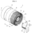
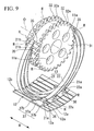
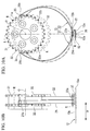
- a non-pneumatic tire according to a third embodiment of the invention will be described with reference to FIG. 8 to FIG. 10B , the same referential numerals and signs are given to the same parts as those of the second embodiment, the description thereof is not repeated, and only different parts will be described.
- the first end 21a and the second end 21b of the first connection plate 21 and the first end 22a and the second end 22b of the second connection plate 22 are rotatably supported around a rotation axial line R extending parallel to the tire-widthwise direction H.
- a plurality of first support protrusions 32 protruding toward the outside in the tire-radial direction are arranged at both tire-widthwise H ends on the outer circumferential face of the installation disk 31 at the same interval in the tire-circumferential direction, and each of the first support protrusions 32 is provided with a first bearing hole 32a penetrating in the tire-widthwise direction H.
- the first support protrusions 32 formed at both tire-widthwise H ends on the outer circumferential face of the installation disk 31 are opposed to each other in the tire-widthwise direction H, and the first bearing holes 32a formed in the first support protrusions 32 are positioned at the same axis as the rotation axial line R.
- the installation member 37 is provided with a flat plate 37a bonded to the plurality of plate-shaped bodies 12a, and a pair of second support protrusions 37b provided to protrude from the surface of the flat plate 37a at a distance from each other in the tire-widthwise direction H.
- the second support protrusion 37b is provided with a second bearing hole penetrating the tire-widthwise direction H.
- the second bearing holes are positioned at the same axis as the rotation axial line R.
- each of the respective second ends 21b and 22b of the first and second connection plates 21 and 22 is provided with a first shaft portion 35 extending parallel to the tire-widthwise direction H, and both ends of the first shaft portion 35 protrude more toward the outside of the tire-widthwise direction H than the connection plates 21 and 22.
- each of the respective first ends 21a and 22a of the first and the second connection plates 21 and 22 is connected through a second shaft portion 36 extending in the tire-widthwise direction H. Both ends of the second shaft portion 36 protrude more toward the outside of the tire-widthwise direction H than the first and the second connection plates 21 and 22.
- Both ends of the first shaft portion 35 are rotatably inserted into the first bearing holes 32a, and both ends of the second shaft portion 36 are rotatably inserted into the second bearing holes.
- connection parts the first end 21a and the second end 21b of the first connection plate 21 and the first end 22a and the second end 22b of the second connection plate 22 (hereinafter, referred to as connection parts) are rotatably supported around the rotation axial line R. Therefore, when the installation disk 31 and the ring-shaped body 12 are relatively changed in position in the tire-radial direction, the tire-circumferential direction, or the tire-widthwise direction H by external force applied to the non-pneumatic tire 2, it is possible to prevent the connection parts from being partially and greatly deformed, by rotating the connection parts of the first and the second connection plates 21 and 22 around the rotation axial line R.
- first and the second connection plates 21 and 22 are uniformly deformed overall with little bias, and it is possible to ease the load applied to the connection parts.
- the respective first ends 21a and 22a of the first and the second connection plates 21 and 22 of one connection member 13 are connected to the plurality of plate-shaped bodies 12a adjacent to each other in the tire-circumferential direction, and it is possible to further improve ride qualities and durability of the whole connection members 13.
- the number of arranged connection member 13 may be limited due to the reason of space.
- the number of arranged connection members 13 is limited as described above and the respective first ends 21a and 22a of the first and the second connection plates 21 and 22 of one connection member 13 are connected to one plate-shaped body 12a, the number of plate-shaped bodies 12a becomes too small and the above-described operational effects cannot be achieved.
- connection parts of the first and the second connection plates 21 and 22 are rotatably supported around the rotation axial line R, it is possible to secure the number of plate-shaped bodies 12a constituting the ring-shaped body 12 in a quantity sufficient to exhibit the above-described operational effects by connecting the respective first ends 21a and 22a of the first and the second connection plates 21 and 22 of one connection member 13 to the plurality of plate-shaped bodies 12a adjacent to each other in the tire-circumferential direction as described above, even when the number of arranged connection members 13 is small.
- connection member 13 since each of the respective first ends 21a and 22a of the first and the second connection plates 21 and 22 of one connection member 13 is connected to the plurality of plate-shaped bodies 12a adjacent to each other in the tire-circumferential direction, it is possible to secure a great number of plate-shaped bodies 12a irrespective of the number of arranged connection members 13.
- one first connection plate 21 and one second connection plate 22 are provided as the connection member 13, but instead, one connection member 13 may be provided with a plurality of first connection plates 21 and a plurality of second connection plates 22 at positions different from each other in the tire-widthwise direction H.
- the plurality of connection members 13 may be arranged between the installation disk 11 and the ring-shaped body 12 along the tire-widthwise direction H.
- a disk-shaped body has been described as the installation disk 11 or 31, for example, a ring-shaped body or the like may be employed instead.
- the materials for forming the first connection plates 21 and the second connection plates 22 are not limited to the third embodiment but may be appropriately modified.
- the respective second ends 21b and 22b of the first connection plate 21 and the second connection plate 22 may be separately connected, for example, at opposite positions with the axial line O interposed therebetween in the tire-radial direction on the outer circumferential face of the installation disk 11 or 31 instead of the third embodiment, or may be connected to the respective first ends 21a and 22a of the first connection plate 21 and the second connection plate 22 at positions opposed in the tire-radial direction on the outer circumferential face of the installation disk 11 or 31.
- the configuration has been described in which both groups of the respective first ends 21a and 22a of the first and the second connection plates 21 and 22 and the respective second ends 22b and 22b of the first and the second connection plates 21 and 22 is rotatably supported around the rotation axial line R, but at least one group of the first ends 21 a and 22a and the second ends 22b and 22b may be rotatably supported around the rotation axial line R.
- the respective first ends 21a and 22a of the first and the second connection plates 21 and 22 may be connected onto the inner circumferential face 12b of the ring-shaped body 12 at positions different from each other in the tire-circumferential direction.
- the non-pneumatic tire 1 shown in FIG. 5 to FIG. 7B was employed as the example 1, and the non-pneumatic tire 2 shown in FIG 8 to FIG. 10B was employed as the example 2.
- a configuration in which the respective first ends 21a and 22a of the first and the second connection plates 21 and 22 of one connection member 13 are connected to one plate-shaped body integrally formed of three plate-shaped bodies 12a in the non-pneumatic tire 1 of the example 1 was employed as the comparative example 1
- a configuration in which the respective first ends 21 a and 22a of the first and the second connection plates 21 and 22 of one connection member 13 are connected to one plate-shaped body integrally formed of three plate-shaped bodies 12a in the non-pneumatic 2 tire of the example 2 was employed as the comparative example 2.
- a pneumatic tire with internal pressure of 230 kPa was employed as the conventional example.
- the sizes of the tires of the example 1, the example 2, the comparative example 1, the comparative example 2, and the conventional example were all 195/55 R16.
- the tire-widthwise H size and thickness of the first and the second connection plates 21 and 22 were 18 mm and 3.0 mm, respectively, and the tire-circumferential size and thickness of the plate-shaped body 12a of the ring-shaped body 12 were 16 mm and 3.5 mm, respectively.
- the tire-widthwise H size and the thickness of the first and the second connection plates 21 and 22 were 18 mm and 2.0 mm, respectively, and the tire-circumferential size and the thickness of the plate-shaped body 12a of the ring-shaped body 12 were 16 mm and 3.5 mm, respectively.
- the first and the second connection plates 21 and 22 were formed of stainless steel, and the ring-shaped body 12 was formed of aluminum alloy.
- the conventional example was set as the assessment standard (100), and the non-pneumatic tire of the example 1 was assessed on the basis of numerical indexes of weight, rolling resistance, spring constant in the traveling direction, and spring constant in the braking direction.
- rolling resistance when rotating the tires at a speed of 80 km/h with the tire closely pressed onto a drum of a drum tester by a force of 4.0 kN, resistance applied to a drum shaft was measured.
- the spring constants were measured on the basis of force and movement (deformation of tire) when a rigid plate is pressed in a direction along the tire-circumferential direction among the directions, which are perpendicular to a direction of closely pressing the tire to the rigid plate, with the tires of the examples, the comparative examples, and the conventional example closely pressed onto the rigid plate by a force of 4.0 kN.
- the comparative example 1 was set as the assessment standard (100), and the non-pneumatic tires of the example 1, the example 2, and the comparative example 2 were assessed on the basis of numerical indexes of contact pressure standard deviation, ride qualities, and durability.
- the contact pressure standard deviation was assessed in a manner where the non-pneumatic tires of the comparative examples 1 and 2, and the examples 1 and 2 were closely pressed onto a flat plate through a pressure-sensitive paper by a force of 4.0 kN, thereby obtaining contact patterns of the tires to the ground, and the contact patterns were subjected to an image process.
- the ride qualities were assessed on the basis of the driver's feeling, when the tires were mounted on a vehicle and two persons rode the vehicle to drive the vehicle.
- the durability was assessed on the basis of the time when the tires of the comparative examples 1 and 2, and the examples 1 and 2 were rotated at a speed of 81 km/h with the tires closely pressed onto a drum of a drum tester by 5.2 kN and breakdown occurred.
Landscapes
- Engineering & Computer Science (AREA)
- Mechanical Engineering (AREA)
- Tires In General (AREA)
Abstract
Description
- The present invention relates to a non-pneumatic tire which need not be filled therein with pressurized air when used.
Priority is claimed on Japanese Patent Application No.2007-230238, filed September 5, 2007 2008-053917, filed March 4, 2008 - In the known pneumatic tire filled with pressurized air when used, the possibility of a blowout is an inevitable structural problem.
As a non-pneumatic tire capable of preventing a blowout from occurring, there is a so-called solid tire having a solid structure, which is filled therein with rubber, as described in Patent Document 1. - [Patent Document 1] Japanese Patent Application, First Publication No.
H06-293203 - The known non-pneumatic tire is heavy in weight and has great hardness and rolling resistance as compared with the pneumatic tire. Accordingly, the ride qualities and handling qualities drastically deteriorate, and thus the known non-pneumatic tire cannot be applied to general vehicles and there is a limit to the application range thereof.
- The invention has been made in consideration of such circumstances and an object of the invention is to provide a non-pneumatic tire capable of suppressing an increase in weight, hardness, and rolling resistance to secure satisfactory ride qualities and handling qualities, and to prevent blowout from occurring. Another object of the invention is to provide a non-pneumatic tire capable of securing good handling qualities and durability of, making distribution of contact pressure uniform, and of preventing a blowout from occurring.
- To solve the problems and to achieve such objects, according to the invention, there is provided a non-pneumatic tire including an installation disk that is mounted on an axletree, a ring-shaped body that surrounds the installation disk from the outside in a tire-radial direction, a plurality of connection members that connects an outer circumferential face of the installation disk and an inner circumferential face of the ring-shaped body, and a tread rubber that is disposed over an entire outer circumferential face of the ring-shaped body. The plurality of connection members have, in a side view of the non-pneumatic tire in a direction of the axial line, first connection plates curved to protrude toward first side in the tire-circumferential direction and second connection plates curved to protrude toward second side. Respective first ends of the first connection plate and the second connection plate of the connection member are separately connected at the same position in the tire-circumferential direction and at positions different from each other in the tire-widthwise direction, on an inner circumferential face of the ring-shaped body. The connection members are formed, in the side view, to be axisymmetrical about an imaginary line connecting respective first ends of the first connection plate and the second connection plate to the axial line and extending in the tire-radial direction. The plurality of connection members are arranged in the tire-circumferential direction, such that the plurality of first connection plates are arranged at a first tire-widthwise position in the tire-circumferential direction and the plurality of second connection plates are arranged at a second tire-widthwise position in the tire-circumferential direction.
In the invention, the non-pneumatic tire is configured by connecting the installation disk to the ring-shaped body through the connection members, and does not have a solid structure in which the inside is filled with rubber. Accordingly, it is possible to suppress an increase in weight, hardness, and rolling resistance to secure satisfactory ride qualities and handling qualities, and it is possible to prevent a blowout from occurring.
Each connection member is provided with the first connection plate curved to protrude toward first side in the tire-circumferential direction, and the second connection plate curved to protrude toward second side, in the side view. Accordingly, when the installation disk and the ring-shaped body are relatively changed in position in the tire-radial direction, the tire-circumferential direction, or the tire-widthwise direction by external force applied to the non-pneumatic tire, it is possible to easily elastically deform the first connection plates and the second connection plates corresponding to the displacement. Therefore, the non-pneumatic tire can be provided with flexibility, and it is possible to reliably secure satisfactory ride qualities.
Respective first ends of the first connection plate and the second connection plate of each connection member are separately connected at the same position in the tire-circumferential direction and at positions different from each other in the tire-widthwise direction, on the inner circumferential face of the ring-shaped body. A plurality of the connection members is arranged in the tire-circumferential direction such that the first connection plates are arranged at a first tire-widthwise position in the tire-circumferential direction and the second connection plates are arranged at a second tire-widthwise position in the tire-circumferential direction. Accordingly, it is possible to suppress interference between the connection members adjacent to each other in the tire-circumferential direction, and it is possible to prevent the number of arranged connection members from being limited.
Since each connection member is axisymmetrical about the imaginary line in the side view, it is possible to prevent a difference from occurring between a spring constant according to first side in the tire-circumferential direction and a spring constant according to second side in a non-pneumatic tire. Accordingly, with the non-pneumatic tire being in contact with the ground, it is possible to suppress a difference between a spring constant according to a traveling direction and a spring constant according to a braking direction at the contact part of the tire to the ground, and it is possible to reliably secure satisfactory handling qualities. - The ring-shaped body may be divided into a plurality of plate-shaped bodies in the tire-circumferential direction.
In this case, since the ring-shaped body is divided in the tire-circumferential direction, it is possible to easily form the non-pneumatic tire. For example, when a part of the ring-shaped body is damaged, only the damaged part may be replaced without replacing the whole ring-shaped body, and it is possible to easily maintain the tire.
As described above, since the ring-shaped body is divided in the tire-circumferential direction, it is possible to improve flexibility of the ring-shaped body. In addition, it is possible to easily deform the ring-shaped body corresponding to external force applied to the non-pneumatic tire, and it is possible to further reliably secure the satisfactory ride qualities. - The first connection plates and the second connection plates may be formed of a metal or resin.
In this case, it is possible to substantially prevent hysteresis loss from occurring, and it is possible to reduce rolling resistance as compared with a pneumatic tire. - To solve the problems and to achieve such objects, according to the invention, there is provided a non-pneumatic tire including an installation disk that is mounted on an axletree, a ring-shaped body that surrounds the installation disk from the outside in a tire-radial direction, a plurality of connection members that are arranged in a tire-circumferential direction and connect the installation disk to the ring-shaped body, and a tread rubber that is disposed over an entire outer circumferential face of the ring-shaped body. Each connection member has, in a side view of the tire in the axial direction, a first connection plate curved to protrude toward first side in the tire-circumferential direction and a second connection plate curved to protrude toward second side, and is formed to be axisymmetrical about an imaginary line extending in the tire-radial direction. The ring-shaped body is divided into a plurality of plate-shaped bodies in the tire-circumferential direction, respective first ends of the first connection plate and the second connection plate of one connection member is connected to a plurality of plate-shaped bodies adjacent to each other in the tire-circumferential direction.
In the invention, the non-pneumatic tire is configured by connecting the installation disk to the ring-shaped body through the plurality of connection members arranged in the tire-circumferential direction, and does not have a solid structure in which the inside is filled with rubber. Accordingly, it is possible to suppress an increase in weight, hardness, and rolling resistance to secure satisfactory ride qualities and handling qualities, and it is possible to prevent a blowout from occurring.
The connection member is provided, in the side view of the tire, with the first connection plate curved to protrude toward first side in the tire-circumferential direction, and the second connection plate curved to protrude toward second side. Accordingly, when the installation disk and the ring-shaped body are relatively changed in position in the tire-radial direction, the tire-circumferential direction, or the tire-widthwise direction by external force applied to the non-pneumatic tire, it is possible to easily elastically deform the first connection plates and the second connection plates. Therefore, it is possible to provide a non-pneumatic tire with flexibility, to prevent vibration from being transmitted to the vehicle, and to reliably secure satisfactory ride qualities.
Since each connection member is axisymmetrical about the imaginary line in the side view of the tire, it is possible to prevent a difference from occurring between a spring constant according to first side in the tire-circumferential direction and a spring constant according to second side in the non-pneumatic tire. Accordingly, with the non-pneumatic tire being in contact with the ground, it is possible to prevent a difference from occurring between a spring constant according to a traveling direction and a spring constant according to a braking direction at the contact part of the tire to the ground, and it is possible to reliably secure satisfactory handling qualities.
Since the ring-shaped body is divided into the plurality of plate-shaped bodies in the tire-circumferential direction, it is possible to improve flexibility of the ring-shaped body. Accordingly, it is possible to easily deform the ring-shaped body corresponding to the external force applied to the non-pneumatic tire, as well as to the first connection plates and the second connection plates. Therefore, it is possible to suppress a difference in contact pressure within the contact face of the tire to the ground, to further reliably secure satisfactory ride qualities, and to prevent side abrasion from occurring in the tread rubber.
As described above, since it is possible to easily deform the ring-shaped body, it is possible to drastically ease a load applied to the first and the second connection plates, and a load applied to the respective first ends of the first and the second connection plates connected to the ring-shaped body and the respective second ends of the first and the second connection plates connected to the installation disk, that is, the connection parts of the first and the second connection plates. Accordingly, it is possible to improve the durability of the whole connection members including the connection parts.
Since respective first ends of first and second connection plates of one connection member is connected to the plurality of plate-shaped bodies adjacent to each other in the tire-circumferential direction, the number of plate-shaped bodies constituting the ring-shaped body can be easily secured at a quantity large enough to exhibit the above-described operational effects, and it is possible to easily distribute the contact pressure applied to the tread rubber in the tire-circumferential direction, and to reliably suppress a difference in contact pressure within the contact face of the tire to the ground.
When a great number of plate-shaped bodies constituting the ring-shaped body are secured as described above, it is possible to prevent vibration occurring from the non-pneumatic tire at the time of driving. Accordingly, it is possible to secure satisfactory ride qualities, to suppress the load applied to the whole connection members and the tread rubber, and to improve durability of the whole non-pneumatic tire.
As described above; since the ring-shaped body is divided into the plurality of plate-shaped bodies in the tire-circumferential direction, it is possible to easily form a non-pneumatic tire. In addition, for example, when a part of the ring-shaped body is damaged, only the damaged part may be replaced without replacing the whole ring-shaped body, and it is possible to easily maintain the tire. - At least one group of respective first ends of the first connection plate and the second connection plate, and respective second ends of the first connection plate and the second connection plate connected to the outer circumferential face of the installation disk may be rotatably supported around the rotation axial line extending parallel to the tire-widthwise direction.
In this case, since at least one group of respective first ends of the first and the second connection plates and respective second ends of the first and the second connection plates is supported around the rotation axial line extending parallel to the tire-widthwise direction, at least one group is rotated around the rotation axial line and thus it is possible to suppress at least one group from being partially and greatly deformed when the installation disk and the ring-shaped body are relatively changed in position by the external force applied to the non-pneumatic tire as described above. The first and the second connection plates are uniformly deformed overall with little bias, and it is possible to ease the load applied to at least the one group. As described above, respective first ends of the first and the second connection plates of one connection member is connected to the plurality of plate-shaped bodies adjacent to each other in the tire-circumferential direction, and it is possible to further improve the ride qualities and durability of the whole connection members.
In the configuration in which at least one group of respective first ends of first connections plate and second connection plate and respective second ends of the first and the second connection plates is rotatably supported around the rotation axial line as described above, the number of arranged connection members may be limited due to the reason of space. When the number of arranged connection members is limited as described above and the respective first ends of the first and the second connection plates of one connection member are connected to one plate-shaped body, the number of plate-shaped bodies becomes too small and the above-described operational effects cannot be achieved.
That is, by employing the configuration in which at least one group of the respective first ends of the first and the second connection plates and the respective second ends of the first and the second connection plates is rotatably supported around the rotation axial line, it is possible to secure the number of plate-shaped bodies constituting the ring-shaped body in a quantity sufficient to exhibit the above-described operational effects by connecting the respective first ends of the first and the second connection plates of one connection member to the plurality of plate-shaped bodies adjacent to each other in the tire-circumferential direction as described above, even when the number of arranged connection members is small. That is, since the respective first ends of the first and the second connection plates of one connection member is connected to the plurality of plate-shaped bodies adjacent to each other in the tire-circumferential direction, it is possible to secure a great number of plate-shaped bodies irrespective of the number of arranged connection members. - Respective first ends of the first connection plate and the second connection plate of one connection member are separately connected at the same position in the tire-circumferential direction and at positions different from each other in the tire-widthwise direction, on an inner circumferential face of the ring-shaped body. The plurality of connection members may be arranged in the tire-circumferential direction such that the plurality of first connection plates are arranged at a first tire-widthwise position in the tire-circumferential direction and the plurality of second connection plates are arranged at a second tire-widthwise position in the tire-circumferential direction.
In this case, the respective first ends of the first and the second connection plates of one connection member are separately connected at the same position in the tire-circumferential direction and at position different from each other in the tire-widthwise direction, on the inner circumferential face of the ring-shaped body. Since the plurality of connection members are arranged in the tire-circumferential direction such that the plurality of first connection plates are arranged at the first tire-widthwise position in the tire-circumferential direction and the plurality of second connection plates are arranged at the second tire-widthwise position in the tire-circumferential direction, it is possible to suppress interference between the connection members adjacent to each other in the tire-circumferential direction. In addition, it is possible to further reliably prevent the number of arranged connection members from being limited, it is possible to further easily distribute the contact pressure applied to the tread rubber in the tire-widthwise direction, and it is possible to reliably prevent side abrasion from occurring in the tread rubber. - The first connection plates and the second connection plates may be formed of a metal or resin.
In this case, it is possible to substantially prevent hysteresis loss from occurring, and it is possible to reduce rolling resistance as compared with the pneumatic tire. - According to the invention, it is possible to suppress an increase in weight, hardness, and rolling resistance to secure satisfactory ride qualities and handling qualities, and it is possible to prevent a blowout from occurring. In addition, it is possible to secure satisfactory handling qualities and durability, to make distribution of contact pressure uniform, and to prevent a blowout from occurring.
-
-
FIG 1 is a schematic perspective view of disassembling a part of a non-pneumatic tire according to a first embodiment of the invention. -
FIG. 2 is a side view of a connection member and an installation disk in the non-pneumatic tire shown inFIG. 1 . -
FIG. 3 is a schematic perspective view illustrating a part of the non-pneumatic tire shown inFIG. 1 . -
FIG. 4 is a schematic perspective view illustrating a part of a non-pneumatic tire according to another embodiment of the invention. -
FIG. 5 is a schematic perspective view of disassembling a part of a non-pneumatic tire according to a second embodiment of the invention. -
FIG 6 is a schematic perspective view illustrating a part of the non-pneumatic tire shown inFIG. 5 . -
FIG. 7A is a front view of a connection member and an installation disk of the non-pneumatic tire shown inFIG. 5 , as viewed in a tire-widthwise direction. -
FIG. 7B is a side view ofFIG. 7A . -
FIG. 8 is a schematic perspective view of disassembling a part of a non-pneumatic tire according to a third embodiment of the invention. -
FIG. 9 is a schematic perspective view illustrating a part of the non-pneumatic tire shown inFIG. 8 . -
FIG. 10A is a front view of a connection member and an installation disk of the non-pneumatic tire shown inFIG. 8 , as viewed in a tire-widthwise direction. -
FIG. 10B is a side view ofFIG. 10A -
- 1, 2, 10: NON-PNEUMATIC TIRE
- 11,31: INSTALLATION DISK
- 12: RING-SHAPED BODY
- 12a: PLATE-SHAPED BODY
- 12b: INNER CIRCUMFERENTIAL FACE OF RING-SHAPED BODY
- 13: CONNECTION MEMBER
- 14: TREAD RUBBER
- 21: FIRST CONNECTION PLATE
- 22: SECOND CONNECTION PLATE
- 21a, 22a: FIRST END
- 21b, 22b: SECOND END
- L: IMAGINARY LINE
- O: AXIAL LINE
- H: TIRE-WIDTHWISE DIRECTION
- R: ROTATION AXIAL LINE
- Hereinafter, a non-pneumatic tire according to a first embodiment of the invention will be described with reference to
FIG. 1 to FIG. 3 .
Thenon-pneumatic tire 10 is provided with aninstallation disk 11 mounted on an axletree (not shown), a ring-shapedbody 12 surrounding theinstallation disk 11 from the outside in the radial direction, a plurality ofconnection members 13 connecting an outer circumferential face of theinstallation disk 11 to an inner circumferential face of the ring-shapedbody 12, and atread rubber 14 provided over the entire outer circumferential face of the ring-shapedbody 12. - The
installation disk 11 has a circular shape in a side view of thenon-pneumatic tire 10 from a direction of an axial line O, and a plurality ofinstallation holes 11a are formed at the radial center. For example, bolts are inserted into such installation holes 11 a, and are coupled to female screw portions formed in the axletree by screws, thereby mounting theinstallation disk 11 on the axletree. Theinstallation disk 11 is formed of metal.
Thetread rubber 14 has a cylindrical shape, and integrally covers the entire outer circumferential face of the ring-shapedbody 12. A thickness of thetread rubber 14 is, for example, about 10 mm. - Each of the
connection members 13 is provided with afirst connection plate 21 curved to protrude toward first side in the tire-circumferential direction, and asecond connection plate 22 curved to protrude toward second side, in the side view.
Respective first ends 21a and 22a of thefirst connection plate 21 and thesecond connection plate 22 of theconnection member 13 are separately connected at the same position in the tire-circumferential direction and at positions different from each other in the tire-widthwise direction, on an inner circumferential face of the ring-shapedbody 12. - As shown in
FIG. 2 , theconnection member 13 is axisymmetrical about an imaginary L connecting the respectivefirst ends first connection plate 21 and thesecond connection plate 22 to the axial line O in the side view and extending in the tire-radial direction.
That is, lengths of thefirst connection plate 21 and thesecond connection plate 22 are equal to each other, and the respective second ends 21b and 22b of thefirst connection plate 21 and thesecond connection plate 22 are separately connected, in the side view, from positions opposed to the respective first ends 21 a and 22a in the tire-circumferential direction at positions separated by the same angle (e.g., equal to or more than 90°, preferably equal to or more than 90° and equal to or less than 120°) to the first side and the second side in the tire-circumferential direction with respect to the axial line O, on an outer circumferential face of theinstallation disk 11. - The plurality of
connection members 13 are separately arranged at positions of point symmetry with respect to the axial line O between theinstallation disk 11 and the ring-shapedbody 12. The plurality (60 in the shown example) ofconnection members 13 are arranged in the tire-circumferential direction such that a plurality offirst connection plates 21 are arranged at a first tire-widthwise position in the tire-circumferential direction and a plurality ofsecond connection plates 22 are arranged at a second tire-widthwise position different from the first tire-widthwise position in the tire-circumferential direction. All theconnection members 13 have the same shape and size. - The
first connection plate 21 and thesecond connection plate 22 have the same tire-widthwise (direction of the axial line O) size, that is, the same width (e.g., about 8 mm). Thefirst connection plate 21 and thesecond connection plate 22 have the same thickness (e.g., about 2.5 mm).
In the shown example, thefirst end 21 a and thesecond end 21 b of thefirst connection plate 21 and thefirst end 22a and thesecond end 22b of thesecond connection plate 22 have widths larger than those of parts positioned therebetween. - The respective second ends 21b and 22b of the
first connection plates 21 and thesecond connection plate 22 are formed of flat faces to come into contact with the outer circumferential face of theinstallation disk 11. The respectivefirst ends first connection plate 21 and thesecond connection plate 22 are formed of flat faces to come into contact with the inner circumferential face of the ring-shapedbody 12, and have the largest thickness in thefirst connection plate 21 and thesecond connection plate 22. - In the first embodiment, the ring-shaped
body 12 is divided into a plurality of plate-shapedbodies 12a in the tire-circumferential direction. The ring-shapedbody 12 is formed of metal.
The respectivefirst ends first connection plate 21 and thesecond connection plate 22 are connected to a tire-widthwise direction inside of each plate-shapedbody 12a. In the shown example, the respectivefirst ends first connection plate 21 and thesecond connection plate 22 are connected to each plate-shapedbody 12a at positions deviating from the tire-widthwise center to the opposite vehicle side. - Peripheral edges of the plate-shaped
bodies 12a adjacent to each other in the tire-circumferential direction are close to each other or in contact with each other. Thefirst connection plates 21 adjacent to each other in the tire-circumferential direction are opposed to each other in the tire-circumferential direction, and thesecond connection plates 22 adjacent to each other in the tire-circumferential direction are opposed to each other in the tire circumferential direction. In the shown example, the respective second ends 21b and 22b of thefirst connection plate 21 and thesecond connection plate 22 are separately connected to both tire-widthwise ends of the outer circumferential face of theinstallation disk 11. - As described above, in a
first connection member 13 and asecond connection member 13 adjacent to each other in the tire-circumferential direction, thefirst connection plate 21 of thesecond connection member 13 is opposed substantially parallel to thefirst connection plate 21 of thefirst connection member 13 in the tire-circumferential direction between thefirst connection plate 21 and thesecond connection plate 22 of thefirst connection member 13, and thesecond connection plate 22 of thefirst connection member 13 is opposed substantially parallel to thesecond connection plate 22 of thesecond connection member 13 in the tire-circumferential direction between thefirst connection plate 21 and thesecond connection plate 22 of thefirst connection member 13. - In the first embodiment, the
first connection plates 21 and thesecond connection plates 22 are formed of, for example, metal, resin, or the like having little hysteresis loss.
When thefirst connection plates 21 and thesecond connection plates 22 are formed of metal such as steel, stainless steel, and aluminum, the respectivefirst ends 21afirst connection plate 21 and thesecond connection plate 22 and the respective second ends 21b and 22b of thefirst connection plate 21 and thesecond connection plate 22 are connected to the inner circumferential face of the ring-shapedbody 12 and outer circumferential face of theinstallation disk 11 by welding.
When thefirst connection plates 21 and thesecond connection plates 22 are formed of resin, the respective first ends 21 a and 22a of thefirst connection plate 21 and thesecond connection plate 22 and the respective second ends 21 b and 22b of thefirst connection plate 21 and thesecond connection plate 22 are connected to the outer circumferential face of theinstallation disk 11 and the inner circumferential face of the ring-shapedbody 12 by bonding with resin. - As described above, according to the
non-pneumatic tire 10 of the first embodiment, theinstallation disk 11 and the ring-shapedbody 12 are connected to each other by theconnection members 13, and thenon-pneumatic tire 10 does not have a solid structure in which the inside is filled with rubber. Accordingly, it is possible to suppress the increase in weight, hardness, and rolling resistance to secure satisfactory ride qualities and handling qualities, and it is possible to prevent a blowout from occurring.
Eachconnection member 13 is provided with thefirst connection plate 21 curved to protrude toward the first side in the tire-circumferential direction, and thesecond connection plate 22 curved to protrude toward the second side, in the side view. Accordingly, when theinstallation disk 11 and the ring-shapedbody 12 are relatively changed in position in the tire-radial direction, the tire-circumferential direction, or the tire-widthwise direction by external force applied to thenon-pneumatic tire 10, it is possible to easily elastically deform thefirst connection plates 21 and thesecond connection plates 22 corresponding to the displacement. Accordingly, it is possible to provide thenon-pneumatic tire 10 with flexibility, and it is possible to reliably secure satisfactory ride qualities. - The respective
first ends first connection plate 21 and thesecond connection plate 22 of theconnection member 13 are separately connected at the same position in the tire-circumferential direction and at positions different from each other in the tire-widthwise position on the inner circumferential face of the ring-shapedbody 12. The plurality offirst connection members 13 are arranged in the tire-circumferential direction such that the plurality ofconnection plates 21 are arranged at the first tire-widthwise position in the tire-circumferential direction and the plurality ofsecond connection plates 22 are arranged at the second tire-widthwise position in the tire-circumferential direction. Accordingly, it is possible to suppress interference between theconnection members 13 adjacent to each other in the tire-circumferential direction, and it is possible to prevent the number of arrangedconnection members 13 from being limited. - Since the
connection member 13 is axisymmetrical about the imaginary line L in the side view, it is possible to prevent a difference from occurring between a spring constant according to the first side in the tire-circumferential direction and a spring constant according to the second side in thenon-pneumatic tire 10. Accordingly, with thenon-pneumatic tire 10 being in contact with the ground, it is possible to suppress a difference between a spring constant according to the traveling direction and a spring constant according to the braking direction at the contact part of thetire 10 to the ground, and it is possible to reliably secure satisfactory handling qualities. - In the first embodiment, since the ring-shaped
body 12 is divided in the tire-circumferential direction, it is possible to easily form thenon-pneumatic tire 10. In addition, for example, when a part of the ring-shapedbody 12 is damaged, only the damaged part may be replaced without replacing the whole ring-shapedbody 12, and it is possible to easily maintain the tire.
Since the ring-shapedbody 12 is divided in the tire-circumferential direction, it is possible to improve flexibility of the ring-shapedbody 12. In addition, it is possible to easily deform the ring-shapedbody 12 corresponding to external force applied to thenon-pneumatic tire 10, and it is possible to further reliably secure the satisfactory ride qualities. - In the first embodiment, since the
first connection plates 21 and thesecond connection plates 22 are formed of metal or resin, it is possible to prevent hysteresis loss from occurring in thenon-pneumatic tire 10 and it is possible to reduce rolling resistance as compared with the pneumatic tire. - The technical scope of the invention is not limited to the embodiment, and can be variously modified in the scope which does not deviate from the concept of the invention.
For example, in the first embodiment, onefirst connection plate 21 and onesecond connection plate 22 are provided as theconnection member 13, but instead, oneconnection member 13 may be provided with a plurality offirst connection plates 21 and a plurality ofsecond connection plates 22 at positions different from each other in the tire-widthwise direction.
For example, as shown inFIG. 4 , oneconnection member 13 may be provided with twofirst connection plates 21 at a distance from each other in the tire-widthwise direction, and twosecond connection plates 22 between suchfirst connection plates 21 in the tire-widthwise direction.
In this configuration, one second connection plate formed to be wide may be provided between twofirst connection plates 21, instead of providing twosecond connection plates 22.
The plurality ofconnection members 13 may be arranged between theinstallation disk 11 and the ring-shapedbody 12 in the tire-widthwise direction. - In the first embodiment, the ring-shaped
body 12 is divided into the plurality of plate-shapedbodies 12a in the tire-circumferential direction, but instead, a ring shaped body formed overall in one cylindrical shape may be employed.
The materials for forming thefirst connection plates 21 and thesecond connection plates 22 are not limited to the first embodiment but may be appropriately modified.
The respective second ends 21b and 22b of thefirst connection plate 21 and thesecond connection plate 22 may be separately connected, for example, at opposite positions with the axial line O interposed therebetween in the tire-radial direction on the outer circumferential face of theinstallation disk 11 instead of the first embodiment, or may be connected to positions opposed to the respectivefirst ends first connection plate 21 and thesecond connection plate 22 in the tire-radial direction on the outer circumferential face of theinstallation disk 11. - Subsequently, a verification test of the above-described operational effects was conducted.
A pneumatic tire (charged internal pressure: 230 kPa) with a size of 195/55 R16 of the conventional example was set as the assessment standard (100), non-pneumatic tires with the same size as the example and the comparative example were assessed on the basis of numerical indexes of weight, rolling resistance, ride qualities, handling qualities, spring constant (spring constant in the traveling direction) according to the first side in the tire-circumferential direction, and spring constant (spring constant in the braking direction) according to the second side.
The non-pneumatic tire of the example employed the configurations shown inFIG. 1 to FIG. 3 , and the non-pneumatic tire of the comparative example employed a configuration in which thesecond connection plates 22 were not provided as compared with thenon-pneumatic tire 10 of the example, and the width of the first connection plates was larger (20 mm) than the width of thefirst connection plates 21 of thenon-pneumatic tire 10. The connection members, the ring-shaped bodies, and the installation disks of the non-pneumatic tires of the example and the comparative example were formed of stainless steel. - As for the rolling resistance, when rotating the tires of the example, the comparative example, and the conventional example at a speed of 80 km/h with the tire closely pressed onto a drum of a drum tester by a force of 4.0 kN, resistance applied to a drum shaft was measured.
The spring constants were measured on the basis of force and movement (deformation of tire) when a rigid plate is pressed in a direction along the tire-circumferential direction among the directions, which are perpendicular to a direction of closely pressing the tire to the rigid plate, with the tires of the example, the comparative example, and the conventional example closely pressed onto the rigid plate by a force of 4.0 kN.
The ride qualities and the handling qualities were assessed on the basis of the driver's feeling, when the tires of the example, the comparative example, and the conventional example were mounted on a vehicle and two people rode the vehicle to drive the vehicle. - The result is shown in Table 1.
This table shows that the weight and the rolling resistance are lower as the values thereof are smaller, the ride qualities and the handling qualities are more satisfactory as the values thereof are larger, and the spring constant is larger as the value thereof is larger. -
[Table 1] Weight Rolling Resistance Ride Qualities Handling Qualities Spring Constant in Traveling Direction Spring Constant in Braking Direction Example 103 80 98 100 102 102 Comparative Example 101 80 98 90 83 107 Conventional Example 100 100 100 100 100 100 - As a result, in the non-pneumatic tire of the example, it was confirmed that it was possible to suppress the increase in weight and to reduce rolling resistance as compared with the pneumatic tire of the conventional example.
As for the ride qualities and the handling qualities, in the non-pneumatic tire of the example, it was confirmed that it was possible to suppress a decrease in ride qualities and to keep the handling qualities equivalent to that of the pneumatic tire of the conventional example.
In the non-pneumatic tire of the example, it was confirmed that it was possible to suppress an increase of the spring constants and to keep such spring constants equal to each other similar to the pneumatic tire of the conventional example. Meanwhile, in the non-pneumatic tire of the comparative example, it was confirmed that a difference between the spring constants is large and the handling qualities were thereby drastically decreased. - Hereinafter, a non-pneumatic tire according to a second embodiment of the invention will be described with reference to
FIG. 5 to FIG 7B .
The non-pneumatic tire 1 is provided with aninstallation disk 11 mounted on an axletree (not shown), a ring-shapedbody 12 surrounding theinstallation disk 11 from the outside in the tire-radial direction, a plurality ofconnection members 13 connecting an outer circumferential face of theinstallation disk 11 to an innercircumferential face 12b of the ring-shapedbody 12, atread rubber 14 provided over the entire outer circumferential face of the ring-shapedbody 12, and areinforcement layer 15 provided between the ring-shapedbody 12 and thetread rubber 14. - The
installation disk 11 has a circular shape in a side view of the non-pneumatic tire 1 from a direction of an axial line O, and a plurality of installation holes 11 a are formed at a radial center portion. For example, bolts are inserted intosuch installation holes 11a, and coupled to female screw portions formed in the axletree by screws, thereby mounting theinstallation disk 11 on the axletree. Theinstallation disk 11 is formed of metal in a disk-shaped plate. - The
tread rubber 14 has a cylindrical shape, and integrally covers the entire outer circumferential face of the ring-shapedbody 12. The thickness of thetread rubber 14 is, for example, about 10 mm.
Thereinforcement layer 15 has a configuration in which a plurality of steel cords is embedded abreast in a cylindrical rubber sheet. Thereinforcement layer 15 may be formed integrally with thetread rubber 14 by embedding the plurality of steel cords side by side in thetread rubber 14. - Each of the
connection members 13 is provided with afirst connection plate 21 curved to protrude toward a first side in the tire-circumferential direction, and asecond connection plate 22 curved to protrude toward a second side, in the side view of the tire. Respective first ends 21a and 22a of thefirst connection plate 21 and thesecond connection plate 22 of oneconnection member 13 are separately connected at the same position in the tire-circumferential direction, on an innercircumferential face 12b of the ring-shapedbody 12. In the second embodiment, the respectivefirst ends circumferential face 12b of the ring-shapedbody 12. - As shown in
FIG. 7A , the shape of eachconnection member 13 in the side view of the tire is axisymmetrical about an imaginary line L extending in the tire-radial direction through the tire-circumferential center of theconnection member 13. In the shown example, the imaginary line L connects the respectivefirst ends second connection plates
That is, lengths of the first and thesecond connection plates second connection plates first ends installation disk 11. - The plurality of
connection members 13 are separately arranged at positions of point symmetry with respect to the axial line O between theinstallation disk 11 and the ring-shapedbody 12. The plurality (60 in the shown example) ofconnection members 13 are arranged in the tire-circumferential direction such that a plurality offirst connection plates 21 are arranged at a first tire-widthwise H position in the tire-circumferential direction and a plurality ofsecond connection plates 22 are arranged at the other tire-widthwise H position different from the first tire-widthwise H position in the tire-circumferential direction. All theconnection members 13 have the same shape and size. - The
first connection plates 21 adjacent to each other in the tire-circumferential direction are opposed substantially parallel to each other in the tire-circumferential direction, and thesecond connection plates 22 adjacent to each other in the tire-circumferential direction are also opposed substantially parallel to each other in the tire circumferential direction. In the shown example, the respective second ends 21b and 22b of the first and thesecond connection plates installation disk 11. - The
first connection plate 21 and thesecond connection plate 22 have the same tire-widthwise H (direction in the axial line O) size, that is, the same width. Thefirst connection plate 21 and thesecond connection plate 22 have the same thickness. Accordingly, the respective second ends 21 b and 22b of the first and thesecond connection plates installation disk 11. - In the second embodiment, the ring-shaped
body 12 is divided into a plurality of plate-shapedbodies 12a in the tire-circumferential direction. The plate-shapedbodies 12a are formed of metal. Peripheral edges of the plate-shapedbodies 12a adjacent to each other in the tire-circumferential direction are close to each other or in contact with each other. The respectivefirst ends second connection plates connection member 13 is connected to the plurality (3 in the shown example) of plate-shapedbodies 12a adjacent to each other in the tire-circumferential direction. In the shown example, the respective first ends 21 a and 22a of the first and thesecond connection plates connection member 13 are connected at a position deviating from the tire-widthwise H center to the other end side (opposite to a vehicle side) on the innercircumferential face 12b of the ring-shapedbody 12. The size of the plate-shapedbody 12a in the tire-circumferential direction is, for example, about 1/10 of the size in the tire-widthwise direction H. - An
installation member 19 provided with aflat plate 19a and a block-shapedbody 19b provided at the tire-circumferential direction center on a surface of theflat plate 19a is bonded onto a surface constituting the innercircumferential face 12b of the ring-shapedbody 12 in the plurality of plate-shapedbodies 12a adjacent to each other in the tire-circumferential direction, and the plurality of plate-shapedbodies 12a adjacent to each other in the tire-circumferential direction are connected by theinstallation member 19. Theinstallation member 19 is bonded to a position deviating from the tire-widthwise H center on the surface of the plate-shapedbody 12a. The respectivefirst ends second connection plates connection member 13 are connected onto a surface of the block-shapedbody 19b facing the inside in the tire-radial direction so as to circumscribe the surface of the block-shapedbody 19b. - In the shown example, the size of the
installation disk 11 in the tire-widthwise direction H is about a half of the size of the ring-shapedbody 12 in the tire-widthwise direction H. Accordingly, when the non-pneumatic tire 1 is mounted on the vehicle with one tire-widthwise H end positioned toward the vehicle and the other tire-widthwise H end positioned away from the vehicle, a space for housing a brake or the like is secured at a position toward the vehicle from theinstallation disk 11 in the inside of the ring-shapedbody 12 in the tire-radial direction. - In the second embodiment, the
first connection plate 21 and thesecond connection plate 22 are formed of, for example, a metal or resin having little hysteresis loss.
When thefirst connection plate 21 and thesecond connection plate 22 are formed of a metal such as steel, stainless steel, or aluminum, thefirst end 21a and thesecond end 21b of thefirst connection plate 21 and thefirst end 22a and thesecond end 22b of thesecond connection plate 22 are connected to the block-shapedbody 19b (the innercircumferential face 12b side of the ring-shaped body 12) and the outer circumferential face of theinstallation disk 11 by welding or by coupling with coupling members.
When thefirst connection plates 21 and thesecond connection plates 22 are formed of resin, thefirst end 21 a and thesecond end 21b of thefirst connection plate 21 and thefirst end 22a and thesecond end 22b of thesecond connection plate 22 are connected to the block-shapedbody 19b (the innercircumferential face 12b side of the ring-shaped body 12) and the outer circumferential face of theinstallation disk 11 by bonding or by coupling with coupling members. - As described above, according to the non-pneumatic tire 1 of the second embodiment, the
installation disk 11 and the ring-shapedbody 12 are connected to each other by the plurality ofconnection members 13 arranged in the tire circumferential direction, and the non-pneumatic tire 1 does not have a solid structure in which the inside is filled with rubber. Accordingly, it is possible to suppress an increase in weight, hardness, and rolling resistance to secure satisfactory ride qualities and handling qualities, and it is possible to prevent a blowout from occurring. - The
connection member 13 is provided with thefirst connection plate 21 curved to protrude toward the first side in the tire-circumferential direction, and thesecond connection plate 22 curved to protrude toward the second side, in the side view. Accordingly, when theinstallation disk 11 and the ring-shapedbody 12 are relatively changed in position in the tire-radial direction, the tire-circumferential direction, or the tire-widthwise direction H, by external force applied to the non-pneumatic tire 1, it is possible to easily elastically deform thefirst connection plate 21 and thesecond connection plate 22 corresponding to the displacement. Accordingly, it is possible to provide the non-pneumatic tire 1 with flexibility, and it is possible to prevent vibration from being transmitted to the vehicle and to reliably secure satisfactory ride qualities. - Since the
connection member 13 is axisymmetrical about the imaginary line L in the side view, it is possible to prevent a difference from occurring between a spring constant according to the first side in the tire-circumferential direction and a spring constant according to the second side in the non-pneumatic tire 1. Accordingly, with the non-pneumatic tire 1 being in contact with the ground, it is possible to suppress a difference between a spring constant according to the traveling direction and a spring constant according to the braking direction at the contact part of the tire 1 to the ground, and it is possible to reliably secure satisfactory handling qualities. - Since the ring-shaped
body 12 is divided into the plurality of plate shapedbodies 12a in the tire-circumferential direction, it is possible to improve the flexibility of the ring-shapedbody 12. In addition, it is possible to easily deform not only thefirst connection plates 21 and thesecond connection plates 22 but also the ring-shapedbody 12 corresponding to external force applied to the non-pneumatic tire 1. Accordingly, it is possible to suppress a difference in contact pressure within the contact face of the tire 1 to the ground, to further reliably secure satisfactory ride qualities, and to prevent side abrasion from occurring in thetread rubber 14. - As described above, since it is possible to easily deform the ring-shaped
body 12, it is possible to drastically ease not only the load applied to the first and thesecond connection plates first ends second connection plates body 12 and the respective second ends 21b and 22b of the first and thesecond connection plates installation disk 11, that is, the connection parts of the first and thesecond connection plates whole connection members 13 including the connection parts. - Since the respective
first ends second connection plates connection member 13 is connected to the plurality of plate-shapedbodies 12a adjacent to each other in the tire-circumferential direction, the number of plate-shapedbodies 12a constituting the ring-shapedbody 12 can be easily secured in a quantity sufficient to exhibit the above-described operational effects, and it is possible to easily distribute the contact pressure applied to thetread rubber 14 in the tire-circumferential direction, and to reliably suppress a difference in contact pressure within the contact face of the tire 1 to the ground. - When a great number of plate-shaped
bodies 12a constituting the ring-shapedbody 12 are secured as described above, it is possible to prevent vibration from occurring in the non-pneumatic tire 1 at the time of driving. Accordingly, it is possible to secure satisfactory ride qualities, to suppress the load applied to thewhole connection members 13 and thetread rubber 14 and to improve the durability of the whole non-pneumatic tire 1.
As described above, since the ring-shapedbody 12 is divided into the plurality of plate-shapedbodies 12a in the tire-circumferential direction, it is possible to easily form the non-pneumatic tire 1. In addition, for example, when a part of the ring-shapedbody 12 is damaged, only the damaged part may be replaced without replacing the whole ring-shapedbody 12, and it is possible to easily maintain the tire. - In addition, the respective
first ends second connection plates connection member 13 are separately connected at the same position in the tire-circumferential direction and at positions different from each other in the tire-widthwise direction H, on the innercircumferential face 12b of the ring-shapedbody 12. Since the plurality ofconnection members 13 are arranged in the tire-circumferential direction such that the plurality offirst connection plates 21 are arranged at the first tire-widthwise position in the tire-circumferential direction and the plurality ofsecond connection plates 22 are arranged at the second tire-widthwise position in the tire-circumferential direction, it is possible to suppress interference between theconnection members 13 adjacent to each other in the tire-circumferential direction. In addition, it is possible to further reliably prevent a limit from occurring in the number of arranged connection members, it is possible to further easily distribute the contact pressure applied to thetread rubber 14 in the tire-widthwise direction H, and it is possible to reliably prevent side abrasion from occurring in thetread rubber 14. - Since the
first connection plates 21 and thesecond connection plates 22 may be formed of metal or resin, it is possible to substantially prevent hysteresis loss from occurring and to reduce rolling resistance as compared with the pneumatic tire. - A non-pneumatic tire according to a third embodiment of the invention will be described with reference to
FIG. 8 to FIG. 10B , the same referential numerals and signs are given to the same parts as those of the second embodiment, the description thereof is not repeated, and only different parts will be described. - In the
non-pneumatic tire 2, thefirst end 21a and thesecond end 21b of thefirst connection plate 21 and thefirst end 22a and thesecond end 22b of thesecond connection plate 22 are rotatably supported around a rotation axial line R extending parallel to the tire-widthwise direction H.
A plurality offirst support protrusions 32 protruding toward the outside in the tire-radial direction are arranged at both tire-widthwise H ends on the outer circumferential face of theinstallation disk 31 at the same interval in the tire-circumferential direction, and each of thefirst support protrusions 32 is provided with afirst bearing hole 32a penetrating in the tire-widthwise direction H.
Thefirst support protrusions 32 formed at both tire-widthwise H ends on the outer circumferential face of theinstallation disk 31 are opposed to each other in the tire-widthwise direction H, and thefirst bearing holes 32a formed in thefirst support protrusions 32 are positioned at the same axis as the rotation axial line R. - The
installation member 37 is provided with aflat plate 37a bonded to the plurality of plate-shapedbodies 12a, and a pair ofsecond support protrusions 37b provided to protrude from the surface of theflat plate 37a at a distance from each other in the tire-widthwise direction H. Thesecond support protrusion 37b is provided with a second bearing hole penetrating the tire-widthwise direction H. The second bearing holes are positioned at the same axis as the rotation axial line R. - In the third embodiment, each of the respective second ends 21b and 22b of the first and
second connection plates first shaft portion 35 extending parallel to the tire-widthwise direction H, and both ends of thefirst shaft portion 35 protrude more toward the outside of the tire-widthwise direction H than theconnection plates first ends second connection plates second shaft portion 36 extending in the tire-widthwise direction H. Both ends of thesecond shaft portion 36 protrude more toward the outside of the tire-widthwise direction H than the first and thesecond connection plates
Both ends of thefirst shaft portion 35 are rotatably inserted into thefirst bearing holes 32a, and both ends of thesecond shaft portion 36 are rotatably inserted into the second bearing holes. - As described above, according to the
non-pneumatic tire 2 of the third embodiment, thefirst end 21a and thesecond end 21b of thefirst connection plate 21 and thefirst end 22a and thesecond end 22b of the second connection plate 22 (hereinafter, referred to as connection parts) are rotatably supported around the rotation axial line R. Therefore, when theinstallation disk 31 and the ring-shapedbody 12 are relatively changed in position in the tire-radial direction, the tire-circumferential direction, or the tire-widthwise direction H by external force applied to thenon-pneumatic tire 2, it is possible to prevent the connection parts from being partially and greatly deformed, by rotating the connection parts of the first and thesecond connection plates second connection plates first ends second connection plates connection member 13 are connected to the plurality of plate-shapedbodies 12a adjacent to each other in the tire-circumferential direction, and it is possible to further improve ride qualities and durability of thewhole connection members 13. - In the configuration in which the connection parts of the first and the
second connection plates connection member 13 may be limited due to the reason of space. When the number of arrangedconnection members 13 is limited as described above and the respectivefirst ends second connection plates connection member 13 are connected to one plate-shapedbody 12a, the number of plate-shapedbodies 12a becomes too small and the above-described operational effects cannot be achieved. - That is, by employing the configuration in which the connection parts of the first and the
second connection plates bodies 12a constituting the ring-shapedbody 12 in a quantity sufficient to exhibit the above-described operational effects by connecting the respectivefirst ends second connection plates connection member 13 to the plurality of plate-shapedbodies 12a adjacent to each other in the tire-circumferential direction as described above, even when the number of arrangedconnection members 13 is small. That is, since each of the respectivefirst ends second connection plates connection member 13 is connected to the plurality of plate-shapedbodies 12a adjacent to each other in the tire-circumferential direction, it is possible to secure a great number of plate-shapedbodies 12a irrespective of the number of arrangedconnection members 13. - The technical scope of the invention is not limited to the embodiment, and can be variously modified in the scope which does not deviate from the concept of the invention.
For example, in the third embodiment, onefirst connection plate 21 and onesecond connection plate 22 are provided as theconnection member 13, but instead, oneconnection member 13 may be provided with a plurality offirst connection plates 21 and a plurality ofsecond connection plates 22 at positions different from each other in the tire-widthwise direction H.
The plurality ofconnection members 13 may be arranged between theinstallation disk 11 and the ring-shapedbody 12 along the tire-widthwise direction H.
A disk-shaped body has been described as theinstallation disk - The materials for forming the
first connection plates 21 and thesecond connection plates 22 are not limited to the third embodiment but may be appropriately modified.
The respective second ends 21b and 22b of thefirst connection plate 21 and thesecond connection plate 22 may be separately connected, for example, at opposite positions with the axial line O interposed therebetween in the tire-radial direction on the outer circumferential face of theinstallation disk first ends first connection plate 21 and thesecond connection plate 22 at positions opposed in the tire-radial direction on the outer circumferential face of theinstallation disk - In the third embodiment, the configuration has been described in which both groups of the respective
first ends second connection plates second connection plates
Instead of the third embodiment, the respectivefirst ends second connection plates circumferential face 12b of the ring-shapedbody 12 at positions different from each other in the tire-circumferential direction. - Next, a verification test of the above-described operational effects was conducted.
The non-pneumatic tire 1 shown inFIG. 5 to FIG. 7B was employed as the example 1, and thenon-pneumatic tire 2 shown inFIG 8 to FIG. 10B was employed as the example 2.
A configuration in which the respectivefirst ends second connection plates connection member 13 are connected to one plate-shaped body integrally formed of three plate-shapedbodies 12a in the non-pneumatic tire 1 of the example 1 was employed as the comparative example 1, and a configuration in which the respective first ends 21 a and 22a of the first and thesecond connection plates connection member 13 are connected to one plate-shaped body integrally formed of three plate-shapedbodies 12a in the non-pneumatic 2 tire of the example 2 was employed as the comparative example 2.
A pneumatic tire with internal pressure of 230 kPa was employed as the conventional example.
The sizes of the tires of the example 1, the example 2, the comparative example 1, the comparative example 2, and the conventional example were all 195/55 R16. - In the example 1, the tire-widthwise H size and thickness of the first and the
second connection plates body 12a of the ring-shapedbody 12 were 16 mm and 3.5 mm, respectively.
In the example 2, the tire-widthwise H size and the thickness of the first and thesecond connection plates body 12a of the ring-shapedbody 12 were 16 mm and 3.5 mm, respectively.
In all of the example 1, the example 2, the comparative example 1, and the comparative example 2, the first and thesecond connection plates body 12 was formed of aluminum alloy. - First, the conventional example was set as the assessment standard (100), and the non-pneumatic tire of the example 1 was assessed on the basis of numerical indexes of weight, rolling resistance, spring constant in the traveling direction, and spring constant in the braking direction.
As for the rolling resistance, when rotating the tires at a speed of 80 km/h with the tire closely pressed onto a drum of a drum tester by a force of 4.0 kN, resistance applied to a drum shaft was measured.
The spring constants were measured on the basis of force and movement (deformation of tire) when a rigid plate is pressed in a direction along the tire-circumferential direction among the directions, which are perpendicular to a direction of closely pressing the tire to the rigid plate, with the tires of the examples, the comparative examples, and the conventional example closely pressed onto the rigid plate by a force of 4.0 kN. - The result is shown in Table 2.
This table shows that the weight and the rolling resistance are lower as the values thereof are smaller, and the spring constant is larger as the value thereof is larger. -
[Table 2] Weight Rolling Resistance Spring Constant in Traveling Direction Spring Constant in Braking Direction Example 1 103 80 102 102 Conventional Example 100 100 100 100 - As a result, in the non-pneumatic tire of the example 1, it was confirmed that it was possible to suppress an increase in weight and to reduce rolling resistance as compared with the pneumatic tire of the conventional example. In addition, it was confirmed that it was possible to suppress the increase of the spring constants and to keep such spring constants equal to each other similar to the pneumatic tire of the conventional example.
- Next, the comparative example 1 was set as the assessment standard (100), and the non-pneumatic tires of the example 1, the example 2, and the comparative example 2 were assessed on the basis of numerical indexes of contact pressure standard deviation, ride qualities, and durability.
The contact pressure standard deviation was assessed in a manner where the non-pneumatic tires of the comparative examples 1 and 2, and the examples 1 and 2 were closely pressed onto a flat plate through a pressure-sensitive paper by a force of 4.0 kN, thereby obtaining contact patterns of the tires to the ground, and the contact patterns were subjected to an image process.
The ride qualities were assessed on the basis of the driver's feeling, when the tires were mounted on a vehicle and two persons rode the vehicle to drive the vehicle.
The durability was assessed on the basis of the time when the tires of the comparative examples 1 and 2, and the examples 1 and 2 were rotated at a speed of 81 km/h with the tires closely pressed onto a drum of a drum tester by 5.2 kN and breakdown occurred. - The result is shown in Table 3.
This table shows that the contact pressure standard deviation is more satisfactory as the value thereof is smaller, and the ride qualities and the durability are more satisfactory as the values thereof are larger. -
[Table 3] Contact Pressure Standard Deviation Ride Qualities Durability Example 1 70 120 110 Example 2 66 125 130 Comparative Example 1 100 100 100 Comparative Example 2 97 105 120 - As a result, in comparison of the non-pneumatic tire 1 of the example 1 with the non-pneumatic tire of the comparative example 1 and in comparison of the
non-pneumatic tire 2 of the example 2 with the non-pneumatic tire of the comparative example 2, it was confirmed that it was possible to reduce the contact pressure distribution as compared with the comparative examples, and it was possible to improve the ride qualities and the durability as compared with the comparative examples.
In thenon-pneumatic tire 2 of the example 2, it was confirmed that it was possible to further reduce the contact pressure distribution and improve the ride qualities and the durability. - It is possible to suppress the increase in weight, hardness, and rolling resistance to secure satisfactory ride qualities and handling qualities, and it is possible to prevent a blowout from occurring. It is possible to make the distribution of contact pressure uniform, and to prevent a blowout from occurring.
Claims (6)
- A non-pneumatic tire comprising:an installation disk that is mounted on an axletree;a ring-shaped body that surrounds the installation disk from the outside in a tire-radial direction;a plurality of connection members that are arranged in a tire-circumferential direction and connect the installation disk to the ring-shaped body; anda tread rubber that is disposed over the entire outer circumferential face of the ring-shaped body,wherein each connection member has a first connection plate curved to protrude toward a first side in the tire-circumferential direction and a second connection plate curved to protrude toward a second side, and is formed to be axisymmetrical about an imaginary line extending in the tire-radial direction, andthe ring-shaped body is divided into a plurality of plate-shaped bodies in the tire-circumferential direction.
- The non-pneumatic tire according to Claim 1, wherein respective first ends of the first connection plate and the second connection plate of one connection member are connected to a plurality of plate-shaped bodies adjacent to each other in the tire-circumferential direction.
- The non-pneumatic tire according to Claim 1 or 2, wherein respective first ends of the first connection plate and the second connection plate of the connection member are separately connected at the same position in the tire-circumferential direction and at positions different from each other in the tire-widthwise direction, on an inner circumferential face of the ring-shaped body.
- The non-pneumatic tire according to any one of Claims 1 to 3, wherein the plurality of connection members are arranged in the tire-circumferential direction, such that the plurality of first connection plates are arranged at a first tire-widthwise position in the tire-circumferential direction and the plurality of second connection plates are arranged at a second tire-widthwise position in the tire-circumferential direction.
- The non-pneumatic tire according to Claim 1, wherein at least one group of respective first ends of the first connection plates and the second connection plates, and respective second ends of the first connection plates and the second connection plates is rotatably supported around a rotation axial line extending parallel to the tire-widthwise direction.
- The non-pneumatic tire according to any one of Claims 1 to 5, wherein the first connection plates and the second connection plates are formed of metal or resin.
Applications Claiming Priority (3)
| Application Number | Priority Date | Filing Date | Title |
|---|---|---|---|
| JP2007230238A JP5214198B2 (en) | 2007-09-05 | 2007-09-05 | Non pneumatic tire |
| JP2008053917 | 2008-03-04 | ||
| PCT/JP2008/066071 WO2009031650A1 (en) | 2007-09-05 | 2008-09-05 | Non-pneumatic tire |
Publications (3)
| Publication Number | Publication Date |
|---|---|
| EP2189301A1 true EP2189301A1 (en) | 2010-05-26 |
| EP2189301A4 EP2189301A4 (en) | 2011-09-14 |
| EP2189301B1 EP2189301B1 (en) | 2014-02-26 |
Family
ID=40428962
Family Applications (1)
| Application Number | Title | Priority Date | Filing Date |
|---|---|---|---|
| EP08829703.1A Not-in-force EP2189301B1 (en) | 2007-09-05 | 2008-09-05 | Non-pneumatic tire |
Country Status (3)
| Country | Link |
|---|---|
| US (1) | US8783310B2 (en) |
| EP (1) | EP2189301B1 (en) |
| WO (1) | WO2009031650A1 (en) |
Cited By (1)
| Publication number | Priority date | Publication date | Assignee | Title |
|---|---|---|---|---|
| CN107696785A (en) * | 2013-11-15 | 2018-02-16 | 株式会社普利司通 | Non-inflatable tyre |
Families Citing this family (21)
| Publication number | Priority date | Publication date | Assignee | Title |
|---|---|---|---|---|
| JP5436018B2 (en) * | 2008-07-09 | 2014-03-05 | 株式会社ブリヂストン | Non pneumatic tire |
| US9108470B2 (en) * | 2008-09-29 | 2015-08-18 | Polaris Industries Inc. | Run-flat device |
| US20110180194A1 (en) * | 2008-09-29 | 2011-07-28 | Resilient Technologies, Llc | Run-flat device |
| JP5879089B2 (en) * | 2011-10-20 | 2016-03-08 | 株式会社ブリヂストン | Non-pneumatic tire manufacturing method |
| US9573422B2 (en) | 2012-03-15 | 2017-02-21 | Polaris Industries Inc. | Non-pneumatic tire |
| JP6043582B2 (en) * | 2012-10-22 | 2016-12-14 | 株式会社ブリヂストン | Non pneumatic tire |
| JP6061625B2 (en) * | 2012-11-05 | 2017-01-18 | 株式会社ブリヂストン | Non pneumatic tire |
| CN103129307A (en) * | 2013-02-26 | 2013-06-05 | 刘恩均 | Energy-storage spoke flexible hub wheel |
| EP3007909A4 (en) | 2013-06-15 | 2017-03-01 | Ronald Thompson | Annular ring and non-pneumatic tire |
| WO2015047780A1 (en) | 2013-09-24 | 2015-04-02 | Bridgestone Americas Tire Operations, Llc | Tire with toroidal element |
| JP6152036B2 (en) * | 2013-10-21 | 2017-06-21 | 株式会社ブリヂストン | Non pneumatic tire |
| JP6303235B2 (en) * | 2013-10-22 | 2018-04-04 | 株式会社ブリヂストン | Non pneumatic tire |
| US10132721B2 (en) * | 2013-11-11 | 2018-11-20 | Sumitomo Rubber Industries, Ltd. | Device for measuring tread ring rigidity and method for measuring uniformity of tread ring |
| EP3086948B1 (en) | 2013-12-24 | 2020-03-11 | Bridgestone Americas Tire Operations, LLC | Airless tire construction having variable stiffness |
| WO2015194088A1 (en) | 2014-06-16 | 2015-12-23 | 株式会社ブリヂストン | Tire |
| EP3253591B1 (en) | 2015-02-04 | 2021-06-30 | Camso Inc. | Non-pneumatic tire and other annular devices |
| US11999419B2 (en) | 2015-12-16 | 2024-06-04 | Camso Inc. | Track system for traction of a vehicle |
| JP7004562B2 (en) * | 2017-12-14 | 2022-02-10 | Toyo Tire株式会社 | Non-pneumatic tires |
| USD1009724S1 (en) | 2018-08-23 | 2024-01-02 | Jelly Products Limited | Wheel side |
| US12043070B2 (en) * | 2018-12-28 | 2024-07-23 | Bridgestone Americas Tire Operations, Llc | Flexible metallic web elements for non-pneumatic tire |
| US11623472B2 (en) * | 2020-12-16 | 2023-04-11 | Htr Sa | Variable compliance metallic wheel comprising torque measuring device |
Family Cites Families (23)
| Publication number | Priority date | Publication date | Assignee | Title |
|---|---|---|---|---|
| DE247843C (en) * | ||||
| US1309839A (en) * | 1919-07-15 | Planograph co | ||
| FR342158A (en) * | 1904-04-02 | 1904-09-01 | Hugo Bremer | Elastic spring wheel in the form of an arc |
| GB191001176A (en) * | 1909-01-15 | 1910-03-03 | James Henry Van Arsdale | Improvements in Vehicle Wheels. |
| US1021440A (en) * | 1911-06-29 | 1912-03-26 | Rex E Arnold | Resilient wheel. |
| US1146654A (en) * | 1914-03-11 | 1915-07-13 | Henry F C Rietschel | Spring-wheel. |
| GB156482A (en) * | 1918-10-17 | 1921-07-14 | David Dewey Bohannon | Resilient wheel |
| JPS50113106A (en) | 1974-02-13 | 1975-09-05 | ||
| CA1239854A (en) | 1984-04-16 | 1988-08-02 | Uniroyal, Inc. | Non-pneumatic tire with supporting and cushioning members |
| US4921029A (en) * | 1984-04-16 | 1990-05-01 | The Uniroyal Goodrich Tire Company | Trapezoidal non-pneumatic tire with supporting and cushioning members |
| US4832098A (en) * | 1984-04-16 | 1989-05-23 | The Uniroyal Goodrich Tire Company | Non-pneumatic tire with supporting and cushioning members |
| JPS6293203A (en) | 1985-10-21 | 1987-04-28 | Agency Of Ind Science & Technol | Polybasic acid amine salt disinfectant |
| US4934425A (en) | 1988-03-23 | 1990-06-19 | Uniroyal Chemical Company, Inc. | Non-pneumatic tire |
| JPH04221201A (en) | 1990-12-21 | 1992-08-11 | Suzuki Motor Corp | Crawler traveling device |
| JP3092825B2 (en) | 1991-11-13 | 2000-09-25 | 輝 劉 | Wheel devices for automobile vehicles |
| JP3342734B2 (en) | 1993-04-06 | 2002-11-11 | 株式会社ブリヂストン | Solid tires for industrial vehicles |
| JPH0958209A (en) * | 1994-09-14 | 1997-03-04 | Yasushi Mera | Centipede wheel without tire blowout and with freely projecting and depressing pin for stopping slip |
| WO1998043833A1 (en) * | 1997-03-27 | 1998-10-08 | Compagnie Generale Des Etablissements Michelin - Michelin & Cie | Non-pneumatic ductile tyre |
| US6286572B1 (en) * | 2000-11-04 | 2001-09-11 | Ling-Lea Chen | Shock-absorbing safety wheel for motor vehicles |
| US20020096237A1 (en) * | 2001-01-23 | 2002-07-25 | Burhoe John Charles Alexander | Compliant rim and wheel and assembly |
| JP2003039901A (en) * | 2001-07-30 | 2003-02-13 | Kayaba Ind Co Ltd | Wheel with built-in suspension |
| US8091596B2 (en) | 2005-04-29 | 2012-01-10 | Big Tyre Pty Ltd | Non-pneumatic tyre assembly |
| JP2008030348A (en) * | 2006-07-31 | 2008-02-14 | Yokohama Rubber Co Ltd:The | Manufacturing method for tire/wheel assembly |
-
2008
- 2008-09-05 EP EP08829703.1A patent/EP2189301B1/en not_active Not-in-force
- 2008-09-05 US US12/676,779 patent/US8783310B2/en active Active
- 2008-09-05 WO PCT/JP2008/066071 patent/WO2009031650A1/en not_active Ceased
Cited By (1)
| Publication number | Priority date | Publication date | Assignee | Title |
|---|---|---|---|---|
| CN107696785A (en) * | 2013-11-15 | 2018-02-16 | 株式会社普利司通 | Non-inflatable tyre |
Also Published As
| Publication number | Publication date |
|---|---|
| EP2189301A4 (en) | 2011-09-14 |
| US20100218869A1 (en) | 2010-09-02 |
| US8783310B2 (en) | 2014-07-22 |
| WO2009031650A1 (en) | 2009-03-12 |
| EP2189301B1 (en) | 2014-02-26 |
Similar Documents
| Publication | Publication Date | Title |
|---|---|---|
| EP2189301B1 (en) | Non-pneumatic tire | |
| EP2305489B1 (en) | Non-pneumatic tire | |
| EP2772367B1 (en) | Non-pneumatic tire with reinforcing member having plate wire structure | |
| CN105774406B (en) | Solid tyre | |
| US11167593B2 (en) | Reinforcement structure for non-pneumatic wheel | |
| US20120241062A1 (en) | Tension-based non-pneumatic tire | |
| CN109466250B (en) | Pneumatic tires | |
| JP5401157B2 (en) | Non pneumatic tire | |
| CN105793063A (en) | Airless tire | |
| JP5401156B2 (en) | Non pneumatic tire | |
| JP5377004B2 (en) | Non pneumatic tire | |
| JP5401155B2 (en) | Non pneumatic tire | |
| CN112455163B (en) | Inflation-free tyre | |
| JP5416993B2 (en) | Non pneumatic tire | |
| EP4046821B1 (en) | Airless tire | |
| US20210070104A1 (en) | Non-pneumatic tire | |
| CN212667037U (en) | Novel belted layer tire | |
| EP4046823B1 (en) | Airless tire | |
| EP4046822B1 (en) | Airless tire | |
| CN114683770B (en) | Inflation-free tyre | |
| EP4393721B1 (en) | Non-pneumatic tire | |
| JP2025171529A (en) | Airless tire structure | |
| EP1717062B1 (en) | Elastic wheel and method of manufacturing the same | |
| CN119317543A (en) | Self-supporting spoke structure for non-pneumatic tires | |
| CN112677708A (en) | Non-pneumatic tire |
Legal Events
| Date | Code | Title | Description |
|---|---|---|---|
| PUAI | Public reference made under article 153(3) epc to a published international application that has entered the european phase |
Free format text: ORIGINAL CODE: 0009012 |
|
| 17P | Request for examination filed |
Effective date: 20100315 |
|
| AK | Designated contracting states |
Kind code of ref document: A1 Designated state(s): AT BE BG CH CY CZ DE DK EE ES FI FR GB GR HR HU IE IS IT LI LT LU LV MC MT NL NO PL PT RO SE SI SK TR |
|
| AX | Request for extension of the european patent |
Extension state: AL BA MK RS |
|
| DAX | Request for extension of the european patent (deleted) | ||
| A4 | Supplementary search report drawn up and despatched |
Effective date: 20110818 |
|
| RIC1 | Information provided on ipc code assigned before grant |
Ipc: B60C 7/00 20060101ALI20110811BHEP Ipc: B60B 9/02 20060101AFI20110811BHEP Ipc: B60B 9/06 20060101ALI20110811BHEP Ipc: B60B 9/26 20060101ALI20110811BHEP Ipc: B60C 7/18 20060101ALI20110811BHEP |
|
| 17Q | First examination report despatched |
Effective date: 20120508 |
|
| REG | Reference to a national code |
Ref country code: DE Ref legal event code: R079 Ref document number: 602008030481 Country of ref document: DE Free format text: PREVIOUS MAIN CLASS: B60B0009020000 Ipc: B60C0007220000 |
|
| RIC1 | Information provided on ipc code assigned before grant |
Ipc: B60C 7/18 20060101ALI20130415BHEP Ipc: B60C 7/22 20060101AFI20130415BHEP Ipc: B60B 9/26 20060101ALI20130415BHEP |
|
| GRAP | Despatch of communication of intention to grant a patent |
Free format text: ORIGINAL CODE: EPIDOSNIGR1 |
|
| INTG | Intention to grant announced |
Effective date: 20130528 |
|
| GRAP | Despatch of communication of intention to grant a patent |
Free format text: ORIGINAL CODE: EPIDOSNIGR1 |
|
| INTG | Intention to grant announced |
Effective date: 20130903 |
|
| GRAS | Grant fee paid |
Free format text: ORIGINAL CODE: EPIDOSNIGR3 |
|
| GRAA | (expected) grant |
Free format text: ORIGINAL CODE: 0009210 |
|
| AK | Designated contracting states |
Kind code of ref document: B1 Designated state(s): AT BE BG CH CY CZ DE DK EE ES FI FR GB GR HR HU IE IS IT LI LT LU LV MC MT NL NO PL PT RO SE SI SK TR |
|
| REG | Reference to a national code |
Ref country code: GB Ref legal event code: FG4D |
|
| REG | Reference to a national code |
Ref country code: CH Ref legal event code: EP |
|
| REG | Reference to a national code |
Ref country code: AT Ref legal event code: REF Ref document number: 653348 Country of ref document: AT Kind code of ref document: T Effective date: 20140315 |
|
| REG | Reference to a national code |
Ref country code: IE Ref legal event code: FG4D |
|
| REG | Reference to a national code |
Ref country code: DE Ref legal event code: R096 Ref document number: 602008030481 Country of ref document: DE Effective date: 20140410 |
|
| REG | Reference to a national code |
Ref country code: NL Ref legal event code: VDEP Effective date: 20140226 |
|
| REG | Reference to a national code |
Ref country code: AT Ref legal event code: MK05 Ref document number: 653348 Country of ref document: AT Kind code of ref document: T Effective date: 20140226 |
|
| REG | Reference to a national code |
Ref country code: LT Ref legal event code: MG4D |
|
| PG25 | Lapsed in a contracting state [announced via postgrant information from national office to epo] |
Ref country code: LT Free format text: LAPSE BECAUSE OF FAILURE TO SUBMIT A TRANSLATION OF THE DESCRIPTION OR TO PAY THE FEE WITHIN THE PRESCRIBED TIME-LIMIT Effective date: 20140226 Ref country code: IS Free format text: LAPSE BECAUSE OF FAILURE TO SUBMIT A TRANSLATION OF THE DESCRIPTION OR TO PAY THE FEE WITHIN THE PRESCRIBED TIME-LIMIT Effective date: 20140626 Ref country code: NO Free format text: LAPSE BECAUSE OF FAILURE TO SUBMIT A TRANSLATION OF THE DESCRIPTION OR TO PAY THE FEE WITHIN THE PRESCRIBED TIME-LIMIT Effective date: 20140526 |
|
| PG25 | Lapsed in a contracting state [announced via postgrant information from national office to epo] |
Ref country code: CY Free format text: LAPSE BECAUSE OF FAILURE TO SUBMIT A TRANSLATION OF THE DESCRIPTION OR TO PAY THE FEE WITHIN THE PRESCRIBED TIME-LIMIT Effective date: 20140226 Ref country code: PT Free format text: LAPSE BECAUSE OF FAILURE TO SUBMIT A TRANSLATION OF THE DESCRIPTION OR TO PAY THE FEE WITHIN THE PRESCRIBED TIME-LIMIT Effective date: 20140626 Ref country code: AT Free format text: LAPSE BECAUSE OF FAILURE TO SUBMIT A TRANSLATION OF THE DESCRIPTION OR TO PAY THE FEE WITHIN THE PRESCRIBED TIME-LIMIT Effective date: 20140226 Ref country code: NL Free format text: LAPSE BECAUSE OF FAILURE TO SUBMIT A TRANSLATION OF THE DESCRIPTION OR TO PAY THE FEE WITHIN THE PRESCRIBED TIME-LIMIT Effective date: 20140226 Ref country code: SE Free format text: LAPSE BECAUSE OF FAILURE TO SUBMIT A TRANSLATION OF THE DESCRIPTION OR TO PAY THE FEE WITHIN THE PRESCRIBED TIME-LIMIT Effective date: 20140226 Ref country code: FI Free format text: LAPSE BECAUSE OF FAILURE TO SUBMIT A TRANSLATION OF THE DESCRIPTION OR TO PAY THE FEE WITHIN THE PRESCRIBED TIME-LIMIT Effective date: 20140226 |
|
| PG25 | Lapsed in a contracting state [announced via postgrant information from national office to epo] |
Ref country code: HR Free format text: LAPSE BECAUSE OF FAILURE TO SUBMIT A TRANSLATION OF THE DESCRIPTION OR TO PAY THE FEE WITHIN THE PRESCRIBED TIME-LIMIT Effective date: 20140226 Ref country code: BE Free format text: LAPSE BECAUSE OF FAILURE TO SUBMIT A TRANSLATION OF THE DESCRIPTION OR TO PAY THE FEE WITHIN THE PRESCRIBED TIME-LIMIT Effective date: 20140226 Ref country code: LV Free format text: LAPSE BECAUSE OF FAILURE TO SUBMIT A TRANSLATION OF THE DESCRIPTION OR TO PAY THE FEE WITHIN THE PRESCRIBED TIME-LIMIT Effective date: 20140226 |
|
| PG25 | Lapsed in a contracting state [announced via postgrant information from national office to epo] |
Ref country code: RO Free format text: LAPSE BECAUSE OF FAILURE TO SUBMIT A TRANSLATION OF THE DESCRIPTION OR TO PAY THE FEE WITHIN THE PRESCRIBED TIME-LIMIT Effective date: 20140226 Ref country code: DK Free format text: LAPSE BECAUSE OF FAILURE TO SUBMIT A TRANSLATION OF THE DESCRIPTION OR TO PAY THE FEE WITHIN THE PRESCRIBED TIME-LIMIT Effective date: 20140226 Ref country code: EE Free format text: LAPSE BECAUSE OF FAILURE TO SUBMIT A TRANSLATION OF THE DESCRIPTION OR TO PAY THE FEE WITHIN THE PRESCRIBED TIME-LIMIT Effective date: 20140226 Ref country code: CZ Free format text: LAPSE BECAUSE OF FAILURE TO SUBMIT A TRANSLATION OF THE DESCRIPTION OR TO PAY THE FEE WITHIN THE PRESCRIBED TIME-LIMIT Effective date: 20140226 |
|
| REG | Reference to a national code |
Ref country code: DE Ref legal event code: R097 Ref document number: 602008030481 Country of ref document: DE |
|
| PG25 | Lapsed in a contracting state [announced via postgrant information from national office to epo] |
Ref country code: SK Free format text: LAPSE BECAUSE OF FAILURE TO SUBMIT A TRANSLATION OF THE DESCRIPTION OR TO PAY THE FEE WITHIN THE PRESCRIBED TIME-LIMIT Effective date: 20140226 Ref country code: PL Free format text: LAPSE BECAUSE OF FAILURE TO SUBMIT A TRANSLATION OF THE DESCRIPTION OR TO PAY THE FEE WITHIN THE PRESCRIBED TIME-LIMIT Effective date: 20140226 Ref country code: ES Free format text: LAPSE BECAUSE OF FAILURE TO SUBMIT A TRANSLATION OF THE DESCRIPTION OR TO PAY THE FEE WITHIN THE PRESCRIBED TIME-LIMIT Effective date: 20140226 |
|
| PLBE | No opposition filed within time limit |
Free format text: ORIGINAL CODE: 0009261 |
|
| STAA | Information on the status of an ep patent application or granted ep patent |
Free format text: STATUS: NO OPPOSITION FILED WITHIN TIME LIMIT |
|
| 26N | No opposition filed |
Effective date: 20141127 |
|
| REG | Reference to a national code |
Ref country code: DE Ref legal event code: R097 Ref document number: 602008030481 Country of ref document: DE Effective date: 20141127 |
|
| PG25 | Lapsed in a contracting state [announced via postgrant information from national office to epo] |
Ref country code: MC Free format text: LAPSE BECAUSE OF FAILURE TO SUBMIT A TRANSLATION OF THE DESCRIPTION OR TO PAY THE FEE WITHIN THE PRESCRIBED TIME-LIMIT Effective date: 20140226 Ref country code: LU Free format text: LAPSE BECAUSE OF FAILURE TO SUBMIT A TRANSLATION OF THE DESCRIPTION OR TO PAY THE FEE WITHIN THE PRESCRIBED TIME-LIMIT Effective date: 20140905 |
|
| REG | Reference to a national code |
Ref country code: CH Ref legal event code: PL |
|
| PG25 | Lapsed in a contracting state [announced via postgrant information from national office to epo] |
Ref country code: SI Free format text: LAPSE BECAUSE OF FAILURE TO SUBMIT A TRANSLATION OF THE DESCRIPTION OR TO PAY THE FEE WITHIN THE PRESCRIBED TIME-LIMIT Effective date: 20140226 |
|
| REG | Reference to a national code |
Ref country code: IE Ref legal event code: MM4A |
|
| PG25 | Lapsed in a contracting state [announced via postgrant information from national office to epo] |
Ref country code: LI Free format text: LAPSE BECAUSE OF NON-PAYMENT OF DUE FEES Effective date: 20140930 Ref country code: CH Free format text: LAPSE BECAUSE OF NON-PAYMENT OF DUE FEES Effective date: 20140930 |
|
| PG25 | Lapsed in a contracting state [announced via postgrant information from national office to epo] |
Ref country code: IE Free format text: LAPSE BECAUSE OF NON-PAYMENT OF DUE FEES Effective date: 20140905 |
|
| PG25 | Lapsed in a contracting state [announced via postgrant information from national office to epo] |
Ref country code: BG Free format text: LAPSE BECAUSE OF FAILURE TO SUBMIT A TRANSLATION OF THE DESCRIPTION OR TO PAY THE FEE WITHIN THE PRESCRIBED TIME-LIMIT Effective date: 20140226 |
|
| PG25 | Lapsed in a contracting state [announced via postgrant information from national office to epo] |
Ref country code: MT Free format text: LAPSE BECAUSE OF FAILURE TO SUBMIT A TRANSLATION OF THE DESCRIPTION OR TO PAY THE FEE WITHIN THE PRESCRIBED TIME-LIMIT Effective date: 20140226 Ref country code: GR Free format text: LAPSE BECAUSE OF FAILURE TO SUBMIT A TRANSLATION OF THE DESCRIPTION OR TO PAY THE FEE WITHIN THE PRESCRIBED TIME-LIMIT Effective date: 20140527 |
|
| PG25 | Lapsed in a contracting state [announced via postgrant information from national office to epo] |
Ref country code: TR Free format text: LAPSE BECAUSE OF FAILURE TO SUBMIT A TRANSLATION OF THE DESCRIPTION OR TO PAY THE FEE WITHIN THE PRESCRIBED TIME-LIMIT Effective date: 20140226 Ref country code: HU Free format text: LAPSE BECAUSE OF FAILURE TO SUBMIT A TRANSLATION OF THE DESCRIPTION OR TO PAY THE FEE WITHIN THE PRESCRIBED TIME-LIMIT; INVALID AB INITIO Effective date: 20080905 |
|
| REG | Reference to a national code |
Ref country code: FR Ref legal event code: PLFP Year of fee payment: 9 |
|
| REG | Reference to a national code |
Ref country code: FR Ref legal event code: PLFP Year of fee payment: 10 |
|
| REG | Reference to a national code |
Ref country code: FR Ref legal event code: PLFP Year of fee payment: 11 |
|
| PGFP | Annual fee paid to national office [announced via postgrant information from national office to epo] |
Ref country code: IT Payment date: 20190925 Year of fee payment: 12 |
|
| PGFP | Annual fee paid to national office [announced via postgrant information from national office to epo] |
Ref country code: GB Payment date: 20190925 Year of fee payment: 12 |
|
| PGFP | Annual fee paid to national office [announced via postgrant information from national office to epo] |
Ref country code: DE Payment date: 20200925 Year of fee payment: 13 |
|
| GBPC | Gb: european patent ceased through non-payment of renewal fee |
Effective date: 20200905 |
|
| PG25 | Lapsed in a contracting state [announced via postgrant information from national office to epo] |
Ref country code: GB Free format text: LAPSE BECAUSE OF NON-PAYMENT OF DUE FEES Effective date: 20200905 |
|
| PG25 | Lapsed in a contracting state [announced via postgrant information from national office to epo] |
Ref country code: IT Free format text: LAPSE BECAUSE OF NON-PAYMENT OF DUE FEES Effective date: 20200905 |
|
| REG | Reference to a national code |
Ref country code: DE Ref legal event code: R119 Ref document number: 602008030481 Country of ref document: DE |
|
| PG25 | Lapsed in a contracting state [announced via postgrant information from national office to epo] |
Ref country code: DE Free format text: LAPSE BECAUSE OF NON-PAYMENT OF DUE FEES Effective date: 20220401 |
|
| PGFP | Annual fee paid to national office [announced via postgrant information from national office to epo] |
Ref country code: FR Payment date: 20220922 Year of fee payment: 15 |
|
| P01 | Opt-out of the competence of the unified patent court (upc) registered |
Effective date: 20230531 |
|
| PG25 | Lapsed in a contracting state [announced via postgrant information from national office to epo] |
Ref country code: FR Free format text: LAPSE BECAUSE OF NON-PAYMENT OF DUE FEES Effective date: 20230930 |