EP2189273B1 - Fiber-reinforced resin member, process for producing the same, and apparatus for producing woven fiber fabric - Google Patents
Fiber-reinforced resin member, process for producing the same, and apparatus for producing woven fiber fabric Download PDFInfo
- Publication number
- EP2189273B1 EP2189273B1 EP08792345A EP08792345A EP2189273B1 EP 2189273 B1 EP2189273 B1 EP 2189273B1 EP 08792345 A EP08792345 A EP 08792345A EP 08792345 A EP08792345 A EP 08792345A EP 2189273 B1 EP2189273 B1 EP 2189273B1
- Authority
- EP
- European Patent Office
- Prior art keywords
- yarns
- longitudinal
- mandrel
- reinforced resin
- resin member
- Prior art date
- Legal status (The legal status is an assumption and is not a legal conclusion. Google has not performed a legal analysis and makes no representation as to the accuracy of the status listed.)
- Not-in-force
Links
Images


Classifications
-
- B—PERFORMING OPERATIONS; TRANSPORTING
- B29—WORKING OF PLASTICS; WORKING OF SUBSTANCES IN A PLASTIC STATE IN GENERAL
- B29C—SHAPING OR JOINING OF PLASTICS; SHAPING OF MATERIAL IN A PLASTIC STATE, NOT OTHERWISE PROVIDED FOR; AFTER-TREATMENT OF THE SHAPED PRODUCTS, e.g. REPAIRING
- B29C53/00—Shaping by bending, folding, twisting, straightening or flattening; Apparatus therefor
- B29C53/56—Winding and joining, e.g. winding spirally
- B29C53/58—Winding and joining, e.g. winding spirally helically
- B29C53/583—Winding and joining, e.g. winding spirally helically for making tubular articles with particular features
- B29C53/588—Winding and joining, e.g. winding spirally helically for making tubular articles with particular features having a non-linear axis, e.g. elbows, toroids
-
- B—PERFORMING OPERATIONS; TRANSPORTING
- B29—WORKING OF PLASTICS; WORKING OF SUBSTANCES IN A PLASTIC STATE IN GENERAL
- B29C—SHAPING OR JOINING OF PLASTICS; SHAPING OF MATERIAL IN A PLASTIC STATE, NOT OTHERWISE PROVIDED FOR; AFTER-TREATMENT OF THE SHAPED PRODUCTS, e.g. REPAIRING
- B29C70/00—Shaping composites, i.e. plastics material comprising reinforcements, fillers or preformed parts, e.g. inserts
- B29C70/04—Shaping composites, i.e. plastics material comprising reinforcements, fillers or preformed parts, e.g. inserts comprising reinforcements only, e.g. self-reinforcing plastics
- B29C70/28—Shaping operations therefor
- B29C70/30—Shaping by lay-up, i.e. applying fibres, tape or broadsheet on a mould, former or core; Shaping by spray-up, i.e. spraying of fibres on a mould, former or core
- B29C70/32—Shaping by lay-up, i.e. applying fibres, tape or broadsheet on a mould, former or core; Shaping by spray-up, i.e. spraying of fibres on a mould, former or core on a rotating mould, former or core
-
- B—PERFORMING OPERATIONS; TRANSPORTING
- B32—LAYERED PRODUCTS
- B32B—LAYERED PRODUCTS, i.e. PRODUCTS BUILT-UP OF STRATA OF FLAT OR NON-FLAT, e.g. CELLULAR OR HONEYCOMB, FORM
- B32B1/00—Layered products having a general shape other than plane
- B32B1/08—Tubular products
-
- B—PERFORMING OPERATIONS; TRANSPORTING
- B32—LAYERED PRODUCTS
- B32B—LAYERED PRODUCTS, i.e. PRODUCTS BUILT-UP OF STRATA OF FLAT OR NON-FLAT, e.g. CELLULAR OR HONEYCOMB, FORM
- B32B27/00—Layered products comprising a layer of synthetic resin
- B32B27/12—Layered products comprising a layer of synthetic resin next to a fibrous or filamentary layer
-
- B—PERFORMING OPERATIONS; TRANSPORTING
- B32—LAYERED PRODUCTS
- B32B—LAYERED PRODUCTS, i.e. PRODUCTS BUILT-UP OF STRATA OF FLAT OR NON-FLAT, e.g. CELLULAR OR HONEYCOMB, FORM
- B32B27/00—Layered products comprising a layer of synthetic resin
- B32B27/30—Layered products comprising a layer of synthetic resin comprising vinyl (co)polymers; comprising acrylic (co)polymers
- B32B27/302—Layered products comprising a layer of synthetic resin comprising vinyl (co)polymers; comprising acrylic (co)polymers comprising aromatic vinyl (co)polymers, e.g. styrenic (co)polymers
-
- B—PERFORMING OPERATIONS; TRANSPORTING
- B32—LAYERED PRODUCTS
- B32B—LAYERED PRODUCTS, i.e. PRODUCTS BUILT-UP OF STRATA OF FLAT OR NON-FLAT, e.g. CELLULAR OR HONEYCOMB, FORM
- B32B27/00—Layered products comprising a layer of synthetic resin
- B32B27/30—Layered products comprising a layer of synthetic resin comprising vinyl (co)polymers; comprising acrylic (co)polymers
- B32B27/308—Layered products comprising a layer of synthetic resin comprising vinyl (co)polymers; comprising acrylic (co)polymers comprising acrylic (co)polymers
-
- B—PERFORMING OPERATIONS; TRANSPORTING
- B32—LAYERED PRODUCTS
- B32B—LAYERED PRODUCTS, i.e. PRODUCTS BUILT-UP OF STRATA OF FLAT OR NON-FLAT, e.g. CELLULAR OR HONEYCOMB, FORM
- B32B27/00—Layered products comprising a layer of synthetic resin
- B32B27/32—Layered products comprising a layer of synthetic resin comprising polyolefins
-
- B—PERFORMING OPERATIONS; TRANSPORTING
- B32—LAYERED PRODUCTS
- B32B—LAYERED PRODUCTS, i.e. PRODUCTS BUILT-UP OF STRATA OF FLAT OR NON-FLAT, e.g. CELLULAR OR HONEYCOMB, FORM
- B32B5/00—Layered products characterised by the non- homogeneity or physical structure, i.e. comprising a fibrous, filamentary, particulate or foam layer; Layered products characterised by having a layer differing constitutionally or physically in different parts
- B32B5/02—Layered products characterised by the non- homogeneity or physical structure, i.e. comprising a fibrous, filamentary, particulate or foam layer; Layered products characterised by having a layer differing constitutionally or physically in different parts characterised by structural features of a fibrous or filamentary layer
- B32B5/024—Woven fabric
-
- B—PERFORMING OPERATIONS; TRANSPORTING
- B32—LAYERED PRODUCTS
- B32B—LAYERED PRODUCTS, i.e. PRODUCTS BUILT-UP OF STRATA OF FLAT OR NON-FLAT, e.g. CELLULAR OR HONEYCOMB, FORM
- B32B5/00—Layered products characterised by the non- homogeneity or physical structure, i.e. comprising a fibrous, filamentary, particulate or foam layer; Layered products characterised by having a layer differing constitutionally or physically in different parts
- B32B5/02—Layered products characterised by the non- homogeneity or physical structure, i.e. comprising a fibrous, filamentary, particulate or foam layer; Layered products characterised by having a layer differing constitutionally or physically in different parts characterised by structural features of a fibrous or filamentary layer
- B32B5/12—Layered products characterised by the non- homogeneity or physical structure, i.e. comprising a fibrous, filamentary, particulate or foam layer; Layered products characterised by having a layer differing constitutionally or physically in different parts characterised by structural features of a fibrous or filamentary layer characterised by the relative arrangement of fibres or filaments of different layers, e.g. the fibres or filaments being parallel or perpendicular to each other
-
- B—PERFORMING OPERATIONS; TRANSPORTING
- B32—LAYERED PRODUCTS
- B32B—LAYERED PRODUCTS, i.e. PRODUCTS BUILT-UP OF STRATA OF FLAT OR NON-FLAT, e.g. CELLULAR OR HONEYCOMB, FORM
- B32B5/00—Layered products characterised by the non- homogeneity or physical structure, i.e. comprising a fibrous, filamentary, particulate or foam layer; Layered products characterised by having a layer differing constitutionally or physically in different parts
- B32B5/22—Layered products characterised by the non- homogeneity or physical structure, i.e. comprising a fibrous, filamentary, particulate or foam layer; Layered products characterised by having a layer differing constitutionally or physically in different parts characterised by the presence of two or more layers which are next to each other and are fibrous, filamentary, formed of particles or foamed
- B32B5/24—Layered products characterised by the non- homogeneity or physical structure, i.e. comprising a fibrous, filamentary, particulate or foam layer; Layered products characterised by having a layer differing constitutionally or physically in different parts characterised by the presence of two or more layers which are next to each other and are fibrous, filamentary, formed of particles or foamed one layer being a fibrous or filamentary layer
- B32B5/26—Layered products characterised by the non- homogeneity or physical structure, i.e. comprising a fibrous, filamentary, particulate or foam layer; Layered products characterised by having a layer differing constitutionally or physically in different parts characterised by the presence of two or more layers which are next to each other and are fibrous, filamentary, formed of particles or foamed one layer being a fibrous or filamentary layer another layer next to it also being fibrous or filamentary
-
- D—TEXTILES; PAPER
- D04—BRAIDING; LACE-MAKING; KNITTING; TRIMMINGS; NON-WOVEN FABRICS
- D04C—BRAIDING OR MANUFACTURE OF LACE, INCLUDING BOBBIN-NET OR CARBONISED LACE; BRAIDING MACHINES; BRAID; LACE
- D04C1/00—Braid or lace, e.g. pillow-lace; Processes for the manufacture thereof
- D04C1/06—Braid or lace serving particular purposes
-
- D—TEXTILES; PAPER
- D04—BRAIDING; LACE-MAKING; KNITTING; TRIMMINGS; NON-WOVEN FABRICS
- D04C—BRAIDING OR MANUFACTURE OF LACE, INCLUDING BOBBIN-NET OR CARBONISED LACE; BRAIDING MACHINES; BRAID; LACE
- D04C3/00—Braiding or lacing machines
- D04C3/02—Braiding or lacing machines with spool carriers guided by track plates or by bobbin heads exclusively
- D04C3/36—Frames
-
- D—TEXTILES; PAPER
- D04—BRAIDING; LACE-MAKING; KNITTING; TRIMMINGS; NON-WOVEN FABRICS
- D04C—BRAIDING OR MANUFACTURE OF LACE, INCLUDING BOBBIN-NET OR CARBONISED LACE; BRAIDING MACHINES; BRAID; LACE
- D04C3/00—Braiding or lacing machines
- D04C3/48—Auxiliary devices
-
- B—PERFORMING OPERATIONS; TRANSPORTING
- B29—WORKING OF PLASTICS; WORKING OF SUBSTANCES IN A PLASTIC STATE IN GENERAL
- B29C—SHAPING OR JOINING OF PLASTICS; SHAPING OF MATERIAL IN A PLASTIC STATE, NOT OTHERWISE PROVIDED FOR; AFTER-TREATMENT OF THE SHAPED PRODUCTS, e.g. REPAIRING
- B29C53/00—Shaping by bending, folding, twisting, straightening or flattening; Apparatus therefor
- B29C53/56—Winding and joining, e.g. winding spirally
- B29C53/58—Winding and joining, e.g. winding spirally helically
- B29C53/60—Winding and joining, e.g. winding spirally helically using internal forming surfaces, e.g. mandrels
- B29C53/68—Winding and joining, e.g. winding spirally helically using internal forming surfaces, e.g. mandrels with rotatable winding feed member
- B29C53/70—Winding and joining, e.g. winding spirally helically using internal forming surfaces, e.g. mandrels with rotatable winding feed member and moving axially
-
- B—PERFORMING OPERATIONS; TRANSPORTING
- B29—WORKING OF PLASTICS; WORKING OF SUBSTANCES IN A PLASTIC STATE IN GENERAL
- B29C—SHAPING OR JOINING OF PLASTICS; SHAPING OF MATERIAL IN A PLASTIC STATE, NOT OTHERWISE PROVIDED FOR; AFTER-TREATMENT OF THE SHAPED PRODUCTS, e.g. REPAIRING
- B29C53/00—Shaping by bending, folding, twisting, straightening or flattening; Apparatus therefor
- B29C53/80—Component parts, details or accessories; Auxiliary operations
- B29C53/8008—Component parts, details or accessories; Auxiliary operations specially adapted for winding and joining
- B29C53/8066—Impregnating
- B29C53/8075—Impregnating on the forming surfaces
-
- B—PERFORMING OPERATIONS; TRANSPORTING
- B29—WORKING OF PLASTICS; WORKING OF SUBSTANCES IN A PLASTIC STATE IN GENERAL
- B29C—SHAPING OR JOINING OF PLASTICS; SHAPING OF MATERIAL IN A PLASTIC STATE, NOT OTHERWISE PROVIDED FOR; AFTER-TREATMENT OF THE SHAPED PRODUCTS, e.g. REPAIRING
- B29C70/00—Shaping composites, i.e. plastics material comprising reinforcements, fillers or preformed parts, e.g. inserts
- B29C70/04—Shaping composites, i.e. plastics material comprising reinforcements, fillers or preformed parts, e.g. inserts comprising reinforcements only, e.g. self-reinforcing plastics
- B29C70/06—Fibrous reinforcements only
- B29C70/10—Fibrous reinforcements only characterised by the structure of fibrous reinforcements, e.g. hollow fibres
- B29C70/16—Fibrous reinforcements only characterised by the structure of fibrous reinforcements, e.g. hollow fibres using fibres of substantial or continuous length
-
- B—PERFORMING OPERATIONS; TRANSPORTING
- B29—WORKING OF PLASTICS; WORKING OF SUBSTANCES IN A PLASTIC STATE IN GENERAL
- B29C—SHAPING OR JOINING OF PLASTICS; SHAPING OF MATERIAL IN A PLASTIC STATE, NOT OTHERWISE PROVIDED FOR; AFTER-TREATMENT OF THE SHAPED PRODUCTS, e.g. REPAIRING
- B29C70/00—Shaping composites, i.e. plastics material comprising reinforcements, fillers or preformed parts, e.g. inserts
- B29C70/04—Shaping composites, i.e. plastics material comprising reinforcements, fillers or preformed parts, e.g. inserts comprising reinforcements only, e.g. self-reinforcing plastics
- B29C70/28—Shaping operations therefor
- B29C70/40—Shaping or impregnating by compression not applied
- B29C70/42—Shaping or impregnating by compression not applied for producing articles of definite length, i.e. discrete articles
- B29C70/46—Shaping or impregnating by compression not applied for producing articles of definite length, i.e. discrete articles using matched moulds, e.g. for deforming sheet moulding compounds [SMC] or prepregs
- B29C70/48—Shaping or impregnating by compression not applied for producing articles of definite length, i.e. discrete articles using matched moulds, e.g. for deforming sheet moulding compounds [SMC] or prepregs and impregnating the reinforcements in the closed mould, e.g. resin transfer moulding [RTM], e.g. by vacuum
-
- B—PERFORMING OPERATIONS; TRANSPORTING
- B29—WORKING OF PLASTICS; WORKING OF SUBSTANCES IN A PLASTIC STATE IN GENERAL
- B29K—INDEXING SCHEME ASSOCIATED WITH SUBCLASSES B29B, B29C OR B29D, RELATING TO MOULDING MATERIALS OR TO MATERIALS FOR MOULDS, REINFORCEMENTS, FILLERS OR PREFORMED PARTS, e.g. INSERTS
- B29K2101/00—Use of unspecified macromolecular compounds as moulding material
- B29K2101/10—Thermosetting resins
-
- B—PERFORMING OPERATIONS; TRANSPORTING
- B32—LAYERED PRODUCTS
- B32B—LAYERED PRODUCTS, i.e. PRODUCTS BUILT-UP OF STRATA OF FLAT OR NON-FLAT, e.g. CELLULAR OR HONEYCOMB, FORM
- B32B2260/00—Layered product comprising an impregnated, embedded, or bonded layer wherein the layer comprises an impregnation, embedding, or binder material
- B32B2260/02—Composition of the impregnated, bonded or embedded layer
- B32B2260/021—Fibrous or filamentary layer
-
- B—PERFORMING OPERATIONS; TRANSPORTING
- B32—LAYERED PRODUCTS
- B32B—LAYERED PRODUCTS, i.e. PRODUCTS BUILT-UP OF STRATA OF FLAT OR NON-FLAT, e.g. CELLULAR OR HONEYCOMB, FORM
- B32B2260/00—Layered product comprising an impregnated, embedded, or bonded layer wherein the layer comprises an impregnation, embedding, or binder material
- B32B2260/04—Impregnation, embedding, or binder material
- B32B2260/046—Synthetic resin
-
- B—PERFORMING OPERATIONS; TRANSPORTING
- B32—LAYERED PRODUCTS
- B32B—LAYERED PRODUCTS, i.e. PRODUCTS BUILT-UP OF STRATA OF FLAT OR NON-FLAT, e.g. CELLULAR OR HONEYCOMB, FORM
- B32B2262/00—Composition or structural features of fibres which form a fibrous or filamentary layer or are present as additives
-
- B—PERFORMING OPERATIONS; TRANSPORTING
- B32—LAYERED PRODUCTS
- B32B—LAYERED PRODUCTS, i.e. PRODUCTS BUILT-UP OF STRATA OF FLAT OR NON-FLAT, e.g. CELLULAR OR HONEYCOMB, FORM
- B32B2307/00—Properties of the layers or laminate
- B32B2307/50—Properties of the layers or laminate having particular mechanical properties
- B32B2307/546—Flexural strength; Flexion stiffness
-
- B—PERFORMING OPERATIONS; TRANSPORTING
- B32—LAYERED PRODUCTS
- B32B—LAYERED PRODUCTS, i.e. PRODUCTS BUILT-UP OF STRATA OF FLAT OR NON-FLAT, e.g. CELLULAR OR HONEYCOMB, FORM
- B32B2307/00—Properties of the layers or laminate
- B32B2307/50—Properties of the layers or laminate having particular mechanical properties
- B32B2307/558—Impact strength, toughness
-
- B—PERFORMING OPERATIONS; TRANSPORTING
- B32—LAYERED PRODUCTS
- B32B—LAYERED PRODUCTS, i.e. PRODUCTS BUILT-UP OF STRATA OF FLAT OR NON-FLAT, e.g. CELLULAR OR HONEYCOMB, FORM
- B32B2597/00—Tubular articles, e.g. hoses, pipes
-
- B—PERFORMING OPERATIONS; TRANSPORTING
- B32—LAYERED PRODUCTS
- B32B—LAYERED PRODUCTS, i.e. PRODUCTS BUILT-UP OF STRATA OF FLAT OR NON-FLAT, e.g. CELLULAR OR HONEYCOMB, FORM
- B32B2605/00—Vehicles
-
- D—TEXTILES; PAPER
- D10—INDEXING SCHEME ASSOCIATED WITH SUBLASSES OF SECTION D, RELATING TO TEXTILES
- D10B—INDEXING SCHEME ASSOCIATED WITH SUBLASSES OF SECTION D, RELATING TO TEXTILES
- D10B2505/00—Industrial
- D10B2505/02—Reinforcing materials; Prepregs
Definitions
- the present invention relates to a fiber reinforced resin member used particularly as roof side rails of a vehicle, and a method of manufacturing the fiber reinforced resin member, and an apparatus manufacturing a fiber fabric for the fiber reinforced resin member.
- A-pillars (also called roof side rails; pillars positioned obliquely forward of a driver and at laterally opposite ends of the vehicle to support a front window) need to offer both a static strength characteristic (for example, flexural rigidity) and a crash resistance characteristic exhibited at the time of a collision of the vehicle.
- a static strength characteristic for example, flexural rigidity
- a crash resistance characteristic exhibited at the time of a collision of the vehicle.
- a fiber reinforced resin member which has an appropriate rigidity and a light weight, is suitable as the A-pillars.
- the fiber reinforced resin member is a carbon fiber reinforced plastic member (CFRP).
- CFRP carbon fiber reinforced plastic member
- the fiber reinforced resin member is formed by using fiber yarns with a predetermined tensile strength and the like as a longitudinal yarn extending in a longitudinal direction of the member and a diagonal yarn with a predetermined inclination to the longitudinal direction, to braid both the longitudinal yarn and the diagonal yarn to form a multiple winding layer structure, then impregnating the multiple winding layer structure with resin, and hardening the resin.
- the longitudinal yarn contributes to the flexural rigidity.
- the winding layer structure including the winding layers with the different orientations contributes to the crash resistance characteristic.
- the above-described roof side rails are shaped along the front side of the vehicle so as to extend to a roof thereof, that is, shaped such that a straight portion and a bent portion are continuous with each other.
- the longitudinal yarn and the diagonal yarn are wound along this shape.
- Patent Document 1 describes a method for manufacturing a fiber fabric forming the above-described fiber reinforced resin member. Specifically, a manufacturing apparatus is used which has two braiders in each of which an axial (longitudinal) yarn supply section and a braider yarn supply section are installed. Both an axial (longitudinal) yarn and a braider yarn are wound around the outer periphery of a linear mandrel by carrying out a control method of reciprocating the linear mandrel through the braiders and stopping driving of one of the braiders while the other braider is being driven.
- Patent Document 1 JP Patent No.
- EP 0523471 A1 disclose a method of manufacturing fibre reinforced products in which a prefabricated supporting core is drawn, together with the unidirectional fibres and the braided fibres emerging from a braiding machine, through a thread eyelet, the braided fibres which come to lie at least partly on the outside pressing the unidirectional fibres onto the supporting core.
- DE 4004473 A1 discloses a method for the production of composite components where one or more layers of unidirectional fibres are combined with a braided fibre structure on a shaped core. Both sets of fibres are drawn through an eye and the outer braiding fibres press the inner unidirectional fibres onto the core.
- the unidirectional fibres may be located between the core and the braiding fibres or are interwoven between the contra-rotating braiding fibres
- the apparatus disclosed in Patent Document 1 can wind both the longitudinal yarn and the braider yarn around the outer periphery of the linear mandrel.
- the longitudinal yarn is supplied to the outer periphery of the mandrel including a bent portion as is the case with the roof side rails, then at the bent portion, the longitudinal yarn may slip on the mandrel and fail to be evenly laid out around the outer periphery of the mandrel.
- braiding density may vary depending on an area of the mandrel; the longitudinal yarn may concentrate in some areas and may be absent in other areas.
- the bent portion offers a low strength.
- An object of the present invention is to provide a high-quality fiber reinforced resin member that enables the longitudinal yarn to be laid out, without slipping, around the outer periphery of the mandrel having at least the bent portion, thus allowing the longitudinal yarn and the diagonal yarn to be evenly laid out, and a method of manufacturing the fiber reinforced resin member, as well as an apparatus manufacturing a fiber fabric for the fiber reinforced resin member.
- the fiber reinforced resin member according to the present invention including an elongate fiber fabric formed by braiding a plurality of longitudinal yarns extending in a longitudinal direction of the fiber fabric and a plurality of diagonal yarns inclined at a predetermined angle to the longitudinal direction, the fiber fabric being impregnated with resin that is then hardened, the fiber reinforced resin member being characterized in that the fiber reinforced resin member has at least a bent portion, and the longitudinal yarns are spirally wound at the bent portion, in a posture in which the longitudinal yarns are inclined at the predetermined angle to the longitudinal direction.
- the fiber reinforced resin member is formed by, for example, alternately forming, around an outer periphery of the mandrel, serving as a core material for the fiber reinforced resin member, a winding layer made up of the longitudinal yarns extending in the longitudinal direction of the mandrel and a winding layer made up of the diagonal yarns (braider yarns) inclined at the predetermined angle to the longitudinal direction to form a plurality of sets each of a combination of the two types of winding layers, filling a thermosetting resin between the winding layers, and hardening the resin.
- the mandrel used is made of any material such as steel or rein. Depending on the shape of the fiber reinforced resin member, the mandrel finally remains in the fiber reinforced resin member as a member component without being pulled out. If the fiber reinforced resin member is applied as the already described A-pillar, since the A-pillar is not a simple elongate cylindrical member but has a complicated shape, for example, an eclipse having one end with a circular cross section, a recessed center, and the other end gradually approaching a bolt fastening plate, the mandrel, serving as a core material, remains as a member component.
- the mandrel is preferably molded using an ABS resin (a copolymerized synthetic resin of acrylonitrile, butadiene, and styrene), which has a light weight and a high strength.
- ABS resin a copolymerized synthetic resin of acrylonitrile, butadiene, and styrene
- the fiber reinforced resin member according to the present invention is characterized by having at least a bent portion in which the wound longitudinal yarns are evenly laid out, and to achieve the even layout, the longitudinal yarns are spirally wound at the bent portion so as to incline at the predetermined angle to the longitudinal direction of the fiber reinforced resin member.
- the longitudinal yarns are spirally wound at the bent portion at the predetermined angle to the longitudinal direction of the fiber reinforced resin member.
- the preferable range of the angle is specified to be 10 to 15 degrees.
- the experiments of the present inventor and the like indicate that when the angle of the longitudinal yarns at the bent portion is smaller than 10 degrees, the longitudinal yarns slip on the mandrel and that when the angle exceeds 15 degrees, the flexural rigidity of the fiber reinforced resin member decreases significantly.
- the above-described angle range is thus specified with both the processibility and strength of the fiber reinforced resin member taken into account.
- the longitudinal yarns in the straight portion of the fiber reinforced resin member are laid out in a posture in which the longitudinal yarns are oriented in the longitudinal direction of the fiber reinforced resin member.
- the angle of the diagonal yarns to the longitudinal direction of the fiber reinforced resin member is set to about 45 degrees.
- the flexural rigidity (flexural strength) thereof depends significantly on a hardened resin layer made up of the winding layer of the longitudinal yarns.
- the crash resistance (impact resistance) performance of the fiber reinforced resin member depends significantly on a braiding structure of the diagonal yarns and the longitudinal yarns.
- the fiber reinforced resin member is formed by forming a plurality of (for example, four) sets each of the combination of the winding layer of the longitudinal yarns and the winding layer of the diagonal yarns on the outer periphery of the mandrel, then impregnating the fiber winding layers with the thermosetting resin, and hardening the thermosetting resin.
- the fiber reinforced resin member according to the present invention even if the fiber reinforced resin member has the bent portion, a possible disadvantageous situation is prevented in which the longitudinal yarns may slip on the outer periphery of the mandrel to form an uneven winding layer of the longitudinal yarns. Furthermore, in winding the longitudinal yarns at the bent portion, the rotation speed of a braider having a longitudinal yarn supply section and the movement speed of the mandrel have only to be adjusted so that the longitudinal yarns are spirally wound around the outer periphery of the bent portion of the mandrel at an angle of about 10 to 15 degrees. This prevents the processing efficiency of the fiber reinforced resin member from being reduced by processing of the bent portion.
- the present invention provides a method of manufacturing a fiber reinforced resin member, the method being characterized by comprising a first step of supplying a mandrel having at least a bent portion, with a longitudinal yarn extending in a longitudinal direction of the mandrel and a diagonal yarn inclined at a predetermined angle to the longitudinal direction, to braid a plurality of the longitudinal yarns and a plurality of the diagonal yarns to manufacture an elongate fiber fabric, and a second step of impregnating the fiber fabric with resin and hardening the resin to manufacture the fiber reinforced resin member, and in that in the first step, the longitudinal yarns are spirally wound at a bent portion of the mandrel in a posture in which the longitudinal yarns are inclined at a predetermined angle to the longitudinal direction.
- the manufacturing method according to the present invention forms, by braiding, a plurality of layers made up of the longitudinal yarns and a plurality of layers made up of the diagonal yarns, around the outer periphery of the mandrel having the bent portion as described above, then impregnates the layers with the thermosetting resin and hardens the thermosetting resin.
- the longitudinal yarns are spirally wound at the bent portion at the predetermined angle to the longitudinal direction of the fiber reinforced resin member.
- the angle of the spiral winding is adjusted within the range of 10 to 15 degrees to the longitudinal direction of the fiber reinforced resin member as already described.
- a predetermined number of combinations of a winding layer of the longitudinal yarns and a winding layer of the diagonal yarns are formed around the outer periphery of the mandrel to form an intermediate member.
- the intermediate member is transferred to a mold with a predetermined cavity space.
- a thermosetting resin is filled into the mold and then hardened.
- a well-known RTM method may be applied which places the intermediate member with the winding layers formed around the outer periphery of the mandrel, in the mold, then places the cavity in a vacuum atmosphere, then fills the resin into the cavity, and pressurizes and molds the intermediate member.
- a measure may be taken which, before vacuum suction of the interior of the cavity, places a balloon or a large number of beads inside the mandrel to exert an internal pressure on the mandrel.
- thermosetting resin instead of filling the resin into the cavity, another method pre-winds a film of a thermosetting resin around the outer periphery of the mandrel so that a thermal treatment allows the film to be melted to impregnate the fiber fabric with the melted thermosetting resin.
- an apparatus manufacturing a fiber fabric manufactures an elongate fiber fabric by braiding a plurality of longitudinal yarns extending in a longitudinal direction of the fiber fabric and a plurality of diagonal yarns inclined at a predetermined angle to the longitudinal direction, and comprises a first braider and a second braider installed at a distance from each other, a plurality of first bobbins installed in the first braider to supply the diagonal yarns and a plurality of second bobbins installed in the second braider to supply the longitudinal yarns, moving means for moving the mandrel having at least a bent portion, inside the first and second braiders in a direction from the second braider toward the first braider, and control means that rotates both the first and second braiders at the bent portion of the mandrel.
- the manufacturing apparatus is roughly composed of a braider (second braider) having a second bobbins from which the longitudinal yarns are fed and a braider (first braider) which is positioned in front of the second braider and having a first bobbins from which the diagonal yarns are fed.
- a winding layer of the longitudinal yarns and a winding layer of the diagonal yarns are formed as follows. Ends of the longitudinal and diagonal yarns are wound around (or taped to) an end of the mandrel. The mandrel is moved with the first braider rotated and the second braider not rotated. Thus, the winding layer of the longitudinal yarns is formed and the winding layer of the diagonal yarns is simultaneously formed on the winding layer of the longitudinal yarns. The longitudinal yarns are laid out and fixed on the mandrel by the winding layer of the diagonal yarns.
- the mandrel is moved with the second braider slowly rotated.
- the rotation speed of the second braider is determined by the moving speed of the mandrel and the peripheral length of the bent portion so that the longitudinal yarns are spirally wound at an inclination of 10 to 15 degrees.
- the rotation of the first and second braiders is based on a large number of gears built in the braiders in associated postures in a ring direction and a bobbin moving groove which is formed in the ring direction so as to bypass rotating shafts of the gears; the rotation of the first and second braiders refers to rotation of the gears moving the bobbin through the moving groove to supply the diagonal yarns, thus winding the diagonal yarns around the outer periphery of the mandrel passing through the braider.
- the manufacturing apparatus includes moving means for fixedly positioning the mandrel and moving the mandrel as described above, and control means for controllably rotationally driving one or both of the braiders at a rotation speed corresponding to the moving speed of the mandrel every time the longitudinal yarn or the diagonal yarn is formed on the mandrel.
- the above-described manufacturing apparatus allows predetermined numbers of winding layers of the longitudinal yarns and winding layers of the diagonal yarns to be simultaneously formed around the outer periphery of the mandrel.
- the use of the manufacturing apparatus configured as described above allows the winding layer of the longitudinal yarns to be efficiently formed without causing the longitudinal yarns to slip at the bent portion of the mandrel.
- the intermediate member manufactured by the manufacturing apparatus is transferred to the mold as already described. The process then shifts to the resin impregnation and hardening step.
- the longitudinal yarns can be laid out, without slipping, around the outer periphery of the mandrel having the bent portion, and the winding layer of the longitudinal yarns having an even density can be efficiently formed. Furthermore, with the fiber reinforced resin member according to the present invention, even if the fiber reinforced resin member has a bent portion, the longitudinal yarns are evenly laid out at the bent portion. The longitudinal yarns are thus wound at a uniform density, providing a fiber reinforced resin member generally exhibiting an excellent flexural rigidity characteristic.
- 1 Fiber reinforced resin member 1a Mandrel, 1b, 1d Winding layers of longitudinal yarns, 1c, 1e Winding layer of diagonal layers, 1', 1a' Straight portions, 1" Bent portion, 1"' Fastening plate portion, 10 First braider, 11 Gear rotating shaft, 12 Bobbin moving groove, 13 First bobbin, 14 Guide ring, 15 Wheel, 20 Second braider, 21 Second bobbin, 22 Wheel, 30 Moving rail, 40 Positioning member, 100 Manufacturing apparatus (braider machine), P Diagonal yarn, Q Longitudinal yarn
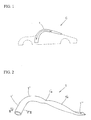
- Figure 1 is a diagram illustrating a position where an A-pillar to which a fiber reinforced resin member according to the present invention is applied is mounted in a vehicle.
- Figure 2 is a perspective view of an embodiment of the manufactured fiber reinforced resin member.
- Figure 3 is a sectional view of the fiber reinforced resin member taken along line III-III in Figure 2 .
- Figure 4 is a perspective view of an embodiment of a manufacturing apparatus according to the present invention.
- Figure 5 is a side view of the manufacturing apparatus according to the present invention.
- Figure 6 is a diagram illustrating a winding aspect of longitudinal yarns formed all along the length of the mandrel.
- Figure 7 is a diagram illustrating a winding aspect of longitudinal yarns and diagonal yarns at a bent portion of the mandrel.
- Figure 8 is a diagram illustrating the inclination of the longitudinal yarns to a longitudinal direction of the fiber reinforced resin member.
- the shape of the mandrel and the number of winding layers forming the fiber reinforced resin member are not limited to those shown in the embodiments.
- the fiber reinforced resin member according to the present invention is suitable for A-pillars of a vehicle, which needs to exhibit an appropriate flexural strength and appropriate impact resistance performance.
- the A-pillars are support members for a front window which are positioned in front of and on the right and left side of a passenger in a vehicle C shown in Figure 1 . Applying the fiber reinforced resin member 1 to the A-pillars allows the above-described strength characteristics to be sufficiently offered.
- the fiber reinforced resin member also has a light weight. Thus, the fiber reinforced resin member is particularly suitable for recent hybrid vehicles and the like.
- Figure 2 shows an embodiment of the fiber reinforced resin member 1 applied to the A-pillars.
- the fiber reinforced resin member 1 is not a simple, linear cylindrical member. Since the fiber reinforced resin member 1 is applied to the A-pillars, the fiber reinforced resin member 1 is shaped to have not only straight portions 1' and 1'a but also a bent portion 1".
- the fiber reinforced resin member 1 further has a plate portion 1"' that allows the fiber reinforced resin member 1 to be fastened to another member making up the vehicle. Furthermore, the sectional shapes of relevant portions are not uniform.
- the straight portion 1' has a circular cross section, and the straight portion 1'a has an elliptic cross section.
- the bent portion 1" has an elliptic cross section with a partly inwardly recessed portion 1"a.
- the fastening plate portion 1"' has a flat cross section as well as a bolt hole.
- FIG 3 is a sectional view of the fiber reinforced resin member 1 illustrating the configuration thereof.
- the fiber reinforced resin member 1 is composed of a mandrel 1a which is a core material made of an ABS resin, a winding layer 1b wound around the outer periphery of the mandrel 1a and made up of longitudinal yarns, a winding layer 1c wound around the outer periphery of the winding layer 1b and made up of diagonal yarns, a winding layer 1d made up of longitudinal yarns located around the outer periphery of the winding layer 1c, and a winding layer 1e made up of diagonal yarns located around the outer periphery of the winding layer 1d.
- the winding layers are impregnated with a thermosetting resin, which is then hardened to form the fiber reinforced resin member 1.
- the numbers of the winding layers made up of the longitudinal yarns and the winding layers made up of the diagonal yarns are not limited to those shown in the figures but may be at least three.
- a manufacturing apparatus which, in manufacturing the fiber reinforced resin member 1, manufactures an intermediate member (a member in which the winding layers formed around the outer periphery of the mandrel), which has not been impregnated with the resin yet, as well as an operation aspect of the manufacturing apparatus 100.
- Figure 4 is a perspective view generally illustrating the manufacturing apparatus 100.
- Figure 5 is a side view illustrating the manufacturing apparatus.
- the manufacturing apparatus 100 has two braiders, a first braider 10 and a second braider 20 both of which are annular and have a central opening through which the mandrel 1a can reciprocate.
- the braiders 10 and 20 are arranged at a predetermined distance from each other. Wheels 15, 15 and 22, 22 are attached to legs of the braiders 10 and 20, respectively. An elongate moving rail 30 is installed between the wheels 15, 15 and between the wheels 22, 22. Positioning members 40, 40 extend vertically from opposite ends of the moving rail 30. The mandrel 1a is fixedly positioned at upper ends of the positioning members 40, 40.
- the braiders 10 and 20 are arranged so as to be able to be moved, by a servo motor or a cylinder mechanism (not shown in the drawings), within planes (which are substantially orthogonal to arrows X1 and X2) defined by the annular portions thereof, in a posture in which the predetermined distance is maintained between the braiders 10 and 20.
- the servo motor or cylinder mechanism moves the braiders 10 and 20 so as to prevent the mandrel 1a from interfering with the annular portions, that is, so that the mandrel 1a can pass through the substantial center of the central opening of each of the annular portions.
- the wheels 15, 15 and wheels 22, 22 may be configured so that the distance between the pair of wheels 15, 15 (22, 22) and the braider 10 (20) can follow the rail 30 even though the braider 10 (20) is moved by the servo motor or cylinder mechanism.
- the moving rail 30, on which the mandrel 1a is fixedly positioned can be moved in the directions of arrows X1 and X2 by rotational driving of at least one of the pair of wheels 15, 15 and the pair of wheels 22, 22 or by moving means (not shown in the drawings). If the mandrel 1a is shaped so as to not to interfere with the annular portions, the servo motor or cylinder mechanism may be omitted.
- a large number of gears are contained in the first braider 10 and arranged in a circumferential direction thereof.
- Gear rotating shafts 11, of the gears are shown in the figure.
- a bobbin moving groove 12 is formed in the first braider 10 so as to meander in a shape of the number eight in order to bypass the gear rotating shafts.
- Bobbins 13, for diagonal yarns move along the moving groove 12 to supply diagonal yarns P, to the outer periphery of the mandrel.
- a guide ring 14 is located, by support means (not shown in the drawings), on a side of each of the first braiders 10, 20 which corresponds to the direction of arrow X1 (the guide ring 14 located on a side of the braider 20 which corresponds to the direction of arrow X1 is shown only in Figure 5 ).
- the diagonal yarns P, extending from the first bobbins 13, and longitudinal yarns Q, extending from second bobbins 21, are guided to the guide ring 14 and thus supplied to the outer periphery of the mandrel.
- the computer contains a control section that controls the moving speed of the bobbins 13, in the braider 10, the rotation speed of the braider 20, and the moving speed of the mandrel 1a, which relates to the moving speed of the bobbins 13, in the braider 10 and the rotation speed of the braider 20.
- the mandrel 1a is moved to a right end in Figures 4 and 5 , and from this position, moved leftward (the direction X1). Before the movement of the mandrel 1a, ends of the diagonal yarns P and longitudinal yarns Q are taped to the outer periphery of the mandrel.
- the braider 10 is rotated, with the braider 20 not rotated, and the mandrel 1a is moved. That is, around the outer periphery of the mandrel 1a, the longitudinal yarns Q, are laid out in the longitudinal direction of the mandrel 1a, and the diagonal yarns P, are laid out on the longitudinal yarns Q,
- the braider 20 starts to be rotated slowly. In the meantime, the braider 10 is continuously rotating.
- the rotation speed (or rotation number) of the braider 20 is adjusted according to the moving speed of the mandrel 1a.
- the rotation speed of the braider 20 is set at least to such a value as allows the longitudinal yarns Q to be spirally wound around the outer periphery of the mandrel 1a at an angle of 10 to 15 degrees to the longitudinal direction.
- the above-described control section adjusts the rotation speed of the braider 20 and the moving speed of the mandrel 1a.
- the winding of the longitudinal yarns progresses. Once the mandrel 1a reaches the straight portion 1'a, the rotation of the braider 20 is stopped. Then, the longitudinal yarns Q, are laid out in the longitudinal direction of the mandrel 1a. The diagonal yarns P, are laid out on the longitudinal yarns Q,
- Figure 6 schematically shows the winding aspect of the longitudinal yarns formed around the outer periphery of the mandrel.
- the longitudinal yarns are laid out along the longitudinal direction.
- the spirally wound longitudinal yarns are laid out.
- the rotation of the braider refers to movement of the bobbin 13, in the first braider 10 along the bobbin moving groove 12, as shown in the braider 10 in Figure 4 .
- Each of the bobbins 13, moves meanderingly and timely so that a clockwise (a direction Y1 in Figure 4 ) set of bobbins and a counterclockwise (a direction Y2 in Figure 4 ) set of bobbins avoid interfering with each other.
- the plurality of bobbins 13, move at a predetermined moving speed in synchronism with the movement of the mandrel 1a to wind the diagonal yarns P, at an angle of 45 degrees to the longitudinal direction of the mandrel 1a.
- the braider 20 has the same structure but rotates at the bent portion of the mandrel 1a.
- Figure 7 shows a winding form of the longitudinal yarns Q in the bent portion of the mandrel and a winding form of the diagonal yarns P formed around the outer periphery of the longitudinal yarns Q.
- the diagonal yarns P are wound around the outer periphery of the spirally wound longitudinal yarns Q or a plurality of such combinations are provided, to form a winding aspect in which the longitudinal yarns and the diagonal yarns are braided.
- the above-described intermediate member is transferred to a mold with a cavity space in a predetermined form.
- the intermediate member is impregnated with the thermosetting resin, which is then hardened.
- a resin impregnation and hardening method a well-known RTM method may be applied which places, in the mold, the intermediate member with the winding layers formed around the outer periphery of the mandrel, then places the cavity in a vacuum atmosphere, then fills the resin into the cavity placed in a vacuum atmosphere, and pressurizes and molds the intermediate member.
- Table 1 clearly indicates that the flexural rigidity of the fiber reinforced resin member is maximized when the longitudinal yarns are at an angle of 0 degree and the elasticity modulus decreases sharply when the angle is larger than 15 degrees.
- the angle at which the longitudinal yarns are spirally wound at the bent portion of the mandrel is preferably set within the range of 10 to 15 degrees to the longitudinal direction of the fiber reinforced resin member.
Description
- The present invention relates to a fiber reinforced resin member used particularly as roof side rails of a vehicle, and a method of manufacturing the fiber reinforced resin member, and an apparatus manufacturing a fiber fabric for the fiber reinforced resin member.
- A-pillars (also called roof side rails; pillars positioned obliquely forward of a driver and at laterally opposite ends of the vehicle to support a front window) need to offer both a static strength characteristic (for example, flexural rigidity) and a crash resistance characteristic exhibited at the time of a collision of the vehicle. For recent hybrid vehicles, electric vehicles, and the like for which efforts have been made to improve the safety of the vehicle and to reduce the weight thereof, a fiber reinforced resin member, which has an appropriate rigidity and a light weight, is suitable as the A-pillars.
- An example of the fiber reinforced resin member is a carbon fiber reinforced plastic member (CFRP). The fiber reinforced resin member is formed by using fiber yarns with a predetermined tensile strength and the like as a longitudinal yarn extending in a longitudinal direction of the member and a diagonal yarn with a predetermined inclination to the longitudinal direction, to braid both the longitudinal yarn and the diagonal yarn to form a multiple winding layer structure, then impregnating the multiple winding layer structure with resin, and hardening the resin. In the fiber reinforced resin member, the longitudinal yarn contributes to the flexural rigidity. The winding layer structure including the winding layers with the different orientations contributes to the crash resistance characteristic.
- The above-described roof side rails are shaped along the front side of the vehicle so as to extend to a roof thereof, that is, shaped such that a straight portion and a bent portion are continuous with each other. The longitudinal yarn and the diagonal yarn are wound along this shape.
-
Patent Document 1 describes a method for manufacturing a fiber fabric forming the above-described fiber reinforced resin member. Specifically, a manufacturing apparatus is used which has two braiders in each of which an axial (longitudinal) yarn supply section and a braider yarn supply section are installed. Both an axial (longitudinal) yarn and a braider yarn are wound around the outer periphery of a linear mandrel by carrying out a control method of reciprocating the linear mandrel through the braiders and stopping driving of one of the braiders while the other braider is being driven. Patent Document 1:JP Patent No. 3215308 EP 0523471 A1 disclose a method of manufacturing fibre reinforced products in which a prefabricated supporting core is drawn, together with the unidirectional fibres and the braided fibres emerging from a braiding machine, through a thread eyelet, the braided fibres which come to lie at least partly on the outside pressing the unidirectional fibres onto the supporting core.
DE 4004473 A1 discloses a method for the production of composite components where one or more layers of unidirectional fibres are combined with a braided fibre structure on a shaped core. Both sets of fibres are drawn through an eye and the outer braiding fibres press the inner unidirectional fibres onto the core. The unidirectional fibres may be located between the core and the braiding fibres or are interwoven between the contra-rotating braiding fibres - The apparatus disclosed in
Patent Document 1 can wind both the longitudinal yarn and the braider yarn around the outer periphery of the linear mandrel. However, if the longitudinal yarn is supplied to the outer periphery of the mandrel including a bent portion as is the case with the roof side rails, then at the bent portion, the longitudinal yarn may slip on the mandrel and fail to be evenly laid out around the outer periphery of the mandrel. If the longitudinal yarn slips at the bent portion, braiding density may vary depending on an area of the mandrel; the longitudinal yarn may concentrate in some areas and may be absent in other areas. Thus, naturally, the bent portion offers a low strength. - The present invention has been made in view of these problems. An object of the present invention is to provide a high-quality fiber reinforced resin member that enables the longitudinal yarn to be laid out, without slipping, around the outer periphery of the mandrel having at least the bent portion, thus allowing the longitudinal yarn and the diagonal yarn to be evenly laid out, and a method of manufacturing the fiber reinforced resin member, as well as an apparatus manufacturing a fiber fabric for the fiber reinforced resin member.
- To accomplish the object, the fiber reinforced resin member according to the present invention including an elongate fiber fabric formed by braiding a plurality of longitudinal yarns extending in a longitudinal direction of the fiber fabric and a plurality of diagonal yarns inclined at a predetermined angle to the longitudinal direction, the fiber fabric being impregnated with resin that is then hardened, the fiber reinforced resin member being characterized in that the fiber reinforced resin member has at least a bent portion, and the longitudinal yarns are spirally wound at the bent portion, in a posture in which the longitudinal yarns are inclined at the predetermined angle to the longitudinal direction.
- The fiber reinforced resin member is formed by, for example, alternately forming, around an outer periphery of the mandrel, serving as a core material for the fiber reinforced resin member, a winding layer made up of the longitudinal yarns extending in the longitudinal direction of the mandrel and a winding layer made up of the diagonal yarns (braider yarns) inclined at the predetermined angle to the longitudinal direction to form a plurality of sets each of a combination of the two types of winding layers, filling a thermosetting resin between the winding layers, and hardening the resin.
- The mandrel used is made of any material such as steel or rein. Depending on the shape of the fiber reinforced resin member, the mandrel finally remains in the fiber reinforced resin member as a member component without being pulled out. If the fiber reinforced resin member is applied as the already described A-pillar, since the A-pillar is not a simple elongate cylindrical member but has a complicated shape, for example, an eclipse having one end with a circular cross section, a recessed center, and the other end gradually approaching a bolt fastening plate, the mandrel, serving as a core material, remains as a member component. In this case, to minimize the weight of the fiber reinforced resin member as a whole, the mandrel is preferably molded using an ABS resin (a copolymerized synthetic resin of acrylonitrile, butadiene, and styrene), which has a light weight and a high strength.
- The fiber reinforced resin member according to the present invention is characterized by having at least a bent portion in which the wound longitudinal yarns are evenly laid out, and to achieve the even layout, the longitudinal yarns are spirally wound at the bent portion so as to incline at the predetermined angle to the longitudinal direction of the fiber reinforced resin member.
- Heuristics and experiments of the present inventor and the like indicate that an attempt to lay out the longitudinal yarns so that the longitudinal yarns extend in the longitudinal direction in the bent portion of the fiber reinforced resin member results in slippage of the longitudinal yarns on the outer periphery of the mandrel. This in turn indicates that manufacturing a fiber reinforced resin member with an even layout of the longitudinal yarns (the longitudinal yarns with a uniform density) is extremely difficult.
- Thus, in the fiber reinforced resin member according to the present invention, the longitudinal yarns are spirally wound at the bent portion at the predetermined angle to the longitudinal direction of the fiber reinforced resin member. The preferable range of the angle is specified to be 10 to 15 degrees.
- The experiments of the present inventor and the like indicate that when the angle of the longitudinal yarns at the bent portion is smaller than 10 degrees, the longitudinal yarns slip on the mandrel and that when the angle exceeds 15 degrees, the flexural rigidity of the fiber reinforced resin member decreases significantly. The above-described angle range is thus specified with both the processibility and strength of the fiber reinforced resin member taken into account. Of course, the longitudinal yarns in the straight portion of the fiber reinforced resin member are laid out in a posture in which the longitudinal yarns are oriented in the longitudinal direction of the fiber reinforced resin member. Furthermore, the angle of the diagonal yarns to the longitudinal direction of the fiber reinforced resin member is set to about 45 degrees.
- In connection with the strength characteristic of the fiber reinforced resin member, the flexural rigidity (flexural strength) thereof depends significantly on a hardened resin layer made up of the winding layer of the longitudinal yarns. The crash resistance (impact resistance) performance of the fiber reinforced resin member depends significantly on a braiding structure of the diagonal yarns and the longitudinal yarns.
- The fiber reinforced resin member is formed by forming a plurality of (for example, four) sets each of the combination of the winding layer of the longitudinal yarns and the winding layer of the diagonal yarns on the outer periphery of the mandrel, then impregnating the fiber winding layers with the thermosetting resin, and hardening the thermosetting resin.
- According to the fiber reinforced resin member according to the present invention, even if the fiber reinforced resin member has the bent portion, a possible disadvantageous situation is prevented in which the longitudinal yarns may slip on the outer periphery of the mandrel to form an uneven winding layer of the longitudinal yarns. Furthermore, in winding the longitudinal yarns at the bent portion, the rotation speed of a braider having a longitudinal yarn supply section and the movement speed of the mandrel have only to be adjusted so that the longitudinal yarns are spirally wound around the outer periphery of the bent portion of the mandrel at an angle of about 10 to 15 degrees. This prevents the processing efficiency of the fiber reinforced resin member from being reduced by processing of the bent portion.
- Furthermore, the present invention provides a method of manufacturing a fiber reinforced resin member, the method being characterized by comprising a first step of supplying a mandrel having at least a bent portion, with a longitudinal yarn extending in a longitudinal direction of the mandrel and a diagonal yarn inclined at a predetermined angle to the longitudinal direction, to braid a plurality of the longitudinal yarns and a plurality of the diagonal yarns to manufacture an elongate fiber fabric, and a second step of impregnating the fiber fabric with resin and hardening the resin to manufacture the fiber reinforced resin member, and in that in the first step, the longitudinal yarns are spirally wound at a bent portion of the mandrel in a posture in which the longitudinal yarns are inclined at a predetermined angle to the longitudinal direction.
- The manufacturing method according to the present invention forms, by braiding, a plurality of layers made up of the longitudinal yarns and a plurality of layers made up of the diagonal yarns, around the outer periphery of the mandrel having the bent portion as described above, then impregnates the layers with the thermosetting resin and hardens the thermosetting resin. To be evenly laid out at the bent portion, the longitudinal yarns are spirally wound at the bent portion at the predetermined angle to the longitudinal direction of the fiber reinforced resin member.
- The angle of the spiral winding is adjusted within the range of 10 to 15 degrees to the longitudinal direction of the fiber reinforced resin member as already described.
- A predetermined number of combinations of a winding layer of the longitudinal yarns and a winding layer of the diagonal yarns are formed around the outer periphery of the mandrel to form an intermediate member. The intermediate member is transferred to a mold with a predetermined cavity space. A thermosetting resin is filled into the mold and then hardened.
- As a resin impregnation and hardening method, a well-known RTM method may be applied which places the intermediate member with the winding layers formed around the outer periphery of the mandrel, in the mold, then places the cavity in a vacuum atmosphere, then fills the resin into the cavity, and pressurizes and molds the intermediate member. A measure may be taken which, before vacuum suction of the interior of the cavity, places a balloon or a large number of beads inside the mandrel to exert an internal pressure on the mandrel. Instead of filling the resin into the cavity, another method pre-winds a film of a thermosetting resin around the outer periphery of the mandrel so that a thermal treatment allows the film to be melted to impregnate the fiber fabric with the melted thermosetting resin.
- Moreover, an apparatus manufacturing a fiber fabric according to the present invention manufactures an elongate fiber fabric by braiding a plurality of longitudinal yarns extending in a longitudinal direction of the fiber fabric and a plurality of diagonal yarns inclined at a predetermined angle to the longitudinal direction, and comprises a first braider and a second braider installed at a distance from each other, a plurality of first bobbins installed in the first braider to supply the diagonal yarns and a plurality of second bobbins installed in the second braider to supply the longitudinal yarns, moving means for moving the mandrel having at least a bent portion, inside the first and second braiders in a direction from the second braider toward the first braider, and control means that rotates both the first and second braiders at the bent portion of the mandrel.
- Unlike in the case of the configuration of a conventional braider machine, the manufacturing apparatus according to the present invention is roughly composed of a braider (second braider) having a second bobbins from which the longitudinal yarns are fed and a braider (first braider) which is positioned in front of the second braider and having a first bobbins from which the diagonal yarns are fed.
- For example, a winding layer of the longitudinal yarns and a winding layer of the diagonal yarns are formed as follows. Ends of the longitudinal and diagonal yarns are wound around (or taped to) an end of the mandrel. The mandrel is moved with the first braider rotated and the second braider not rotated. Thus, the winding layer of the longitudinal yarns is formed and the winding layer of the diagonal yarns is simultaneously formed on the winding layer of the longitudinal yarns. The longitudinal yarns are laid out and fixed on the mandrel by the winding layer of the diagonal yarns.
- To form the winding layers at the bent portion of the mandrel, the mandrel is moved with the second braider slowly rotated. At this time, the rotation speed of the second braider is determined by the moving speed of the mandrel and the peripheral length of the bent portion so that the longitudinal yarns are spirally wound at an inclination of 10 to 15 degrees.
- When the formation of the winding layer in the section of the bent portion of the mandrel is finished and the process enters the straight portion again, the rotation of the second braider is stopped, with the mandrel continuing to be moved. Then, the longitudinal yarns are laid out at the straight portion in the longitudinal direction, and the winding layer of the diagonal yarns formed by the fist braider is simultaneously formed on the longitudinal yarns.
- Here, in connection with the formation of the winding layer of the diagonal yarns, the rotation of the first and second braiders is based on a large number of gears built in the braiders in associated postures in a ring direction and a bobbin moving groove which is formed in the ring direction so as to bypass rotating shafts of the gears; the rotation of the first and second braiders refers to rotation of the gears moving the bobbin through the moving groove to supply the diagonal yarns, thus winding the diagonal yarns around the outer periphery of the mandrel passing through the braider.
- Furthermore, the manufacturing apparatus includes moving means for fixedly positioning the mandrel and moving the mandrel as described above, and control means for controllably rotationally driving one or both of the braiders at a rotation speed corresponding to the moving speed of the mandrel every time the longitudinal yarn or the diagonal yarn is formed on the mandrel.
- The above-described manufacturing apparatus according to the present invention allows predetermined numbers of winding layers of the longitudinal yarns and winding layers of the diagonal yarns to be simultaneously formed around the outer periphery of the mandrel. In particular, the use of the manufacturing apparatus configured as described above allows the winding layer of the longitudinal yarns to be efficiently formed without causing the longitudinal yarns to slip at the bent portion of the mandrel.
- The intermediate member manufactured by the manufacturing apparatus is transferred to the mold as already described. The process then shifts to the resin impregnation and hardening step.
- As appreciated from the above description, with the method of manufacturing the fiber reinforced resin member and the apparatus manufacturing the fiber fabric according to the present invention, the longitudinal yarns can be laid out, without slipping, around the outer periphery of the mandrel having the bent portion, and the winding layer of the longitudinal yarns having an even density can be efficiently formed. Furthermore, with the fiber reinforced resin member according to the present invention, even if the fiber reinforced resin member has a bent portion, the longitudinal yarns are evenly laid out at the bent portion. The longitudinal yarns are thus wound at a uniform density, providing a fiber reinforced resin member generally exhibiting an excellent flexural rigidity characteristic.
-
-
Figure 1 is a diagram illustrating a position where an A-pillar to which a fiber reinforced resin member according to the present invention is applied is mounted in a vehicle. -
Figure 2 is a perspective view of an embodiment of the manufactured fiber reinforced resin member. -
Figure 3 is a sectional view of the fiber reinforced resin member taken along line III-III inFigure 2 . -
Figure 4 is a perspective view of an embodiment of a manufacturing apparatus according to the present invention. -
Figure 5 is a side view of the manufacturing apparatus according to the present invention. -
Figure 6 is a diagram illustrating a winding aspect of longitudinal yarns formed all along the length of the mandrel. -
Figure 7 is a diagram illustrating a winding aspect of longitudinal yarns and diagonal yarns at a bent portion of the mandrel. -
Figure 8 is a diagram illustrating the inclination of the longitudinal yarns to a longitudinal direction of the fiber reinforced resin member. - 1 Fiber reinforced resin member, 1a Mandrel, 1b, 1d Winding layers of longitudinal yarns, 1c, 1e Winding layer of diagonal layers, 1', 1a' Straight portions, 1" Bent portion, 1"' Fastening plate portion, 10 First braider, 11 Gear rotating shaft, 12 Bobbin moving groove, 13 First bobbin, 14 Guide ring, 15 Wheel, 20 Second braider, 21 Second bobbin, 22 Wheel, 30 Moving rail, 40 Positioning member, 100 Manufacturing apparatus (braider machine), P Diagonal yarn, Q Longitudinal yarn
- Embodiments of the present invention will be described below with reference to the drawings.
Figure 1 is a diagram illustrating a position where an A-pillar to which a fiber reinforced resin member according to the present invention is applied is mounted in a vehicle.Figure 2 is a perspective view of an embodiment of the manufactured fiber reinforced resin member.Figure 3 is a sectional view of the fiber reinforced resin member taken along line III-III inFigure 2 .Figure 4 is a perspective view of an embodiment of a manufacturing apparatus according to the present invention.Figure 5 is a side view of the manufacturing apparatus according to the present invention.Figure 6 is a diagram illustrating a winding aspect of longitudinal yarns formed all along the length of the mandrel.Figure 7 is a diagram illustrating a winding aspect of longitudinal yarns and diagonal yarns at a bent portion of the mandrel.Figure 8 is a diagram illustrating the inclination of the longitudinal yarns to a longitudinal direction of the fiber reinforced resin member. The shape of the mandrel and the number of winding layers forming the fiber reinforced resin member are not limited to those shown in the embodiments. - The fiber reinforced resin member according to the present invention is suitable for A-pillars of a vehicle, which needs to exhibit an appropriate flexural strength and appropriate impact resistance performance. The A-pillars are support members for a front window which are positioned in front of and on the right and left side of a passenger in a vehicle C shown in
Figure 1 . Applying the fiber reinforcedresin member 1 to the A-pillars allows the above-described strength characteristics to be sufficiently offered. The fiber reinforced resin member also has a light weight. Thus, the fiber reinforced resin member is particularly suitable for recent hybrid vehicles and the like. -
Figure 2 shows an embodiment of the fiber reinforcedresin member 1 applied to the A-pillars. The fiber reinforcedresin member 1 is not a simple, linear cylindrical member. Since the fiber reinforcedresin member 1 is applied to the A-pillars, the fiber reinforcedresin member 1 is shaped to have not only straight portions 1' and 1'a but also abent portion 1". The fiber reinforcedresin member 1 further has aplate portion 1"' that allows the fiber reinforcedresin member 1 to be fastened to another member making up the vehicle. Furthermore, the sectional shapes of relevant portions are not uniform. The straight portion 1' has a circular cross section, and the straight portion 1'a has an elliptic cross section. Thebent portion 1" has an elliptic cross section with a partly inwardly recessedportion 1"a. Thefastening plate portion 1"' has a flat cross section as well as a bolt hole. -
Figure 3 is a sectional view of the fiber reinforcedresin member 1 illustrating the configuration thereof. The fiber reinforcedresin member 1 is composed of amandrel 1a which is a core material made of an ABS resin, a winding layer 1b wound around the outer periphery of themandrel 1a and made up of longitudinal yarns, a windinglayer 1c wound around the outer periphery of the winding layer 1b and made up of diagonal yarns, a windinglayer 1d made up of longitudinal yarns located around the outer periphery of the windinglayer 1c, and a windinglayer 1e made up of diagonal yarns located around the outer periphery of the windinglayer 1d. The winding layers are impregnated with a thermosetting resin, which is then hardened to form the fiber reinforcedresin member 1. The numbers of the winding layers made up of the longitudinal yarns and the winding layers made up of the diagonal yarns are not limited to those shown in the figures but may be at least three. - Description will be given below of a manufacturing apparatus (braider machine) 100 which, in manufacturing the fiber reinforced
resin member 1, manufactures an intermediate member (a member in which the winding layers formed around the outer periphery of the mandrel), which has not been impregnated with the resin yet, as well as an operation aspect of themanufacturing apparatus 100. -
Figure 4 is a perspective view generally illustrating themanufacturing apparatus 100.Figure 5 is a side view illustrating the manufacturing apparatus. - The
manufacturing apparatus 100 has two braiders, afirst braider 10 and asecond braider 20 both of which are annular and have a central opening through which themandrel 1a can reciprocate. - The
braiders Wheels braiders rail 30 is installed between thewheels wheels Positioning members rail 30. Themandrel 1a is fixedly positioned at upper ends of thepositioning members - In the illustrated posture, the
braiders braiders braiders mandrel 1a from interfering with the annular portions, that is, so that themandrel 1a can pass through the substantial center of the central opening of each of the annular portions. Here, thewheels wheels wheels 15, 15 (22, 22) and the braider 10 (20) can follow therail 30 even though the braider 10 (20) is moved by the servo motor or cylinder mechanism. Furthermore, the movingrail 30, on which themandrel 1a is fixedly positioned, can be moved in the directions of arrows X1 and X2 by rotational driving of at least one of the pair ofwheels wheels mandrel 1a is shaped so as to not to interfere with the annular portions, the servo motor or cylinder mechanism may be omitted. - A large number of gears are contained in the
first braider 10 and arranged in a circumferential direction thereof. Gear rotatingshafts 11, of the gears are shown in the figure. Moreover, abobbin moving groove 12 is formed in thefirst braider 10 so as to meander in a shape of the number eight in order to bypass the gear rotating shafts.Bobbins 13, for diagonal yarns move along the movinggroove 12 to supply diagonal yarns P, to the outer periphery of the mandrel. - Furthermore, a
guide ring 14 is located, by support means (not shown in the drawings), on a side of each of thefirst braiders guide ring 14 located on a side of thebraider 20 which corresponds to the direction of arrow X1 is shown only inFigure 5 ). The diagonal yarns P, extending from thefirst bobbins 13, and longitudinal yarns Q, extending fromsecond bobbins 21, are guided to theguide ring 14 and thus supplied to the outer periphery of the mandrel. - Various instruction signals from a computer (not shown in the drawings) are transmitted to the illustrated
manufacturing apparatus 100 by wired or wireless communication. The computer contains a control section that controls the moving speed of thebobbins 13, in thebraider 10, the rotation speed of thebraider 20, and the moving speed of themandrel 1a, which relates to the moving speed of thebobbins 13, in thebraider 10 and the rotation speed of thebraider 20. - First, to simultaneously form winding layers made up of the diagonal yarns P, and the longitudinal yarns Q, around the outer periphery of the
mandrel 1a, themandrel 1a is moved to a right end inFigures 4 and5 , and from this position, moved leftward (the direction X1). Before the movement of themandrel 1a, ends of the diagonal yarns P and longitudinal yarns Q are taped to the outer periphery of the mandrel. - To form the winding layers at the straight portion of the
mandrel 1a, only thebraider 10 is rotated, with thebraider 20 not rotated, and themandrel 1a is moved. That is, around the outer periphery of themandrel 1a, the longitudinal yarns Q, are laid out in the longitudinal direction of themandrel 1a, and the diagonal yarns P, are laid out on the longitudinal yarns Q, - Once the
mandrel 1a reaches a predetermined position in front of thebraider 10, thebraider 20 starts to be rotated slowly. In the meantime, thebraider 10 is continuously rotating. - The rotation speed (or rotation number) of the
braider 20 is adjusted according to the moving speed of themandrel 1a. The rotation speed of thebraider 20 is set at least to such a value as allows the longitudinal yarns Q to be spirally wound around the outer periphery of themandrel 1a at an angle of 10 to 15 degrees to the longitudinal direction. The above-described control section adjusts the rotation speed of thebraider 20 and the moving speed of themandrel 1a. - The winding of the longitudinal yarns progresses. Once the
mandrel 1a reaches the straight portion 1'a, the rotation of thebraider 20 is stopped. Then, the longitudinal yarns Q, are laid out in the longitudinal direction of themandrel 1a. The diagonal yarns P, are laid out on the longitudinal yarns Q, - The above-described series of control allows the longitudinal yarns Q, to be evenly wound around the outer periphery of the
mandrel 1a and then allows the diagonal yarns P, to be evenly wound on the longitudinal yarns Q,Figure 6 schematically shows the winding aspect of the longitudinal yarns formed around the outer periphery of the mandrel. In the straight portion, the longitudinal yarns are laid out along the longitudinal direction. In the bent portion, the spirally wound longitudinal yarns are laid out. - Here, the rotation of the braider refers to movement of the
bobbin 13, in thefirst braider 10 along thebobbin moving groove 12, as shown in thebraider 10 inFigure 4 . Each of thebobbins 13, moves meanderingly and timely so that a clockwise (a direction Y1 inFigure 4 ) set of bobbins and a counterclockwise (a direction Y2 inFigure 4 ) set of bobbins avoid interfering with each other. The plurality ofbobbins 13, move at a predetermined moving speed in synchronism with the movement of themandrel 1a to wind the diagonal yarns P, at an angle of 45 degrees to the longitudinal direction of themandrel 1a. Thebraider 20 has the same structure but rotates at the bent portion of themandrel 1a. -
Figure 7 shows a winding form of the longitudinal yarns Q in the bent portion of the mandrel and a winding form of the diagonal yarns P formed around the outer periphery of the longitudinal yarns Q. The diagonal yarns P are wound around the outer periphery of the spirally wound longitudinal yarns Q or a plurality of such combinations are provided, to form a winding aspect in which the longitudinal yarns and the diagonal yarns are braided. - The above-described intermediate member is transferred to a mold with a cavity space in a predetermined form. In the mold, the intermediate member is impregnated with the thermosetting resin, which is then hardened. As a resin impregnation and hardening method, a well-known RTM method may be applied which places, in the mold, the intermediate member with the winding layers formed around the outer periphery of the mandrel, then places the cavity in a vacuum atmosphere, then fills the resin into the cavity placed in a vacuum atmosphere, and pressurizes and molds the intermediate member.
- Discussion of the angle of the longitudinal yarns to the longitudinal direction of the fiber reinforced resin member and the elasticity modulus of the fiber reinforced resin member as a bending member.
The present inventor and the like examined a relationship between the angle (θ) of the longitudinal yarns to the longitudinal direction of the fiber reinforced resin member and the elasticity modulus of the fiber reinforced resin member as a bending member. The results of the examination are shown in Table 1, shown below. The angle (θ) of the longitudinal yarns to the longitudinal direction of the fiber reinforced resin member is shown inFigure 8 .[Table 1] θ (°) 0 10 15 20 30 45 E (GPa) 150 120 100 70 28 22 - Table 1 clearly indicates that the flexural rigidity of the fiber reinforced resin member is maximized when the longitudinal yarns are at an angle of 0 degree and the elasticity modulus decreases sharply when the angle is larger than 15 degrees.
- On the other hand, processibility was checked with the angle varied at which the longitudinal yarns were spirally wound at the bent portion of the mandrel. The results of the check indicate that an angle θ of smaller than 10 degrees causes the longitudinal yarns to slip on the outer periphery of the mandrel, sharply reducing processibility.
- Thus, in connection with the flexural rigidity and processibility of the fiber reinforced resin member, the conclusion can be drawn that the angle at which the longitudinal yarns are spirally wound at the bent portion of the mandrel is preferably set within the range of 10 to 15 degrees to the longitudinal direction of the fiber reinforced resin member.
Claims (6)
- A fiber reinforced resin member (1) including an elongate fiber fabric formed from a plurality of longitudinal yarns extending in a longitudinal direction of the fiber fabric (Q) and a plurality of diagonal yarns inclined at a predetermined angle to the longitudinal direction (P) the fiber fabric braided together and then impregnated with resin that is then hardened, the fiber reinforced resin member being characterized:in that the fiber reinforced resin member has at least a bent portion (1"), andthe longitudinal yarns are spirally wound at the bent portion, in a posture in which the longitudinal yarns are inclined at the predetermined angle to the longitudinal direction.
- The fiber reinforced resin member according to Claim 1, wherein inclination of the longitudinal yarns to the longitudinal direction is within a range of 10 to 15 degrees.
- A method of manufacturing a fiber reinforced resin member, the method being characterized by comprising a first step of supplying a mandrel (1a) having at least a bent portion, with a plurality of longitudinal yarns extending in a longitudinal direction of the mandrel and a plurality of diagonal yarns inclined at a predetermined angle to the longitudinal direction, to braid a plurality of the longitudinal yarns and a plurality of the diagonal yarns to manufacture an elongate fiber fabric, and a second step of impregnating the fiber fabric with resin and hardening the resin to manufacture the fiber reinforced resin member, and
in that in the first step, the longitudinal yarns are spirally wound at a bent portion of the mandrel in a posture in which the longitudinal yarns are inclined at a predetermined angle to the longitudinal direction. - The method of manufacturing the fiber reinforced resin member according to Claim 3, wherein inclination of the longitudinal yarns to the longitudinal direction is within a range of 10 to 15 degrees.
- An apparatus (100) for manufacturing a fiber fabric, the apparatus manufacturing an elongate fiber fabric by braiding a plurality of longitudinal yarns extending in a longitudinal direction of the fiber fabric and a plurality of diagonal yarns inclined at a predetermined angle to the longitudinal direction, the apparatus comprising:a first braider (10) and a second braider (20) installed at a distance from each other;a plurality of first bobbins (13) installed in the first braider to supply the diagonal yarns, and a plurality of second bobbins (21) installed in the second braider to supply the longitudinal yarns;moving means for moving the mandrel having at least a bent portion, inside the first and second braiders in a direction from the second braider toward the first braider; andcontrol means that rotates both the first and second braiders at the bent portion of the mandrel.
- An apparatus manufacturing a fiber fabric according to claim 5, wherein the control means further rotates only the first braider at a straight portion of the mandrel.
Applications Claiming Priority (2)
| Application Number | Priority Date | Filing Date | Title |
|---|---|---|---|
| JP2007209901A JP4263752B2 (en) | 2007-08-10 | 2007-08-10 | FIBER-REINFORCED RESIN MEMBER, ITS MANUFACTURING METHOD, AND FIBER FABRIC PRODUCTION DEVICE |
| PCT/JP2008/064288 WO2009022641A1 (en) | 2007-08-10 | 2008-08-08 | Fiber-reinforced resin member, process for producing the same, and apparatus for producing woven fiber fabric |
Publications (4)
| Publication Number | Publication Date |
|---|---|
| EP2189273A1 EP2189273A1 (en) | 2010-05-26 |
| EP2189273A4 EP2189273A4 (en) | 2010-12-15 |
| EP2189273B1 true EP2189273B1 (en) | 2012-09-19 |
| EP2189273B8 EP2189273B8 (en) | 2013-01-02 |
Family
ID=40350694
Family Applications (1)
| Application Number | Title | Priority Date | Filing Date |
|---|---|---|---|
| EP08792345A Not-in-force EP2189273B8 (en) | 2007-08-10 | 2008-08-08 | Fiber-reinforced resin member, process for producing the same, and apparatus for producing woven fiber fabric |
Country Status (4)
| Country | Link |
|---|---|
| US (1) | US8006601B2 (en) |
| EP (1) | EP2189273B8 (en) |
| JP (1) | JP4263752B2 (en) |
| WO (1) | WO2009022641A1 (en) |
Families Citing this family (46)
| Publication number | Priority date | Publication date | Assignee | Title |
|---|---|---|---|---|
| EP2145989A1 (en) * | 2008-07-15 | 2010-01-20 | Textilma AG | Loom for producing a cross-section profiled fabric, in particular of a rope |
| FR2964062B1 (en) * | 2010-08-31 | 2012-08-24 | Messier Dowty Sa | METHOD FOR MANUFACTURING A MECHANICAL ORGAN IN COMPOSITE MATERIAL HAVING INCREASED MECHANICAL STRENGTH |
| US8467560B2 (en) * | 2010-09-28 | 2013-06-18 | Apple Inc. | Cables with intertwined strain relief and bifurcation structures |
| DE102010063094A1 (en) * | 2010-12-15 | 2012-06-21 | Bayerische Motoren Werke Aktiengesellschaft | Method for producing a material-hybrid component |
| FR2969666B1 (en) * | 2010-12-24 | 2013-02-01 | Messier Dowty Sa | PROCESS FOR THE TRESSING OF REINFORCING FIBERS WITH INCLINATION VARIATION OF BRAIDED FIBERS |
| DE102011009641B4 (en) | 2011-01-27 | 2013-04-04 | Puma SE | Method for producing a shoe upper of a shoe, in particular a sports shoe |
| US8261648B1 (en) | 2011-10-17 | 2012-09-11 | Sequent Medical Inc. | Braiding mechanism and methods of use |
| DE102012205906A1 (en) * | 2012-04-11 | 2013-10-17 | Leichtbau-Zentrum Sachsen Gmbh | Method for manufacturing dynamic braid pattern for fiber reinforcement element of fiber composite component, involves changing number of nodes with fiber strands or number of fiber strands with constant number of nodes in various regions |
| US9149997B2 (en) | 2012-09-14 | 2015-10-06 | United Technologies | Composite flange from braided preform |
| US8813626B2 (en) * | 2012-11-19 | 2014-08-26 | Chung Shan Institute Of Science And Technology, Armaments Bureau, M. N. D | 3D braided composited tubes with throat sections and manufacture method thereof |
| US10863794B2 (en) | 2013-06-25 | 2020-12-15 | Nike, Inc. | Article of footwear having multiple braided structures |
| CN105246362B (en) | 2013-06-25 | 2018-04-06 | 耐克创新有限合伙公司 | Article of footwear with braiding vamp |
| DE102013221172A1 (en) * | 2013-10-18 | 2015-04-23 | Bayerische Motoren Werke Aktiengesellschaft | Method for producing a reinforced fiber composite component |
| JP6251070B2 (en) * | 2014-02-03 | 2017-12-20 | 本田技研工業株式会社 | Manufacturing method of shaft-shaped composite member |
| DE102014016832B3 (en) * | 2014-11-14 | 2016-01-28 | Technische Universität Chemnitz | Braiding device and braiding method for braiding a braided core |
| US10674791B2 (en) | 2014-12-10 | 2020-06-09 | Nike, Inc. | Braided article with internal midsole structure |
| US9668544B2 (en) | 2014-12-10 | 2017-06-06 | Nike, Inc. | Last system for articles with braided components |
| US9839253B2 (en) | 2014-12-10 | 2017-12-12 | Nike, Inc. | Last system for braiding footwear |
| US10238176B2 (en) | 2015-05-26 | 2019-03-26 | Nike, Inc. | Braiding machine and method of forming a braided article using such braiding machine |
| US10280538B2 (en) | 2015-05-26 | 2019-05-07 | Nike, Inc. | Braiding machine and method of forming an article incorporating a moving object |
| US10555581B2 (en) | 2015-05-26 | 2020-02-11 | Nike, Inc. | Braided upper with multiple materials |
| US10060057B2 (en) | 2015-05-26 | 2018-08-28 | Nike, Inc. | Braiding machine with non-circular geometry |
| US20160345675A1 (en) | 2015-05-26 | 2016-12-01 | Nike, Inc. | Hybrid Braided Article |
| DE102015210581A1 (en) * | 2015-06-10 | 2016-12-15 | Bayerische Motoren Werke Aktiengesellschaft | braiding |
| DE102015210578A1 (en) * | 2015-06-10 | 2016-12-15 | Bayerische Motoren Werke Aktiengesellschaft | braiding |
| KR101714164B1 (en) * | 2015-07-01 | 2017-03-23 | 현대자동차주식회사 | Fiber reinforced plastic member of vehicle and method for producing the same |
| US9920462B2 (en) | 2015-08-07 | 2018-03-20 | Nike, Inc. | Braiding machine with multiple rings of spools |
| US11103028B2 (en) | 2015-08-07 | 2021-08-31 | Nike, Inc. | Multi-layered braided article and method of making |
| CN105082523B (en) * | 2015-08-21 | 2019-05-10 | 上海万格复合材料技术有限责任公司 | A kind of computer control bend pipe and the Wrapping formed postpositive disposal method of container |
| DE102015014356B3 (en) * | 2015-11-06 | 2017-01-26 | Audi Ag | Node structure with at least one double-walled hollow profile component, method for manufacturing and vehicle body |
| JP6804240B2 (en) * | 2016-09-05 | 2020-12-23 | 美津濃株式会社 | A method for manufacturing a hollow tubular body, a tubular molded body having a bent portion, and a tubular molded body having a bent portion. |
| RU2653987C1 (en) * | 2017-02-16 | 2018-05-15 | Дмитрий Геннадьевич Мищенко | Articles from fibrous material and fibrous composite manufacturing method and automated system for its implementation |
| US11051573B2 (en) | 2017-05-31 | 2021-07-06 | Nike, Inc. | Braided articles and methods for their manufacture |
| US11202483B2 (en) | 2017-05-31 | 2021-12-21 | Nike, Inc. | Braided articles and methods for their manufacture |
| US10806210B2 (en) | 2017-05-31 | 2020-10-20 | Nike, Inc. | Braided articles and methods for their manufacture |
| IT201700085688A1 (en) * | 2017-07-27 | 2019-01-27 | Isolet Ind S R L | PROCEDURE AND EQUIPMENT TO FORM A BRAIDED COATING ON A PRODUCT, AND A PRODUCT SO OBTAINED |
| DE102017219716A1 (en) * | 2017-11-07 | 2019-05-09 | Bayerische Motoren Werke Aktiengesellschaft | Process for producing a braided preform, braiding preform, fiber reinforced component and braiding machine |
| JP6637477B2 (en) * | 2017-11-09 | 2020-01-29 | 本田技研工業株式会社 | Apparatus and method for manufacturing shaft-shaped composite member |
| JP7099270B2 (en) | 2018-11-15 | 2022-07-12 | 村田機械株式会社 | Filament winding device |
| FR3108109B1 (en) * | 2020-03-10 | 2022-03-04 | Benoit Rameix | Lamination machine comprising a mobile ring carrying an applicator for depositing fiber and method of implementing such a machine |
| TWI772991B (en) | 2020-12-02 | 2022-08-01 | 財團法人工業技術研究院 | Braiding path generation method and device, and dynamic correction method and braiding system |
| CN113373589B (en) * | 2021-05-26 | 2021-12-14 | 南京航空航天大学 | Mechanism is implanted to three-dimensional prefabricated body radial yarn of weaving |
| CN113550065B (en) * | 2021-07-09 | 2023-03-21 | 艾柯医疗器械(北京)股份有限公司 | Braided tube manufacturing method and tool |
| US11718933B2 (en) * | 2021-08-18 | 2023-08-08 | The Boeing Company | Penta-axial braiding machine |
| CN114314198A (en) * | 2021-12-28 | 2022-04-12 | 上海拓鹰机电设备有限公司 | Variable-speed yarn withdrawing device and application method thereof |
| CN114411330A (en) * | 2022-01-26 | 2022-04-29 | 上海研寻实业有限公司 | Flexible high-temperature-resistant sealing strip weaving forming machine, process and application |
Family Cites Families (25)
| Publication number | Priority date | Publication date | Assignee | Title |
|---|---|---|---|---|
| US3007497A (en) * | 1956-01-23 | 1961-11-07 | Samuel M Shobert | Reinforced plastic rods and method of fabricating the same |
| US2918777A (en) * | 1958-11-12 | 1959-12-29 | Goodrich Co B F | Hose making apparatus |
| US3397847A (en) * | 1966-08-31 | 1968-08-20 | Herbert V. Thaden | Elbow winding apparatus |
| US4304169A (en) * | 1979-07-26 | 1981-12-08 | The B. F. Goodrich Company | Braiding machine |
| DE2937377A1 (en) * | 1979-09-15 | 1981-04-02 | Vereinigung zur Förderung des Instituts für Kunststoffverarbeitung in Industrie und Handwerk an der Rhein.-Westf. Technischen Hochschule Aachen e.V., 5100 Aachen | Reinforced fibre plastic elbows - mfd. by winding straight tube over hollow flexible core and bending inflated together with shrouding tube |
| JPS6168232A (en) * | 1984-09-13 | 1986-04-08 | Nippon Telegr & Teleph Corp <Ntt> | Preparation of curved pipe |
| US5006291A (en) * | 1985-04-24 | 1991-04-09 | Plas/Steel Products, Inc. | Method for making fiber reinforced plastic tubing |
| JPH01168432A (en) * | 1987-12-25 | 1989-07-03 | Nkk Corp | Forming process of laminated bent tube made of frp |
| DE3843488A1 (en) | 1988-12-23 | 1990-07-05 | Ver Foerderung Inst Kunststoff | Winding apparatus and winding process |
| DE4004473A1 (en) * | 1990-02-14 | 1991-08-22 | Man Technologie Gmbh | Composite component prodn. with braided and unidirectional fibres |
| EP0442092B1 (en) * | 1990-02-14 | 1995-05-24 | MAN Ceramics GmbH | Method of manufacturing fibre reinforced products |
| US5398586A (en) * | 1990-08-25 | 1995-03-21 | Murata Kikai Kabushiki Kaisha | Braided structure forming method |
| DE4122785C2 (en) * | 1991-07-10 | 1994-09-22 | Deutsche Forsch Luft Raumfahrt | Lathe winding system for the production of components from fiber-reinforced plastics |
| US5203249A (en) * | 1991-08-30 | 1993-04-20 | United Technologies Corporation | Multiple mandrel/braiding ring braider |
| JPH0568728A (en) * | 1991-09-11 | 1993-03-23 | Tonen Corp | Shaft for ski pole |
| JP3264708B2 (en) * | 1992-11-04 | 2002-03-11 | 芦森工業株式会社 | Curved tubular woven fabric and method for producing the same |
| US5580627A (en) * | 1993-12-20 | 1996-12-03 | Goodwin; Stephen L. | Molded products made from preforms of tubular braids |
| US5468327A (en) * | 1994-01-24 | 1995-11-21 | University Of Massachusetts Lowell | Method and device for continuous formation of braid reinforced thermoplastic structural and flexible members |
| JP3215308B2 (en) * | 1995-10-31 | 2001-10-02 | 株式会社有沢製作所 | Manufacturing method of tubular fabric |
| JP3185755B2 (en) | 1998-06-05 | 2001-07-11 | 村田機械株式会社 | Guide to stabilizing the composition of the blader |
| US5979288A (en) * | 1998-05-18 | 1999-11-09 | Fiberspar Spoolable Products, Inc. | Helical braider |
| DE10259593B4 (en) * | 2002-12-19 | 2010-02-25 | Daimler Ag | Apparatus and method for potting a core |
| WO2006076384A2 (en) * | 2005-01-11 | 2006-07-20 | Abraham Keith Allen | Centerless and openable tool carrier for processing of complex shapes |
| DE102007054645A1 (en) * | 2007-11-15 | 2009-05-28 | Airbus Deutschland Gmbh | Apparatus and method for producing a fiber composite component |
| JP4624453B2 (en) * | 2008-09-03 | 2011-02-02 | トヨタ自動車株式会社 | Yarn layer forming apparatus, yarn layer forming method, and fiber reinforced member manufacturing method |
-
2007
- 2007-08-10 JP JP2007209901A patent/JP4263752B2/en not_active Expired - Fee Related
-
2008
- 2008-08-08 EP EP08792345A patent/EP2189273B8/en not_active Not-in-force
- 2008-08-08 US US12/598,369 patent/US8006601B2/en not_active Expired - Fee Related
- 2008-08-08 WO PCT/JP2008/064288 patent/WO2009022641A1/en active Application Filing
Also Published As
| Publication number | Publication date |
|---|---|
| WO2009022641A1 (en) | 2009-02-19 |
| EP2189273A4 (en) | 2010-12-15 |
| US8006601B2 (en) | 2011-08-30 |
| JP2009039999A (en) | 2009-02-26 |
| EP2189273B8 (en) | 2013-01-02 |
| JP4263752B2 (en) | 2009-05-13 |
| EP2189273A1 (en) | 2010-05-26 |
| US20100083815A1 (en) | 2010-04-08 |
Similar Documents
| Publication | Publication Date | Title |
|---|---|---|
| EP2189273B1 (en) | Fiber-reinforced resin member, process for producing the same, and apparatus for producing woven fiber fabric | |
| JP4624453B2 (en) | Yarn layer forming apparatus, yarn layer forming method, and fiber reinforced member manufacturing method | |
| US10137649B2 (en) | Steering column produced from fibre-composite and on the basis of pultrusion, braiding and/or winding technology | |
| EP3010701B1 (en) | Component made of a fiber composite material and process for producing same | |
| US9150237B2 (en) | Lightweight steering column of fibre composite material | |
| FI88874B (en) | BEKLAEDD SKIDKAERNA, FOERFARANDE FOER ATT BEKLAEDA KAERNAN SAMT SKIDA MED EN BEKLAEDD KAERNA | |
| WO1991013195A1 (en) | Fibre reinforced composites | |
| US9181642B2 (en) | Triaxial textile armature, process for producing triaxial textile armatures and composite material part | |
| KR101840662B1 (en) | the manufacture system of hollow type preform comprising rim of automobile wheel and the manufacture method of hollow type preform comprising rim of automobile wheel and the preform for rim of automobile wheel | |
| US7384585B2 (en) | Method for producing dry preform for composite material | |
| JP2011098523A (en) | Method of manufacturing case and the case | |
| KR102464884B1 (en) | Method for manufacturing multilayer fiber reinforced resin composite and molded product using the same | |
| US20020160138A1 (en) | Method of producing a tube-shaped torsion-proof and bending-resistant drive shaft | |
| JP3475808B2 (en) | Method of manufacturing fiber reinforced plastic pipe | |
| JP5010447B2 (en) | Manufacturing method of fiber reinforced resin member | |
| EP2889132B1 (en) | A Reinforcing Pin for a Laminated Composite Structure and Related Methods | |
| JPH06278216A (en) | Production of tubular member such as golf shaft of fishing rod | |
| CN115008783B (en) | Fiber composite component, apparatus and method of manufacturing a fiber composite component | |
| US20080277047A1 (en) | Frp honeycomb structure and method for manufacturing the same | |
| JP5139047B2 (en) | Fiber-reinforced resin member and method for producing the same | |
| JP5847430B2 (en) | CASE, CASE MANUFACTURING METHOD, AND MOLD UNIT | |
| KR102507820B1 (en) | Method for manufacturing multilayer fiber reinforced resin composite and molded product using the same | |
| JP5852273B2 (en) | Manufacturing method of fan case | |
| KR20220151384A (en) | Braiding System with Crosswinder | |
| JPS61144334A (en) | Manufacture of coil-like fiber reinforced plastic laminate |
Legal Events
| Date | Code | Title | Description |
|---|---|---|---|
| PUAI | Public reference made under article 153(3) epc to a published international application that has entered the european phase |
Free format text: ORIGINAL CODE: 0009012 |
|
| 17P | Request for examination filed |
Effective date: 20100309 |
|
| AK | Designated contracting states |
Kind code of ref document: A1 Designated state(s): AT BE BG CH CY CZ DE DK EE ES FI FR GB GR HR HU IE IS IT LI LT LU LV MC MT NL NO PL PT RO SE SI SK TR |
|
| AX | Request for extension of the european patent |
Extension state: AL BA MK RS |
|
| DAX | Request for extension of the european patent (deleted) | ||
| A4 | Supplementary search report drawn up and despatched |
Effective date: 20101116 |
|
| RIC1 | Information provided on ipc code assigned before grant |
Ipc: D04C 3/36 20060101ALI20101110BHEP Ipc: B29C 53/58 20060101AFI20101110BHEP Ipc: D04C 1/06 20060101ALI20101110BHEP Ipc: B29C 70/32 20060101ALI20101110BHEP Ipc: D04C 3/48 20060101ALI20101110BHEP |
|
| RIC1 | Information provided on ipc code assigned before grant |
Ipc: D04C 1/06 20060101ALI20110801BHEP Ipc: B29C 70/32 20060101ALI20110801BHEP Ipc: D04C 3/48 20060101ALI20110801BHEP Ipc: B29C 53/58 20060101AFI20110801BHEP Ipc: D04C 3/36 20060101ALI20110801BHEP |
|
| 17Q | First examination report despatched |
Effective date: 20110909 |
|
| REG | Reference to a national code |
Ref country code: DE Ref legal event code: R079 Ref document number: 602008018880 Country of ref document: DE Free format text: PREVIOUS MAIN CLASS: B29C0070100000 Ipc: B29C0053580000 |
|
| GRAP | Despatch of communication of intention to grant a patent |
Free format text: ORIGINAL CODE: EPIDOSNIGR1 |
|
| RIC1 | Information provided on ipc code assigned before grant |
Ipc: B29C 53/58 20060101AFI20120216BHEP Ipc: B32B 5/28 20060101ALI20120216BHEP Ipc: D04C 1/06 20060101ALI20120216BHEP Ipc: B29C 70/32 20060101ALI20120216BHEP Ipc: B32B 5/12 20060101ALI20120216BHEP Ipc: D04C 3/48 20060101ALI20120216BHEP Ipc: D04C 3/36 20060101ALI20120216BHEP |
|
| GRAS | Grant fee paid |
Free format text: ORIGINAL CODE: EPIDOSNIGR3 |
|
| GRAA | (expected) grant |
Free format text: ORIGINAL CODE: 0009210 |
|
| AK | Designated contracting states |
Kind code of ref document: B1 Designated state(s): AT BE BG CH CY CZ DE DK EE ES FI FR GB GR HR HU IE IS IT LI LT LU LV MC MT NL NO PL PT RO SE SI SK TR |
|
| REG | Reference to a national code |
Ref country code: GB Ref legal event code: FG4D |
|
| REG | Reference to a national code |
Ref country code: CH Ref legal event code: EP |
|
| REG | Reference to a national code |
Ref country code: IE Ref legal event code: FG4D |
|
| REG | Reference to a national code |
Ref country code: AT Ref legal event code: REF Ref document number: 575761 Country of ref document: AT Kind code of ref document: T Effective date: 20121015 |
|
| RAP2 | Party data changed (patent owner data changed or rights of a patent transferred) |
Owner name: TOYOTA JIDOSHA KABUSHIKI KAISHA |
|
| REG | Reference to a national code |
Ref country code: DE Ref legal event code: R096 Ref document number: 602008018880 Country of ref document: DE Effective date: 20121115 |
|
| REG | Reference to a national code |
Ref country code: DE Ref legal event code: R082 Ref document number: 602008018880 Country of ref document: DE Representative=s name: TBK, DE |
|
| PG25 | Lapsed in a contracting state [announced via postgrant information from national office to epo] |
Ref country code: HR Free format text: LAPSE BECAUSE OF FAILURE TO SUBMIT A TRANSLATION OF THE DESCRIPTION OR TO PAY THE FEE WITHIN THE PRESCRIBED TIME-LIMIT Effective date: 20120919 Ref country code: NO Free format text: LAPSE BECAUSE OF FAILURE TO SUBMIT A TRANSLATION OF THE DESCRIPTION OR TO PAY THE FEE WITHIN THE PRESCRIBED TIME-LIMIT Effective date: 20121219 Ref country code: LT Free format text: LAPSE BECAUSE OF FAILURE TO SUBMIT A TRANSLATION OF THE DESCRIPTION OR TO PAY THE FEE WITHIN THE PRESCRIBED TIME-LIMIT Effective date: 20120919 Ref country code: FI Free format text: LAPSE BECAUSE OF FAILURE TO SUBMIT A TRANSLATION OF THE DESCRIPTION OR TO PAY THE FEE WITHIN THE PRESCRIBED TIME-LIMIT Effective date: 20120919 Ref country code: CY Free format text: LAPSE BECAUSE OF FAILURE TO SUBMIT A TRANSLATION OF THE DESCRIPTION OR TO PAY THE FEE WITHIN THE PRESCRIBED TIME-LIMIT Effective date: 20120919 |
|
| REG | Reference to a national code |
Ref country code: NL Ref legal event code: VDEP Effective date: 20120919 |
|
| REG | Reference to a national code |
Ref country code: AT Ref legal event code: MK05 Ref document number: 575761 Country of ref document: AT Kind code of ref document: T Effective date: 20120919 |
|
| REG | Reference to a national code |
Ref country code: LT Ref legal event code: MG4D Effective date: 20120919 |
|
| RAP2 | Party data changed (patent owner data changed or rights of a patent transferred) |
Owner name: TOYOTA JIDOSHA KABUSHIKI KAISHA |
|
| PG25 | Lapsed in a contracting state [announced via postgrant information from national office to epo] |
Ref country code: LV Free format text: LAPSE BECAUSE OF FAILURE TO SUBMIT A TRANSLATION OF THE DESCRIPTION OR TO PAY THE FEE WITHIN THE PRESCRIBED TIME-LIMIT Effective date: 20120919 Ref country code: GR Free format text: LAPSE BECAUSE OF FAILURE TO SUBMIT A TRANSLATION OF THE DESCRIPTION OR TO PAY THE FEE WITHIN THE PRESCRIBED TIME-LIMIT Effective date: 20121220 Ref country code: SI Free format text: LAPSE BECAUSE OF FAILURE TO SUBMIT A TRANSLATION OF THE DESCRIPTION OR TO PAY THE FEE WITHIN THE PRESCRIBED TIME-LIMIT Effective date: 20120919 Ref country code: SE Free format text: LAPSE BECAUSE OF FAILURE TO SUBMIT A TRANSLATION OF THE DESCRIPTION OR TO PAY THE FEE WITHIN THE PRESCRIBED TIME-LIMIT Effective date: 20120919 |
|
| PG25 | Lapsed in a contracting state [announced via postgrant information from national office to epo] |
Ref country code: IS Free format text: LAPSE BECAUSE OF FAILURE TO SUBMIT A TRANSLATION OF THE DESCRIPTION OR TO PAY THE FEE WITHIN THE PRESCRIBED TIME-LIMIT Effective date: 20130119 Ref country code: ES Free format text: LAPSE BECAUSE OF FAILURE TO SUBMIT A TRANSLATION OF THE DESCRIPTION OR TO PAY THE FEE WITHIN THE PRESCRIBED TIME-LIMIT Effective date: 20121230 Ref country code: BE Free format text: LAPSE BECAUSE OF FAILURE TO SUBMIT A TRANSLATION OF THE DESCRIPTION OR TO PAY THE FEE WITHIN THE PRESCRIBED TIME-LIMIT Effective date: 20120919 Ref country code: NL Free format text: LAPSE BECAUSE OF FAILURE TO SUBMIT A TRANSLATION OF THE DESCRIPTION OR TO PAY THE FEE WITHIN THE PRESCRIBED TIME-LIMIT Effective date: 20120919 Ref country code: RO Free format text: LAPSE BECAUSE OF FAILURE TO SUBMIT A TRANSLATION OF THE DESCRIPTION OR TO PAY THE FEE WITHIN THE PRESCRIBED TIME-LIMIT Effective date: 20120919 Ref country code: EE Free format text: LAPSE BECAUSE OF FAILURE TO SUBMIT A TRANSLATION OF THE DESCRIPTION OR TO PAY THE FEE WITHIN THE PRESCRIBED TIME-LIMIT Effective date: 20120919 |
|
| PG25 | Lapsed in a contracting state [announced via postgrant information from national office to epo] |
Ref country code: PL Free format text: LAPSE BECAUSE OF FAILURE TO SUBMIT A TRANSLATION OF THE DESCRIPTION OR TO PAY THE FEE WITHIN THE PRESCRIBED TIME-LIMIT Effective date: 20120919 Ref country code: SK Free format text: LAPSE BECAUSE OF FAILURE TO SUBMIT A TRANSLATION OF THE DESCRIPTION OR TO PAY THE FEE WITHIN THE PRESCRIBED TIME-LIMIT Effective date: 20120919 Ref country code: PT Free format text: LAPSE BECAUSE OF FAILURE TO SUBMIT A TRANSLATION OF THE DESCRIPTION OR TO PAY THE FEE WITHIN THE PRESCRIBED TIME-LIMIT Effective date: 20130121 |
|
| PG25 | Lapsed in a contracting state [announced via postgrant information from national office to epo] |
Ref country code: AT Free format text: LAPSE BECAUSE OF FAILURE TO SUBMIT A TRANSLATION OF THE DESCRIPTION OR TO PAY THE FEE WITHIN THE PRESCRIBED TIME-LIMIT Effective date: 20120919 |
|
| PLBE | No opposition filed within time limit |
Free format text: ORIGINAL CODE: 0009261 |
|
| STAA | Information on the status of an ep patent application or granted ep patent |
Free format text: STATUS: NO OPPOSITION FILED WITHIN TIME LIMIT |
|
| PG25 | Lapsed in a contracting state [announced via postgrant information from national office to epo] |
Ref country code: CZ Free format text: LAPSE BECAUSE OF FAILURE TO SUBMIT A TRANSLATION OF THE DESCRIPTION OR TO PAY THE FEE WITHIN THE PRESCRIBED TIME-LIMIT Effective date: 20120919 Ref country code: BG Free format text: LAPSE BECAUSE OF FAILURE TO SUBMIT A TRANSLATION OF THE DESCRIPTION OR TO PAY THE FEE WITHIN THE PRESCRIBED TIME-LIMIT Effective date: 20121219 Ref country code: DK Free format text: LAPSE BECAUSE OF FAILURE TO SUBMIT A TRANSLATION OF THE DESCRIPTION OR TO PAY THE FEE WITHIN THE PRESCRIBED TIME-LIMIT Effective date: 20120919 |
|
| 26N | No opposition filed |
Effective date: 20130620 |
|
| PG25 | Lapsed in a contracting state [announced via postgrant information from national office to epo] |
Ref country code: IT Free format text: LAPSE BECAUSE OF FAILURE TO SUBMIT A TRANSLATION OF THE DESCRIPTION OR TO PAY THE FEE WITHIN THE PRESCRIBED TIME-LIMIT Effective date: 20120919 |
|
| REG | Reference to a national code |
Ref country code: DE Ref legal event code: R097 Ref document number: 602008018880 Country of ref document: DE Effective date: 20130620 |
|
| REG | Reference to a national code |
Ref country code: CH Ref legal event code: PL |
|
| PG25 | Lapsed in a contracting state [announced via postgrant information from national office to epo] |
Ref country code: MC Free format text: LAPSE BECAUSE OF FAILURE TO SUBMIT A TRANSLATION OF THE DESCRIPTION OR TO PAY THE FEE WITHIN THE PRESCRIBED TIME-LIMIT Effective date: 20120919 Ref country code: CH Free format text: LAPSE BECAUSE OF NON-PAYMENT OF DUE FEES Effective date: 20130831 Ref country code: LI Free format text: LAPSE BECAUSE OF NON-PAYMENT OF DUE FEES Effective date: 20130831 |
|
| REG | Reference to a national code |
Ref country code: IE Ref legal event code: MM4A |
|
| PG25 | Lapsed in a contracting state [announced via postgrant information from national office to epo] |
Ref country code: IE Free format text: LAPSE BECAUSE OF NON-PAYMENT OF DUE FEES Effective date: 20130808 |
|
| REG | Reference to a national code |
Ref country code: DE Ref legal event code: R084 Ref document number: 602008018880 Country of ref document: DE |
|
| REG | Reference to a national code |
Ref country code: GB Ref legal event code: 746 Effective date: 20150603 |
|
| PG25 | Lapsed in a contracting state [announced via postgrant information from national office to epo] |
Ref country code: MT Free format text: LAPSE BECAUSE OF FAILURE TO SUBMIT A TRANSLATION OF THE DESCRIPTION OR TO PAY THE FEE WITHIN THE PRESCRIBED TIME-LIMIT Effective date: 20120919 Ref country code: TR Free format text: LAPSE BECAUSE OF FAILURE TO SUBMIT A TRANSLATION OF THE DESCRIPTION OR TO PAY THE FEE WITHIN THE PRESCRIBED TIME-LIMIT Effective date: 20120919 |
|
| PG25 | Lapsed in a contracting state [announced via postgrant information from national office to epo] |
Ref country code: HU Free format text: LAPSE BECAUSE OF FAILURE TO SUBMIT A TRANSLATION OF THE DESCRIPTION OR TO PAY THE FEE WITHIN THE PRESCRIBED TIME-LIMIT; INVALID AB INITIO Effective date: 20080808 Ref country code: LU Free format text: LAPSE BECAUSE OF NON-PAYMENT OF DUE FEES Effective date: 20130808 |
|
| REG | Reference to a national code |
Ref country code: FR Ref legal event code: PLFP Year of fee payment: 9 |
|
| REG | Reference to a national code |
Ref country code: FR Ref legal event code: PLFP Year of fee payment: 10 |
|
| PGFP | Annual fee paid to national office [announced via postgrant information from national office to epo] |
Ref country code: GB Payment date: 20170802 Year of fee payment: 10 Ref country code: FR Payment date: 20170714 Year of fee payment: 10 Ref country code: DE Payment date: 20170801 Year of fee payment: 10 |
|
| REG | Reference to a national code |
Ref country code: DE Ref legal event code: R119 Ref document number: 602008018880 Country of ref document: DE |
|
| GBPC | Gb: european patent ceased through non-payment of renewal fee |
Effective date: 20180808 |
|
| PG25 | Lapsed in a contracting state [announced via postgrant information from national office to epo] |
Ref country code: DE Free format text: LAPSE BECAUSE OF NON-PAYMENT OF DUE FEES Effective date: 20190301 |
|
| PG25 | Lapsed in a contracting state [announced via postgrant information from national office to epo] |
Ref country code: FR Free format text: LAPSE BECAUSE OF NON-PAYMENT OF DUE FEES Effective date: 20180831 |
|
| PG25 | Lapsed in a contracting state [announced via postgrant information from national office to epo] |
Ref country code: GB Free format text: LAPSE BECAUSE OF NON-PAYMENT OF DUE FEES Effective date: 20180808 |