EP2189263A1 - Vakuumfreie Imprägnieranlage - Google Patents
Vakuumfreie Imprägnieranlage Download PDFInfo
- Publication number
- EP2189263A1 EP2189263A1 EP08018553A EP08018553A EP2189263A1 EP 2189263 A1 EP2189263 A1 EP 2189263A1 EP 08018553 A EP08018553 A EP 08018553A EP 08018553 A EP08018553 A EP 08018553A EP 2189263 A1 EP2189263 A1 EP 2189263A1
- Authority
- EP
- European Patent Office
- Prior art keywords
- liner
- resin
- conveyor
- impregnation
- constriction
- Prior art date
- Legal status (The legal status is an assumption and is not a legal conclusion. Google has not performed a legal analysis and makes no representation as to the accuracy of the status listed.)
- Ceased
Links
Images


Classifications
-
- B—PERFORMING OPERATIONS; TRANSPORTING
- B29—WORKING OF PLASTICS; WORKING OF SUBSTANCES IN A PLASTIC STATE IN GENERAL
- B29B—PREPARATION OR PRETREATMENT OF THE MATERIAL TO BE SHAPED; MAKING GRANULES OR PREFORMS; RECOVERY OF PLASTICS OR OTHER CONSTITUENTS OF WASTE MATERIAL CONTAINING PLASTICS
- B29B15/00—Pretreatment of the material to be shaped, not covered by groups B29B7/00 - B29B13/00
- B29B15/08—Pretreatment of the material to be shaped, not covered by groups B29B7/00 - B29B13/00 of reinforcements or fillers
- B29B15/10—Coating or impregnating independently of the moulding or shaping step
- B29B15/12—Coating or impregnating independently of the moulding or shaping step of reinforcements of indefinite length
- B29B15/122—Coating or impregnating independently of the moulding or shaping step of reinforcements of indefinite length with a matrix in liquid form, e.g. as melt, solution or latex
- B29B15/125—Coating or impregnating independently of the moulding or shaping step of reinforcements of indefinite length with a matrix in liquid form, e.g. as melt, solution or latex by dipping
-
- B—PERFORMING OPERATIONS; TRANSPORTING
- B29—WORKING OF PLASTICS; WORKING OF SUBSTANCES IN A PLASTIC STATE IN GENERAL
- B29L—INDEXING SCHEME ASSOCIATED WITH SUBCLASS B29C, RELATING TO PARTICULAR ARTICLES
- B29L2023/00—Tubular articles
- B29L2023/003—Tubular articles having irregular or rough surfaces
Definitions
- the present invention relates to a method and a system for impregnating a liner.
- the lining technology is well known in the art of pipeline renovation. Most pipelines, including gas pipelines, water pipelines, sewer pipelines etc. may be repaired by using the lining technology.
- the lining technology involves introducing a lining tube, which further on will be referred to as a liner, into the faulty pipeline such that the inner walls of the pipeline are completely covered by the liner.
- the liner may be used to repair faults such as leakage by sealing the interior of the pipeline to the walls of the pipeline.
- the pipelines may have any orientation, such as e.g. vertical or horizontal. Further, the location of the pipeline may e.g. either be below ground or above ground, indoor or outdoor, in private buildings or in industrial environments.
- the liner may be installed in the pipeline by introducing the resin-impregnated liner into the pipeline and causing the liner to contact the inner surface of the pipeline. Typically, water, steam or pressurized gas is used for introducing the liner into the pipeline.
- the liner is preferably made of a soft and flexible material, which Is easy to fold and transport to the installation site and which may be inserted into the pipeline system from the outside through e.g. a manhole or the like.
- the liner typically constitutes at least two overlayered tubes of different material, namely an inner tube of fibrous material and an outer tube of fluid-impermeable foil material.
- the liner is typically made by placing a rectangular and elongated piece of the fibrous material on top of a similar piece of the foil material, forming a tube with the fibrous material on the inside and the foil material on the outside and stitching the opposite long edges together.
- the foil material may be a flexible plastic material.
- the fibrous material may be a woven or non-woven material and may e.g.
- the fibrous material is impregnated with a resin, such as styrene/polyester or styrene-free polyester, styrene/vinylester or styrene-free vinylester, vinylester urethane, furan, phenol, water glass, epoxy, methacrylate, isocyanate or the like.
- a resin such as styrene/polyester or styrene-free polyester, styrene/vinylester or styrene-free vinylester, vinylester urethane, furan, phenol, water glass, epoxy, methacrylate, isocyanate or the like.
- the resin should therefore be curable, e.g. by application of heat or radiation, for an irreversible transition from a soft and flexible state into a hardened state.
- a liner which may be used for the above purpose, may be found in EP 1 920 913 .
- the fibrous material may be e.g. a glass fibre material or felt material, which is flexible and at the same time may hold a large quantity of resin. The material should exhibit affinity to the resin for allowing the resin to soak the liner completely.
- the first concept involves impregnating the liner in a non-inverted state, i.e. orienting the fibrous layer inside the fluid-impermeable layer.
- the second concept involves impregnating the liner in an inverted state, i.e. orienting the fibrous layer outside the fluid-impermeable layer.
- the impregnation of the liner may be simplified by using the second concept, i.e. orienting the fibrous layer towards the outside, since the resin may then be applied from the outside.
- An example of an impregnation technology according to the second concept may be found in the above-mentioned EP 1 920 913 .
- the second concept has the drawback that the liner may become difficult to transport due to the impregnated and sticky outer surface. Typically, a layer of thin film must be applied on top of the impregnated fibres to avoid any contamination of resin during transport to the installation site.
- the first concept involves having the fibrous layer on the inside and the fluid-impermeable layer on the outside.
- the fluid-impermeable layer thus acts as a barrier and protects the impregnated fibres during transportation and storage. Consequently, there is no need for providing an extra foil layer, even though such foil layer may optionally be provided inside the liner.
- a typical impregnation method well known in the state of the art involves placing an amount of liner on a flat surface such as a conveyor or the like and attaching a resin source to the open end of the liner. By introducing a suction source such as a vacuum pump to the liner downstream in relation to the resin source the resin may be sucked into the liner and propagate downstream.
- the suction source acts to provide an impregnation pressure for the resin and completely soak the fibrous material. Additionally, some of the air trapped inside the fibrous layer will be removed and sucked away by the suction source. However, due to leakages in the non-impregnated liner, pressure losses will occur in the liner. Therefore, the suction source typically may have to be placed in close proximity to the resin source. For a long liner a plurality of suction sources may be required and several small holes must be made in the liner for the purpose of attaching the suction source.
- the liner is provided from a roll located opposite the nip and put under low pressure by a vacuum pump.
- a vacuum pump When the resin propagates through the nip by the suction force of the vacuum pump, the roll supplies more liner and thus a continuous impregnation may be performed.
- the vacuum pump is necessary to degas the liner and for the resin to propagate into the liner.
- the resin is a viscous fluid, which propagates relatively slowly through the liner.
- the pressure inside the liner may typically be as low as 0.4 atm. It has been found that by applying such low pressure to the liner, the fibres within the liner may irreversibly contract and even break. Contracted and broken fibres will significantly reduce the ability of the fibres to accommodate resin. At the same time 0.4 atm is often not sufficient to degas the liner enough to completely avoid voids, thus to improve the impregnation quality an even lower pressure would be needed, which would compress the liner even further, and consequently cause more voids due to the broken fibres.
- a low pressure is difficult to maintain in the liner, which is not entirely pressure-proof since it is typically stitched together.
- a sufficient impregnation pressure may be achieved by applying a sufficiently high resin overpressure within the liner.
- the pressure at the bottom of the resin column will be sufficient for a void-free impregnation if the resin column is sufficiently high.
- the previously used suction source should be able to decrease the pressure to at least 0.5 atm absolute pressure, i.e.
- a pressure difference of about 0.5 atm is required for the purpose of impregnation of a typical liner. Since the pressure should not be lower than 1 atm to avoid compression, an overpressure of at least 0.5 atm is required to accomplish a homogeneous impregnation, i.e. sufficient impregnation pressure and air and resin flow within the liner.
- Such pressures may be achieved by having a resin pillar of about 4 m, provided the specific density of the resin is about 1.2 kg/litre.
- the liner Since an overpressure is used, the liner will not be compressed or broken, thus eliminating the risk of voids.
- the resin column inside the liner will cause the liner to assume a tubular shape due to the downward increasing pressure in the resin column.
- the constriction should be designed to merely cause the liner to form a flat shape and avoid the otherwise tubular shape of the liner. By causing the liner to form a flat shape, the resin will flow within the fibrous layer.
- the constriction should not act as a nip to block the flow of resin by squeezing, since squeezing will damage the fibrous material.
- the constriction should also prevent excessive resin to be stored between the second and third position and for excessive resin to be propelled towards the first position when the liner is conveyed.
- the resin injector may be inserted into the open end of the liner or alternatively, in case of a long liner, be inserted through a hole in the fluid-impermeable outer layer of the liner. If the resin injector is inserted through a hole in the fluid-impermeable outer layer, the fluid-impermeable properties of the outer layer must be restored after injection of resin and before conveying by applying a patch or the like over the hole.
- the first, second and third conveyors may be of several different types, such as a conveyer belt, a plurality of rollers or the like. The conveyors may be motorized for simplifying the conveying and avoiding stretching the liner excessively.
- the first conveyor should be monotonously descending, i.e.
- Non-monotonous first and third conveyors may lead to air bubbles forming within the liner at the non-monotone portions of the first and third conveyors, i.e. at any point where a local height maximum is reached, the air bubbles cannot escape.
- the fourth position may have a slightly lower resin level than the first position due to pressure losses and flow resistance. As the resin propagates, the resin will push the remaining air out of the liner at the fourth position. The high impregnation pressure between the second and third position will cause any remaining air pockets or bubbles within the fibrous layer to collapse.
- the second and third positions constitute effective degassing zones, where gas bubbles subjected to high pressure are ejected and may leave the resin towards the first and fourth position, respectively.
- the above is in distinct contrast to the low pressure impregnation technologies according to the prior art relying on low pressure sources for impregnation, since the only option for reducing the resin propagation velocity in the low pressure impregnation technologies using low pressure sources is to increase the pressure, which unavoidably reduces the degassing and impregnation quality, i.e. the degassing and impregnation quality is coupled with impregnation velocity.
- the resin propagation may be stopped while the impregnation pressure and degassing continues.
- the steady state position may be kept for a specific time period, such as 30 seconds, 1 minute, 2 minutes, 5 minutes, 10 minutes or even longer, to ensure that the liner is sufficiently impregnated and degassed.
- the liner may subsequently be conveyed to the first position and packaged and stored prior to transportation to an installation site. While conveying the liner through the constriction, any residual resin will be prevented from leaving the impregnation zone. The impregnated liner will thus return through the supply zone.
- the constriction comprises a bend or alternatively a pair of oppositely facing rollers or yet alternatively a pair of oppositely facing conveyors.
- a bend a smooth transition between the sloped first conveyer and the second conveyer may be achieved.
- a smooth transition will cause significantly less bending to the liner and therefore cause less damage to the fibrous material.
- rollers will reduce the friction during contraction of the liner.
- the liner preferably assumes the flat configuration a substantial distance along the conveying path. This may be achieved by constricting the liner between two conveyors, such as between a top conveyor and the first and/or second and/or third conveyor.
- the constriction is located at the first position and/or at the second position and/or at the third position and/or at the fourth position. Additional constrictions are preferably positioned at the above mentioned positions for keeping the liner in a flat configuration for reducing the amount of needed resin.
- the constriction comprises a plurality of constrictions along the conveying path for causing the liner to assume a flat configuration along the conveying path.
- the liner is kept in the flat configuration along the whole conveying path. This will minimize the use of resin and avoid any large resin volumes inside the liner
- the second conveyor is tilted in relation to the horizontal plane.
- a tilted second conveyor will allow the full length of the second conveyor to be effective degassing zones since the air bubbles may move in an upward direction toward the first and fourth position via the second and third position, respectively.
- a perfectly horizontal second conveyor will trap the gas bubbles between the second and third position and only allow degassing at the second and third position.
- the third conveyor comprises a trolley for varying the distance between the second and third position.
- a long liner may be impregnated and degassed piece by piece.
- the trolley may at first assume a position close to the second position such that the distance between the second position and the third position is minimized for a first piece of the liner to be impregnated and degassed at the effective impregnation zones at the above mentioned second position and third position. Subsequently, the trolley may be moving in a direction away from the second position to continuously impregnate and degas the liner at the third position.
- the impregnation process may be controlled accurately, since the trolley may be stopped and a pause may be applied to ensure sufficient impregnation.
- the trolley may even be moving a specific distance in a direction towards the second position and then continue moving in a direction away from the second position.
- the trolley comprises a sensor for automatically controlling the movement of the trolley.
- the sensor may be employed to monitor the distance the resin has protruded inside the liner.
- the trolley may move automatically a distance away from the second position for a further piece of the liner to be impregnated, or alternatively the trolley is moved for a specific time period after the fourth position has been reached by the resin to allow the resin some time to degas the liner.
- the first conveyor and/or the second conveyor and/or the third conveyor comprise a vibration device for allowing gas bubbles to escape.
- a vibrating motion may be applied to the liner so that gas bubbles may escape towards the first and fourth positions and so that the liner may be homogeneously impregnated.
- the vibration device may be any device causing the liner to oscillate. The oscillation may be applied to one or more of the conveyors and in any direction such as an upward-downward direction, or upstream-downstream direction, or any sideward direction or a combination of the above.
- the vibration device may operate with variable amplitude and frequency, or alternatively the amplitude and frequency may be fixed.
- the resin injector is extendable into the liner in a direction from the first position to the second position.
- gas bubbles may be trapped inside the supply zone. This may be avoided by extending the resin injector into the supply zone of the liner to the second position so that the supply zone may be homogeneously filled with resin from the bottom part of the supply zone near the constriction and upwards towards the first position.
- the resin injector may be retracted to the first position.
- the resin injector may be a hose, or alternatively a metal injector. A metal injector is preferred if the injector should be able to penetrate the liner.
- the conveyer system comprises a liner supply for supplying additional liner at the fourth position or alternatively at the first position.
- the liner may preferably be supplied from a roll or stack near the fourth position, such that the liner may be conveyed from the fourth position towards the first position.
- the liner supply may either be fixedly attached to the third conveyer at the fourth position, or alternatively positioned further downstream in relation to the fourth position.
- the liner may be produced near the fourth position and conveyed to the fourth position for being able to produce pieces having any length, or alternatively for a continuous production of liner, a so-called endless liner production.
- the liner may be supplied from a supply near the first position, i.e. in a first step the liner is conveyed from the first position to the fourth position in an opposite conveying direction, and subsequently in a second step the liner is conveyed in the conveying direction towards the first position.
- the first and fourth positions, respectively, are located 1-15 m above the second and third position, respectively, preferably 2-8 m, more preferably 3-6 m and most preferably 4 m, or alternatively 2-4 m, or yet alternatively 4-6 m.
- the conveyor system should have sufficient height for the resin column in the supply zone to achieve a suitable impregnation pressure in the impregnation zone. Theoretically, a resin column of 4 m would yield an impregnation pressure of around 1.5 atm absolute pressure in the impregnation zone (by assuming 1 atm absolute ambient pressure).
- the second conveyer is extending 1-300 m, preferably 10-60 m and more preferably 30 m, or alternatively 10-20 m, 20-30 m, 30-40 m, 40-50 m or 50-60 m.
- a longer second conveyor would yield a longer effective impregnation zone.
- the third conveyor is not considered an effective impregnation zone, since the pressure will fall as the third conveyor is elevated from the third position towards the fourth position.
- the constriction is adjustable for allowing different liner sizes.
- the constriction is preferably adjustable to be able to accommodate different liners having different thicknesses of the fibrous layer. Since the liner should assume a flat configuration and it is not advisable to crush the liner or to have a tubular shape of the liner, preferably the constriction may be adjustable so that differently sized liners may assume the flat configuration.
- the third conveyer is placed on top of the second conveyor.
- the third conveyor is placed movably on the second conveyer. This way, the effective length of the second conveyer extends as the third conveyer moves away from the second position, and vice versa.
- the resin level in the supply zone is monitored by IR.
- IR (infrared) monitoring may be used to monitor the resin level in the supply zone from the outside.
- the above impregnation plant according to the second aspect of the present invention is preferably used together with the above methods according to the first aspect of the present invention. It is further evident that the above impregnation plant according to the second aspect of the present invention may comprise any of the features mentioned above in connection with the first aspect of the present invention.
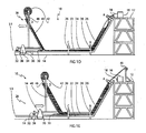
- Fig. 1 shows a first and currently preferred embodiment of a resin column impregnation plant
- Fig. 2 shows a perspective view of the impregnation plant of Fig. 1 .
Priority Applications (3)
| Application Number | Priority Date | Filing Date | Title |
|---|---|---|---|
| EP08018553A EP2189263A1 (de) | 2008-10-23 | 2008-10-23 | Vakuumfreie Imprägnieranlage |
| EP09755856A EP2358511A1 (de) | 2008-10-23 | 2009-10-23 | Vakuumfreie imprägnieranlage |
| PCT/EP2009/063968 WO2010046466A1 (en) | 2008-10-23 | 2009-10-23 | Vacuum-free impregnation plant |
Applications Claiming Priority (1)
| Application Number | Priority Date | Filing Date | Title |
|---|---|---|---|
| EP08018553A EP2189263A1 (de) | 2008-10-23 | 2008-10-23 | Vakuumfreie Imprägnieranlage |
Publications (1)
| Publication Number | Publication Date |
|---|---|
| EP2189263A1 true EP2189263A1 (de) | 2010-05-26 |
Family
ID=40385670
Family Applications (2)
| Application Number | Title | Priority Date | Filing Date |
|---|---|---|---|
| EP08018553A Ceased EP2189263A1 (de) | 2008-10-23 | 2008-10-23 | Vakuumfreie Imprägnieranlage |
| EP09755856A Withdrawn EP2358511A1 (de) | 2008-10-23 | 2009-10-23 | Vakuumfreie imprägnieranlage |
Family Applications After (1)
| Application Number | Title | Priority Date | Filing Date |
|---|---|---|---|
| EP09755856A Withdrawn EP2358511A1 (de) | 2008-10-23 | 2009-10-23 | Vakuumfreie imprägnieranlage |
Country Status (2)
| Country | Link |
|---|---|
| EP (2) | EP2189263A1 (de) |
| WO (1) | WO2010046466A1 (de) |
Cited By (1)
| Publication number | Priority date | Publication date | Assignee | Title |
|---|---|---|---|---|
| KR102492416B1 (ko) * | 2022-08-03 | 2023-01-27 | (주)신이앤씨 | 반전튜브 현장 함침장치 및 이를 이용한 반전튜브 현장 함침방법 |
Citations (5)
| Publication number | Priority date | Publication date | Assignee | Title |
|---|---|---|---|---|
| US4009063A (en) * | 1970-09-22 | 1977-02-22 | Insituform (Pipes And Structures) Limited | Method of lining a pipe |
| US5846602A (en) | 1996-09-17 | 1998-12-08 | Rothenberger Rorhsanierung Gmbh Industriestrasse 7 | Process and device for the production of a tube for lining pipe conduits and sewer systems |
| US20030138298A1 (en) * | 2000-11-14 | 2003-07-24 | Sanexen Environmental Services Inc. | Method for rehabilitating conduits |
| EP1547745A1 (de) * | 2003-12-23 | 2005-06-29 | BKP Berolina Polyester GmbH & Co. KG | Aushärtbarer Schlauch sowie Vorrichtung und Verfahren zu seiner Herstellung |
| EP1920913A1 (de) | 2006-11-06 | 2008-05-14 | Per Aarsleff A/S | Auskleidungsanordnung, Auskleidungsrohr, Verbundauskleidungsanordnung und erstarrtes Auskleidungsrohr |
-
2008
- 2008-10-23 EP EP08018553A patent/EP2189263A1/de not_active Ceased
-
2009
- 2009-10-23 WO PCT/EP2009/063968 patent/WO2010046466A1/en active Application Filing
- 2009-10-23 EP EP09755856A patent/EP2358511A1/de not_active Withdrawn
Patent Citations (5)
| Publication number | Priority date | Publication date | Assignee | Title |
|---|---|---|---|---|
| US4009063A (en) * | 1970-09-22 | 1977-02-22 | Insituform (Pipes And Structures) Limited | Method of lining a pipe |
| US5846602A (en) | 1996-09-17 | 1998-12-08 | Rothenberger Rorhsanierung Gmbh Industriestrasse 7 | Process and device for the production of a tube for lining pipe conduits and sewer systems |
| US20030138298A1 (en) * | 2000-11-14 | 2003-07-24 | Sanexen Environmental Services Inc. | Method for rehabilitating conduits |
| EP1547745A1 (de) * | 2003-12-23 | 2005-06-29 | BKP Berolina Polyester GmbH & Co. KG | Aushärtbarer Schlauch sowie Vorrichtung und Verfahren zu seiner Herstellung |
| EP1920913A1 (de) | 2006-11-06 | 2008-05-14 | Per Aarsleff A/S | Auskleidungsanordnung, Auskleidungsrohr, Verbundauskleidungsanordnung und erstarrtes Auskleidungsrohr |
Cited By (1)
| Publication number | Priority date | Publication date | Assignee | Title |
|---|---|---|---|---|
| KR102492416B1 (ko) * | 2022-08-03 | 2023-01-27 | (주)신이앤씨 | 반전튜브 현장 함침장치 및 이를 이용한 반전튜브 현장 함침방법 |
Also Published As
| Publication number | Publication date |
|---|---|
| WO2010046466A1 (en) | 2010-04-29 |
| EP2358511A1 (de) | 2011-08-24 |
Similar Documents
| Publication | Publication Date | Title |
|---|---|---|
| EP3444512B1 (de) | Konstruktion von rohren | |
| CN106985427B (zh) | 管子的构造 | |
| NO342248B1 (no) | Fremgangsmåte for å installere en herdet på stedet harpiksimpregnert kledning. | |
| NO339436B1 (no) | Harpiksimpregneringstårn for vulkanisert på stedet kledning | |
| CN101228388A (zh) | 现场固化内衬的空气翻转与蒸汽固化装置及方法 | |
| US10352016B2 (en) | Method and apparatus for sealing and structurally renewing a wall of a manhole | |
| JPH09254259A (ja) | マンホール用ライニング材及びマンホールライニング工法 | |
| EP2189263A1 (de) | Vakuumfreie Imprägnieranlage | |
| JP6010229B2 (ja) | 風力発電装置−ロータブレードの製造方法、並びにそのための中子型の製造方法 | |
| AU2009289184B2 (en) | Impregnation plant and method | |
| US5846602A (en) | Process and device for the production of a tube for lining pipe conduits and sewer systems | |
| KR100853165B1 (ko) | 경화용수지가 함침된 상·하수관 보강용 튜브 제조방법 및경화용수지 함침장치 | |
| KR100797621B1 (ko) | 가지관 보수기 | |
| KR101846531B1 (ko) | 배관보수용 튜브의 함침장치 | |
| US6054180A (en) | Method for impregnating a tubular resin-absorbable liner with resin | |
| CN104859159A (zh) | 铺放带偏转半径预浸料的装置及方法 | |
| EP2915656B1 (de) | Verfahren zur Herstellung einer Komponenten für eine Windturbine | |
| JP2020190139A (ja) | フォーム施工機、及びフォーム施工方法 | |
| KR100922596B1 (ko) | 관로 보수용 보수재의 제조장치 | |
| KR100948393B1 (ko) | 배관보수용 튜브의 함침장치 | |
| CN204725867U (zh) | 铺放带偏转半径预浸料的装置 | |
| JP6611689B2 (ja) | パイプの建造 | |
| KR102492416B1 (ko) | 반전튜브 현장 함침장치 및 이를 이용한 반전튜브 현장 함침방법 | |
| KR102150692B1 (ko) | 두께조절이 용이한 관거 보수보강 튜브 와인딩 장치 및 이를 포함하는 관거 보수보강 튜브 제조 시설 | |
| KR20050099432A (ko) | 공·수압 복합형 반전 삽입장치를 이용한 하수도 노후관의 열경화성 수지액 함침 pe 연질 부직포 보강튜브 삽입 보수공법. |
Legal Events
| Date | Code | Title | Description |
|---|---|---|---|
| PUAI | Public reference made under article 153(3) epc to a published international application that has entered the european phase |
Free format text: ORIGINAL CODE: 0009012 |
|
| AK | Designated contracting states |
Kind code of ref document: A1 Designated state(s): AT BE BG CH CY CZ DE DK EE ES FI FR GB GR HR HU IE IS IT LI LT LU LV MC MT NL NO PL PT RO SE SI SK TR |
|
| AX | Request for extension of the european patent |
Extension state: AL BA MK RS |
|
| STAA | Information on the status of an ep patent application or granted ep patent |
Free format text: STATUS: THE APPLICATION HAS BEEN REFUSED |
|
| 18R | Application refused |
Effective date: 20100710 |