EP2188537B1 - Blind rivet assembly and method of setting - Google Patents
Blind rivet assembly and method of setting Download PDFInfo
- Publication number
- EP2188537B1 EP2188537B1 EP08780344.1A EP08780344A EP2188537B1 EP 2188537 B1 EP2188537 B1 EP 2188537B1 EP 08780344 A EP08780344 A EP 08780344A EP 2188537 B1 EP2188537 B1 EP 2188537B1
- Authority
- EP
- European Patent Office
- Prior art keywords
- rivet
- mandrel
- setting
- head
- blind
- Prior art date
- Legal status (The legal status is an assumption and is not a legal conclusion. Google has not performed a legal analysis and makes no representation as to the accuracy of the status listed.)
- Active
Links
- 238000000034 method Methods 0.000 title claims description 4
- 230000000994 depressogenic effect Effects 0.000 claims description 2
- 238000007906 compression Methods 0.000 description 7
- 230000006835 compression Effects 0.000 description 7
- 229910000831 Steel Inorganic materials 0.000 description 2
- 230000000712 assembly Effects 0.000 description 2
- 238000000429 assembly Methods 0.000 description 2
- 238000010276 construction Methods 0.000 description 2
- 239000010959 steel Substances 0.000 description 2
- 235000008098 Oxalis acetosella Nutrition 0.000 description 1
- 240000007930 Oxalis acetosella Species 0.000 description 1
- XAGFODPZIPBFFR-UHFFFAOYSA-N aluminium Chemical compound [Al] XAGFODPZIPBFFR-UHFFFAOYSA-N 0.000 description 1
- 229910052782 aluminium Inorganic materials 0.000 description 1
- 238000005056 compaction Methods 0.000 description 1
- 238000005520 cutting process Methods 0.000 description 1
- 238000003780 insertion Methods 0.000 description 1
- 230000037431 insertion Effects 0.000 description 1
- 230000002452 interceptive effect Effects 0.000 description 1
- 238000012423 maintenance Methods 0.000 description 1
- 238000004519 manufacturing process Methods 0.000 description 1
- 238000004806 packaging method and process Methods 0.000 description 1
- 238000012856 packing Methods 0.000 description 1
- 230000000717 retained effect Effects 0.000 description 1
- 238000004904 shortening Methods 0.000 description 1
Images


Classifications
-
- B—PERFORMING OPERATIONS; TRANSPORTING
- B21—MECHANICAL METAL-WORKING WITHOUT ESSENTIALLY REMOVING MATERIAL; PUNCHING METAL
- B21J—FORGING; HAMMERING; PRESSING METAL; RIVETING; FORGE FURNACES
- B21J15/00—Riveting
- B21J15/02—Riveting procedures
- B21J15/04—Riveting hollow rivets mechanically
- B21J15/043—Riveting hollow rivets mechanically by pulling a mandrel
-
- F—MECHANICAL ENGINEERING; LIGHTING; HEATING; WEAPONS; BLASTING
- F16—ENGINEERING ELEMENTS AND UNITS; GENERAL MEASURES FOR PRODUCING AND MAINTAINING EFFECTIVE FUNCTIONING OF MACHINES OR INSTALLATIONS; THERMAL INSULATION IN GENERAL
- F16B—DEVICES FOR FASTENING OR SECURING CONSTRUCTIONAL ELEMENTS OR MACHINE PARTS TOGETHER, e.g. NAILS, BOLTS, CIRCLIPS, CLAMPS, CLIPS OR WEDGES; JOINTS OR JOINTING
- F16B19/00—Bolts without screw-thread; Pins, including deformable elements; Rivets
- F16B19/04—Rivets; Spigots or the like fastened by riveting
- F16B19/08—Hollow rivets; Multi-part rivets
- F16B19/10—Hollow rivets; Multi-part rivets fastened by expanding mechanically
- F16B19/1027—Multi-part rivets
- F16B19/1036—Blind rivets
- F16B19/1045—Blind rivets fastened by a pull - mandrel or the like
- F16B19/1054—Blind rivets fastened by a pull - mandrel or the like the pull-mandrel or the like being frangible
-
- Y—GENERAL TAGGING OF NEW TECHNOLOGICAL DEVELOPMENTS; GENERAL TAGGING OF CROSS-SECTIONAL TECHNOLOGIES SPANNING OVER SEVERAL SECTIONS OF THE IPC; TECHNICAL SUBJECTS COVERED BY FORMER USPC CROSS-REFERENCE ART COLLECTIONS [XRACs] AND DIGESTS
- Y10—TECHNICAL SUBJECTS COVERED BY FORMER USPC
- Y10T—TECHNICAL SUBJECTS COVERED BY FORMER US CLASSIFICATION
- Y10T29/00—Metal working
- Y10T29/49—Method of mechanical manufacture
- Y10T29/49826—Assembling or joining
- Y10T29/49908—Joining by deforming
- Y10T29/49938—Radially expanding part in cavity, aperture, or hollow body
- Y10T29/49943—Riveting
Definitions
- the present invention generally relates to rivets and more particularly to a blind rivet assembly.
- US 2007/0110540 A1 describes a blind rivet assembly, with an axially extending hollow tubular body having a tail end face at one end and a pre-formed radially enlarged flange at the other end.
- a stem of a mandrel extends co-axially through the hollow tubular body, wherein the mandrel has an enlarged head and a weakened portion adjacent the head. The mandrel head is breaking at the weakened portion while the mandrel is pulled through the rivet body.
- US 4,765,010 describes a blind fastener of the break-stem type, comprising a headed tubular body and an elongated stem disposed in the bore of the body.
- the stem comprises a plug and a stem-tail connected to the plug by a breakneck, which is concealed by overlapping lips.
- the stem breaks at the breakneck, allowing the stem-tail to be discarded and leaving the plug locked in the body.
- US 2004/0071525 A1 discloses a peel type blind rivet assembly for securement in an aperture of one or more workpieces.
- the assembly comprises a rivet with a tubular shell and a mandrel with a stem extending through the shell and having an enlarged head.
- the head comprises a plurality of axially extending cutting edges for engaging with the body shell. These edges serve to split the shell into a plurality of segments to engage with a remote side of the workpieces.
- the stem further comprises a weakened neck portion, which breaks when sufficient force is applied to the stem. While these constructions have significantly improved the industry, further improvements are desirable.
- a blind rivet assembly is provided.
- the blind rivet has ends that are received within countersinks in workpieces and a mandrel head is completely pulled through the rivet without being severed from a mandrel stem.
- the mandrel has one or more ribs located on an outwardly tapering shoulder.
- a method of making and setting rivets is also provided.
- the present invention blind rivet assembly is advantageous over conventional blind rivet assemblies since the ends of the present blind rivet are flush or below flush from the outside workpiece surfaces. This achieves a smaller packaging space for improved inner packing density of fastened components with less opportunity for snagging otherwise protruding rivet heads and flanges. Furthermore, the present invention blind rivet assembly does not employ a broken mandrel head. Therefore, assembly is less expensive and has a higher quality since the broken heads do not have to be located after setting, and the broken heads are not loose which can cause rattling and shorting of electrical circuits. Reducing setting loads are required for the pull-through mandrel versus a breakable head mandrel, thus improving the longevity of setting tools, extending times between routine maintenance and contributing to improved productivity.
- the blind rivet advantageously is set from only one side of the workpieces.
- blind rivet assembly 31 includes a blind rivet 33, a mandrel 35 and workpieces 37.
- Workpieces 37 are preferably component panels, boxes, cabinets or housings of electronic computer, electronic server or other such devices.
- Workpieces 37 include a tool-side outer surface 39 and an opposite blind-side outer surface 41 within which are countersunk depressions 43 joined by circular-cylindrical holes 45 located at the workpiece interface.
- Each countersink 43 has a generally frusto-conical shape with a total angle ⁇ equal to or between 120° and 90°, and more preferably between 110° and 90° total.
- Blind rivet 33 includes a body 51 and a tool-side flange 53.
- a frusto-conical outside surface 55 tapers along an outside of flange 53 and an outside surface 57 of body 51 has a circular-cylindrical shape.
- a through-bore 59 extends between a tool end face 61 and a blind or tail end 63 of blind rivet 33.
- Through-bore 59 has a generally constant inside diameter between ends 61 and 63 prior to rivet setting.
- Outside diameter ⁇ of flange 53 has a preferred dimension equal to or between 5.0 and 5.4 mm while an outside diameter ⁇ of rivet body 51 has a dimension equal to or between 3.08 mm and 2.9 mm.
- mandrel 35 includes an axially elongated stem 81 and a laterally enlarged head 83.
- Stem 81 is predominantly circular-cylindrical but locally interrupted by various depressions 85 and adjacent protrusions 87 which assist in securing the rivet onto the mandrel during shipping and tool feeding.
- a chamfered end 89 and extension 91 are located at an end of stem 81 opposite head 83 so as to assist in alignment with a setting tool.
- Head 83 includes a generally flat blind or tail end 101, and a shoulder 103.
- Shoulder 103 of the presently preferred embodiment is defined by a pair of differently angled and straight tapering surfaces 105 and 107. Tapering surfaces 105 and 107 are coaxial with each other and with stem 81.
- Four ribs 111 are located on shoulder 103 and are equi-distantly spaced around shoulder 103. Ribs 111 are elongated in a predominantly axially aligned direction but are offset angled essentially like shoulder 103.
- An outside diameter ⁇ of mandrel head 83 is preferably equal to or between 3.5 mm and 2.9 mm, and a nominal angle of the total mandrel shoulder ⁇ is preferably equal to or between 110° and 90° prior to rivet setting. Furthermore, an axial thickness of mandrel head 83, at a lip and not including the shoulder, is preferably equal to or between 1.0 mm and 0.35 mm before rivet setting. It is preferred that outside diameter ⁇ of mandrel head 83 is greater than outside diameter ⁇ of rivet body 51 to achieve proper hole filling and axial setting compression. Blind rivet 33 and mandrel 33 are also preferably made from grade SAE1006 steel.
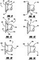
- Figure 10 illustrates an alternate embodiment mandrel 35a like the preferred embodiment, however, shoulder 103a includes straight tapering, frusto-conical surfaces 105a and 107a, but without ribs.
- Another alternate embodiment mandrel 35b is shown in Figure 11 .
- Mandrel 35b has a shoulder 103b including straight tapered, frusto-conical surfaces 105b and 107b like that of Figure 9 , and ribs 111b also like that of Figure 9 .
- a non-claimed alternate embodiment mandrel 35c is illustrated in Figure 12 .
- Shoulder 103c has a single angled frusto-conical taper in addition to the stepped spacing 121c of lip 123c. No ribs are employed with this exemplary embodiment.
- an alternate non-claimed embodiment mandrel 35d provides an arcuately curved taper at shoulder 103d, ribs 111d and inwardly stepped lip 123d.
- Alternate non-claimed embodiment Figure 14 has an arcuately tapered shoulder 103e, no ribs and the inward shoulder spacing relative to lip 123e.
- Figure 15 employs a non-claimed arcuately tapered shoulder 103f in combination with ribs 111f but no inward spacing of shoulder 103f relative to lip 123f.
- another non-claimed alternate embodiment mandrel 35g includes an arcuately tapered shoulder 103g but without ribs and without the inward shoulder-to-lip 123g spacing.
- an alternate non-claimed embodiment mandrel 35h includes a claimed embodiment of the end of the mandrel head having a concave curved surface 131 depressed below the nominal tail end 101h. This encourages lateral compression and folding of head 83h during rivet setting.
- Figure 18 alternately shows a non-claimed mandrel 35i with a claimed embodiment of the end of the mandrel head having a convex surface 133 outwardly curving from tail end 101i to change the folded characteristics of head 83i during rivet setting.
- a rivet setting tool 201 includes a piston rod 203, a jaw pusher 205, a compression spring 207 outwardly biasing the pusher 205, a set of jaws 209, a jaw case 211, an outer barrel 213 and a nose piece 215.
- Mandrel 35 and rivet 33 are pre-assembled together with an interference fit due to bulge 87 (see Figure 5 ) prior to insertion in setting tool 201. Thereafter, stem 81 of mandrel 35 is inserted into nose piece 215 and temporarily retained by jaws 209.
- rivet tool is located adjacent workpieces 37 such that the blind end of the blind rivet and mandrel are inserted through the corresponding hole in workpieces 37 such that tool-side flange 53 completely fits within the adjacent countersink 43 and the tool end of blind rivet 33 is predominantly flush or below flush outside surface 39 of the tool-side workpiece. It is noteworthy that there is a slight gap between the outside surface of the rivet body and the inside diameter of the workpiece hole before rivet setting.
- the preferred embodiment blind rivet assembly is shown in the set and fully installed condition.
- Mandrel head 83 and more particularly outwardly tapering shoulder 103 see Figures 8 and 21 ), outwardly expand blind end 63 of blind rivet 33 into the adjacent countersink 43 of the blind side workpiece 37.
- Further pulling through of mandrel head 83 causes rivet body to laterally expand and fill up hole 45 (see Figure 2 ) of workpieces 37 in an interference fit manner and at the same time the mandrel head folds, it remains intact as 83' and is extracted from the rivet.
- blind end 63 of blind rivet 33 is located flush or below flush (as shown) of the blind surface 41 of the corresponding workpiece 37 after rivet setting with an expanded, cup-like shape of through-bore 59 caused by the rivet setting.
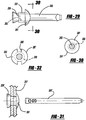
- ribs 111 gouge and indent axially elongated grooves 221 into the expanded tail end 63 of rivet 33, but without any significant severing of rivet body 33. These ribs cause a further outward bulging and splaying of blind end 63 between grooves 221 such as to form a shamrock-like pattern. This also creating more concentrated compression points at the grooved areas of the rivet body prior to lateral compression and compaction of ribs 111, shoulder 103 and lip 123 (again see Figure 8 ) during complete pull through of mandrel 81 relative to blind, rivet 33. Furthermore, the rib and shoulder configuration stretches out the thinning areas of blind end 63 of the rivet during setting.
- the post-rivet setting configuration of mandrel 81 showing the laterally folded and axially elongated head deformation, can be observed in Figure 25 .
- Figure 23 shows the set condition of blind end 63 of rivet 33 using the alternate mandrel 35a shown in Figure 10 .
- This embodiment is otherwise similar to that of Figures 27 and 28 except that no rib-created grooves nor shamrock pattern are created.
- blind rivet assembly 251 of the present invention employs a mandrel 253, blind rivet 255 and workpiece 257.
- Mandrel 253 is like any of the claimed and non-claimed mandrel embodiments previously disclosed hereinabove, including having a tapered shoulder with optional ribs.
- Blind rivet 251 has a circular-cylindrical body 259 and an arcuately domed or pan-head type tool-side flange 261.
- a constantly dimensioned through-bore 263 extends through the entire blind rivet 251.
- Blind rivet 251 and mandrel 253 are made from aluminum but may also be steel.
- workpieces 257 are aircraft panels but may alternately be other components.
- a setting tool completely pulls mandrel 253 through rivet 251 such that a blind end of rivet body 259 is outwardly deformed into a cup-like shape but not axially severed.
- the head of mandrel 253 is folded but not broken from the stem, like the previously disclosed mandrel embodiments.
- FIG 32 illustrates yet another blind rivet assembly embodiment.
- This blind rivet assembly 281 includes a mandrel like any of those previously disclosed hereinabove.
- a blind rivet 283 is like that shown in Figure 29 except a pair of opposed slots 285 radially extend inward from a periphery 287 of tool-side flange 289.
- Flange 289 is otherwise arcuately domed with a flat underside adjacent the rivet body, like that of Figure 29 .
- the set blind rivet 283 is employed to temporarily hold the aircraft workpieces together and thereafter drilled out or otherwise removed from the workpieces. Slots 285 assist in reducing curling drilled debris from the rivet otherwise interfering with the removal of the rivet or undesirably contaminating the component.
- the pull-through and unsevered mandrel advantageously prevents the need to find traditional severed mandrel heads from the fastened components or factory. Nevertheless, it should be appreciated that the blind rivet embodiments of Figures 29-32 do not achieve many of the desired advantages of the flush-style embodiments of the present invention.
Description
- The present invention generally relates to rivets and more particularly to a blind rivet assembly.
- It is known to set blind rivets with a mandrel. For example, reference should be made to
U.S. Patent No. 5,689,873 entitled "Tacking Fastener", upon which the preamble of claim 1 is based, and which issued to Luhm on November 25, 1997, Great Britain Patent No.286,471 2 150 661 US 2007/0110540 A1 describes a blind rivet assembly, with an axially extending hollow tubular body having a tail end face at one end and a pre-formed radially enlarged flange at the other end. A stem of a mandrel extends co-axially through the hollow tubular body, wherein the mandrel has an enlarged head and a weakened portion adjacent the head. The mandrel head is breaking at the weakened portion while the mandrel is pulled through the rivet body.US 4,765,010 describes a blind fastener of the break-stem type, comprising a headed tubular body and an elongated stem disposed in the bore of the body. The stem comprises a plug and a stem-tail connected to the plug by a breakneck, which is concealed by overlapping lips. When the stem is pulled in the tubular body, the stem breaks at the breakneck, allowing the stem-tail to be discarded and leaving the plug locked in the body.US 2004/0071525 A1 discloses a peel type blind rivet assembly for securement in an aperture of one or more workpieces. The assembly comprises a rivet with a tubular shell and a mandrel with a stem extending through the shell and having an enlarged head. The head comprises a plurality of axially extending cutting edges for engaging with the body shell. These edges serve to split the shell into a plurality of segments to engage with a remote side of the workpieces. In addition, the stem further comprises a weakened neck portion, which breaks when sufficient force is applied to the stem. While these constructions have significantly improved the industry, further improvements are desirable. - In accordance with the present invention, a blind rivet assembly is provided. The blind rivet has ends that are received within countersinks in workpieces and a mandrel head is completely pulled through the rivet without being severed from a mandrel stem. Preferably the mandrel has one or more ribs located on an outwardly tapering shoulder. A method of making and setting rivets is also provided.
- The present invention blind rivet assembly is advantageous over conventional blind rivet assemblies since the ends of the present blind rivet are flush or below flush from the outside workpiece surfaces. This achieves a smaller packaging space for improved inner packing density of fastened components with less opportunity for snagging otherwise protruding rivet heads and flanges. Furthermore, the present invention blind rivet assembly does not employ a broken mandrel head. Therefore, assembly is less expensive and has a higher quality since the broken heads do not have to be located after setting, and the broken heads are not loose which can cause rattling and shorting of electrical circuits. Reducing setting loads are required for the pull-through mandrel versus a breakable head mandrel, thus improving the longevity of setting tools, extending times between routine maintenance and contributing to improved productivity. Moreover, the blind rivet advantageously is set from only one side of the workpieces. The dimensional relationships and shapes of the blind rivet and mandrel are advantageous by maximizing fastening performance on a consistent basis, for example by allowing appropriate axial compression lengths and lateral expansion size hole filling of the set blind rivet in countersunk workpieces. Additional advantages and features of the present invention will become apparent from the following description and appended claims, taken in conjunction with the accompanying drawings.
-
-
Figure 1 is a partially exploded perspective view showing the preferred embodiment of a blind rivet assembly of the present invention, prior to rivet setting; -
Figure 2 is a cross-sectional view, taken along line 2-2 ofFigure 1 , showing workpieces employed in the preferred embodiment blind rivet assembly, prior to rivet setting. -
Figure 3 is a side elevational view showing a blind rivet and mandrel employed in the preferred embodiment blind rivet assembly, prior to rivet setting; -
Figure 4 is a cross-sectional view, taken along line 2-2 ofFigure 1 , showing the blind rivet employed in the preferred embodiment blind rivet assembly, prior to rivet setting; -
Figure 5 is a side elevational view showing the mandrel employed in the preferred embodiment blind rivet assembly, prior to rivet setting; -
Figure 6 is a cross-sectional view, taken along line 6-6 ofFigure 5 , showing the mandrel employed in the preferred embodiment blind rivet assembly, prior to rivet setting; -
Figure 7 is a cross-sectional view, taken along line 7-7 ofFigure 5 , showing the mandrel employed in the preferred embodiment blind rivet assembly, prior to rivet setting; -
Figure 8 is a fragmentary perspective view showing the mandrel employed in the preferred embodiment blind rivet assembly, prior to rivet setting; -
Figure 9 is a fragmentary side elevational view showing the mandrel employed in the preferred embodiment blind rivet assembly, prior to rivet setting; -
Figure 10 is a fragmentary side elevational view showing the mandrel employed in a first alternate embodiment blind rivet assembly, prior to rivet setting; -
Figure 11 is a fragmentary side elevational view showing the mandrel employed in a second alternate embodiment blind rivet assembly, prior to rivet setting; -
Figure 12 is a fragmentary side elevational view showing the mandrel employed in a third alternate non-claimed embodiment blind rivet assembly, prior to rivet setting; -
Figure 13 is a fragmentary side elevational view showing the mandrel employed in a fourth alternate non-claimed embodiment blind rivet assembly, prior to rivet setting; -
Figure 14 is a fragmentary side elevational view showing the mandrel employed in a fifth alternate non-claimed embodiment blind rivet assembly, prior to rivet setting; -
Figure 15 is a fragmentary side elevational view showing the mandrel employed in a sixth alternate non-claimed embodiment blind rivet assembly, prior to rivet setting; -
Figure 16 is a fragmentary side elevational view showing the mandrel employed in a seventh alternate non-claimed embodiment blind rivet assembly, prior to rivet setting; -
Figure 17 is a fragmentary side elevational view showing the claimed end of a mandrel employed in an eighth alternate non-claimed embodiment blind rivet assembly, prior to rivet setting; -
Figure 18 is a fragmentary side elevational view showing an alternate claimed end of a mandrel employed in a ninth alternate non-claimed embodiment blind rivet assembly, prior to rivet setting; -
Figure 19 is a perspective view showing the preferred embodiment blind rivet assembly protruding through the workpieces, prior to rivet setting; -
Figure 20 is a partially cross-sectional view, taken along line 2-2 ofFigure 1 , showing the preferred embodiment blind rivet assembly, including a setting tool, prior to rivet setting; -
Figure 21 is a partially cross-sectional view, taken along line 2-2 ofFigure 1 , showing the preferred embodiment blind rivet assembly, prior to rivet setting; -
Figure 22 is a partially fragmented, side elevational view showing the preferred embodiment blind rivet assembly, prior to rivet setting; -
Figure 23 is a perspective view showing the first alternate embodiment blind rivet assembly, after rivet setting; -
Figure 24 is a blind end elevational view showing the preferred embodiment blind rivet assembly slightly exaggerated, after rivet setting; -
Figure 25 is a perspective view showing the mandrel employed in the preferred embodiment blind rivet assembly, after rivet setting; -
Figure 26 is a cross-sectional view, taken along line 2-2 ofFigure 1 , showing the preferred embodiment blind rivet assembly, including the setting tool, after rivet setting; -
Figure 27 is a partially cross-sectional view, taken along line 2-2 ofFigure 1 , showing the preferred embodiment blind rivet assembly, after rivet setting; -
Figure 28 is a partially fragmented, side elevational view showing the preferred embodiment blind rivet assembly, after rivet setting; -
Figure 29 is a side elevational view showing a tenth alternate embodiment blind rivet assembly, with a non-claimed mandrel tapering shoulder, prior to rivet setting; -
Figure 30 is a cross-sectional view, taken along line 30-30 ofFigure 29 , showing the tenth alternate embodiment rivet assembly, prior to rivet setting; -
Figure 31 is a partially fragmented, side elevational view showing the tenth alternate embodiment blind rivet assembly, after rivet setting; and -
Figure 32 is a cross-sectional view, taken along line 30-30 ofFigure 29 , showing an eleventh alternate embodiment rivet assembly, prior to rivet setting. - The preferred embodiment of a
blind rivet assembly 31 of the present invention is shown inFigures 1-3 .Blind rivet assembly 31 includes ablind rivet 33, amandrel 35 andworkpieces 37.Workpieces 37 are preferably component panels, boxes, cabinets or housings of electronic computer, electronic server or other such devices.Workpieces 37 include a tool-sideouter surface 39 and an opposite blind-sideouter surface 41 within which are countersunkdepressions 43 joined by circular-cylindrical holes 45 located at the workpiece interface. Each countersink 43 has a generally frusto-conical shape with a total angle α equal to or between 120° and 90°, and more preferably between 110° and 90° total. -
Figures 3 and4 best illustrateblind rivet 33.Blind rivet 33 includes abody 51 and a tool-side flange 53. A frusto-conicaloutside surface 55 tapers along an outside offlange 53 and anoutside surface 57 ofbody 51 has a circular-cylindrical shape. A through-bore 59 extends between atool end face 61 and a blind ortail end 63 ofblind rivet 33. Through-bore 59 has a generally constant inside diameter between ends 61 and 63 prior to rivet setting. Outside diameter β offlange 53 has a preferred dimension equal to or between 5.0 and 5.4 mm while an outside diameter Φ ofrivet body 51 has a dimension equal to or between 3.08 mm and 2.9 mm. - Referring to
Figures 5-9 , the preferred embodiment ofmandrel 35 includes an axiallyelongated stem 81 and a laterallyenlarged head 83.Stem 81 is predominantly circular-cylindrical but locally interrupted byvarious depressions 85 andadjacent protrusions 87 which assist in securing the rivet onto the mandrel during shipping and tool feeding. Achamfered end 89 andextension 91 are located at an end ofstem 81opposite head 83 so as to assist in alignment with a setting tool. -
Head 83 includes a generally flat blind ortail end 101, and ashoulder 103.Shoulder 103 of the presently preferred embodiment is defined by a pair of differently angled and straight tapering surfaces 105 and 107. Taperingsurfaces stem 81. Fourribs 111 are located onshoulder 103 and are equi-distantly spaced aroundshoulder 103.Ribs 111 are elongated in a predominantly axially aligned direction but are offset angled essentially likeshoulder 103. An outside diameter Ω ofmandrel head 83 is preferably equal to or between 3.5 mm and 2.9 mm, and a nominal angle of the total mandrel shoulder Ψ is preferably equal to or between 110° and 90° prior to rivet setting. Furthermore, an axial thickness ofmandrel head 83, at a lip and not including the shoulder, is preferably equal to or between 1.0 mm and 0.35 mm before rivet setting. It is preferred that outside diameter Ω ofmandrel head 83 is greater than outside diameter Φ ofrivet body 51 to achieve proper hole filling and axial setting compression.Blind rivet 33 andmandrel 33 are also preferably made from grade SAE1006 steel. -
Figure 10 illustrates analternate embodiment mandrel 35a like the preferred embodiment, however,shoulder 103a includes straight tapering, frusto-conical surfaces alternate embodiment mandrel 35b is shown inFigure 11 .Mandrel 35b has ashoulder 103b including straight tapered, frusto-conical surfaces Figure 9 , andribs 111b also like that ofFigure 9 . Nevertheless, there is an inward spacing or step 121 between an outermost portion ofshoulder 103b and alip 123 ofhead 83b thereby causing an overhang. - A non-claimed
alternate embodiment mandrel 35c is illustrated inFigure 12 .Shoulder 103c has a single angled frusto-conical taper in addition to the steppedspacing 121c oflip 123c. No ribs are employed with this exemplary embodiment. Referring now toFigure 13 , an alternatenon-claimed embodiment mandrel 35d provides an arcuately curved taper atshoulder 103d,ribs 111d and inwardly steppedlip 123d. Alternate non-claimed embodimentFigure 14 has an arcuately taperedshoulder 103e, no ribs and the inward shoulder spacing relative tolip 123e.Figure 15 employs a non-claimed arcuatelytapered shoulder 103f in combination withribs 111f but no inward spacing ofshoulder 103f relative tolip 123f. As can be seen inFigure 16 , another non-claimedalternate embodiment mandrel 35g includes an arcuatelytapered shoulder 103g but without ribs and without the inward shoulder-to-lip 123g spacing. - Referring now to
Figure 17 , an alternatenon-claimed embodiment mandrel 35h includes a claimed embodiment of the end of the mandrel head having a concavecurved surface 131 depressed below thenominal tail end 101h. This encourages lateral compression and folding ofhead 83h during rivet setting.Figure 18 alternately shows anon-claimed mandrel 35i with a claimed embodiment of the end of the mandrel head having aconvex surface 133 outwardly curving fromtail end 101i to change the folded characteristics of head 83i during rivet setting. - Reference should now be made to
Figures 19-22 , where the rivet setting procedures and construction will be discussed. Arivet setting tool 201 includes apiston rod 203, ajaw pusher 205, acompression spring 207 outwardly biasing thepusher 205, a set ofjaws 209, ajaw case 211, anouter barrel 213 and anose piece 215.Mandrel 35 and rivet 33 are pre-assembled together with an interference fit due to bulge 87 (seeFigure 5 ) prior to insertion insetting tool 201. Thereafter, stem 81 ofmandrel 35 is inserted intonose piece 215 and temporarily retained byjaws 209. - Next, rivet tool is located
adjacent workpieces 37 such that the blind end of the blind rivet and mandrel are inserted through the corresponding hole inworkpieces 37 such that tool-side flange 53 completely fits within theadjacent countersink 43 and the tool end ofblind rivet 33 is predominantly flush or below flush outsidesurface 39 of the tool-side workpiece. It is noteworthy that there is a slight gap between the outside surface of the rivet body and the inside diameter of the workpiece hole before rivet setting. - Comparing the pre-rivet setting condition of
Figure 20 to the post-rivet setting condition ofFigure 26 , the stem of the mandrel is gripped between the jaws of settingtool 201 and the rivet flange is abutted by the nose piece. As the tool is activated, the piston rod is caused to retract by a piston actuator which inwardly urges the jaws due to the action of the jaw case. Approximately 1,500 newtons of force are used by the setting tool to pull the mandrel through the rivet, which is approximately 500 newtons less than necessary for breakable head-type mandrels. As the mandrel head is pulled into the rivet body, the head collapses and is pulled completely through the blind rivet without severing the mandrel head. At this stage, the power supply to the piston ceases and the piston returns to its ready state which opens the jaws, whereafter the spent mandrel is vacuum extracted into a mandrel collector bottle at the rear of the setting tool and discarded. Subsequently, the tool is then ready for the next rivet setting operation. - Referring to
Figures 24, 25 ,27 and 28 , the preferred embodiment blind rivet assembly is shown in the set and fully installed condition.Mandrel head 83 and more particularly outwardly tapering shoulder 103 (seeFigures 8 and21 ), outwardly expandblind end 63 ofblind rivet 33 into theadjacent countersink 43 of theblind side workpiece 37. Further pulling through ofmandrel head 83 causes rivet body to laterally expand and fill up hole 45 (seeFigure 2 ) ofworkpieces 37 in an interference fit manner and at the same time the mandrel head folds, it remains intact as 83' and is extracted from the rivet. The frusto-conical shapes of the countersinks and rivet flange, the outwardly expanded cup-like shape of the blind end of the rivet body, and the preferred dimensional relationships specified herein, further cause a desirable axial compression and shortening ofblind rivet 33 so as to cinch and tightly fasten togetherworkpieces 37 at the riveted joint.Blind end 63 ofblind rivet 33 is located flush or below flush (as shown) of theblind surface 41 of thecorresponding workpiece 37 after rivet setting with an expanded, cup-like shape of through-bore 59 caused by the rivet setting. - Moreover, ribs 111 (see
Figure 8 ) gouge and indent axially elongatedgrooves 221 into the expandedtail end 63 ofrivet 33, but without any significant severing ofrivet body 33. These ribs cause a further outward bulging and splaying ofblind end 63 betweengrooves 221 such as to form a shamrock-like pattern. This also creating more concentrated compression points at the grooved areas of the rivet body prior to lateral compression and compaction ofribs 111,shoulder 103 and lip 123 (again seeFigure 8 ) during complete pull through ofmandrel 81 relative to blind,rivet 33. Furthermore, the rib and shoulder configuration stretches out the thinning areas ofblind end 63 of the rivet during setting. The post-rivet setting configuration ofmandrel 81, showing the laterally folded and axially elongated head deformation, can be observed inFigure 25 . -
Figure 23 shows the set condition ofblind end 63 ofrivet 33 using thealternate mandrel 35a shown inFigure 10 . This embodiment is otherwise similar to that ofFigures 27 and 28 except that no rib-created grooves nor shamrock pattern are created. - Referring to
Figures 29-31 , another alternate embodimentblind rivet assembly 251 of the present invention employs amandrel 253, blind rivet 255 andworkpiece 257.Mandrel 253 is like any of the claimed and non-claimed mandrel embodiments previously disclosed hereinabove, including having a tapered shoulder with optional ribs.Blind rivet 251, however, has a circular-cylindrical body 259 and an arcuately domed or pan-head type tool-side flange 261. A constantly dimensioned through-bore 263 extends through the entireblind rivet 251.Blind rivet 251 andmandrel 253 are made from aluminum but may also be steel. Furthermore,workpieces 257 are aircraft panels but may alternately be other components. During rivet setting, a setting tool completely pullsmandrel 253 throughrivet 251 such that a blind end ofrivet body 259 is outwardly deformed into a cup-like shape but not axially severed. The head ofmandrel 253 is folded but not broken from the stem, like the previously disclosed mandrel embodiments. -
Figure 32 illustrates yet another blind rivet assembly embodiment. This blind rivet assembly 281 includes a mandrel like any of those previously disclosed hereinabove. Ablind rivet 283 is like that shown inFigure 29 except a pair ofopposed slots 285 radially extend inward from aperiphery 287 of tool-side flange 289.Flange 289 is otherwise arcuately domed with a flat underside adjacent the rivet body, like that ofFigure 29 . - The set
blind rivet 283 is employed to temporarily hold the aircraft workpieces together and thereafter drilled out or otherwise removed from the workpieces.Slots 285 assist in reducing curling drilled debris from the rivet otherwise interfering with the removal of the rivet or undesirably contaminating the component. For both of the embodiments ofFigures 29-32 , the pull-through and unsevered mandrel advantageously prevents the need to find traditional severed mandrel heads from the fastened components or factory. Nevertheless, it should be appreciated that the blind rivet embodiments ofFigures 29-32 do not achieve many of the desired advantages of the flush-style embodiments of the present invention. - While various embodiments of the present invention blind rivet assembly have been disclosed, it should be appreciated that other configurations may be employed. For example, more or less ribs can be provided although various advantages of the present invention may not be realized. Furthermore, any of the mandrel configurations disclosed herein can be mixed and matched with others depending upon the specific characteristics of the riveted joint desired although various advantages of the present invention may not be achieved. Moreover, alternate mandrel stem depressions and shapes can be used although various advantages of the present invention may not be achieved. While specific dimensional relationships are preferred, it should be appreciated that other dimensions may be used but that many of the advantages may not be achieved. Any other departures from the disclosed embodiments shall fall within the scope of the appended claims.
Claims (12)
- A rivet assembly comprising:at least one workpiece (37) having a first outer surface (39) and an opposite second outer surface (41) connected by a hole (45);a blind rivet (33) comprising a body (51) and a tool-side flange (53), the body (51) including a cylindrical outside surface (57) from the flange (53) to a blind end (63) prior to rivet setting, and a surface (55) of the flange (53) tapering outwardly from the outside surface (57) of the body; anda mandrel (35) comprising an elongated stem (81) extending through the rivet (33) prior to setting, a head (83) laterally larger than the stem (81) prior to rivet setting, and an outwardly tapering shoulder (103) located on the head (83) adjacent the stem (81);the head (83) being of the type completely pullable through the rivet (33) during rivet setting without severing the head (83) from the stem (81) of the mandrel (35), wherein the pulling through of the head (83) during setting causes the blind end (63) of the rivet body (51) to outwardly expand and the head (83) of the mandrel (35) to inwardly deform during rivet setting; characterised in that:a countersink (43) is located in each said outer surface (39, 41) of said at least one workpiece (37), said countersinks (43) being connected by said hole (45);the flange (53) of the rivet (33) is of the type adapted to be located in the adjacent countersink (43) after rivet setting; and said shoulder (103) of the mandrel (35) includes two differently angled frustoconical, tapered surfaces (105, 107).
- The rivet assembly of Claim 1, further comprising at least one rib (111) projecting from the shoulder (103) of the mandrel (35).
- The rivet assembly of Claim 2, wherein the at least one rib (111) comprises at least two ribs (111), the ribs (111) being elongated in a direction substantially coinciding with a direction of elongation of the stem (81), and the rivet body (51) is unsevered after the ribs (111) pass through the blind rivet (33) during rivet setting.
- The rivet assembly of any of Claims 2 and 3, wherein the rib (111) creates a depressed groove (221) in a bore of the rivet body (51) adjacent at least the blind end (63) during rivet setting.
- The rivet assembly of any of the preceding claims, wherein the at least one workpiece (37) includes a pair of electrical device components.
- The rivet assembly of Claim 5, wherein at least one of the electric device components (37) includes a computer housing.
- The rivet assembly of any of the preceding claims, further comprising an end (101) of the mandrel head (83) opposite the stem (81), said end (101) including a concave surface (131).
- The rivet assembly of any of the preceding claims, further comprising an end (101) of the mandrel head (83) opposite the stem (81), said end (101) including a convex surface (133).
- The rivet assembly of any of the preceding claims, wherein the rivet (33) and mandrel (35) have the following relationship before rivet setting:
an outside diameter of the mandrel head (83) is equal to or between 3.5 mm and 2.9 mm, and an outside diameter of the blind end of the rivet body (51) is equal to or between 3.08 mm and 2.9 mm. - The rivet assembly of any of the preceding claims, wherein an axial thickness of the mandrel head (83), not including the shoulder (103), is equal to or between 1.0 mm and 0.35 mm before rivet setting, and a nominal angle of the total mandrel shoulder (103) is equal to or between 110° and 90° as measured from one side to the other of the shoulder (103) before rivet setting.
- The rivet assembly of any of the preceding claims, further comprising a setting tool (201) operably setting the blind rivet (33) to the workpiece (37) from a single side of the workpiece, the setting tool (201) comprising at least one jaw (209) operably pulling the mandrel stem (81) and a nosepiece (215) operably abutting against the tool-side flange (53), and a piston of the tool (201) operably causing the mandrel (35) to be pulled through the rivet (33), the blind rivet (33) being attachable to the mandrel (35) through an interference fit before the mandrel (35) is inserted into the tool (201).
- A method of setting a rivet (33) to workpieces (37), the method comprising:(a) providing a rivet assembly according to claim 1;(b) locating the tool-side flange (53) of the blind rivet (33) within the first countersink (43) in the workpieces (37) substantially flush or below flush an adjacent first outside surface (39) of the workpieces (37); and(c) pulling the head (83) of the mandrel (35) completely through the rivet (33) during rivet setting, without severing the mandrel head (83) from the mandrel stem (81), in order to outwardly expand a tail end of the rivet into the second countersink (43) in the workpieces (37) substantially flush or below flush an adjacent second outside surface (41) of the workpieces (37), wherein the head (83) of the mandrel (35) inwardly deforms during rivet setting.
Applications Claiming Priority (2)
| Application Number | Priority Date | Filing Date | Title |
|---|---|---|---|
| US11/890,302 US7824141B2 (en) | 2007-08-03 | 2007-08-03 | Blind rivet |
| PCT/US2008/009203 WO2009020543A1 (en) | 2007-08-03 | 2008-07-29 | Blind rivet |
Publications (3)
| Publication Number | Publication Date |
|---|---|
| EP2188537A1 EP2188537A1 (en) | 2010-05-26 |
| EP2188537A4 EP2188537A4 (en) | 2014-09-17 |
| EP2188537B1 true EP2188537B1 (en) | 2020-11-18 |
Family
ID=40336779
Family Applications (1)
| Application Number | Title | Priority Date | Filing Date |
|---|---|---|---|
| EP08780344.1A Active EP2188537B1 (en) | 2007-08-03 | 2008-07-29 | Blind rivet assembly and method of setting |
Country Status (6)
| Country | Link |
|---|---|
| US (2) | US7824141B2 (en) |
| EP (1) | EP2188537B1 (en) |
| JP (1) | JP5607527B2 (en) |
| KR (1) | KR20100055445A (en) |
| CN (2) | CN101784801B (en) |
| WO (1) | WO2009020543A1 (en) |
Families Citing this family (18)
| Publication number | Priority date | Publication date | Assignee | Title |
|---|---|---|---|---|
| JP2013502551A (en) * | 2009-08-24 | 2013-01-24 | ニューフレイ リミテッド ライアビリティ カンパニー | Blind rivet |
| DE102009040102B4 (en) * | 2009-09-04 | 2011-07-07 | Miele & Cie. KG, 33332 | Rivet and basket insert |
| US8696719B2 (en) | 2010-06-03 | 2014-04-15 | Tarsus Medical Inc. | Methods and devices for treating hallux valgus |
| DE102010017296A1 (en) | 2010-06-08 | 2011-12-08 | Newfrey Llc | Blind rivet and mounting arrangement with a blind rivet |
| JP2012077769A (en) * | 2010-09-30 | 2012-04-19 | Nippon Pop Rivets & Fasteners Ltd | Blind rivet and fastening method thereof |
| US9138219B2 (en) | 2010-12-29 | 2015-09-22 | Tarsus Medical Inc. | Methods and devices for treating a syndesmosis injury |
| CN103225644A (en) * | 2012-01-30 | 2013-07-31 | 湖北博士隆科技有限公司 | Hollow rivet with double-side countersunk head |
| CN102562753A (en) * | 2012-02-08 | 2012-07-11 | 无锡安士达五金有限公司 | Rivet stem of non-fracture mute blind rivet |
| EP2689867A1 (en) * | 2012-07-27 | 2014-01-29 | GESIPA Blindniettechnik GmbH | Connection element and setting device for a connection element |
| US10087969B2 (en) | 2013-05-02 | 2018-10-02 | Ornit Agriculture Industry Business And Management Agricultural Cooperative Association Ltd. | Blind rivet |
| CN105443538A (en) * | 2016-01-11 | 2016-03-30 | 太仓市德浩紧固件有限公司 | Double-protection type fastening rivet |
| CN106015243A (en) * | 2016-07-05 | 2016-10-12 | 任宝全 | Manufacturing method of gradual thinning structure riveting nail for blind hole |
| CN106050845A (en) * | 2016-07-26 | 2016-10-26 | 中国电子科技集团公司第十研究所 | Method for connecting two thin plates by using countersunk riveting bushing |
| CN106168240A (en) * | 2016-08-24 | 2016-11-30 | 江苏昊嘉不锈钢标准件有限公司 | A kind of high intensity riveting column |
| WO2019089360A1 (en) | 2017-10-31 | 2019-05-09 | Allfast Fastening Systems | Chip break bolt head |
| CN111771065B (en) | 2017-12-27 | 2022-12-13 | 全速紧固系统公司 | Positioning fastener and installation method thereof |
| CN114776681B (en) * | 2021-01-22 | 2024-03-22 | 宾科精密部件(中国)有限公司 | Riveting method and riveting structure |
| US20230173589A1 (en) * | 2021-12-03 | 2023-06-08 | Howmet Aerospace Inc. | Blind fastener |
Citations (1)
| Publication number | Priority date | Publication date | Assignee | Title |
|---|---|---|---|---|
| GB286471A (en) * | 1927-03-22 | 1928-03-08 | Armstrong Whitworth Co Eng | Improvements in and relating to rivets and riveting |
Family Cites Families (161)
| Publication number | Priority date | Publication date | Assignee | Title |
|---|---|---|---|---|
| GB348631A (en) | 1929-11-13 | 1931-05-13 | Hall & Kay Ltd | Improvements in or relating to metal sockets, bushes, ferrules, rivets and the like |
| FR724509A (en) * | 1931-10-14 | 1932-04-28 | Liore Et Olivier Ets | Riveting device |
| US1996128A (en) | 1933-11-21 | 1935-04-02 | Dardelet Threadlock Corp | Fastener |
| US2146461A (en) | 1937-01-06 | 1939-02-07 | Aviat Developments Ltd | Method of riveting |
| US2183543A (en) | 1937-06-21 | 1939-12-19 | Carl W Cherry | Rivet and method of applying the same |
| GB532899A (en) | 1939-08-18 | 1941-02-03 | Stanley Thomas Johnson | Improvements in or relating to tubular rivets |
| US2328023A (en) | 1942-05-16 | 1943-08-31 | Bocjl Corp | Blind rivet |
| US2371423A (en) | 1943-04-17 | 1945-03-13 | B F B Engineers Inc | Mandrel extrusion rivet |
| US2371452A (en) | 1944-03-14 | 1945-03-13 | Jr Milton H Lees | Rivet |
| US2384321A (en) | 1944-03-29 | 1945-09-04 | Jr Milton H Lees | Rivet construction |
| US2546602A (en) * | 1945-05-14 | 1951-03-27 | Cherry Rivet Company | Rivet with self-locking mandrel |
| GB642664A (en) | 1947-05-23 | 1950-09-06 | Aviat Developments Ltd | Improvements in or relating to feeding appliances |
| US2774098A (en) | 1952-08-19 | 1956-12-18 | Arthur J Tieri | Ophthalmic mounting hinge |
| NL99009C (en) | 1954-02-16 | |||
| BE555416A (en) | 1956-02-28 | |||
| GB891460A (en) | 1957-03-25 | 1962-03-14 | Avdel Ltd | Improvements in or relating to blind rivets |
| US2885798A (en) | 1957-12-23 | 1959-05-12 | United Shoe Machinery Corp | Shoes, heels and lift attachments therefor |
| US3144158A (en) | 1961-06-13 | 1964-08-11 | Gobin Daude | Device for setting rivets in a wall whitch is accessible on one side only |
| GB1029654A (en) * | 1961-06-19 | 1966-05-18 | Avdel Ltd | Improvements in or relating to fasteners for use in, and to methods of, blind riveting of apertured members |
| US3148578A (en) | 1961-10-16 | 1964-09-15 | Townsend Company | Rivet and method of riveting |
| NL128418C (en) | 1963-08-30 | |||
| FR1494693A (en) | 1965-05-19 | 1967-09-08 | Olympic Screw & Rivet Corp | Blind rivets |
| GB1145124A (en) | 1965-08-12 | 1969-03-12 | Avdel Ltd | Fastening devices |
| GB1183049A (en) | 1966-09-16 | 1970-03-04 | Avdel Ltd | Riveting Apparatus |
| US3459447A (en) * | 1966-12-13 | 1969-08-05 | Huck Mfg Co | Flush fastener for panel assembly including soft core material |
| US3424051A (en) | 1967-03-20 | 1969-01-28 | Huck Mfg Co | Hollow fastener and plug assembly |
| US3438301A (en) | 1967-04-10 | 1969-04-15 | Emhart Corp | Hollow rivet and pull-stem assembly for blind fastening or the like |
| US3460429A (en) | 1967-04-19 | 1969-08-12 | Jack La Torre | Expansible fastener with expander therefor |
| GB1228781A (en) * | 1967-08-09 | 1971-04-21 | ||
| FR1553116A (en) | 1967-11-30 | 1969-01-10 | ||
| US3460428A (en) * | 1968-03-07 | 1969-08-12 | Nat Screw & Mfg Co The | Threaded fastener with torque limiting drive portions |
| GB1323873A (en) | 1969-07-28 | 1973-07-18 | Avdel Ltd | Tubular rivet |
| US3835688A (en) | 1970-04-30 | 1974-09-17 | J King | Apparatus and method for sizing holes |
| JPS5142793B1 (en) * | 1970-08-11 | 1976-11-17 | ||
| GB1427511A (en) | 1972-02-14 | 1976-03-10 | Avdel Ltd | Method and apparatus for blind riveting |
| IT980234B (en) | 1972-04-17 | 1974-09-30 | Olympic Fastening Systems | IMPROVEMENT IN BLIND RIVETS |
| US3750518A (en) | 1972-06-07 | 1973-08-07 | Illinois Tool Works | Self-drilling blind rivet |
| US3915055A (en) | 1972-10-30 | 1975-10-28 | Lloyd Sylvester Binns | Blind rivet having counterbored sleeve head of double-angle configuration |
| US3949535A (en) | 1973-01-17 | 1976-04-13 | King John O Jun | Coldworked joint held by seamless tubular member |
| US4164807A (en) | 1974-03-19 | 1979-08-21 | King John O Jun | Method of forming a coldworked joint |
| US3875649A (en) * | 1973-01-17 | 1975-04-08 | King John O Jun | Coldworking method and apparatus with frangible head flange |
| US3975786A (en) | 1973-02-05 | 1976-08-24 | Textron, Inc. | Method of forming a rivet of titanium-columbium alloy |
| GB1495592A (en) | 1974-01-18 | 1977-12-21 | Raymond A | Securing members |
| US3922586A (en) | 1974-04-01 | 1975-11-25 | Ite Imperial Corp | Ground fault detecting power outlet |
| GB1548880A (en) | 1975-07-23 | 1979-07-18 | Tucker Fasteners Ltd | Blind riveting |
| JPS5239964U (en) * | 1976-07-22 | 1977-03-22 | ||
| CA1096666A (en) | 1976-12-10 | 1981-03-03 | Dieter Mauer | Fastening |
| US4236429A (en) | 1976-12-30 | 1980-12-02 | Gernot Dolch | Blind rivet |
| US4405273A (en) * | 1977-07-19 | 1983-09-20 | Huck Manufacturing Company | Blind fasteners |
| GB1572269A (en) | 1978-03-17 | 1980-07-30 | Advel Ltd | Jaw assembly for blind riveting apparatus |
| GB2051289B (en) * | 1979-06-07 | 1983-10-12 | Kraemer L | Blind rivet |
| US4407619A (en) | 1979-09-20 | 1983-10-04 | Olympic Fastening Systems | Blind fastener with deformable clamping means |
| US4388031A (en) | 1980-10-03 | 1983-06-14 | Rodgers Earl T | Blind fastener device |
| US4541032A (en) | 1980-10-21 | 1985-09-10 | B/K Patent Development Company, Inc. | Modular electrical shunts for integrated circuit applications |
| US4466048A (en) | 1980-10-21 | 1984-08-14 | B/K Patent Development Co., Inc. | Electrical shunts for integrated circuit applications |
| US4447944A (en) | 1982-06-16 | 1984-05-15 | The United States Of America As Represented By The Secretary Of The Navy | Method of forming a tubular rivet in fastening relation to a plurality of laminates |
| US4507706A (en) | 1982-06-18 | 1985-03-26 | Paccar Inc. | Plug-in instrumentation system |
| US4497603A (en) | 1982-06-28 | 1985-02-05 | Usm Corporation | Pull through blind rivet |
| US4863325A (en) | 1982-09-28 | 1989-09-05 | Huck Manufacturing Company | Two piece blind fastener with lock spindle construction |
| US4473914A (en) | 1982-09-30 | 1984-10-02 | Huck Manufacturing Company | Method and apparatus for manufacturing a stop and lock shoulder for a blind fastener sleeve |
| US4541761A (en) | 1983-09-26 | 1985-09-17 | Usm Corporation | Easily removed blind rivet |
| US4585382A (en) | 1983-12-01 | 1986-04-29 | Usm Corporation | Easily removable rivet with tab |
| US4836728A (en) | 1983-11-15 | 1989-06-06 | Emhart Industries, Inc. | Blind-riveting assembly |
| DE3343786A1 (en) | 1983-12-03 | 1985-06-13 | Tucker Gmbh, 6300 Giessen | BLIND RIVET BY DRAW TYPE |
| US4659271A (en) | 1984-02-23 | 1987-04-21 | Monogram Industries, Inc. | Flush break blind fastener |
| GB8517659D0 (en) | 1985-07-12 | 1985-08-21 | Avdel Ltd | Self-plugging blind fastener |
| US4702655A (en) | 1985-08-27 | 1987-10-27 | Huck Manufacturing Company | Fastening system including an improved interference fit blind fastener and method of manufacture |
| FR2587421B1 (en) | 1985-09-18 | 1987-11-20 | Garonne Ets Auriol & Cie | SEMI-TUBULAR RIVET |
| DE3612501A1 (en) | 1986-04-14 | 1987-10-22 | Tucker Gmbh | Metal blind rivet |
| IL82949A0 (en) | 1986-06-26 | 1987-12-20 | Textron Inc | Blind fastener with self-locking collar |
| DE3639870A1 (en) | 1986-11-21 | 1988-06-01 | Daimler Benz Ag | SECURITY DEVICE FOR DETECTING THE UNAUTHORIZED OPENING OF A HOUSING |
| US4736560A (en) | 1986-12-01 | 1988-04-12 | Engineered Construction Components (America) | Peel rivet |
| GB8702155D0 (en) * | 1987-01-30 | 1987-03-04 | Avdel Ltd | Break-stem blind rivet |
| US4858067A (en) | 1987-11-18 | 1989-08-15 | Crl Electronics, Inc. | Modular electronic control housing assembly |
| DE68902323T2 (en) | 1988-02-12 | 1993-01-28 | Avdel Systems Ltd | BLIND RIVET. |
| GB2220454A (en) | 1988-05-27 | 1990-01-10 | Avdel Ltd | Blind rivet |
| US4904133A (en) | 1988-07-11 | 1990-02-27 | Textron Inc. | Fastener with integral locking means |
| US4893390A (en) | 1988-09-01 | 1990-01-16 | Snyder General Corporation | Method and expander for manufacturing a furnace heat exchanger and plate assembly |
| DE3909143A1 (en) | 1989-03-21 | 1990-09-27 | Basf Ag | METHOD FOR EXAMINING SURFACE STRUCTURES |
| GB8916702D0 (en) | 1989-07-21 | 1989-09-06 | Avdel Systems Ltd | Repetition riveting apparatus |
| GB2234024B (en) | 1989-07-22 | 1993-09-29 | Dunlop Ltd | Carbon composite laminated structures |
| JPH0348106U (en) | 1989-09-18 | 1991-05-08 | Nec Corp | Blind rivet |
| US4969785A (en) | 1989-11-01 | 1990-11-13 | Textron, Inc. | Fastener mandrel and method |
| US5651172A (en) * | 1990-01-26 | 1997-07-29 | Ste. Ateliers De La Haute-Garonne-Ets Auriol Et Cie | Process for the assembly of materials and riveting member for carrying out the process |
| DE4003136A1 (en) | 1990-02-02 | 1991-08-08 | Boellhoff & Co | Mandrel for closing blind rivet - has specially shaped transition surface between head and shank |
| US5006024A (en) | 1990-03-05 | 1991-04-09 | George Siebol | Dual-lock blind fastener |
| US5044850A (en) | 1990-05-11 | 1991-09-03 | Avdel Corporation | Self plugging blind rivet |
| GB9015648D0 (en) | 1990-07-17 | 1990-09-05 | Tucker Fasteners Ltd | Improved blind riveting assembly |
| US5054977A (en) | 1990-09-18 | 1991-10-08 | Automatic Fastener Corporation | Self plugging blind rivet |
| DE4100709A1 (en) | 1991-01-11 | 1992-07-16 | Emhart Inc | BLIND RIVET NUT WITH TIE PIN |
| US5403135A (en) | 1991-01-11 | 1995-04-04 | Emhart Inc. | Blind rivet nut with pulling mandrel |
| GB2251909A (en) | 1991-01-18 | 1992-07-22 | Avdel Systems Ltd | Self-plugging blind rivet |
| GB9203251D0 (en) | 1992-02-15 | 1992-04-01 | Emhart Inc | Blind pin fixing |
| US5378098A (en) | 1992-12-09 | 1995-01-03 | Textron Inc. | Hole filling blind rivet |
| JPH071318U (en) | 1993-06-04 | 1995-01-10 | ポップリベット・ファスナー株式会社 | Fasteners that can be installed from one direction |
| JPH07113364B2 (en) * | 1993-06-22 | 1995-12-06 | 有限会社新城製作所 | Blind rivet mandrel and its manufacturing equipment |
| US5333980A (en) | 1993-07-15 | 1994-08-02 | Textron, Inc. | Buckling semi-solid rivet |
| IL106817A0 (en) | 1993-08-27 | 1993-12-08 | Ornit | Blind rivet |
| US5476350A (en) | 1993-10-28 | 1995-12-19 | Avdel Corporation - Systems Division | Slotted push-in rivet and method of riveting |
| GB9324378D0 (en) | 1993-11-26 | 1994-01-12 | Emhart Inc | Blind rivet |
| DE4343171C2 (en) | 1993-12-17 | 1996-08-08 | Gesipa Blindniettechnik | Blind rivet and process for its manufacture |
| JP3048106B2 (en) | 1994-03-18 | 2000-06-05 | 株式会社富士通ゼネラル | Electric carpet |
| US5443344A (en) | 1994-09-12 | 1995-08-22 | Iowa State University Research Foundation, Inc. | Method and apparatus for attaching two members together from one side thereof |
| GB9501849D0 (en) | 1995-01-31 | 1995-03-22 | Avdel Systems Ltd | Method of fastening members of an assembly |
| GB9504095D0 (en) | 1995-03-01 | 1995-04-19 | Emhart Inc | Improved blind rivet |
| US5569006A (en) | 1995-05-11 | 1996-10-29 | Textron, Inc. | Bulb fastener |
| GB9519476D0 (en) | 1995-09-23 | 1995-11-22 | Emhart Inc | Improved blind rivet |
| US5689873A (en) * | 1996-01-11 | 1997-11-25 | Allfast Fastening Systems, Inc. | Tacking fastener |
| USRE38664E1 (en) | 1996-01-11 | 2004-11-30 | Allfast Fastening Systems, Inc. | Method for creating a hole for a permanent fastener that replaces a tacking fastener |
| US5701231A (en) | 1996-05-03 | 1997-12-23 | Citicorp Development Center, Inc. | Personal computer enclosure with peripheral device mounting system |
| US5741099A (en) | 1996-05-17 | 1998-04-21 | Asar Group, Inc. | Self tapping blind setting rivet assembly |
| US5915901A (en) | 1996-07-12 | 1999-06-29 | Asar Group, Inc. | Blind setting rivet assembly |
| DE19646668A1 (en) | 1996-11-12 | 1998-05-14 | Sfs Ind Holding Ag | Fastener insertable in a blind hole |
| GB9624710D0 (en) | 1996-11-28 | 1997-01-15 | Milladale Ltd | Blind rivet and method of making the same |
| US5743691A (en) | 1997-02-03 | 1998-04-28 | Textron Inc. | Clinch-type fastener member |
| US5881989A (en) | 1997-03-04 | 1999-03-16 | Apple Computer, Inc. | Audio enclosure assembly mounting system and method |
| ES2206902T3 (en) * | 1997-03-11 | 2004-05-16 | Titus International Plc | DEVICES FOR THE FORMATION OF UNIONS. |
| US6276050B1 (en) | 1998-07-20 | 2001-08-21 | Emhart Inc. | Riveting system and process for forming a riveted joint |
| US5889648A (en) | 1997-07-25 | 1999-03-30 | Storage Technology Corporation | Seismic cabinet |
| DE19732517A1 (en) | 1997-07-29 | 1999-02-04 | Bergner Richard Gmbh Co | Process for producing a flush mandrel break at the setting head height on mandrel break blind rivets with remaining mandrel |
| DE29716899U1 (en) * | 1997-09-22 | 1997-11-27 | Avdel Verbindungselemente | Broken mandrel rivet and device for its processing |
| GB2330390B (en) | 1997-10-10 | 2001-10-17 | Avdel Textron Ltd | Blind riveting |
| US6007287A (en) | 1997-10-30 | 1999-12-28 | Mcdonnell Douglas Corporation | Deformable head fastener |
| US5960667A (en) | 1997-12-23 | 1999-10-05 | Emhart Inc. | Ball device for setting blind riverts |
| JPH11284357A (en) | 1998-03-27 | 1999-10-15 | Mitsubishi Electric Corp | Electronic apparatus casing |
| US5982610A (en) | 1998-05-27 | 1999-11-09 | Reltec Corporation | Multisided communication distribution cabinet having adjustable tie rod |
| AU7423698A (en) | 1998-06-04 | 1999-12-20 | Synthes Ag, Chur | Surgical blind rivet with closing element |
| US6171038B1 (en) | 1998-11-12 | 2001-01-09 | Textron Inc. | Tapered shank rivet |
| GB2346943A (en) | 1999-02-19 | 2000-08-23 | Emhart Inc | Blind rivet with circumferential grooves and axial ribs |
| GB2347474A (en) | 1999-03-03 | 2000-09-06 | Emhart Inc | A blind rivet assembly |
| JP3201379B2 (en) | 1999-03-26 | 2001-08-20 | 日本電気株式会社 | Front plate mold mounting structure for electronic circuit package |
| JP2000346023A (en) | 1999-06-01 | 2000-12-12 | Shinjo Seisakusho:Kk | Blind rivet |
| JP2001020924A (en) * | 1999-07-06 | 2001-01-23 | Shinjo Seisakusho:Kk | Blind rivet |
| DE29919824U1 (en) | 1999-11-12 | 2000-06-21 | Volz Michael Albert | Housing for the rowing machine of vehicle models |
| DE19956675A1 (en) | 1999-11-25 | 2001-05-31 | Daimler Chrysler Ag | Plastic housing for holding an assembly with electrical and electronic components on a circuit board |
| GB2357128A (en) | 1999-12-07 | 2001-06-13 | Emhart Inc | Blind rivet |
| US6854940B2 (en) | 1999-12-08 | 2005-02-15 | Newfrey Llc | Closed-end blind rivet with a crimped shank and method of manufacture thereof |
| GB2358053B (en) | 1999-12-14 | 2003-11-19 | Textron Fastening Syst Ltd | Insert and method of installation thereof |
| US6637995B1 (en) | 2000-02-09 | 2003-10-28 | Patrick Michel White | Super-elastic rivet assembly |
| JP2001252741A (en) * | 2000-03-07 | 2001-09-18 | Ricoh Co Ltd | Tightening tool |
| JP2001328425A (en) | 2000-05-19 | 2001-11-27 | Nippon Pop Rivets & Fasteners Ltd | Molding installing device |
| JP2002018544A (en) | 2000-07-07 | 2002-01-22 | Nippon Pop Rivets & Fasteners Ltd | Tightening device for blind rivet or the like |
| JP3967069B2 (en) | 2000-09-05 | 2007-08-29 | ポップリベット・ファスナー株式会社 | Connector |
| US6443322B1 (en) | 2000-10-19 | 2002-09-03 | Fujitsu Network Communications, Inc. | Wall mount enclosure having installation features for multiple separately-installed components |
| US6754066B2 (en) | 2000-10-27 | 2004-06-22 | Liebert Corporation | UPS cabinet and method of assembly |
| GB2371344A (en) | 2001-01-23 | 2002-07-24 | Frederick Arthur Summerlin | Blind rivet |
| US6881898B2 (en) | 2001-03-02 | 2005-04-19 | Liebert Corporation | Remote distribution cabinet |
| US20030082025A1 (en) | 2001-10-18 | 2003-05-01 | Ralph Luhm | Blind fasteners and installation methods and apparatus |
| WO2003038292A2 (en) | 2001-11-01 | 2003-05-08 | Newfrey Llc | Self-drilling pull-through blind rivet and methods of and apparatus for the assembly and setting thereof |
| US6746192B2 (en) | 2001-12-27 | 2004-06-08 | Textron Inc. | Anti-rotation tacking rivet having ribs |
| JP2003214414A (en) * | 2002-01-22 | 2003-07-30 | Nippon Pop Rivets & Fasteners Ltd | Blind rivet |
| US6898918B2 (en) | 2002-02-25 | 2005-05-31 | Textron Inc. | Honeycomb rivet |
| GB2388412A (en) * | 2002-05-08 | 2003-11-12 | Emhart Llc | Blind rivet |
| GB2389397B (en) * | 2002-06-06 | 2005-08-03 | Emhart Llc | Peel-type blind rivet |
| GB2389398B (en) | 2002-06-06 | 2005-08-03 | Emhart Llc | Peel-type blind rivet |
| US6751841B2 (en) | 2002-06-10 | 2004-06-22 | Sun Microsystems, Inc. | Riveting method |
| GB2392716B (en) * | 2002-09-09 | 2005-09-07 | Emhart Llc | Self-piercing blind fastener |
| CA2516052C (en) | 2003-05-14 | 2011-07-05 | Textron Fastening Systems Limited | Blind fastener and method of removing it from a workpiece |
| JP4468711B2 (en) * | 2004-02-16 | 2010-05-26 | ポップリベット・ファスナー株式会社 | Blind rivet |
| GB2426802B (en) | 2005-05-31 | 2008-07-16 | Newfrey Llc | A blind rivet, removal system and removal method |
| AT501877B1 (en) | 2005-05-31 | 2007-09-15 | Sumanjit Dr Ing Singh | RIVET |
-
2007
- 2007-08-03 US US11/890,302 patent/US7824141B2/en active Active
-
2008
- 2008-07-29 EP EP08780344.1A patent/EP2188537B1/en active Active
- 2008-07-29 WO PCT/US2008/009203 patent/WO2009020543A1/en active Application Filing
- 2008-07-29 CN CN2008801017784A patent/CN101784801B/en active Active
- 2008-07-29 JP JP2010519234A patent/JP5607527B2/en active Active
- 2008-07-29 KR KR1020107004647A patent/KR20100055445A/en not_active Application Discontinuation
- 2008-07-29 CN CN201310250724.7A patent/CN103398066B/en active Active
-
2010
- 2010-10-07 US US12/899,595 patent/US8366363B2/en active Active
Patent Citations (1)
| Publication number | Priority date | Publication date | Assignee | Title |
|---|---|---|---|---|
| GB286471A (en) * | 1927-03-22 | 1928-03-08 | Armstrong Whitworth Co Eng | Improvements in and relating to rivets and riveting |
Also Published As
| Publication number | Publication date |
|---|---|
| EP2188537A4 (en) | 2014-09-17 |
| EP2188537A1 (en) | 2010-05-26 |
| CN103398066A (en) | 2013-11-20 |
| US8366363B2 (en) | 2013-02-05 |
| JP2010535988A (en) | 2010-11-25 |
| US20110027042A1 (en) | 2011-02-03 |
| US20090031549A1 (en) | 2009-02-05 |
| WO2009020543A1 (en) | 2009-02-12 |
| CN101784801B (en) | 2013-06-12 |
| CN101784801A (en) | 2010-07-21 |
| US7824141B2 (en) | 2010-11-02 |
| KR20100055445A (en) | 2010-05-26 |
| CN103398066B (en) | 2015-11-25 |
| JP5607527B2 (en) | 2014-10-15 |
Similar Documents
| Publication | Publication Date | Title |
|---|---|---|
| EP2188537B1 (en) | Blind rivet assembly and method of setting | |
| EP2176557B1 (en) | Blind rivet | |
| US7937821B2 (en) | Blind rivet method | |
| US4355934A (en) | Self-plugging blind rivet | |
| EP0344005B1 (en) | Blind rivet | |
| EP0536957A1 (en) | Self-plugging blind rivet | |
| EP1623126B1 (en) | Blind fastener and method of removing it from a workpiece | |
| US5741099A (en) | Self tapping blind setting rivet assembly | |
| CN103534494A (en) | Splined fastener | |
| EP1021260B1 (en) | Blind riveting | |
| US4936725A (en) | Blind shear-ring fastener and method | |
| AU2001295714B2 (en) | Blind fastener | |
| US5131107A (en) | Method of making a blind fastener | |
| US4002099A (en) | Rivet | |
| GB2060110A (en) | Self-plugging Blind Rivet | |
| US5580202A (en) | Crowned solid rivet | |
| EP0728950A1 (en) | Method of securing members together and fastener therefor | |
| WO2003058075A2 (en) | Blind rivet with hollow head | |
| GB1603241A (en) | Rivet and method of riveting |
Legal Events
| Date | Code | Title | Description |
|---|---|---|---|
| PUAI | Public reference made under article 153(3) epc to a published international application that has entered the european phase |
Free format text: ORIGINAL CODE: 0009012 |
|
| 17P | Request for examination filed |
Effective date: 20100225 |
|
| AK | Designated contracting states |
Kind code of ref document: A1 Designated state(s): AT BE BG CH CY CZ DE DK EE ES FI FR GB GR HR HU IE IS IT LI LT LU LV MC MT NL NO PL PT RO SE SI SK TR |
|
| AX | Request for extension of the european patent |
Extension state: AL BA MK RS |
|
| A4 | Supplementary search report drawn up and despatched |
Effective date: 20140821 |
|
| RIC1 | Information provided on ipc code assigned before grant |
Ipc: F16B 19/08 20060101AFI20140814BHEP |
|
| RAP1 | Party data changed (applicant data changed or rights of an application transferred) |
Owner name: NEWFREY LLC |
|
| STAA | Information on the status of an ep patent application or granted ep patent |
Free format text: STATUS: EXAMINATION IS IN PROGRESS |
|
| 17Q | First examination report despatched |
Effective date: 20180208 |
|
| GRAP | Despatch of communication of intention to grant a patent |
Free format text: ORIGINAL CODE: EPIDOSNIGR1 |
|
| STAA | Information on the status of an ep patent application or granted ep patent |
Free format text: STATUS: GRANT OF PATENT IS INTENDED |
|
| INTG | Intention to grant announced |
Effective date: 20200528 |
|
| GRAS | Grant fee paid |
Free format text: ORIGINAL CODE: EPIDOSNIGR3 |
|
| GRAA | (expected) grant |
Free format text: ORIGINAL CODE: 0009210 |
|
| STAA | Information on the status of an ep patent application or granted ep patent |
Free format text: STATUS: THE PATENT HAS BEEN GRANTED |
|
| AK | Designated contracting states |
Kind code of ref document: B1 Designated state(s): AT BE BG CH CY CZ DE DK EE ES FI FR GB GR HR HU IE IS IT LI LT LU LV MC MT NL NO PL PT RO SE SI SK TR |
|
| AX | Request for extension of the european patent |
Extension state: AL BA MK RS |
|
| REG | Reference to a national code |
Ref country code: GB Ref legal event code: FG4D |
|
| REG | Reference to a national code |
Ref country code: CH Ref legal event code: EP |
|
| REG | Reference to a national code |
Ref country code: DE Ref legal event code: R096 Ref document number: 602008063469 Country of ref document: DE |
|
| REG | Reference to a national code |
Ref country code: IE Ref legal event code: FG4D |
|
| REG | Reference to a national code |
Ref country code: AT Ref legal event code: REF Ref document number: 1336092 Country of ref document: AT Kind code of ref document: T Effective date: 20201215 |
|
| REG | Reference to a national code |
Ref country code: AT Ref legal event code: MK05 Ref document number: 1336092 Country of ref document: AT Kind code of ref document: T Effective date: 20201118 |
|
| REG | Reference to a national code |
Ref country code: NL Ref legal event code: MP Effective date: 20201118 |
|
| PG25 | Lapsed in a contracting state [announced via postgrant information from national office to epo] |
Ref country code: GR Free format text: LAPSE BECAUSE OF FAILURE TO SUBMIT A TRANSLATION OF THE DESCRIPTION OR TO PAY THE FEE WITHIN THE PRESCRIBED TIME-LIMIT Effective date: 20210219 Ref country code: PT Free format text: LAPSE BECAUSE OF FAILURE TO SUBMIT A TRANSLATION OF THE DESCRIPTION OR TO PAY THE FEE WITHIN THE PRESCRIBED TIME-LIMIT Effective date: 20210318 Ref country code: NO Free format text: LAPSE BECAUSE OF FAILURE TO SUBMIT A TRANSLATION OF THE DESCRIPTION OR TO PAY THE FEE WITHIN THE PRESCRIBED TIME-LIMIT Effective date: 20210218 Ref country code: FI Free format text: LAPSE BECAUSE OF FAILURE TO SUBMIT A TRANSLATION OF THE DESCRIPTION OR TO PAY THE FEE WITHIN THE PRESCRIBED TIME-LIMIT Effective date: 20201118 |
|
| PG25 | Lapsed in a contracting state [announced via postgrant information from national office to epo] |
Ref country code: SE Free format text: LAPSE BECAUSE OF FAILURE TO SUBMIT A TRANSLATION OF THE DESCRIPTION OR TO PAY THE FEE WITHIN THE PRESCRIBED TIME-LIMIT Effective date: 20201118 Ref country code: PL Free format text: LAPSE BECAUSE OF FAILURE TO SUBMIT A TRANSLATION OF THE DESCRIPTION OR TO PAY THE FEE WITHIN THE PRESCRIBED TIME-LIMIT Effective date: 20201118 Ref country code: LV Free format text: LAPSE BECAUSE OF FAILURE TO SUBMIT A TRANSLATION OF THE DESCRIPTION OR TO PAY THE FEE WITHIN THE PRESCRIBED TIME-LIMIT Effective date: 20201118 Ref country code: BG Free format text: LAPSE BECAUSE OF FAILURE TO SUBMIT A TRANSLATION OF THE DESCRIPTION OR TO PAY THE FEE WITHIN THE PRESCRIBED TIME-LIMIT Effective date: 20210218 Ref country code: AT Free format text: LAPSE BECAUSE OF FAILURE TO SUBMIT A TRANSLATION OF THE DESCRIPTION OR TO PAY THE FEE WITHIN THE PRESCRIBED TIME-LIMIT Effective date: 20201118 Ref country code: IS Free format text: LAPSE BECAUSE OF FAILURE TO SUBMIT A TRANSLATION OF THE DESCRIPTION OR TO PAY THE FEE WITHIN THE PRESCRIBED TIME-LIMIT Effective date: 20210318 |
|
| REG | Reference to a national code |
Ref country code: LT Ref legal event code: MG9D |
|
| PG25 | Lapsed in a contracting state [announced via postgrant information from national office to epo] |
Ref country code: HR Free format text: LAPSE BECAUSE OF FAILURE TO SUBMIT A TRANSLATION OF THE DESCRIPTION OR TO PAY THE FEE WITHIN THE PRESCRIBED TIME-LIMIT Effective date: 20201118 |
|
| PG25 | Lapsed in a contracting state [announced via postgrant information from national office to epo] |
Ref country code: EE Free format text: LAPSE BECAUSE OF FAILURE TO SUBMIT A TRANSLATION OF THE DESCRIPTION OR TO PAY THE FEE WITHIN THE PRESCRIBED TIME-LIMIT Effective date: 20201118 Ref country code: CZ Free format text: LAPSE BECAUSE OF FAILURE TO SUBMIT A TRANSLATION OF THE DESCRIPTION OR TO PAY THE FEE WITHIN THE PRESCRIBED TIME-LIMIT Effective date: 20201118 Ref country code: RO Free format text: LAPSE BECAUSE OF FAILURE TO SUBMIT A TRANSLATION OF THE DESCRIPTION OR TO PAY THE FEE WITHIN THE PRESCRIBED TIME-LIMIT Effective date: 20201118 Ref country code: SK Free format text: LAPSE BECAUSE OF FAILURE TO SUBMIT A TRANSLATION OF THE DESCRIPTION OR TO PAY THE FEE WITHIN THE PRESCRIBED TIME-LIMIT Effective date: 20201118 Ref country code: LT Free format text: LAPSE BECAUSE OF FAILURE TO SUBMIT A TRANSLATION OF THE DESCRIPTION OR TO PAY THE FEE WITHIN THE PRESCRIBED TIME-LIMIT Effective date: 20201118 |
|
| REG | Reference to a national code |
Ref country code: DE Ref legal event code: R097 Ref document number: 602008063469 Country of ref document: DE |
|
| PG25 | Lapsed in a contracting state [announced via postgrant information from national office to epo] |
Ref country code: DK Free format text: LAPSE BECAUSE OF FAILURE TO SUBMIT A TRANSLATION OF THE DESCRIPTION OR TO PAY THE FEE WITHIN THE PRESCRIBED TIME-LIMIT Effective date: 20201118 |
|
| PLBE | No opposition filed within time limit |
Free format text: ORIGINAL CODE: 0009261 |
|
| STAA | Information on the status of an ep patent application or granted ep patent |
Free format text: STATUS: NO OPPOSITION FILED WITHIN TIME LIMIT |
|
| 26N | No opposition filed |
Effective date: 20210819 |
|
| PG25 | Lapsed in a contracting state [announced via postgrant information from national office to epo] |
Ref country code: IT Free format text: LAPSE BECAUSE OF FAILURE TO SUBMIT A TRANSLATION OF THE DESCRIPTION OR TO PAY THE FEE WITHIN THE PRESCRIBED TIME-LIMIT Effective date: 20201118 Ref country code: NL Free format text: LAPSE BECAUSE OF FAILURE TO SUBMIT A TRANSLATION OF THE DESCRIPTION OR TO PAY THE FEE WITHIN THE PRESCRIBED TIME-LIMIT Effective date: 20201118 |
|
| PG25 | Lapsed in a contracting state [announced via postgrant information from national office to epo] |
Ref country code: ES Free format text: LAPSE BECAUSE OF FAILURE TO SUBMIT A TRANSLATION OF THE DESCRIPTION OR TO PAY THE FEE WITHIN THE PRESCRIBED TIME-LIMIT Effective date: 20201118 Ref country code: SI Free format text: LAPSE BECAUSE OF FAILURE TO SUBMIT A TRANSLATION OF THE DESCRIPTION OR TO PAY THE FEE WITHIN THE PRESCRIBED TIME-LIMIT Effective date: 20201118 |
|
| REG | Reference to a national code |
Ref country code: CH Ref legal event code: PL |
|
| PG25 | Lapsed in a contracting state [announced via postgrant information from national office to epo] |
Ref country code: MC Free format text: LAPSE BECAUSE OF FAILURE TO SUBMIT A TRANSLATION OF THE DESCRIPTION OR TO PAY THE FEE WITHIN THE PRESCRIBED TIME-LIMIT Effective date: 20201118 |
|
| REG | Reference to a national code |
Ref country code: BE Ref legal event code: MM Effective date: 20210731 |
|
| PG25 | Lapsed in a contracting state [announced via postgrant information from national office to epo] |
Ref country code: LI Free format text: LAPSE BECAUSE OF NON-PAYMENT OF DUE FEES Effective date: 20210731 Ref country code: CH Free format text: LAPSE BECAUSE OF NON-PAYMENT OF DUE FEES Effective date: 20210731 |
|
| PG25 | Lapsed in a contracting state [announced via postgrant information from national office to epo] |
Ref country code: IS Free format text: LAPSE BECAUSE OF FAILURE TO SUBMIT A TRANSLATION OF THE DESCRIPTION OR TO PAY THE FEE WITHIN THE PRESCRIBED TIME-LIMIT Effective date: 20210318 Ref country code: LU Free format text: LAPSE BECAUSE OF NON-PAYMENT OF DUE FEES Effective date: 20210729 |
|
| PG25 | Lapsed in a contracting state [announced via postgrant information from national office to epo] |
Ref country code: IE Free format text: LAPSE BECAUSE OF NON-PAYMENT OF DUE FEES Effective date: 20210729 Ref country code: BE Free format text: LAPSE BECAUSE OF NON-PAYMENT OF DUE FEES Effective date: 20210731 |
|
| PG25 | Lapsed in a contracting state [announced via postgrant information from national office to epo] |
Ref country code: HU Free format text: LAPSE BECAUSE OF FAILURE TO SUBMIT A TRANSLATION OF THE DESCRIPTION OR TO PAY THE FEE WITHIN THE PRESCRIBED TIME-LIMIT; INVALID AB INITIO Effective date: 20080729 Ref country code: CY Free format text: LAPSE BECAUSE OF FAILURE TO SUBMIT A TRANSLATION OF THE DESCRIPTION OR TO PAY THE FEE WITHIN THE PRESCRIBED TIME-LIMIT Effective date: 20201118 |
|
| PGFP | Annual fee paid to national office [announced via postgrant information from national office to epo] |
Ref country code: FR Payment date: 20230620 Year of fee payment: 16 |
|
| P01 | Opt-out of the competence of the unified patent court (upc) registered |
Effective date: 20230912 |
|
| PGFP | Annual fee paid to national office [announced via postgrant information from national office to epo] |
Ref country code: GB Payment date: 20230608 Year of fee payment: 16 |
|
| PGFP | Annual fee paid to national office [announced via postgrant information from national office to epo] |
Ref country code: DE Payment date: 20230607 Year of fee payment: 16 |