US5378098A - Hole filling blind rivet - Google Patents
Hole filling blind rivet Download PDFInfo
- Publication number
- US5378098A US5378098A US08/132,502 US13250293A US5378098A US 5378098 A US5378098 A US 5378098A US 13250293 A US13250293 A US 13250293A US 5378098 A US5378098 A US 5378098A
- Authority
- US
- United States
- Prior art keywords
- sleeve
- stem
- shoulder
- lock ring
- fastener
- Prior art date
- Legal status (The legal status is an assumption and is not a legal conclusion. Google has not performed a legal analysis and makes no representation as to the accuracy of the status listed.)
- Expired - Lifetime
Links
- 239000000463 material Substances 0.000 claims abstract description 59
- 238000000034 method Methods 0.000 claims description 5
- 238000005429 filling process Methods 0.000 abstract 1
- 238000010008 shearing Methods 0.000 description 10
- 239000002184 metal Substances 0.000 description 4
- 230000000153 supplemental effect Effects 0.000 description 4
- 238000009434 installation Methods 0.000 description 3
- RGCLLPNLLBQHPF-HJWRWDBZSA-N phosphamidon Chemical compound CCN(CC)C(=O)C(\Cl)=C(/C)OP(=O)(OC)OC RGCLLPNLLBQHPF-HJWRWDBZSA-N 0.000 description 3
- 239000000956 alloy Substances 0.000 description 2
- 229910045601 alloy Inorganic materials 0.000 description 2
- 238000004513 sizing Methods 0.000 description 2
- 238000013459 approach Methods 0.000 description 1
- 230000015572 biosynthetic process Effects 0.000 description 1
- 238000004519 manufacturing process Methods 0.000 description 1
- 239000000203 mixture Substances 0.000 description 1
- 230000002028 premature Effects 0.000 description 1
Images


Classifications
-
- F—MECHANICAL ENGINEERING; LIGHTING; HEATING; WEAPONS; BLASTING
- F16—ENGINEERING ELEMENTS AND UNITS; GENERAL MEASURES FOR PRODUCING AND MAINTAINING EFFECTIVE FUNCTIONING OF MACHINES OR INSTALLATIONS; THERMAL INSULATION IN GENERAL
- F16B—DEVICES FOR FASTENING OR SECURING CONSTRUCTIONAL ELEMENTS OR MACHINE PARTS TOGETHER, e.g. NAILS, BOLTS, CIRCLIPS, CLAMPS, CLIPS OR WEDGES; JOINTS OR JOINTING
- F16B19/00—Bolts without screw-thread; Pins, including deformable elements; Rivets
- F16B19/04—Rivets; Spigots or the like fastened by riveting
- F16B19/08—Hollow rivets; Multi-part rivets
- F16B19/10—Hollow rivets; Multi-part rivets fastened by expanding mechanically
- F16B19/1027—Multi-part rivets
- F16B19/1036—Blind rivets
- F16B19/1045—Blind rivets fastened by a pull - mandrel or the like
- F16B19/1054—Blind rivets fastened by a pull - mandrel or the like the pull-mandrel or the like being frangible
-
- Y—GENERAL TAGGING OF NEW TECHNOLOGICAL DEVELOPMENTS; GENERAL TAGGING OF CROSS-SECTIONAL TECHNOLOGIES SPANNING OVER SEVERAL SECTIONS OF THE IPC; TECHNICAL SUBJECTS COVERED BY FORMER USPC CROSS-REFERENCE ART COLLECTIONS [XRACs] AND DIGESTS
- Y10—TECHNICAL SUBJECTS COVERED BY FORMER USPC
- Y10T—TECHNICAL SUBJECTS COVERED BY FORMER US CLASSIFICATION
- Y10T29/00—Metal working
- Y10T29/49—Method of mechanical manufacture
- Y10T29/49826—Assembling or joining
- Y10T29/49947—Assembling or joining by applying separate fastener
- Y10T29/49954—Fastener deformed after application
Definitions
- the present invention relates to blind fasteners including a stem and sleeve for securing workpieces together, a stem lock ring, and a means for filling varying sized workpiece openings.
- Blind fasteners are utilized in fastening workpieces in which only one side of the workpiece is accessible.
- One such fastener described in U.S. Pat. No. 5,131,107, issued to Pratt, et al, includes a stem and fastener body or sleeve which are inserted as a unit into aligned openings in workpieces.
- the stem is an elongated body having one end or tail designed for gripping by a pulling tool.
- the opposite end of the stem has an enlarged head.
- a shear ring is mounted on the end of the stem near the head, and a lock ring is located near the middle of the stem.
- the sleeve has a preformed head which engages the accessible side of the workpieces, and a tail which is designed for engagement of the blind side of the workpieces.
- the stem is inserted in the tubular body with the shear ring engaging the body tail and the stem tail protruding beyond the fastener body head.
- the stem and fastener body are inserted into the workpiece opening until the head of the fastener body engages the workpiece.
- the pulling tool is used to grasp the stem tail, and a force is applied to pull the stem through the sleeve with the tool nose reacting against the fastener body head.
- the bulbing portion of the shear ring slides within the tail of the fastener body, causing the tail to bulb radially outwardly.
- the shear ring is constructed such that after the bulbing is completed and a predetermined compressive force is applied to the workpieces through the shear ring and the bulbed tail, the shear ring separates from an anchor portion of the ring.
- the lock ring encounters an anvil on the pulling tool, causing the lock ring to be compressed into a small recess at the end of the bore in the fastener body.
- continued pulling increases the load causing the tail of the stem to break away at a break groove located beyond the lock ring at that point.
- the fastening procedure is then complete.
- the radial pressure from the stem against the reduced diameter portion of the fastener body creates a tight fit between the stem and the fastener body, and has improved the fit between the fastener and the workpieces.
- the workpieces are held securely together by the tension in the fastener body.
- the stem is captured within the fastener body by the shear ring and the stem head at one end, and the deformed lock ring at the other.
- U.S. Pat. No. 4,627,775 issued to Dixon discloses a fastener which provides hole fill capability with formation of a lock ring. That patent describes a blind fastener having a pin and sleeve arrangement, but does not employ a preformed lock ring. Instead, major interference is created between the pin and the sleeve causing expansion of the sleeve to fill the gap between the sleeve and the workpieces. This interference also results in sleeve material being extruded into a lock groove to form a lock between the pin and sleeve.
- An annular extruding land is formed on the pin adjacent the lock groove and on the side of the stem towards the fastener head.
- the extruding land interferes with the inner wall of the sleeve. This causes the sleeve to expand outwardly and fill any space between the outside of the sleeve and the workpieces.
- the land extrudes material from the wall of the sleeve. This material is pushed ahead of the land into the lock groove.
- a stop land encounters the surface of an installation tool anvil, and further pulling causes the serrated end of the pin to separate at a break notch. At this time, the material extruded from the sleeve sufficiently fills the lock groove so as to prevent removal of the pin from the sleeve.
- One drawback of the device described in the Dixon patent is that the action necessary to create the locking ring is made difficult when the sleeve is made of a very tough metal or alloy. If the sleeve is made of a particularly durable alloy or metal, the pulling force necessary to extrude the sleeve material may be so high that the pin severs at the break groove before installation. Related to that, considerable interference is needed to provide enough material for workpiece hole fill and to provide the stem locking function.
- U.S. Pat. No. 2,466,811 issued to Huck discloses a fastener where a preformed lock ring is a breakaway portion of the outer axial end of the sleeve head instead of an internally formed ring.
- the Huck design provides a reservoir of sorts, by utilizing a sleeve counterbore adjacent the sleeve head.
- a stem shoulder 25 may carry a small amount of metal with it into the counterbore 21 to be ironed out against the wall of the counterbore and to prevent its movement into an adjacent locking recess in the sleeve head for the lock ring.
- it is difficult for the stem shoulder to move sleeve metal from the area of initial interference to the sleeve counterbore 21 because sleeve material between the shoulder and the counterbore is in the way.
- FIGS. 1-6 of this application disclose a fastener which is disclosed and claimed in the parent application Ser. No. 987,659.
- This fastener includes a sleeve, and an elongated stem having at one end a serrated tail, and at the other end an enlarged head.
- the stem and the sleeve form a reservoir adjacent the shoulder for receiving excess sleeve material extruded during installation.
- the stem further has a locking groove adjacent the reservoir to receive a lock ring.
- the sleeve interior bore diameter near the sleeve tail is sized to receive the stem readily, but narrows at a shoulder located midway along the bore to interfere with a shoulder on the stem.
- the fastener with the stem in the sleeve, is inserted into aligned openings in workpieces.
- a pulling tool is used to pull the stem in a direction which is out of the workpieces, with the tool engaging an anvil on the sleeve head.
- the shear ring encounters the tail of the sleeve, the ring sliding into the tail and causing it to bulb outwardly. Further pulling causes the shear ring to shear when the bulbed tail engages the workpiece, a portion of the ring remaining with the stem, and the bulbing portion of the ring sliding on the outside of the stem, maintaining pressure on the tail.
- the shoulder of the stem encounters the shoulder in the sleeve.
- the sleeve will be enlarged radially outward to fill the workpiece hole.
- the shoulder material will be sheared or extruded from the sleeve and be deposited into the reservoir in the stem which is adjacent the stem shoulder.
- the lock ring will encounter the anvil located flush with the head of the sleeve. As continued pulling occurs, the lock ring is deformed, filling the recess in the sleeve head. As increased force is applied, the stem severs at a break notch in the stem. The fastener thus secures the workpieces together, any gap originally present between the sleeve and workpieces is eliminated, and the stem is locked to the sleeve.
- the reservoir of this fastener may provide supplemental locking.
- the reservoir adjoins the stem lock ring groove. Since in the extreme tolerance and clearance condition all extruded sleeve material is used for hole fill, the lock ring volume is selected so that satisfactory stem locking is obtained with only the lock ring.
- a blind fastener stem is provided a shoulder which will enlarge a sleeve to fill a workpiece hole while removing excess material from the interior of the sleeve.
- the stem includes an annular reservoir open to the stem shoulder to receive the excess sleeve material not used to fill the clearance between the sleeve and the workpiece when the fastener is set.
- the volume of the reservoir is less than the volume of an adjacent lock ring groove in the stem, but sufficient to accommodate all of the excess material in the maximum interference condition between the stem shoulder and the sleeve, and the sleeve and the workpiece.
- the reservoir groove is positioned between the stem shoulder and the stem lock groove.
- the stem includes a reduced diameter portion which slides within a reduced diameter portion of the sleeve head.
- the boundary between the reservoir groove and the lock ring groove creates a lock ring forming shoulder on the stem.
- the lock ring forming shoulder engages the reduced diameter portion of the sleeve head, and material is extruded from that sleeve portion into the lock ring groove.
- FIG. 1 is a cross-sectional side view of a blind fastener in a workpiece, and yet to be installed; the top half of the drawing illustrating the fastener as used with thinner workpieces, and the lower half of the drawing illustrating the fastener as used with thicker workpieces.
- FIG. 1a is an enlarged cross-sectional view of the fastener of FIG. 1, in the area marked 1a.
- FIG. 2 is a cross-sectional side view of the fastener of FIG. 1 when the stem is partially installed and the shear pin has begun to bulb the tail of the sleeve outwardly.
- FIG. 2a is an enlarged cross-sectional view of the fastener of FIG. 2, in the area marked 2a.
- FIG. 3 is a cross-sectional side view of the fastener of FIG. 1 when the stem is partially installed and interference between the stem and sleeve has caused the sleeve to radially expand.
- FIG. 3a is an enlarged cross-sectional view of the fastener of FIG. 3, in the area marked 3a.
- FIG. 4 is a cross-sectional side view of the fastener of FIG. 1 when fully installed.
- FIG. 4a is an enlarged cross-sectional view of the fastener of FIG. 4, in the area marked 4a.
- FIG. 5 is an enlarged cross-sectional view of the blind fastener of the invention yet to be installed, illustrating the reservoir when formed adjacent a modified lock ring.
- FIG. 6 is a cross-sectional view illustrating a reservoir having a shallow rectangular shape.
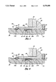
- FIG. 7 is a cross-sectional side view of the blind fastener of the invention in a workpiece, and yet to be installed; the top half of the drawing illustrating the fastener as used with thinner workpieces, and the lower half of the drawing illustrating the fastener as used with thicker workpieces.
- FIG. 7a is an enlarged cross-sectional view of the fastener of FIG. 7, in the area marked 7a.
- FIG. 8 is a cross-sectional side view of the fastener of FIG. 7 when the stem is partially installed and the shear pin has begun to bulb the tail of the sleeve outwardly.
- FIG. 8a is an enlarged cross-sectional view of the fastener of FIG. 8, in the area marked 8a.
- FIG. 9 is a cross-sectional side view of the fastener of FIG. 7 when the stem is partially installed and interference between the stem and sleeve has caused the sleeve to radially expand.
- FIG. 9a is an enlarged cross-sectional view of the fastener of FIG. 9, in the area marked 9a.
- FIG. 10 is a cross-sectional side view of the fastener of FIG. 7 when fully installed.
- FIG. 10a is an enlarged cross-sectional view of the fastener of FIG. 10, in the area marked 10a.
- a blind fastener 20 comprising a tubular sleeve 22 and a stem 24 mounted through aligned workpiece openings.
- the workpieces 26 may be of a thickness varying from a predetermined minimum as shown in the upper half of the figure, to a predetermined maximum thickness as shown in the lower half of the figure.
- the fastener 20 has grip length compensation to accommodate such variations.
- the sleeve 22 as shown has a head 28 at one end in contact with the accessible side of the workpieces 26.
- a tail 30 of the sleeve 22, located opposite the head 28, has an outwardly tapered or beveled inner diameter. As seen, the sleeve 22 protrudes beyond the blind side of the workpieces 26.
- the sleeve 22 has a bore having a larger diameter portion 21a which extends from the tail 30 towards the head 28.
- the bore also has a reduced diameter portion 21b creating a shoulder 21c spaced from the top of the manufactured head 28 a distance about equal to the outer diameter of the sleeve 22.
- the exact location of the shoulder 21c is selected such that when the fastener 20 is used with thicker workpieces 26, any gap between the sleeve portion 21a and workpieces 26, will be closed by the bulbing action of the tail 30. Any gap in the area of the reduced diameter portion 21b will be closed by the radial expansion of the sleeve 22, as caused by interference between the shoulder 21c and the stem 24, as will be described in more detail later.
- the reduced diameter portion 21b extends from the shoulder 21c to a larger diameter annular recess 23 located at the other end of the head 28.
- the stem 24 has a generally cylindrical shape and extends through and beyond the sleeve 22.
- the stem 24 has a tail 32 on one end which is serrated to allow gripping by a pulling tool (not shown).
- the tool will not be described here as various types are well known.
- a smooth midsection 34 Extending away from the tail 32 of the stem 24 is a smooth midsection 34.
- an elongated neck 38 and a head 40 At the end of the stem 24 opposite the tail 32 is an elongated neck 38 and a head 40.
- the forward non-tapered part of the neck 38 has an outer diameter which is sized to fit into the sleeve portion 21a with little, if any, clearance.
- the neck 38, as illustrated in FIG. 1, is of almost the same length as the length of the sleeve 22 itself, with the length of the tapered portion of the neck being about equal to the outside diameter of the sleeve shank.
- the neck 38 meets the midsection 34 at an annular locking groove 42, the forward face of the neck forming shoulder.
- the diameter of the stem 24 at the groove 42 is smaller than the diameter of the stem 24 at either the neck 38 or the midsection 34, and yet is larger than the diameter of the stem 24 at a break groove 44 which is spaced forwardly from the lock groove.
- a pre-formed lock ring 46 surrounds the stem and in the arrangement shown is positioned within the lock groove 42.
- the lock ring 46 has a large engagement or anchor portion 46a which fits snugly within the lock groove 42.
- the lock ring 46 also has an annular elongated, thinner portion 46a which extends axially from the engagement portion in the direction of the stem tail 32.
- the radial thickness of the lock ring 46 is preferably chosen such that the diameter of the stem 24 at the midsection 34, in combination with the lock ring 46, is equal to, or slightly less than, the diameter of the sleeve 24 at the reduced diameter portion 21b. This allows the ring 46 to smoothly travel within the sleeve 22.
- the lock ring 46 forward portion surrounds the break groove 44 which is located in the stem 24.
- the break groove 44 located within the smooth midsection 34 of the stem 24, forms a reduced diameter stem section.
- the inner diameter of the stem 24 at the groove 44 is the smallest of the stem 24, in order that the stem 24 will separate at a pre-determined pulling or tensile force at this location.
- a reservoir 48 is located adjacent the locking groove 42, and in the arrangement shown, is formed out of the neck 38 portion of the stem 24.
- the reservoir 48 as illustrated in FIGS. 1 and 1a, is an annular notch formed by tapering the diameter of the neck 38 radially inwardly until it meets the lock groove 42 and lock ring 46. As illustrated, in order that the lock ring 46 remain in the lock groove 42, the reservoir 48 inner diameter is larger than that of the lock groove 42.
- the exact size of the reservoir 48 may be varied, in the embodiment illustrated in FIGS. 1-4, by varying the angle of taper from the neck 38 to the lock groove 42.
- the overall volume of the reservoir 48 is determined by the area bounded by the rear of the lock ring anchor portion 46a, the sleeve 22, and the tapered portion of the neck 38.
- reservoir 48 may be formed by tapering the neck 38 as illustrated, there are various cross-sectional shapes that may be employed. Further, while it is preferable to have the reservoir 48 located adjacent the lock groove 42 and lock ring 46, as will be described in more detail later, it is not absolutely necessary for this to be so. For example, it is possible to locate the reservoir 48 spaced from the lock groove 42.
- the reservoir 48 is formed from a chamfer or recess located directly in the lock ring 46 or adjacent a modified lock ring.
- the reservoir 48 is formed by tapering the anchor portion 46a of the lock ring from the thinner portion 46 of the lock ring 46 to where the lock ring 46 meets the forward face or shoulder of the neck 38 of the stem 24.
- a small chamfer 48a is placed in the neck shoulder in order to facilitate smooth movement of the stem 24 within the sleeve 22 including engagement with the sleeve shoulder 21c.
- the reservoir 48 could, of course, be a variety of shapes. In any case, however, it is desired that the engagement portion of the lock ring 46 remain sufficiently unchanged, in order that the function of the lock ring 46 not be materially affected. Related to this, the volume of lock ring material must provide the necessary locking without the need for any supplemental lock.
- FIG. 6 shows a reservoir shape with a shallow rectangular cross section, and use of the chamfer 48a on the forward face of the neck.
- a second annular groove 50 is formed into the neck 38 between the lock groove 42 and the head 40.
- a shear ring 52 is located within this groove 42.
- the shear ring 52 comprises a bulbing or shearing portion 53a and an anchor portion 53b.
- the anchor portion 53b of the shear ring 52 is designed to fit snugly within the groove 50.
- the shearing portion 53a of the shear ring 52 extends from the anchor portion 53b and protrudes above the outer diameter of the neck 38 of the stem 24.
- the shearing portion 53a of the shear ring 52 is trapezoidal in shape, having a wide base portion and narrow top portion, with tapered ramps on each side.
- the tapered ramp on the shearing portion 53a of the shear ring 52 corresponds to the taper in the end of the tail 30 of the sleeve 22, allowing the tail 30 to ride up over the shear ring 52 as it is pulled within the sleeve 22.
- the width of the anchor portion 53b of the shear ring 52 is chosen such that the anchor portion 53b and shearing portion 53a of the ring 52 will separate when the shear ring 52 is subjected to a predetermined shearing force.
- shear ring 52 While the above-described shear ring 52 is believed preferable, it is, of course, possible to have the shear ring 52 shaped in any number of configurations.
- the shearing portion 53a could be rounded, tapered only on the side which engages the tail 30, or it could be somewhat triangular in shape.
- other known tail bulbing techniques may be employed.
- the fastener 20 is inserted into aligned holes in workpieces 26.
- the fastener 20 is inserted with the tail 30 of the sleeve 22 and the head 40 of the stem 24 protruding through to the blind side of the workpieces 26.
- the head 28 of the sleeve 22 is pressed against the accessible side of the workpieces 26, with the tail 32 of the stem 24 protruding from the sleeve 22 away from the workpieces 26.
- a pulling tool grips the serrated tail end 32 of the stem 24, and an anvil portion 54 of the tool is pressed against the head 28 of the sleeve 22, as illustrated in FIGS. 1 and 1a. As seen, the shear ring 52 is pressed against the tail 30 of the sleeve 22. The neck 38 of the stem 24 is located in the larger diameter sleeve portion 21a.
- FIGS. 2 and 2a illustrate the fastener 20 after the pulling tool has begun to pull the stem 24 through the sleeve 22 and where the stem 24 is at the location where the leading portion of the neck 38 abuts the sleeve shoulder 21c.
- the tail 30 of the sleeve 22 has slid over the shear ring 52, causing the tail 30 to bulb outwardly.
- the forces on the shear ring have not yet exceeded the force necessary to shear the bulbing portion 53a from the anchor portion 53b of the shear ring 52.
- the bulbed tail 30 is in tight engagement with the workpieces 26 so that the force on the shearing ring 52 was higher and caused the bulbing portion 53a to be sheared from the anchor portion 53b of the shear ring 52.
- the gap 56 between the sleeve 22 and the workpieces 26 has been slightly closed in the area where the bulbed tail 30 has been pulled against the workpiece.
- the bulbing action of the tail 30 serves some function in closing the gap 56; however, it is apparent that this function alone is insufficient to accomplish the task of filling the workpiece hole along substantially the entire thickness of the workpieces 26. Therefore, it is necessary that the reduced diameter portion 21b on the sleeve 22 extend a distance sufficiently along the length of the sleeve 22 such that when the fastener 20 is used with the maximum thickness workpieces 26, the hole filling function is accomplished. This function is detailed in conjunction with FIGS. 3 and 3a.
- FIGS. 3 and 3a illustrate the fastener 20 when the lock ring 46 has just encountered the anvil 54.
- the bulbing portion 53a of the shear ring 52 has been sheared from the anchor portion 53b.
- the neck 38 of the stem 24 has engaged the sleeve shoulder 21b within the reduced diameter portion 21b.
- the interference between the neck 38 and the sleeve 22 has caused: 1) the sleeve 22 to be pressed outwardly so as to fill the gap 56 between the sleeve 22 and the workpieces 26; and 2) any excess sleeve shoulder material to be deposited or extruded into the reservoir 48.
- FIGS. 4 and 4a illustrate the fastener 20 when it is fully installed.
- the lock ring 46 has been pressed against the anvil 54 until it has deformed and filled in the recess 23 located in the head 38 of the sleeve 22.
- the neck 38 portion of the stem 24 has moved through the reduced diameter portion 21b of the sleeve 22, entirely closing the gap 56 which had existed between the sleeve 22 and the workpieces 26.
- the neck 38 of the stem 24 continued to shear or extrude any excess material from the reduced diameter portion 21b of the sleeve 22, this material being forced into the reservoir 48.
- the stem 24 is separated at the break notch 44 located in the midsection 34 of the stem 24.
- the sheared portion 53a of the shear ring 52 and the stem head prevents the stem 24 from being pulled through the sleeve 22 towards the accessible side of the workpieces 26.
- the deformed lock ring 46 filling the recess 23 in the sleeve 22 prevents the stem 24 from being pulled downward or otherwise falling out from the sleeve 22 through the blind side of the workpieces 26.
- any gap 56 between the sleeve 22 and the workpieces 26 has been filled.
- the entire fastener 20 is clamping the workpieces 26 together between the head 28 of the sleeve 22 on the accessible side of the workpieces 26, and by the bulbed tail 30 on the blind side.
- the hole filling function provided by the interference between the neck 38 of the stem 24 and the reduced diameter portion 21b of the sleeve 24 is facilitated by the presence of the reservoir 48.
- Examples of the variations in workpiece/sleeve hole size 56 will help illustrate the importance of the reservoir 48.
- the sleeve 22 is much smaller than the opening in the workpiece 26 through which the fastener 20 is inserted, the maximum sized gap 56 is created between the sleeve 22 and the workpiece 26. Therefore, the interference between the neck 38 of the stem 24 and the reduced diameter portion 21b of the sleeve 22 must be such that the gap 56 between the sleeve 22 and the workpieces 26 is still filled. This interference is created by sizing the neck 38 and reduced diameter portion 21b of the sleeve 22 accordingly.
- the sleeve 22 and the stem 24 also have tolerances in their fabrication such that the largest clearance condition of the tolerance range should also be considered. This is a situation in which there should be little, if any, shearing of material from the reduced diameter portion 21b, as all of the shoulder material is necessarily used to fill the gap 56 or clearance.
- the sleeve 22 fits snugly within the workpieces 26 before the stem 24 is fitted, there is little, if any gap 56 between the sleeve 22 and workpiece to fill. In this instance, the majority of the shoulder material must be extruded or sheared off by the neck 38, as the sleeve 22 does not have room to expand. Thus, the maximum amount of material will move into the reservoir 48. Therefore, the reservoir 48 must be sized to accommodate this situation. Again, the tolerance range between the stem 24 and the sleeve 22 should be considered, the smallest clearance in this condition.
- blind fastener 20 also comprising a tubular sleeve 22 and a stem 24 mounted through aligned workpiece openings.
- the sleeve 22 as shown has a head 28 at one end in contact with the accessible side of the workpieces 26.
- a tail 30 of the sleeve 22, located opposite the head 28, has an outwardly tapered or beveled inner diameter. As seen, the sleeve 22 protrudes beyond the blind side of the workpieces 26.
- the sleeve 22 has a bore having a larger diameter portion 75 which extends from the tail 30 towards the head 28.
- the bore also has a reduced diameter shank 76 creating a shoulder 75a spaced from the end of the tail 30 a distance about equal to one third the length of the sleeve 22.
- the exact location of the shoulder 75a is selected such that when the fastener 20 is used with thicker workpieces 26, any gap between the sleeve portion 75 and workpieces 26, will be closed by the bulbing action of the tail 30. Any gap in the area of the reduced diameter portion 76 will be closed by the radial expansion of the sleeve 22, as caused by interference between the shoulder 75a and the stem 24, as will be described in more detail below.
- the shank reduced diameter portion 76 extends from the shoulder 75a to a second reduced diameter portion 77 which is mainly in the sleeve head 28.
- the reduced diameter head 77 creates a shoulder 76a spaced from the top of the manufactured head 28 a distance equal to about one third the length of the sleeve 22.
- the exact location of the shoulder 76a is selected such that interference between the shoulder 76a and the stem 24, will result in material being displaced into the reservoir 72 to lock the stem 24 and the sleeve 22 together, as will be described in more detail below.
- the reduced diameter head portion 77 extends from the shoulder 76a to a larger diameter annular recess 23 located at the outer end of the head 28.
- the generally cylindrical stem 24 has a tail 32 on one end which is serrated to allow gripping by a pulling tool (not shown). Extending away from the tail 32 of the stem 24 is a non-serrated midsection 34. At the end of the stem 24 opposite the tail 32 is an elongated neck 38 and a head 40. The forward non-tapered part of the neck 38 has an outer diameter which is sized to fit into the sleeve portion 75 with little, if any, clearance.
- the stem has a reduced diameter portion which forms an annular reservoir 71 and creates an annular shoulder 71a. The diameter of the stem at the reservoir is slightly less than, the diameter of the sleeve reduced diameter shank portion 76.
- annular locking groove 72 Located adjacent the reservoir 71 is an annular locking groove 72 having an inner diameter smaller than that of the reservoir.
- the forward face of the reduced diameter stem portion forming the reservoir 71 creates a lock ring forming shoulder 72a that blends into the rear wall of the lock groove 72.
- the diameter of the stem 24 at the lock groove 72 is smaller than the remainder of the stem midsection 34 except for that of a break groove 44 which is spaced forwardly from the lock groove.
- the inner diameter of the stem 24 at the groove 44 is selected so that the stem 24 will separate at a pre-determined pulling or tensile force at this location.
- the fastener 20 is inserted into aligned holes in workpieces 26.
- the fastener 20 is inserted with the tail 30 of the sleeve 22 and the head 40 of the stem 24 protruding through to the blind side of the workpieces 26.
- the head 28 of the sleeve 22 is pressed against the accessible side of the workpieces 26, with the tail 32 of the stem 24 protruding from the sleeve 22 away from the workpieces 26.
- a pulling tool grips the serrated tail end 32 of the stem 24, and an anvil portion 54 of the tool is pressed against the head 28 of the sleeve 22, as illustrated. As seen in FIGS. 7 and 7a, the shear ring 52 is engaging the tail 30 of the sleeve 22. The neck 38 of the stem 24 is located in the larger diameter sleeve portion 75.
- FIGS. 8 and 8a illustrate the fastener 20 after the pulling tool has begun to pull the stem 24 through the sleeve 22.
- the stem 24 is at a position where the shoulder 71a has engaged the sleeve shoulder 75a and has partially deformed the sleeve shank section 76.
- the interference between the neck 38 and the sleeve 22 causes: 1) the sleeve 22 to be enlarged outwardly so as to fill the gap 56 between the sleeve 22 and the workpieces 26; and 2) any excess sleeve shoulder material 76b to be deposited or extruded into the reservoir 71.
- the tail 30 of the sleeve 22 has slid over the shear ring 52, causing the tail 30 to bulb outwardly.
- the force on the shear ring has not yet exceeded the force necessary to shear the bulbing portion 53a from the anchor portion 53b of the shear ring 52.
- the bulbed tail 30 is tightly engaged with the workpieces 26 such that the force on the shearing ring 52 is greater and causes the bulbing portion 53a to be sheared from the anchor portion 53b of the shear ring 52.
- the gap 56 between the sleeve 22 and the workpieces 26 has been slightly closed in the area where the bulbed tail 30 has been pulled against the workpiece. It can be seen that the bulbing action of the tail 30 serves some function in closing the gap 56. However, it is apparent that this bulbing action alone is insufficient to accomplish the task of substantially filling the gap along the entire thickness of the workpieces 26. Therefore, it is necessary that the reduced diameter shank portion 76 on the sleeve 22 extend a sufficient distance along the length of the sleeve 22 such that when the fastener 20 is used with the maximum thickness workpieces 26, the hole filling function is accomplished. This function is further detailed below in conjunction with FIGS. 9 and 9a.
- FIGS. 9 and 9a illustrate the fastener 20 when the lock ring forming shoulder 72a has just encountered the sleeve shoulder 76a.
- the bulbing portion 53a of the shear ring 52 has been sheared from the anchor portion 53b.
- the continuing interference between the neck 38 and the sleeve 22 has resulted in the sleeve being pressed outwardly so as to substantially fill the gap 56 between the sleeve 22 and the workpieces 26, with any excess sleeve shoulder material 76b having been deposited into the reservoir 71.
- the interference between the lock ring forming shoulder 72a and the sleeve shoulder 76a causes the sleeve head portion 77 to be deformed so that material is deposited or extruded into and fills the lock groove 72, creating a lock ring 78 as shown in FIGS. 10 and 10a.
- the stem shoulder 71 has moved further through the reduced diameter shank portion 76 of the sleeve 22, closing the gap 56 which had existed between the sleeve 22 and the workpieces 26. As this occurred, the shoulder 71a continued to extrude excess material from the reduced diameter shank portion 76 of the sleeve 22 into the reservoir 71.
- the stem 24 is separated at the break notch 44 located in the midsection 34 of the stem 24.
- sleeve head material does not significantly move rearwardly into any remaining space in the end of the reservoir in that such would affect the flushness of the stem break with the exterior of the sleeve head.
- the exact condition would hinge on the material characteristics of the components and on the radial dimensions of the reservoir. Also the affect on flushness of the stem break would depend on the volume of the reservoir, which in turn is affected by the tolerances involved.
- the sheared portion 53a of the shear ring 52 and the stem head prevents the stem 24 from being pulled through the sleeve 22 towards the accessible side of the workpieces 26.
- the deformed sleeve portion 77 filling the lock ring groove 72 prevents the seem 24 from being pulled downward or otherwise falling out from the sleeve 22 through the blind side of the workpieces 26.
- gap 56 between the sleeve 22 and the workpieces 26 has been filled. The entire fastener 20 is clamping the workpieces 26 together between the head 28 of the sleeve 22 on the accessible side of the workpieces 26, and by the bulbed tail 30 on the blind side.
- the filling of the reservoir 71 caused by tolerance differences between the stem 24 and sleeve 22 provides a secondary or supplemental stem lock.
- This lock while useful in aiding the primary lock provided by the deformation of the sleeve portion 77, is not mandatory, however. Therefore, in the event that no material is sheared from the reduced diameter portion 76 of the sleeve 22, primary locking still occurs and is adequate.
- the stem and sleeve can be configured so that the sleeve does not have a reduced diameter shoulder and the defining shoulder of the stem neck interferes with the internal diameter of the sleeve tail.
Abstract
Description
Claims (10)
Priority Applications (2)
| Application Number | Priority Date | Filing Date | Title |
|---|---|---|---|
| US08/132,502 US5378098A (en) | 1992-12-09 | 1993-10-05 | Hole filling blind rivet |
| PCT/US1993/011738 WO1994013963A1 (en) | 1992-12-09 | 1993-12-03 | Hole filling blind rivet |
Applications Claiming Priority (2)
| Application Number | Priority Date | Filing Date | Title |
|---|---|---|---|
| US07/987,659 US5252014A (en) | 1992-12-09 | 1992-12-09 | Hole filling blind rivet |
| US08/132,502 US5378098A (en) | 1992-12-09 | 1993-10-05 | Hole filling blind rivet |
Related Parent Applications (1)
| Application Number | Title | Priority Date | Filing Date |
|---|---|---|---|
| US07/987,659 Continuation-In-Part US5252014A (en) | 1992-12-09 | 1992-12-09 | Hole filling blind rivet |
Publications (1)
| Publication Number | Publication Date |
|---|---|
| US5378098A true US5378098A (en) | 1995-01-03 |
Family
ID=26830420
Family Applications (1)
| Application Number | Title | Priority Date | Filing Date |
|---|---|---|---|
| US08/132,502 Expired - Lifetime US5378098A (en) | 1992-12-09 | 1993-10-05 | Hole filling blind rivet |
Country Status (2)
| Country | Link |
|---|---|
| US (1) | US5378098A (en) |
| WO (1) | WO1994013963A1 (en) |
Cited By (12)
| Publication number | Priority date | Publication date | Assignee | Title |
|---|---|---|---|---|
| FR2766864A1 (en) * | 1997-08-01 | 1999-02-05 | Renault | DEVICE FOR CONVICTING A SUNLOCK OF A MOTOR VEHICLE |
| US6077009A (en) * | 1999-04-09 | 2000-06-20 | Huck International, Inc. | Blind fastener with high strength blind head and high clamp and high shear load resistance |
| US20040022597A1 (en) * | 2002-05-08 | 2004-02-05 | Jones Steven V. | Blind rivet |
| US20050152762A1 (en) * | 2002-04-23 | 2005-07-14 | Jones Steven V. | Blind rivet |
| US20050152763A1 (en) * | 2002-04-23 | 2005-07-14 | Jones Steven V. | Blind rivet and method to make same |
| US20090031549A1 (en) * | 2007-08-03 | 2009-02-05 | Newfrey Llc | Blind rivet |
| US20090035089A1 (en) * | 2007-08-03 | 2009-02-05 | Newfrey Llc | Blind rivet |
| GB2481021A (en) * | 2010-06-08 | 2011-12-14 | Joseph Emmanuel Brown | A quick fitting toilet seat fixing |
| EP2713064A1 (en) | 2008-04-02 | 2014-04-02 | Monogram Aerospace Fasteners, Inc. | Flush Mount, Blind Fastener |
| US9212678B2 (en) | 2011-04-14 | 2015-12-15 | John D. Pratt | Fastener and method of installing same |
| US9334893B2 (en) | 2010-06-08 | 2016-05-10 | Newfrey Llc | Blind rivet and fastening arrangement with a blind rivet |
| US10710146B2 (en) * | 2016-10-20 | 2020-07-14 | Arconic Inc. | Fastener and fastening system |
Citations (16)
| Publication number | Priority date | Publication date | Assignee | Title |
|---|---|---|---|---|
| US2061629A (en) * | 1933-07-20 | 1936-11-24 | Huxon Holding Corp | Rivet |
| US2114493A (en) * | 1935-05-14 | 1938-04-19 | Huxon Holding Corp | Rivet and rivet setting |
| US2466811A (en) * | 1945-04-30 | 1949-04-12 | Huck Mfg Co | Method of riveting |
| US3288016A (en) * | 1964-07-06 | 1966-11-29 | Huck Mfg Co | Blind two-piece fastener |
| US3377907A (en) * | 1965-03-10 | 1968-04-16 | Huck Mfg Co | Blind fastener |
| US4230017A (en) * | 1978-10-12 | 1980-10-28 | Huck Manufacturing Company | Pull-type blind fastener construction |
| US4451189A (en) * | 1981-03-12 | 1984-05-29 | Monogram Industries, Inc. | Bulb rivet |
| US4627775A (en) * | 1983-09-01 | 1986-12-09 | Huck Manufacturing Company | Blind fastener with grip compensating means |
| US4897004A (en) * | 1986-06-26 | 1990-01-30 | Textron, Inc. | Blind fastener with self-locking collar |
| US4936725A (en) * | 1989-10-16 | 1990-06-26 | Textron Inc. | Blind shear-ring fastener and method |
| US5006024A (en) * | 1990-03-05 | 1991-04-09 | George Siebol | Dual-lock blind fastener |
| US5052870A (en) * | 1990-01-31 | 1991-10-01 | Textron, Inc. | Bulb fastener |
| US5054977A (en) * | 1990-09-18 | 1991-10-08 | Automatic Fastener Corporation | Self plugging blind rivet |
| US5056973A (en) * | 1989-10-16 | 1991-10-15 | Textron Inc. | Bulb fastener |
| US5131107A (en) * | 1989-10-16 | 1992-07-21 | Textron Inc. | Method of making a blind fastener |
| US5252014A (en) * | 1992-12-09 | 1993-10-12 | Textron Inc. | Hole filling blind rivet |
Family Cites Families (1)
| Publication number | Priority date | Publication date | Assignee | Title |
|---|---|---|---|---|
| US4407619A (en) * | 1979-09-20 | 1983-10-04 | Olympic Fastening Systems | Blind fastener with deformable clamping means |
-
1993
- 1993-10-05 US US08/132,502 patent/US5378098A/en not_active Expired - Lifetime
- 1993-12-03 WO PCT/US1993/011738 patent/WO1994013963A1/en active Application Filing
Patent Citations (16)
| Publication number | Priority date | Publication date | Assignee | Title |
|---|---|---|---|---|
| US2061629A (en) * | 1933-07-20 | 1936-11-24 | Huxon Holding Corp | Rivet |
| US2114493A (en) * | 1935-05-14 | 1938-04-19 | Huxon Holding Corp | Rivet and rivet setting |
| US2466811A (en) * | 1945-04-30 | 1949-04-12 | Huck Mfg Co | Method of riveting |
| US3288016A (en) * | 1964-07-06 | 1966-11-29 | Huck Mfg Co | Blind two-piece fastener |
| US3377907A (en) * | 1965-03-10 | 1968-04-16 | Huck Mfg Co | Blind fastener |
| US4230017A (en) * | 1978-10-12 | 1980-10-28 | Huck Manufacturing Company | Pull-type blind fastener construction |
| US4451189A (en) * | 1981-03-12 | 1984-05-29 | Monogram Industries, Inc. | Bulb rivet |
| US4627775A (en) * | 1983-09-01 | 1986-12-09 | Huck Manufacturing Company | Blind fastener with grip compensating means |
| US4897004A (en) * | 1986-06-26 | 1990-01-30 | Textron, Inc. | Blind fastener with self-locking collar |
| US4936725A (en) * | 1989-10-16 | 1990-06-26 | Textron Inc. | Blind shear-ring fastener and method |
| US5056973A (en) * | 1989-10-16 | 1991-10-15 | Textron Inc. | Bulb fastener |
| US5131107A (en) * | 1989-10-16 | 1992-07-21 | Textron Inc. | Method of making a blind fastener |
| US5052870A (en) * | 1990-01-31 | 1991-10-01 | Textron, Inc. | Bulb fastener |
| US5006024A (en) * | 1990-03-05 | 1991-04-09 | George Siebol | Dual-lock blind fastener |
| US5054977A (en) * | 1990-09-18 | 1991-10-08 | Automatic Fastener Corporation | Self plugging blind rivet |
| US5252014A (en) * | 1992-12-09 | 1993-10-12 | Textron Inc. | Hole filling blind rivet |
Cited By (23)
| Publication number | Priority date | Publication date | Assignee | Title |
|---|---|---|---|---|
| WO1999006718A1 (en) * | 1997-08-01 | 1999-02-11 | Renault | Device for locking up a motor vehicle door |
| FR2766864A1 (en) * | 1997-08-01 | 1999-02-05 | Renault | DEVICE FOR CONVICTING A SUNLOCK OF A MOTOR VEHICLE |
| US6077009A (en) * | 1999-04-09 | 2000-06-20 | Huck International, Inc. | Blind fastener with high strength blind head and high clamp and high shear load resistance |
| US20050152763A1 (en) * | 2002-04-23 | 2005-07-14 | Jones Steven V. | Blind rivet and method to make same |
| US20050152762A1 (en) * | 2002-04-23 | 2005-07-14 | Jones Steven V. | Blind rivet |
| US20100139076A1 (en) * | 2002-05-08 | 2010-06-10 | Newfrey Llc | Blind rivet method |
| US7650681B2 (en) | 2002-05-08 | 2010-01-26 | Newfrey Llc | Blind rivet method |
| US20040022597A1 (en) * | 2002-05-08 | 2004-02-05 | Jones Steven V. | Blind rivet |
| US7937821B2 (en) | 2002-05-08 | 2011-05-10 | Newfrey Llc | Blind rivet method |
| US20070110540A1 (en) * | 2002-05-08 | 2007-05-17 | Jones Steven V | Blind rivet method |
| US8328483B2 (en) | 2002-05-08 | 2012-12-11 | Newfrey Llc | Blind rivet |
| US20090031549A1 (en) * | 2007-08-03 | 2009-02-05 | Newfrey Llc | Blind rivet |
| US20090035089A1 (en) * | 2007-08-03 | 2009-02-05 | Newfrey Llc | Blind rivet |
| US7824141B2 (en) | 2007-08-03 | 2010-11-02 | Newfrey Llc | Blind rivet |
| US20110027042A1 (en) * | 2007-08-03 | 2011-02-03 | Newfrey Llc | Blind rivet |
| US8096742B2 (en) | 2007-08-03 | 2012-01-17 | Newfrey Llc | Blind rivet |
| US8366363B2 (en) | 2007-08-03 | 2013-02-05 | Newfrey Llc | Blind rivet |
| EP2713064A1 (en) | 2008-04-02 | 2014-04-02 | Monogram Aerospace Fasteners, Inc. | Flush Mount, Blind Fastener |
| GB2481021A (en) * | 2010-06-08 | 2011-12-14 | Joseph Emmanuel Brown | A quick fitting toilet seat fixing |
| GB2481021B (en) * | 2010-06-08 | 2014-02-26 | Joseph Emmanuel Brown | Quick fixine |
| US9334893B2 (en) | 2010-06-08 | 2016-05-10 | Newfrey Llc | Blind rivet and fastening arrangement with a blind rivet |
| US9212678B2 (en) | 2011-04-14 | 2015-12-15 | John D. Pratt | Fastener and method of installing same |
| US10710146B2 (en) * | 2016-10-20 | 2020-07-14 | Arconic Inc. | Fastener and fastening system |
Also Published As
| Publication number | Publication date |
|---|---|
| WO1994013963A1 (en) | 1994-06-23 |
Similar Documents
| Publication | Publication Date | Title |
|---|---|---|
| US5252014A (en) | Hole filling blind rivet | |
| US4863325A (en) | Two piece blind fastener with lock spindle construction | |
| US4230017A (en) | Pull-type blind fastener construction | |
| US4844673A (en) | Lock spindle blind bolt with lock collar providing pin stop support | |
| US4639174A (en) | Self-plugging blind rivet | |
| US2531049A (en) | Fastening device | |
| US2501567A (en) | Rivet | |
| US4627775A (en) | Blind fastener with grip compensating means | |
| US3107572A (en) | Rivet with a serrated pin and an annular locking member | |
| US2531048A (en) | Fastening device | |
| US5378098A (en) | Hole filling blind rivet | |
| US6224310B1 (en) | Blind rivet and method of making same | |
| US4988247A (en) | Blind rivet and method of making same | |
| EP0536957A1 (en) | Self-plugging blind rivet | |
| US5054977A (en) | Self plugging blind rivet | |
| US4907922A (en) | Self-plugging blind fastener | |
| EP0456431A1 (en) | Self plugging blind rivet | |
| US5171115A (en) | Swage collar with pintail and fastening system and method | |
| US4897003A (en) | Blind rivet | |
| JP2004523704A (en) | Blind rivet and assembling method | |
| CA2384391A1 (en) | Hole filling rivet with high pin lock | |
| US4936725A (en) | Blind shear-ring fastener and method | |
| US5429464A (en) | Blind fastener with two-piece expander | |
| US4157675A (en) | Filled breakneck fastener | |
| EP0766012A1 (en) | Blind rivet assembly |
Legal Events
| Date | Code | Title | Description |
|---|---|---|---|
| AS | Assignment |
Owner name: TEXTRON INC., RHODE ISLAND Free format text: ASSIGNMENT OF ASSIGNORS INTEREST;ASSIGNORS:ANDREWS, GEORGE A.;PRATT, JOHN D.;ESHRAGHI, SOHEIL;REEL/FRAME:006725/0850 Effective date: 19930929 |
|
| STCF | Information on status: patent grant |
Free format text: PATENTED CASE |
|
| FEPP | Fee payment procedure |
Free format text: PAYOR NUMBER ASSIGNED (ORIGINAL EVENT CODE: ASPN); ENTITY STATUS OF PATENT OWNER: LARGE ENTITY |
|
| FPAY | Fee payment |
Year of fee payment: 4 |
|
| FPAY | Fee payment |
Year of fee payment: 8 |
|
| AS | Assignment |
Owner name: TEXTRON IPMP L.P., MICHIGAN Free format text: ASSIGNMENT OF ASSIGNORS INTEREST;ASSIGNORS:TEXTRON INC.;TEXTRON MICHIGAN INC.;REEL/FRAME:015156/0266 Effective date: 20010401 |
|
| FPAY | Fee payment |
Year of fee payment: 12 |
|
| AS | Assignment |
Owner name: ACUMENT INTELLECTUAL PROPERTIES LLC, MICHIGAN Free format text: ASSIGNMENT OF ASSIGNORS INTEREST;ASSIGNORS:TEXTRON INC.;TEXTRON INNOVATIONS INC.;AVDEL CHERRY RHODE ISLAND INC.;AND OTHERS;REEL/FRAME:018767/0300 Effective date: 20061027 Owner name: ACUMENT INTELLECTUAL PROPERTIES LLC,MICHIGAN Free format text: ASSIGNMENT OF ASSIGNORS INTEREST;ASSIGNORS:TEXTRON INC.;TEXTRON INNOVATIONS INC.;AVDEL CHERRY RHODE ISLAND INC.;AND OTHERS;REEL/FRAME:018767/0300 Effective date: 20061027 |
|
| AS | Assignment |
Owner name: SPS TECHNOLOGIES, LLC,PENNSYLVANIA Free format text: ASSIGNMENT OF ASSIGNORS INTEREST;ASSIGNOR:ACUMENT INTELLECTUAL PROPERTIES, LLC;REEL/FRAME:019260/0490 Effective date: 20070223 Owner name: SPS TECHNOLOGIES, LLC, PENNSYLVANIA Free format text: ASSIGNMENT OF ASSIGNORS INTEREST;ASSIGNOR:ACUMENT INTELLECTUAL PROPERTIES, LLC;REEL/FRAME:019260/0490 Effective date: 20070223 |