EP2188514B1 - Turbomoteur à émission de bruit réduite pour aéronef - Google Patents
Turbomoteur à émission de bruit réduite pour aéronef Download PDFInfo
- Publication number
- EP2188514B1 EP2188514B1 EP08843033.5A EP08843033A EP2188514B1 EP 2188514 B1 EP2188514 B1 EP 2188514B1 EP 08843033 A EP08843033 A EP 08843033A EP 2188514 B1 EP2188514 B1 EP 2188514B1
- Authority
- EP
- European Patent Office
- Prior art keywords
- cold flow
- bosses
- nacelle
- outer cowl
- fan
- Prior art date
- Legal status (The legal status is an assumption and is not a legal conclusion. Google has not performed a legal analysis and makes no representation as to the accuracy of the status listed.)
- Active
Links
- 230000002093 peripheral effect Effects 0.000 claims description 6
- 230000004907 flux Effects 0.000 description 10
- 230000001133 acceleration Effects 0.000 description 7
- 230000035939 shock Effects 0.000 description 7
- 230000010355 oscillation Effects 0.000 description 5
- 239000000203 mixture Substances 0.000 description 3
- 241000135309 Processus Species 0.000 description 2
- 238000002485 combustion reaction Methods 0.000 description 2
- 238000010586 diagram Methods 0.000 description 2
- 238000000034 method Methods 0.000 description 2
- 230000035515 penetration Effects 0.000 description 2
- 101100491335 Caenorhabditis elegans mat-2 gene Proteins 0.000 description 1
- 230000003321 amplification Effects 0.000 description 1
- 230000015572 biosynthetic process Effects 0.000 description 1
- 238000010276 construction Methods 0.000 description 1
- 230000000694 effects Effects 0.000 description 1
- 235000021183 entrée Nutrition 0.000 description 1
- 239000012530 fluid Substances 0.000 description 1
- 238000003199 nucleic acid amplification method Methods 0.000 description 1
- 230000003068 static effect Effects 0.000 description 1
- 238000003466 welding Methods 0.000 description 1
Images


Classifications
-
- F—MECHANICAL ENGINEERING; LIGHTING; HEATING; WEAPONS; BLASTING
- F02—COMBUSTION ENGINES; HOT-GAS OR COMBUSTION-PRODUCT ENGINE PLANTS
- F02K—JET-PROPULSION PLANTS
- F02K1/00—Plants characterised by the form or arrangement of the jet pipe or nozzle; Jet pipes or nozzles peculiar thereto
- F02K1/46—Nozzles having means for adding air to the jet or for augmenting the mixing region between the jet and the ambient air, e.g. for silencing
- F02K1/48—Corrugated nozzles
-
- Y—GENERAL TAGGING OF NEW TECHNOLOGICAL DEVELOPMENTS; GENERAL TAGGING OF CROSS-SECTIONAL TECHNOLOGIES SPANNING OVER SEVERAL SECTIONS OF THE IPC; TECHNICAL SUBJECTS COVERED BY FORMER USPC CROSS-REFERENCE ART COLLECTIONS [XRACs] AND DIGESTS
- Y02—TECHNOLOGIES OR APPLICATIONS FOR MITIGATION OR ADAPTATION AGAINST CLIMATE CHANGE
- Y02T—CLIMATE CHANGE MITIGATION TECHNOLOGIES RELATED TO TRANSPORTATION
- Y02T50/00—Aeronautics or air transport
- Y02T50/60—Efficient propulsion technologies, e.g. for aircraft
Definitions
- the present invention relates to a turbine engine with reduced noise emission for aircraft.
- EP-1,703,114 discloses a reduced noise turbine engine in which a plurality of bosses are distributed at the periphery of the cold flow outlet orifice projecting therein, each of said bosses forming a convergent followed by a divergent connected to the edge of said orifice cold flow output.
- the object of the present invention is to improve such bosses to allow not only an attenuation of the jet noise, but also a reduction of the shock cell noise.
- the periphery of said cold flow is subjected, at the outlet of the corresponding nozzle, to a division into distinct jets of different orientations and structures, depending on whether said jets pass on the bosses or in the longitudinal channels. located between said bosses.
- the cold flow jets passing in said longitudinal channels have a direction extending said outer fan cowl and have, at the edge of said cold flow outlet port, an acceleration value equal to the nominal value of the nozzle.
- the jets of cold flow passing over the bosses are directed outwards, in extension of said divergent, and penetrate into the aerodynamic flow around the turbine engine. In addition, they have, at the edge of said outlet port of the cold flow, an acceleration much greater than said nominal value due to a greater expansion due to said bosses.
- planar lateral faces because of the presence of said planar lateral faces, a strong shear is generated between the cold flow jets passing on the bosses and those passing through said longitudinal channels, which causes the formation of vortices favoring the mixing between the aerodynamic flow. outside and said cold flow.
- the orientation of said flat lateral faces may for example be radial with respect to said turbine engine.
- the bosses according to the present invention thus make it possible to influence both the turbulence (noise source) and the shock cells (amplification of this noise).
- said bosses are regularly distributed at the periphery of said external fan cowl. They may further have a peripheral width equal to that of said longitudinal channels.
- Said bosses may be shaped with said external blower cover to be an integral part thereof.
- said bosses are inserts and attached to said outer blower cover.
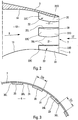
- the turbofan engine 1 with longitudinal axis LL and shown on the figure 1 comprises a nacelle 2 delimited externally by an outer shell of nacelle 3.
- the nacelle 2 comprises, at the front, an air inlet 4 provided with a leading edge 5 and, at the rear, an air outlet orifice 6 provided with a trailing edge 7.
- the external fan cowl 14 forms a nozzle for the cold flow and converges, towards the rear of the turbine engine 1, towards said external cowl of the pod 3, to form therewith the edge 7 of said orifice 6, which therefore constitutes the outlet port of the cold stream.
- the turbine engine 1 comprises a plurality of bosses 20 (see also FIGS. Figures 2 and 3 )
- the bosses 20 project into the annular channel of cold flow 12 and delimit between them longitudinal channels 21.
- the bosses 20 are inserts and attached to said outer cover blower 14, by any known means (not shown) such as welding, screws, etc.
- Each boss 20 has a convex face 22 forming, for the cold stream 9, a convergent 22C directed forwardly followed by a divergent 22D directed rearwardly.
- the rear portion of each diverging portion 22D is connected to the trailing edge 7 of the orifice 6.
- each boss 20 comprises two flat lateral faces 20L, longitudinal with respect to the turbine engine 1, and the convex face 22 and said lateral faces 20L give each boss 20 a section at least approximately rectangular, evolving parallel to said longitudinal axis LL.
- the flat lateral faces 20L may be radial, that is to say that their planes then pass through said longitudinal axis L-L.
- the peripheral width l20 of the bosses 20 may be equal to the peripheral width l21 of the longitudinal channels 21.
- the jets 9.21 are directed in extension of the outer fan cowl 14, while the jets 9.20 are directed in extension of the divergent 22D of the bosses 20.
- the jets 9.20 intersect faster aerodynamic flow V than jets 9.21. This results in better penetration of the cold stream 9 in the aerodynamic flow V, and therefore a better mixture of the latter with said cold stream 9. The jet noise is reduced.
- the jets 9.20 of the cold stream 9 passing on the convergent-divergent 22C-22D have, at the trailing edge 7, an acceleration much greater than that of the jets 9.21 passing in the longitudinal channels 21, between the bosses 20.
- On the figure 5 there is shown in plan a boss 20 with the external fan cowl portion 14 surrounding it, as well as hatched areas of iso acceleration of the cold stream 9 (these zones of iso acceleration are the result of tests and are of as darker as the acceleration is higher).
- FIG. 6 test results are shown on a turbine engine fitted to a long-haul aircraft.
- This figure 6 is a diagram indicating the pressure oscillations P at the rear of the turbine engine as a function of the distance d to it.
- Curve 23 in solid line of the figure 6 corresponds to said improved turbine engine according to the invention by fixing 36 equalized bosses 20 at the periphery of the outlet orifice of its external fan cowl, so as to provide as many longitudinal channels 21 of the same peripheral width as said bosses, each of these the last having a length of the order of 200 mm.
- the dashed curve 24 of the figure 6 corresponds to the same turbine engine not improved according to the invention.
Landscapes
- Engineering & Computer Science (AREA)
- Chemical & Material Sciences (AREA)
- Combustion & Propulsion (AREA)
- Mechanical Engineering (AREA)
- General Engineering & Computer Science (AREA)
- Structures Of Non-Positive Displacement Pumps (AREA)
Description
- La présente invention concerne un turbomoteur à émission de bruit réduite pour aéronef.
- On sait que, à l'arrière d'un turbomoteur à double flux monté sur un aéronef, le flux froid supersonique, en s'écoulant vers l'aval dudit turbomoteur, entre en contact avec l'écoulement aérodynamique extérieur dudit turbomoteur. Comme les vitesses dudit flux froid et dudit écoulement sont différentes l'une de l'autre, il en résulte des cisaillements fluides de pénétration entre ceux-ci, ce qui engendre du bruit, appelé "bruit de jet" dans la technique aéronautique.
- De plus, par suite d'une discontinuité de pression statique entre la pression externe et la pression à la sortie de la tuyère, ce flux froid supersonique engendre une série de cellules de compression-détente (oscillations de vitesse) agissant comme des amplificateurs de bruit et produisant un bruit dit de "cellule de choc" dans la technique aéronautique, encore appelé "shock cell noise" en langue anglaise.
- Pour atténuer le bruit émis à l'arrière d'un turbomoteur à double flux, on a déjà pensé à modifier la partie arrière de la tuyère du flux froid. Par exemple, on a déjà proposé de prolonger ladite tuyère vers l'arrière par des "chevrons" (voir par exemple
US 4 284 170 etUS 6 360 528 ) ou de conformer la partie arrière de ladite tuyère en "pétales ondulés" ( voir par exempleGB 2 160 265 US 4 786 016 etUS 6 082 635 ). - Outre le fait que ces tuyères connues exigent des conformations spéciales définitives qui, généralement, augmentent les coûts, la masse et la traînée, on doit constater que, bien qu'étant efficaces pour atténuer le bruit de jet en créant des turbulences favorisant le mélange du flux froid et de l'écoulement aérodynamique extérieur, elles ne produisent que peu d'effet dans la réduction du bruit de cellule de choc.
- Par ailleurs, le document
EP-1 703 114 décrit un turbomoteur à bruit réduit dans lequel une pluralité de bossages sont répartis à la périphérie de l'orifice de sortie du flux froid en faisant saillie dans ce dernier, chacun desdits bossages formant un convergent suivi d'un divergent raccordé au bord dudit orifice de sortie du flux froid. - L'objet de la présente invention est de perfectionner de tels bossages pour permettre non seulement une atténuation du bruit de jet, mais encore une réduction du bruit de cellule de choc.
- L'invention est définie dans les revendications adjointes.
- Grâce à la présente invention, la périphérie dudit flux froid est soumise, à la sortie de la tuyère correspondante, à une division en jets distincts d'orientations et de structures différentes, selon que lesdits jets passent sur les bossages ou dans les canaux longitudinaux se trouvant entre lesdits bossages. En effet, les jets de flux froid passant dans lesdits canaux longitudinaux ont une direction prolongeant ledit capot externe de soufflante et présentent, au bord dudit orifice de sortie du flux froid, une valeur d'accélération égale à la valeur nominale de la tuyère. En revanche, les jets de flux froid passant sur les bossages sont dirigés vers l'extérieur, en prolongement dudit divergent, et pénètrent dans l'écoulement aérodynamique autour du turbomoteur. De plus, ils présentent, au bord dudit orifice de sortie du flux froid, une accélération très supérieure à ladite valeur nominale du fait d'une détente plus grande due auxdits bossages.
- Par ailleurs, du fait de la présence desdites faces latérales planes, on engendre un fort cisaillement entre les jets de flux froid passant sur les bossages et ceux traversant lesdits canaux longitudinaux, ce qui provoque la formation de tourbillons favorisant le mélange entre l'écoulement aérodynamique extérieur et ledit flux froid. L'orientation desdites faces latérales planes peut par exemple être radiale, par rapport audit turbomoteur.
- Ainsi, lesdits bossages conformes à la présente invention :
- induisent des hétérogénéités radiales dans le champ de pression du flux froid à la sortie de la tuyère de soufflante, c'est-à-dire qu'ils désorganisent localement la structure dudit flux foid, ce qui entraîne à l'arrière du turbomoteur une réduction de l'intensité des cellules de chocs et donc de l'amplitude des oscillations de vitesse ; et, simultanément,
- favorisent le mélange entre le flux froid et l'écoulement aérodynamique autour du turbomoteur, ce qui entraîne une réduction du bruit de jet.
- Les bossages conformes à la présente invention permettent donc d'influer, à la fois, sur la turbulence (source de bruit) et sur les cellules de chocs (amplification de ce bruit).
- De préférence, lesdits bossages sont régulièrement répartis à la périphérie dudit capot externe de soufflante. Ils peuvent de plus présenter une largeur périphérique égale à celle desdits canaux longitudinaux.
- Lesdits bossages peuvent être conformés avec ledit capot externe de soufflante pour en être une partie intégrante. Toutefois, avantageusement, lesdits bossages sont des pièces rapportées et fixées audit capot externe de soufflante. Ainsi, il est possible de perfectionner selon l'invention non seulement les turbomoteurs en cours de construction, mais encore ceux antérieurement construits.
- Les figures du dessin annexé feront bien comprendre comment l'invention peut être réalisée. Sur ces figures, des références identiques désignent des éléments semblables.
- La
figure 1 représente, en coupe axiale schématique, un turbomoteur perfectionné selon la présente invention. - La
figure 2 illustre, en vue schématique partielle agrandie, la partie arrière de la tuyère de flux froid du turbomoteur de lafigure 1 . - La
figure 3 est une vue de l'arrière, schématique et partielle, de la tuyère de lafigure 2 , vue selon la flèche III desfigures 1 et2 . - La
figure 4 illustre schématiquement le processus selon lequel les bossages conformes à la présente invention améliorent le mélange de flux à la sortie de la tuyère de flux froid. - La
figure 5 illustre schématiquement le processus selon lequel les bossages conformes à la présente invention déstructurent le flux froid. - La
figure 6 est un schéma indiquant, pour un moteur connu et pour ce même moteur connu perfectionné selon l'invention, la variation de - Le turbomoteur à double flux 1, d'axe longitudinal L-L et montré sur la
figure 1 , comporte une nacelle 2 délimitée extérieurement par un capot externe de nacelle 3. - La nacelle 2 comporte, à l'avant, une entrée d'air 4 pourvue d'un bord d'attaque 5 et, à l'arrière, un orifice de sortie d'air 6 pourvu d'un bord de fuite 7.
- A l'intérieur de ladite nacelle 2, sont disposés :
- une soufflante 8 dirigée vers l'entrée d'air 4 et apte à engendrer le flux froid 9 pour le turbomoteur 1 ;
- un générateur central 10, comprenant de façon connue des compresseurs à basse et haute pression, une chambre de combustion et des turbines à basse et haute pression, et engendrant le flux chaud 11 dudit turbomoteur 1 ; et
- un canal annulaire de flux froid 12, ménagé autour dudit générateur central 10, entre un capot interne de soufflante 13 et un capot externe de soufflante 14.
- Le capot externe de soufflante 14 forme une tuyère pour le flux froid et converge, vers l'arrière du turbomoteur 1, en direction dudit capot externe de la nacelle 3, pour former avec celui-ci le bord 7 dudit orifice 6, qui constitue donc l'orifice de sortie du flux froid.
- Au voisinage dudit orifice 6 de sortie du flux froid 9, le turbomoteur 1 comporte une pluralité de bossages 20 (voir également les
figures 2 et 3 ) régulièrement répartis à la périphérie du capot externe de soufflante 14. Les bossages 20 font saillie dans le canal annulaire de flux froid 12 et délimitent entre eux des canaux longitudinaux 21. De préférence, les bossages 20 sont des pièces rapportées et fixées audit capot externe de soufflante 14, par tout moyen connu (non représenté) tel que soudure, vis, etc ... - Chaque bossage 20 présente une face convexe 22 formant, pour le flux froid 9, un convergent 22C dirigé vers l'avant suivi d'un divergent 22D dirigé vers l'arrière. De plus, la partie arrière de chaque divergent 22D est raccordée au bord de fuite 7 de l'orifice 6.
- Comme on peut le voir sur les
figures 2 et 3 , chaque bossage 20 comporte deux faces latérales planes 20L, longitudinales par rapport au turbomoteur 1, et la face convexe 22 et lesdites faces latérales 20L confèrent à chaque bossage 20 une section au moins approximativement rectangulaire, évolutive parallèlement audit axe longitudinal L-L. - Les faces latérales planes 20L peuvent être radiales, c'est-à-dire qu'alors leurs plans passent par ledit axe longitudinal L-L. De plus, la largeur périphérique ℓ20 des bossages 20 peut être égale à la largeur périphérique ℓ21 des canaux longitudinaux 21.
- Lorsque l'aéronef (non représenté) qui porte le turbomoteur 1 se déplace, un écoulement aérodynamique V s'écoule autour de la nacelle 2, au contact du capot externe de nacelle 3 (voir les
figures 1 et4 ). Par ailleurs, comme l'illustre lafigure 4 , à la périphérie du flux froid 9, des jets 9.20 de celui-ci passent sur les bossages 20, alors que d'autres jets 9.21 dudit flux froid passent entre lesdits bossages, à travers les canaux longitudinaux 21. - Bien entendu, à la sortie de l'orifice de fuite 6, les jets 9.21 sont dirigés en prolongement du capot externe de soufflante 14, alors que les jets 9.20 sont dirigés en prolongement des divergents 22D des bossages 20. Ainsi, les jets 9.20 croisent plus rapidement l'écoulement aérodynamique V que les jets 9.21. Il en résulte une meilleure pénétration du flux froid 9 dans l'écoulement aérodynamique V, et donc un meilleur mélange de ce dernier avec ledit flux froid 9. Le bruit de jet est donc réduit.
- Par ailleurs, comme cela est illustré par la
figure 5 , les jets 9.20 du flux froid 9 passant sur les convergents-divergents 22C-22D présentent, au bord de fuite 7, une accélération très supérieure à celle des jets 9.21 passant dans les canaux longitudinaux 21, entre les bossages 20. Sur lafigure 5 , on a représenté en plan un bossage 20 avec la partie de capot externe de soufflante 14 l'entourant, ainsi que des zones hachurées d'iso accélération du flux froid 9 (ces zones d'iso accélération résultent d'essais et sont d'autant plus sombres que l'accélération est plus élevée). - De la différence des accélérations des jets 9.20 et 9.21 à la sortie de l'orifice 6, il résulte que, au moins à la périphérie, le flux froid 9 est déstructuré, de sorte que les cellules de choc de bruit sont réduites.
- Cette conséquence est illustrée par la
figure 6 . - Sur cette
figure 6 , on a représenté des résultats d'essais sur un turbomoteur équipant un avion long-courrier. Cettefigure 6 est un diagramme indiquant les oscillations de pression P à l'arrière du turbomoteur en fonction de la distance d à celui-ci. - La courbe 23 en trait plein de la
figure 6 correspond audit turbomoteur perfectionné selon l'invention en fixant 36 bossages 20 équirépartis à la périphérie de l'orifice de sortie de son capot externe de soufflante, de façon à fournir autant de canaux longitudinaux 21 de même largeur périphérique que lesdits bossages, chacun de ces derniers ayant une longueur de l'ordre de 200 mm. - En revanche la courbe 24 en pointillés de la
figure 6 correspond au même turbomoteur non perfectionné selon l'invention. - Par comparaison des courbes 23 et 24, on peut constater que la présente invention permet de réduire d'environ 20% l'amplitude de ces oscillations de pression.
Claims (4)
- Turbomoteur à double flux pour aéronef comportant, autour de son axe longitudinal (L-L):- une nacelle (2) pour vue d'un capot externe de nacelle (3) et enfermant une soufflante (8) engendrant le flux froid (9) et un générateur central (10) engendrant le flux chaud (11) ;- un canal annulaire de flux froid (12) ménagé autour dudit générateur central de flux chaud (10) ;- un: capot externe de soufflante (14) délimitant ledit canal annulaire de flux froid (12) du côté dudit capot externe de nacelle (3) ;- un orifice de sortie du flux froid (6), dont le bord (7), qui forme le bord de fuite de ladite nacelle (2), est déterminé par ledit capot externe de nacelle (3) et par tendit capot externe de souffrante (14) convergeant l'un vers l'autre jusqu'à se rejoindre; et- au voisinage dudit orifice de sortie du flux froid (6), une pluralité de bossages (20) répartis à la périphérie dudit capot externe de soufflante (14) en faisant saillie dans ledit canal annulaire de flux froid (12) en délimitant entre eux des canaux longitudinaux (21), et en formant, pour ledit flux froid (9), un convergent suivi d'un divergent raccordé au bord (7) dudit orifice de sortie du flux froid (6), chaque bossage (20) présentant une face convexe (22) formant ledit convergent (22C) et ledit divergent (22D) et deux faces latérales (20L) planes, longitudinales par rapport audit turbomoteur, ladite face convexe (22) et lesdites fasces latérales (20L) conférant audit bossage (20) une section évolutive parallèlement audit axe longitudinal (L-L), caractérisé en ce que ladite face connexe (22) et lesdites faces latérales (20L) confèrent audit brossage (20) une section au moins approximativement rectangulaire.
- Turbomoteur selon la revendication 1,
caractérisé en ce que lesdits bossages (20) sont régulièrement répartis à la périphérie dudit capot externe de soufflante (14). - Turbomoteur selon l'une des revendications 1 ou 2,
caractérisé en ce que la largeur périphérique (ℓ20) des bossages (20) est égale à la largeur périphérique (ℓ21) desdits canaux longitudinaux (21). - Turbomoteur selon l'une des revendications 1 à 3,
caractérisé en ce que lesdits bossages (20) sont des pièces rapportées et fixées audit capot externe de soufflante (14).
Applications Claiming Priority (2)
| Application Number | Priority Date | Filing Date | Title |
|---|---|---|---|
| FR0705875A FR2920035B1 (fr) | 2007-08-17 | 2007-08-17 | Turbomoteur a emission de bruit reduite pour aeronef |
| PCT/FR2008/001166 WO2009053555A1 (fr) | 2007-08-17 | 2008-08-04 | Turbomoteur à émission de bruit réduite pour aéronef |
Publications (2)
| Publication Number | Publication Date |
|---|---|
| EP2188514A1 EP2188514A1 (fr) | 2010-05-26 |
| EP2188514B1 true EP2188514B1 (fr) | 2017-04-12 |
Family
ID=39185778
Family Applications (1)
| Application Number | Title | Priority Date | Filing Date |
|---|---|---|---|
| EP08843033.5A Active EP2188514B1 (fr) | 2007-08-17 | 2008-08-04 | Turbomoteur à émission de bruit réduite pour aéronef |
Country Status (9)
| Country | Link |
|---|---|
| US (1) | US8544278B2 (fr) |
| EP (1) | EP2188514B1 (fr) |
| JP (1) | JP5023213B2 (fr) |
| CN (1) | CN101970843B (fr) |
| BR (1) | BRPI0814484A8 (fr) |
| CA (1) | CA2695626C (fr) |
| FR (1) | FR2920035B1 (fr) |
| RU (1) | RU2451814C2 (fr) |
| WO (1) | WO2009053555A1 (fr) |
Families Citing this family (7)
| Publication number | Priority date | Publication date | Assignee | Title |
|---|---|---|---|---|
| DE102012219541A1 (de) | 2012-10-25 | 2014-04-30 | Deutsches Zentrum für Luft- und Raumfahrt e.V. | Düse, Strukturelement und Verfahren zur Herstellung einer Düse |
| CN103835810B (zh) * | 2012-11-27 | 2017-02-08 | 中航商用航空发动机有限责任公司 | 一种航空发动机进气短舱的声衬装置及航空发动机 |
| CN103790733A (zh) * | 2014-01-22 | 2014-05-14 | 李竟儒 | 一种能降低喷气式飞机喷气噪声的装置 |
| CN105464838B (zh) * | 2014-09-25 | 2019-05-21 | 波音公司 | 用于被动推力导向和羽流偏转的方法和装置 |
| US10927792B2 (en) * | 2018-06-22 | 2021-02-23 | The Boeing Company | Jet noise suppressor |
| FR3095675B1 (fr) * | 2019-05-03 | 2021-04-09 | Safran Aircraft Engines | Mélangeur à flux séparés de turbomachine |
| US10815833B1 (en) | 2019-05-21 | 2020-10-27 | Marine Turbine Technologies, LLC | Exhaust baffle apparatus and method |
Family Cites Families (25)
| Publication number | Priority date | Publication date | Assignee | Title |
|---|---|---|---|---|
| US2974744A (en) * | 1961-03-14 | Silencer | ||
| US2486019A (en) * | 1943-01-11 | 1949-10-25 | Daniel And Florence Guggenheim | Jet control apparatus applicable to entrainment of fluids |
| US2956400A (en) * | 1957-06-05 | 1960-10-18 | Curtiss Wright Corp | Internal-ribbed exhaust nozzle for jet propulsion devices |
| US3161257A (en) * | 1959-05-01 | 1964-12-15 | Young Alec David | Jet pipe nozzle silencers |
| US3776363A (en) * | 1971-05-10 | 1973-12-04 | A Kuethe | Control of noise and instabilities in jet engines, compressors, turbines, heat exchangers and the like |
| US4284170A (en) | 1979-10-22 | 1981-08-18 | United Technologies Corporation | Gas turbine noise suppressor |
| US4354648A (en) * | 1980-02-06 | 1982-10-19 | Gates Learjet Corporation | Airstream modification device for airfoils |
| GB2160265A (en) | 1984-06-12 | 1985-12-18 | Rolls Royce | Turbofan exhaust mixers |
| CA1324999C (fr) | 1986-04-30 | 1993-12-07 | Walter M. Presz, Jr. | Elements a surfaces offrant une faible resistance au frottement |
| JP3192854B2 (ja) * | 1993-12-28 | 2001-07-30 | 株式会社東芝 | タービン冷却翼 |
| RU2153591C2 (ru) * | 1995-09-22 | 2000-07-27 | Открытое акционерное общество "Самарский научно-технический комплекс им. Н.Д.Кузнецова" | Плоское сопло с центральным телом |
| US6360528B1 (en) | 1997-10-31 | 2002-03-26 | General Electric Company | Chevron exhaust nozzle for a gas turbine engine |
| US6082632A (en) | 1998-08-31 | 2000-07-04 | Hunter Industries, Inc. | Co-molded split containment ring for riser retraction spring of a pop-up sprinkler |
| US6502383B1 (en) * | 2000-08-31 | 2003-01-07 | General Electric Company | Stub airfoil exhaust nozzle |
| CN2530236Y (zh) * | 2001-11-23 | 2003-01-08 | 财团法人工业技术研究院 | 一种具有肋条型涡流产生器的新型鳍片 |
| JP3962981B2 (ja) * | 2001-12-07 | 2007-08-22 | 石川島播磨重工業株式会社 | ジェット噴流用ミキサ |
| US7017331B2 (en) * | 2002-12-07 | 2006-03-28 | Anderson Jack H | Jet nozzle mixer |
| US6658839B2 (en) * | 2002-02-28 | 2003-12-09 | The Boeing Company | Convergent/divergent segmented exhaust nozzle |
| GB0226228D0 (en) * | 2002-11-09 | 2002-12-18 | Rolls Royce Plc | Suppression of part of the noise from a gas turbine engine |
| FR2855558B1 (fr) * | 2003-05-28 | 2005-07-15 | Snecma Moteurs | Tuyere de turbomachine a reduction de bruit |
| FR2863666B1 (fr) * | 2003-12-10 | 2006-03-24 | Snecma Propulsion Solide | Dispositif d'adaptation pour tuyere de moteur fusee a divergent mobile |
| GB0505246D0 (en) * | 2005-03-15 | 2005-04-20 | Rolls Royce Plc | Engine noise |
| US7607306B2 (en) * | 2005-08-03 | 2009-10-27 | General Electric Company | Infrared suppressor apparatus and method |
| FR2890696B1 (fr) * | 2005-09-12 | 2010-09-17 | Airbus France | Turbomoteur a bruit de jet attenue |
| DE102007063018A1 (de) * | 2007-12-21 | 2009-06-25 | Rolls-Royce Deutschland Ltd & Co Kg | Düse mit Leitelementen |
-
2007
- 2007-08-17 FR FR0705875A patent/FR2920035B1/fr not_active Expired - Fee Related
-
2008
- 2008-08-04 EP EP08843033.5A patent/EP2188514B1/fr active Active
- 2008-08-04 CN CN2008801037557A patent/CN101970843B/zh not_active Expired - Fee Related
- 2008-08-04 US US12/673,042 patent/US8544278B2/en active Active
- 2008-08-04 JP JP2010520607A patent/JP5023213B2/ja not_active Expired - Fee Related
- 2008-08-04 WO PCT/FR2008/001166 patent/WO2009053555A1/fr active Application Filing
- 2008-08-04 BR BRPI0814484A patent/BRPI0814484A8/pt not_active IP Right Cessation
- 2008-08-04 CA CA2695626A patent/CA2695626C/fr not_active Expired - Fee Related
- 2008-08-04 RU RU2010109892/06A patent/RU2451814C2/ru not_active IP Right Cessation
Non-Patent Citations (1)
| Title |
|---|
| None * |
Also Published As
| Publication number | Publication date |
|---|---|
| RU2451814C2 (ru) | 2012-05-27 |
| CN101970843A (zh) | 2011-02-09 |
| US20120117939A1 (en) | 2012-05-17 |
| US8544278B2 (en) | 2013-10-01 |
| EP2188514A1 (fr) | 2010-05-26 |
| BRPI0814484A2 (pt) | 2015-11-03 |
| CN101970843B (zh) | 2013-12-25 |
| BRPI0814484A8 (pt) | 2018-12-11 |
| CA2695626C (fr) | 2015-03-31 |
| FR2920035A1 (fr) | 2009-02-20 |
| CA2695626A1 (fr) | 2009-04-30 |
| WO2009053555A1 (fr) | 2009-04-30 |
| FR2920035B1 (fr) | 2013-09-06 |
| JP2010537098A (ja) | 2010-12-02 |
| JP5023213B2 (ja) | 2012-09-12 |
| RU2010109892A (ru) | 2011-09-27 |
Similar Documents
| Publication | Publication Date | Title |
|---|---|---|
| EP2188514B1 (fr) | Turbomoteur à émission de bruit réduite pour aéronef | |
| EP1934456B1 (fr) | Turbomoteur à double flux muni d'un dispositif pour atténuer le bruit de jet | |
| EP2179163B1 (fr) | Chevron pour tuyère, tuyère et turbomoteur associés | |
| EP2773557B1 (fr) | Pylone d'accrochage pour turbomachine | |
| EP3921527B1 (fr) | Entrée d'air d'une nacelle de turboréacteur d'aéronef comportant des ouvertures de ventilation d'un flux d'air chaud de dégivrage | |
| EP3921528B1 (fr) | Entrée d'air d'une nacelle de turboréacteur d'aéronef comportant des ouvertures de ventilation d'un flux d'air chaud de dégivrage | |
| CA2798679C (fr) | Dispositif pour attenuer le bruit emis par le jet d'un moteur de propulsion d'un aeronef | |
| CA2721227A1 (fr) | Turbomoteur a double flux pour aeronef a emission de bruit reduite | |
| FR2921977A1 (fr) | Turbomoteur a double flux pour aeronef | |
| EP3274578B1 (fr) | Dispositif a grilles d'ejection de microjets pour la reduction du bruit de jet d'une turbomachine | |
| WO2017109430A1 (fr) | Turbomachine à hélice à clipping inversé | |
| FR2477100A1 (fr) | Systeme d'ejection d'air de dilution de moteur a turbosoufflante | |
| WO2020161200A1 (fr) | Entree d'air d'une nacelle de turboreacteur d'aeronef comportant des ouvertures de ventilation d'un flux d'air chaud de degivrage | |
| FR3080837A1 (fr) | Aeronef avec un module propulsif a helices non carenees agence a l'arriere d'un fuselage | |
| FR3034142A1 (fr) | Dispositif a grilles d'ejection de microjets pour la reduction du bruit de jet d'une turbomachine | |
| FR3025255A1 (fr) | Tuyere d'echappement de gaz de turbomoteur | |
| FR3034141A1 (fr) | Dispositif a microjets pour la reduction du bruit de jet d'une turbomachine | |
| FR2967134A1 (fr) | Nacelle de turbo reacteur comportant des moyens de reduction de bruit |
Legal Events
| Date | Code | Title | Description |
|---|---|---|---|
| PUAI | Public reference made under article 153(3) epc to a published international application that has entered the european phase |
Free format text: ORIGINAL CODE: 0009012 |
|
| 17P | Request for examination filed |
Effective date: 20100218 |
|
| AK | Designated contracting states |
Kind code of ref document: A1 Designated state(s): AT BE BG CH CY CZ DE DK EE ES FI FR GB GR HR HU IE IS IT LI LT LU LV MC MT NL NO PL PT RO SE SI SK TR |
|
| AX | Request for extension of the european patent |
Extension state: AL BA MK RS |
|
| 17Q | First examination report despatched |
Effective date: 20100729 |
|
| DAX | Request for extension of the european patent (deleted) | ||
| GRAP | Despatch of communication of intention to grant a patent |
Free format text: ORIGINAL CODE: EPIDOSNIGR1 |
|
| INTG | Intention to grant announced |
Effective date: 20161207 |
|
| GRAS | Grant fee paid |
Free format text: ORIGINAL CODE: EPIDOSNIGR3 |
|
| GRAA | (expected) grant |
Free format text: ORIGINAL CODE: 0009210 |
|
| AK | Designated contracting states |
Kind code of ref document: B1 Designated state(s): AT BE BG CH CY CZ DE DK EE ES FI FR GB GR HR HU IE IS IT LI LT LU LV MC MT NL NO PL PT RO SE SI SK TR |
|
| REG | Reference to a national code |
Ref country code: GB Ref legal event code: FG4D Free format text: NOT ENGLISH |
|
| REG | Reference to a national code |
Ref country code: CH Ref legal event code: EP |
|
| REG | Reference to a national code |
Ref country code: IE Ref legal event code: FG4D Free format text: LANGUAGE OF EP DOCUMENT: FRENCH |
|
| REG | Reference to a national code |
Ref country code: AT Ref legal event code: REF Ref document number: 884153 Country of ref document: AT Kind code of ref document: T Effective date: 20170515 |
|
| REG | Reference to a national code |
Ref country code: DE Ref legal event code: R096 Ref document number: 602008049762 Country of ref document: DE |
|
| REG | Reference to a national code |
Ref country code: NL Ref legal event code: MP Effective date: 20170412 |
|
| REG | Reference to a national code |
Ref country code: FR Ref legal event code: PLFP Year of fee payment: 10 |
|
| REG | Reference to a national code |
Ref country code: LT Ref legal event code: MG4D |
|
| REG | Reference to a national code |
Ref country code: AT Ref legal event code: MK05 Ref document number: 884153 Country of ref document: AT Kind code of ref document: T Effective date: 20170412 |
|
| PG25 | Lapsed in a contracting state [announced via postgrant information from national office to epo] |
Ref country code: NL Free format text: LAPSE BECAUSE OF FAILURE TO SUBMIT A TRANSLATION OF THE DESCRIPTION OR TO PAY THE FEE WITHIN THE PRESCRIBED TIME-LIMIT Effective date: 20170412 |
|
| PG25 | Lapsed in a contracting state [announced via postgrant information from national office to epo] |
Ref country code: NO Free format text: LAPSE BECAUSE OF FAILURE TO SUBMIT A TRANSLATION OF THE DESCRIPTION OR TO PAY THE FEE WITHIN THE PRESCRIBED TIME-LIMIT Effective date: 20170712 Ref country code: LT Free format text: LAPSE BECAUSE OF FAILURE TO SUBMIT A TRANSLATION OF THE DESCRIPTION OR TO PAY THE FEE WITHIN THE PRESCRIBED TIME-LIMIT Effective date: 20170412 Ref country code: ES Free format text: LAPSE BECAUSE OF FAILURE TO SUBMIT A TRANSLATION OF THE DESCRIPTION OR TO PAY THE FEE WITHIN THE PRESCRIBED TIME-LIMIT Effective date: 20170412 Ref country code: AT Free format text: LAPSE BECAUSE OF FAILURE TO SUBMIT A TRANSLATION OF THE DESCRIPTION OR TO PAY THE FEE WITHIN THE PRESCRIBED TIME-LIMIT Effective date: 20170412 Ref country code: HR Free format text: LAPSE BECAUSE OF FAILURE TO SUBMIT A TRANSLATION OF THE DESCRIPTION OR TO PAY THE FEE WITHIN THE PRESCRIBED TIME-LIMIT Effective date: 20170412 Ref country code: GR Free format text: LAPSE BECAUSE OF FAILURE TO SUBMIT A TRANSLATION OF THE DESCRIPTION OR TO PAY THE FEE WITHIN THE PRESCRIBED TIME-LIMIT Effective date: 20170713 Ref country code: FI Free format text: LAPSE BECAUSE OF FAILURE TO SUBMIT A TRANSLATION OF THE DESCRIPTION OR TO PAY THE FEE WITHIN THE PRESCRIBED TIME-LIMIT Effective date: 20170412 |
|
| PG25 | Lapsed in a contracting state [announced via postgrant information from national office to epo] |
Ref country code: BG Free format text: LAPSE BECAUSE OF FAILURE TO SUBMIT A TRANSLATION OF THE DESCRIPTION OR TO PAY THE FEE WITHIN THE PRESCRIBED TIME-LIMIT Effective date: 20170712 Ref country code: LV Free format text: LAPSE BECAUSE OF FAILURE TO SUBMIT A TRANSLATION OF THE DESCRIPTION OR TO PAY THE FEE WITHIN THE PRESCRIBED TIME-LIMIT Effective date: 20170412 Ref country code: PL Free format text: LAPSE BECAUSE OF FAILURE TO SUBMIT A TRANSLATION OF THE DESCRIPTION OR TO PAY THE FEE WITHIN THE PRESCRIBED TIME-LIMIT Effective date: 20170412 Ref country code: SE Free format text: LAPSE BECAUSE OF FAILURE TO SUBMIT A TRANSLATION OF THE DESCRIPTION OR TO PAY THE FEE WITHIN THE PRESCRIBED TIME-LIMIT Effective date: 20170412 Ref country code: IS Free format text: LAPSE BECAUSE OF FAILURE TO SUBMIT A TRANSLATION OF THE DESCRIPTION OR TO PAY THE FEE WITHIN THE PRESCRIBED TIME-LIMIT Effective date: 20170812 |
|
| REG | Reference to a national code |
Ref country code: DE Ref legal event code: R097 Ref document number: 602008049762 Country of ref document: DE |
|
| PG25 | Lapsed in a contracting state [announced via postgrant information from national office to epo] |
Ref country code: RO Free format text: LAPSE BECAUSE OF FAILURE TO SUBMIT A TRANSLATION OF THE DESCRIPTION OR TO PAY THE FEE WITHIN THE PRESCRIBED TIME-LIMIT Effective date: 20170412 Ref country code: SK Free format text: LAPSE BECAUSE OF FAILURE TO SUBMIT A TRANSLATION OF THE DESCRIPTION OR TO PAY THE FEE WITHIN THE PRESCRIBED TIME-LIMIT Effective date: 20170412 Ref country code: CZ Free format text: LAPSE BECAUSE OF FAILURE TO SUBMIT A TRANSLATION OF THE DESCRIPTION OR TO PAY THE FEE WITHIN THE PRESCRIBED TIME-LIMIT Effective date: 20170412 Ref country code: DK Free format text: LAPSE BECAUSE OF FAILURE TO SUBMIT A TRANSLATION OF THE DESCRIPTION OR TO PAY THE FEE WITHIN THE PRESCRIBED TIME-LIMIT Effective date: 20170412 Ref country code: EE Free format text: LAPSE BECAUSE OF FAILURE TO SUBMIT A TRANSLATION OF THE DESCRIPTION OR TO PAY THE FEE WITHIN THE PRESCRIBED TIME-LIMIT Effective date: 20170412 |
|
| PLBE | No opposition filed within time limit |
Free format text: ORIGINAL CODE: 0009261 |
|
| STAA | Information on the status of an ep patent application or granted ep patent |
Free format text: STATUS: NO OPPOSITION FILED WITHIN TIME LIMIT |
|
| PG25 | Lapsed in a contracting state [announced via postgrant information from national office to epo] |
Ref country code: IT Free format text: LAPSE BECAUSE OF FAILURE TO SUBMIT A TRANSLATION OF THE DESCRIPTION OR TO PAY THE FEE WITHIN THE PRESCRIBED TIME-LIMIT Effective date: 20170412 |
|
| REG | Reference to a national code |
Ref country code: DE Ref legal event code: R119 Ref document number: 602008049762 Country of ref document: DE |
|
| 26N | No opposition filed |
Effective date: 20180115 |
|
| REG | Reference to a national code |
Ref country code: CH Ref legal event code: PL |
|
| PG25 | Lapsed in a contracting state [announced via postgrant information from national office to epo] |
Ref country code: MC Free format text: LAPSE BECAUSE OF FAILURE TO SUBMIT A TRANSLATION OF THE DESCRIPTION OR TO PAY THE FEE WITHIN THE PRESCRIBED TIME-LIMIT Effective date: 20170412 |
|
| PG25 | Lapsed in a contracting state [announced via postgrant information from national office to epo] |
Ref country code: LI Free format text: LAPSE BECAUSE OF NON-PAYMENT OF DUE FEES Effective date: 20170831 Ref country code: CH Free format text: LAPSE BECAUSE OF NON-PAYMENT OF DUE FEES Effective date: 20170831 |
|
| REG | Reference to a national code |
Ref country code: IE Ref legal event code: MM4A |
|
| PG25 | Lapsed in a contracting state [announced via postgrant information from national office to epo] |
Ref country code: SI Free format text: LAPSE BECAUSE OF FAILURE TO SUBMIT A TRANSLATION OF THE DESCRIPTION OR TO PAY THE FEE WITHIN THE PRESCRIBED TIME-LIMIT Effective date: 20170412 |
|
| REG | Reference to a national code |
Ref country code: BE Ref legal event code: MM Effective date: 20170831 |
|
| PG25 | Lapsed in a contracting state [announced via postgrant information from national office to epo] |
Ref country code: LU Free format text: LAPSE BECAUSE OF NON-PAYMENT OF DUE FEES Effective date: 20170804 |
|
| PG25 | Lapsed in a contracting state [announced via postgrant information from national office to epo] |
Ref country code: DE Free format text: LAPSE BECAUSE OF NON-PAYMENT OF DUE FEES Effective date: 20180301 Ref country code: IE Free format text: LAPSE BECAUSE OF NON-PAYMENT OF DUE FEES Effective date: 20170804 |
|
| REG | Reference to a national code |
Ref country code: FR Ref legal event code: PLFP Year of fee payment: 11 |
|
| PG25 | Lapsed in a contracting state [announced via postgrant information from national office to epo] |
Ref country code: BE Free format text: LAPSE BECAUSE OF NON-PAYMENT OF DUE FEES Effective date: 20170831 |
|
| PG25 | Lapsed in a contracting state [announced via postgrant information from national office to epo] |
Ref country code: MT Free format text: LAPSE BECAUSE OF FAILURE TO SUBMIT A TRANSLATION OF THE DESCRIPTION OR TO PAY THE FEE WITHIN THE PRESCRIBED TIME-LIMIT Effective date: 20170412 |
|
| PG25 | Lapsed in a contracting state [announced via postgrant information from national office to epo] |
Ref country code: HU Free format text: LAPSE BECAUSE OF FAILURE TO SUBMIT A TRANSLATION OF THE DESCRIPTION OR TO PAY THE FEE WITHIN THE PRESCRIBED TIME-LIMIT; INVALID AB INITIO Effective date: 20080804 |
|
| PG25 | Lapsed in a contracting state [announced via postgrant information from national office to epo] |
Ref country code: CY Free format text: LAPSE BECAUSE OF NON-PAYMENT OF DUE FEES Effective date: 20170412 |
|
| PG25 | Lapsed in a contracting state [announced via postgrant information from national office to epo] |
Ref country code: TR Free format text: LAPSE BECAUSE OF FAILURE TO SUBMIT A TRANSLATION OF THE DESCRIPTION OR TO PAY THE FEE WITHIN THE PRESCRIBED TIME-LIMIT Effective date: 20170412 |
|
| PG25 | Lapsed in a contracting state [announced via postgrant information from national office to epo] |
Ref country code: PT Free format text: LAPSE BECAUSE OF FAILURE TO SUBMIT A TRANSLATION OF THE DESCRIPTION OR TO PAY THE FEE WITHIN THE PRESCRIBED TIME-LIMIT Effective date: 20170412 |
|
| PGFP | Annual fee paid to national office [announced via postgrant information from national office to epo] |
Ref country code: GB Payment date: 20230822 Year of fee payment: 16 |
|
| PGFP | Annual fee paid to national office [announced via postgrant information from national office to epo] |
Ref country code: FR Payment date: 20230824 Year of fee payment: 16 |