EP2188425B1 - Bending actuator element and bending actuator module - Google Patents
Bending actuator element and bending actuator module Download PDFInfo
- Publication number
- EP2188425B1 EP2188425B1 EP08801821A EP08801821A EP2188425B1 EP 2188425 B1 EP2188425 B1 EP 2188425B1 EP 08801821 A EP08801821 A EP 08801821A EP 08801821 A EP08801821 A EP 08801821A EP 2188425 B1 EP2188425 B1 EP 2188425B1
- Authority
- EP
- European Patent Office
- Prior art keywords
- bending actuator
- protective housing
- bending transducer
- bending
- actuator element
- Prior art date
- Legal status (The legal status is an assumption and is not a legal conclusion. Google has not performed a legal analysis and makes no representation as to the accuracy of the status listed.)
- Active
Links
- 238000005452 bending Methods 0.000 title claims abstract description 229
- 230000001681 protective effect Effects 0.000 claims abstract description 104
- 239000011248 coating agent Substances 0.000 claims abstract description 23
- 238000000576 coating method Methods 0.000 claims abstract description 23
- 239000000806 elastomer Substances 0.000 claims description 13
- 229920001971 elastomer Polymers 0.000 claims description 13
- 238000009434 installation Methods 0.000 claims description 12
- 238000003780 insertion Methods 0.000 claims description 3
- 230000037431 insertion Effects 0.000 claims description 3
- 238000004026 adhesive bonding Methods 0.000 claims description 2
- 239000003292 glue Substances 0.000 claims 2
- 230000006378 damage Effects 0.000 abstract description 9
- 239000000853 adhesive Substances 0.000 description 7
- 230000001070 adhesive effect Effects 0.000 description 7
- 239000004753 textile Substances 0.000 description 6
- 230000033001 locomotion Effects 0.000 description 5
- 230000000694 effects Effects 0.000 description 4
- 238000009940 knitting Methods 0.000 description 4
- 229920000122 acrylonitrile butadiene styrene Polymers 0.000 description 3
- 230000005540 biological transmission Effects 0.000 description 3
- 239000000463 material Substances 0.000 description 3
- 230000008878 coupling Effects 0.000 description 2
- 238000010168 coupling process Methods 0.000 description 2
- 238000005859 coupling reaction Methods 0.000 description 2
- 239000000428 dust Substances 0.000 description 2
- 239000011152 fibreglass Substances 0.000 description 2
- 238000002347 injection Methods 0.000 description 2
- 239000007924 injection Substances 0.000 description 2
- 239000000314 lubricant Substances 0.000 description 2
- 238000004519 manufacturing process Methods 0.000 description 2
- 239000002245 particle Substances 0.000 description 2
- 239000004033 plastic Substances 0.000 description 2
- 229920003023 plastic Polymers 0.000 description 2
- 230000007261 regionalization Effects 0.000 description 2
- 230000035945 sensitivity Effects 0.000 description 2
- 238000009941 weaving Methods 0.000 description 2
- MTLMVEWEYZFYTH-UHFFFAOYSA-N 1,3,5-trichloro-2-phenylbenzene Chemical compound ClC1=CC(Cl)=CC(Cl)=C1C1=CC=CC=C1 MTLMVEWEYZFYTH-UHFFFAOYSA-N 0.000 description 1
- IHIDFKLAWYPTKB-UHFFFAOYSA-N 1,3-dichloro-2-(4-chlorophenyl)benzene Chemical compound C1=CC(Cl)=CC=C1C1=C(Cl)C=CC=C1Cl IHIDFKLAWYPTKB-UHFFFAOYSA-N 0.000 description 1
- RYGMFSIKBFXOCR-UHFFFAOYSA-N Copper Chemical compound [Cu] RYGMFSIKBFXOCR-UHFFFAOYSA-N 0.000 description 1
- RTAQQCXQSZGOHL-UHFFFAOYSA-N Titanium Chemical compound [Ti] RTAQQCXQSZGOHL-UHFFFAOYSA-N 0.000 description 1
- 238000005299 abrasion Methods 0.000 description 1
- 230000001133 acceleration Effects 0.000 description 1
- XECAHXYUAAWDEL-UHFFFAOYSA-N acrylonitrile butadiene styrene Chemical compound C=CC=C.C=CC#N.C=CC1=CC=CC=C1 XECAHXYUAAWDEL-UHFFFAOYSA-N 0.000 description 1
- 239000004676 acrylonitrile butadiene styrene Substances 0.000 description 1
- 230000003213 activating effect Effects 0.000 description 1
- 230000006978 adaptation Effects 0.000 description 1
- 238000013459 approach Methods 0.000 description 1
- 238000009530 blood pressure measurement Methods 0.000 description 1
- 238000006243 chemical reaction Methods 0.000 description 1
- 150000001875 compounds Chemical class 0.000 description 1
- 239000004020 conductor Substances 0.000 description 1
- 238000011109 contamination Methods 0.000 description 1
- 230000008602 contraction Effects 0.000 description 1
- 229910052802 copper Inorganic materials 0.000 description 1
- 239000010949 copper Substances 0.000 description 1
- 230000002950 deficient Effects 0.000 description 1
- 238000013461 design Methods 0.000 description 1
- 238000005553 drilling Methods 0.000 description 1
- 230000002349 favourable effect Effects 0.000 description 1
- 239000003365 glass fiber Substances 0.000 description 1
- 239000012535 impurity Substances 0.000 description 1
- 238000001746 injection moulding Methods 0.000 description 1
- 239000011810 insulating material Substances 0.000 description 1
- 239000007788 liquid Substances 0.000 description 1
- 238000005259 measurement Methods 0.000 description 1
- 230000009347 mechanical transmission Effects 0.000 description 1
- 229910052751 metal Inorganic materials 0.000 description 1
- 239000002184 metal Substances 0.000 description 1
- 239000000203 mixture Substances 0.000 description 1
- 239000011224 oxide ceramic Substances 0.000 description 1
- 229910052574 oxide ceramic Inorganic materials 0.000 description 1
- 230000035515 penetration Effects 0.000 description 1
- 230000035939 shock Effects 0.000 description 1
- 239000000243 solution Substances 0.000 description 1
- 239000010936 titanium Substances 0.000 description 1
- 229910052719 titanium Inorganic materials 0.000 description 1
- 238000012546 transfer Methods 0.000 description 1
Images

Classifications
-
- D—TEXTILES; PAPER
- D04—BRAIDING; LACE-MAKING; KNITTING; TRIMMINGS; NON-WOVEN FABRICS
- D04B—KNITTING
- D04B15/00—Details of, or auxiliary devices incorporated in, weft knitting machines, restricted to machines of this kind
- D04B15/66—Devices for determining or controlling patterns ; Programme-control arrangements
- D04B15/68—Devices for determining or controlling patterns ; Programme-control arrangements characterised by the knitting instruments used
- D04B15/78—Electrical devices
-
- H—ELECTRICITY
- H10—SEMICONDUCTOR DEVICES; ELECTRIC SOLID-STATE DEVICES NOT OTHERWISE PROVIDED FOR
- H10N—ELECTRIC SOLID-STATE DEVICES NOT OTHERWISE PROVIDED FOR
- H10N30/00—Piezoelectric or electrostrictive devices
- H10N30/20—Piezoelectric or electrostrictive devices with electrical input and mechanical output, e.g. functioning as actuators or vibrators
- H10N30/204—Piezoelectric or electrostrictive devices with electrical input and mechanical output, e.g. functioning as actuators or vibrators using bending displacement, e.g. unimorph, bimorph or multimorph cantilever or membrane benders
- H10N30/2041—Beam type
- H10N30/2042—Cantilevers, i.e. having one fixed end
-
- H—ELECTRICITY
- H10—SEMICONDUCTOR DEVICES; ELECTRIC SOLID-STATE DEVICES NOT OTHERWISE PROVIDED FOR
- H10N—ELECTRIC SOLID-STATE DEVICES NOT OTHERWISE PROVIDED FOR
- H10N30/00—Piezoelectric or electrostrictive devices
- H10N30/30—Piezoelectric or electrostrictive devices with mechanical input and electrical output, e.g. functioning as generators or sensors
- H10N30/304—Beam type
- H10N30/306—Cantilevers
-
- H—ELECTRICITY
- H10—SEMICONDUCTOR DEVICES; ELECTRIC SOLID-STATE DEVICES NOT OTHERWISE PROVIDED FOR
- H10N—ELECTRIC SOLID-STATE DEVICES NOT OTHERWISE PROVIDED FOR
- H10N30/00—Piezoelectric or electrostrictive devices
- H10N30/80—Constructional details
- H10N30/88—Mounts; Supports; Enclosures; Casings
Definitions
- the invention relates to a bending transducer element with a bending transducer, which comprises a flat support body and a piezoelectrically active coating applied thereto on at least one side.
- the invention further relates to a bending transducer module, in which a plurality of bending transducer elements is combined.
- a bending transducer as mentioned at the outset for the bending transducer element, is primarily used to utilize the indirect or reciprocal piezoelectric effect, that is to say the conversion of electrical into mechanical energy.
- a piezoelectric bending transducer is also suitable for converting mechanical energy into electrical energy.
- the direct piezoelectric effect is utilized.
- a piezoelectric bending transducer For a piezoelectric bending transducer, there are a variety of technical applications. Such applications are, for example, as a piezoelectric printhead for an ink jet printer, as a sensor for the acceleration or pressure measurement, as an actuator for passing the pattern information in a weaving, knitting or knitting machine and as a control element in a braille line in FIG a reader for the blind, in a pneumatic valve, in a writing instrument or in a non-contact surface measuring instrument. Also, a piezoelectric bending transducer can be used as a generator for providing electrical energy. Such an application is, for example, the generation of energy for a measuring electronics, which is arranged for example on moving or rotating parts, and which is so far complicated to contact by cable only.
- the piezoelectrically active coating is generally planar with electrodes, also contact surfaces called, occupied.
- electrodes also contact surfaces called, occupied.
- a conductive support body and the support body itself act as such a contact surface. If an electrical voltage is applied to the contact surfaces, this leads, depending on the polarity, to a contraction or expansion of the piezoelectric coating arranged between the contact surfaces. As a result, the entire bending transducer bends or it is deflected at a fixed fixed end of the bending transducer defined Losende.
- a bending transducer of the type mentioned is for example from the DE 195 20 796 A1 , of the DE 40 25 436 A1 or the DE 196 20 826 B1 known.
- a bending transducer module of the type mentioned above with a plurality of piezoelectric bending transducers is used to convert an electronic information signal into a mechanically scannable information signal.
- a Biewandlermodul is used with a plurality of parallel electrical bending transducers for driving the needles or the mesh-forming elements of a weaving, knitting or knitting machine.
- the information whether a stitch is formed or not is obtained via a mechanical scanning of the deflection of the corresponding piezoelectric bending transducer.
- a bending transducer module is suitable for use in a jacquard machine.
- Such a Biewandlermodul is for example from the US 3,961,501 A or the EP 0 210 790 A2 known. Also in the DE 197 06 755.7 A1 Such a bending transducer module is proposed.
- the piezoelectrically active coating consists of a piezoceramic.
- a piezoceramic allows namely on their composition on Adaptation to different requirements, which are made, for example, in terms of thermal expansion coefficient, the size of the piezoelectric effect or in terms of flexibility.
- certain oxide ceramics for example based on lead zirconate titanium, are known which have excellent properties.
- a piezoelectrically active coating and in particular a piezoceramic exhibits a high breakage sensitivity.
- care must be taken during assembly, in an exchange or generally during transport extremely carefully. Care must be taken that the bending transducer is not mechanically bent beyond a critical limit.
- a bending transducer module many bending transducers are combined in a small space; In addition, an orientation of the bending transducer when it is inserted into the module is required. Despite careful approach nevertheless leads the high breaking sensitivity when inserting and aligning the bending transducer to an undesirably high damage rate.
- the first object is achieved according to the invention by a bending transducer element with a protective housing and a bending transducer arranged therein, which comprises a flat supporting body and a piezoelectrically active coating applied thereto on at least one side, wherein the bending transducer is essentially enclosed by the protective housing and with its fixed end directly is secured in the protective housing.
- the invention is based on the consideration that damage to the piezoelectric bending transducer auftre by partially becoming necessary mechanical stresses during transport and in particular during manual assembly There is a particularly high risk of damage when inserting and aligning the bending transducer in a bending transducer module.
- the bending transducer must be fixed with its fixed end in the bending transducer module and at the same time correctly aligned with its supporting body and the loose end for proper function.
- the invention is based on the consideration that damage to the bending transducer can be avoided by a mechanical stress, if not the bending transducer as such, but a bending transducer element from a housing and a bending transducer arranged therein is transported and mounted. Because the bending transducer is essentially enclosed by the protective housing, it is protected against external mechanical influences. Further, since the bending transducer is fastened with its fixed end directly in the protective housing, when mounting the bending transducer as such also no longer needs to be aligned. Since its position is fixed relative to the protective housing, only the protective housing must be adjusted relative to the Biewandlermermodul for correct positioning of the bending transducer in a Biewandlermodul. The bending transducer itself is not mechanically or only imperceptibly loaded.
- the invention provides a bending transducer with a protective housing surrounding it to form a structural unit, namely a bending transducer element summarize.
- the protective housing protects the bending transducer arranged therein against external mechanical influences. An orientation of the bending transducer at its installation is made exclusively by an adjustment of the protective housing.
- the bending transducers arranged in the protective housing themselves are hardly or not mechanically stressed, the damage rate during installation or replacement is considerably reduced compared to the conventional mounting of the bending transducer directly on a bending transducer module. Also During transport, the bending transducer is safely protected from external influences.
- the protective housing can be designed according generous.
- the deflection of the loose end inside the housing is mechanically tapped.
- the vibration of the bending transducer can be carried out completely inside the housing.
- the bending transducer can thus be arranged completely within the protective housing.
- the bending transducer protrudes with its loose end movable from an opening of the protective housing.
- This embodiment is particularly suitable when the loose end of the bending transducer cooperates with mechanical coupling elements for transmitting the mechanical deflection.
- An exposed end can be easily coupled mechanically to other active components.
- the bending transducers used cooperate with their respective loose ends with coupling members mechanically transfer the mechanical deflection of the bending transducer ends, for example, for driving needles and optionally strengthen.
- the projecting from the protective housing loose end of the bending transducer can also be used as such to a transmission of information by a mechanical deflection.
- the protective housing at the opening on lateral stops for the loose end By these lateral stops the mechanical deflection of the loose end is limited laterally.
- a targeted electrical control of the bending transducer defined end positions for the Losende are created by the attacks, which is assigned a defined information.
- a total of three clearly defined states of the loser In a rest position, the loose end is arranged centrally in the opening of the protective housing. The other two states result from the respective stop position of the loose end on the two lateral stops.
- the protective housing itself can be made in several parts or in one piece.
- an electrically non-conductive, insulating material for the protective housing.
- This can be for example a plastic and in particular a glass fiber reinforced plastic (GRP).
- GFP glass fiber reinforced plastic
- ABS plastic that is, an acrylonitrile-butadiene-styrene.
- the housing can be produced in particular by means of injection molding. A multi-part design of the housing provides some relief in the installation of the bending transducer within the protective housing.
- a particularly favorable variant which offers both a simple production of the protective housing and a simple mounting of the bending transducer, however, consists of manufacturing the protective housing in one piece and to form an introduction of the bending transducer in its longitudinal direction for the purpose of assembly.
- the bending transducer is inserted in its longitudinal direction with the fixed end ahead in the protective housing and fixed at the fixed end. Adhesion and / or latching of housing parts after or during assembly of the bending transducer is eliminated. It must be made only a single injection molded part. Since the protective housing must allow a certain range of motion for the bending transducer arranged therein, the introduction of the bending transducer in the protective housing is a relatively simple assembly step.
- the fixed end of the bending transducer is positively fixed in the protective housing.
- the fixed end of the inserted into the housing bending transducer can be connected in a simple manner, for example, by a jamming or screwing or by locking firmly with the protective housing.
- the bending transducer is glued to the protective housing at its fixed end.
- the strength of the compound is further improved.
- the gluing of the fixed end to the protective housing can take place when the protective housing has an adhesive penetration opening at the glued spot.
- the attachment of the bending transducer in the protective housing then takes place in that the bending transducer is performed with its fixed end ahead of the splice within the protective housing, where it is already securely held for example by a corresponding terminal contact.
- the adhesive can then be introduced into the interior of the protective housing at this point, so that the stationary end adheres firmly to the protective housing. Since the adhesive must cure inside the protective housing, it is advisable to use a UV-curable adhesive. By an appropriate irradiation - possibly through the openings therethrough - a rapid and secure bonding is achieved here. On the other hand, in an oxygen-curing adhesive, the curing time may be disadvantageously increased.
- the protective housing has a number of openings separated by webs.
- This embodiment is on the one hand in terms of a material reduction of the protective housing of advantage.
- the attachment of apertures is also desirable when the bending transducer element is used in places where it comes with mechanical abrasion, dirt or dust particles and liquids, especially oil or other lubricants in touch. This is the case, for example, in the case of Biewandlermodulen, which are used to control textile machines.
- breakthroughs such materials can pass through the protective housing back to the outside, so that the functionality of the bending transducer is maintained despite appropriately polluted environment.
- the openings laterally on the protective housing that is transverse to the direction of movement of the To arrange bending transducer. By the movement of the bending transducer, the protective housing cleans itself, so to speak.
- an electrical plug contact is preferably arranged at its fixed end in the protective housing, via which an external connection to a corresponding control line is possible.
- the plug contact is formed of a conductive elastomer, are pressed against the corresponding contact points of the bending transducer in its final assembled state in the protective housing.
- the contact surfaces of the piezoelectric coating itself can be contacted directly with the electrical plug contact, that is, in particular directly with the conductive elastomer.
- conductive pads for example made of copper, are arranged on the fixed end of the carrier body to be contacted and are conductively connected to the contact surfaces or electrodes of the piezoelectrically active coating.
- the protective housing with the bending transducer fixed therein as a whole constitutes an assembly and transportable bending transducer element, it is recommended that the protective housing of an installation adjustment end provided with pins.
- the protective housing has a U-shaped receiving element as an opening / installation aid, which comprises an engagement opening for a tool.
- the tool such as a screwdriver or the like can be easily inserted into the engagement opening, which simplifies both the installation and the removal of the bending transducer element.
- a mass element is attached to the loose end of the bending transducer protruding from the protective housing.
- a mechanical vibration or vibration of the bending transducer element then leads due to the increased vibration mass to a mechanical deflection of the bending transducer.
- a voltage is generated between the electrodes of the piezoelectric coating, which can for example be tapped via the aforementioned contact and provided for power supply.
- the lateral stops of the protective housing in particular also useful because this way a too large deflection of the bending transducer and thus damage to the piezoelectric coating is reliably avoided.
- Such an embodiment of the bending transducer element is particularly suitable for use as an energy supplier for measuring electronics, which can not be contacted in a conventional manner with electrical conductors or cables.
- a measuring electronics for example, a tire sensor which is mounted on the rim of an impeller of a motor vehicle. This because of the constant rotation only consuming electrically contactable tire sensor detects, for example, the tire pressure or other state parameter and sends the measurement result by radio to the on-board electronics of the motor vehicle.
- it makes sense to position the described bending transducer element with a patch attached to the loose mass element on the impeller. Due to the constant movement and vibration of the impeller, sufficient energy is available to the tire sensor to record the measured values and send them by radio.
- the second object is achieved by a bending transducer module, which comprises a plurality of the aforementioned bending transducer elements, wherein the bending transducer elements are combined on a printed circuit board.
- the bending transducer elements are arranged parallel to each other.
- the installation of a bending transducer module in the course of a new installation or an exchange on the printed circuit board is associated with no or at most a slight mechanical load of the bending transducer. It is always the entire bending transducer element, that is basically used the protective housing with the bending transducer arranged therein. A direct mechanical contact with the bending transducer as such is certainly prevented.
- the printed circuit board has contact pins which are connected to the electrical plug contacts of the bending transducer elements.
- the assembly of the bending transducer elements on the printed circuit board further simplified considerably, since the protective housing with appropriate holes are simply placed on the contact pins for electrical contacting. If the plug contacts of the bending transducer elements are designed in the form of a conductive elastomer, the bending transducer elements are simply placed on the contact pins.
- the printed circuit board itself is designed, for example, as a plastic part, on which both the electronics and the contact pins connected thereto are arranged.
- a bending transducer module of the type described above is particularly suitable as a control module for controlling textile machines.
- the mechanical deflection of the loose ends of the bending transducers is used for information transmission, whether a loop is to be formed or not.
- Fig. 1 shows in a perspective view a bending transducer element 1, which comprises a protective housing 3 and a bending transducer 4 arranged in the protective housing 3.
- the arranged in the housing 3 bending transducer 4 has a flat support body 6, which is provided on both sides each with a piezoelectrically active coating 7.
- the bending transducer 4 is fixed with its fixed end 9 in the interior of the protective housing 3.
- At an opening 11 of the protective housing 3 projects a loose end 10 of the bending transducer 4, which is movable in the directions indicated by arrows.
- the protective housing 3 is made as a one-piece injection molded part of a glass fiber reinforced ABS plastic.
- For mounting the bending transducer 4 is starting led from the opening 11 with the fixed end 9 ahead in the interior of the protective housing 3.
- a clamping receptacle for the loose end 10 of the bending transducer 4 is formed inside. If the bending transducer 4 is fixed with its loose end 10 in this clamping receptacle, 12 adhesive is introduced into the interior of the protective housing 3 via the insertion openings, whereby the bending transducer 4 is connected with its fixed end in addition to the positive fit materially connected to the protective housing 3.
- a particularly secure and durable connection between the bending transducer 4 and the protective housing 3 is achieved.
- a plug-in contact 18 is arranged, which comprises a conductive elastomer, against which pressed in the installed state, the contact surfaces 8 of the piezoelectrically active coating 7 and thus are conductively connected.
- the protective housing 3 further comprises above and below the support body 6 of the bending transducer 4 extending continuous strips 20.
- the lateral surfaces of the protective housing 3 surrounding the bending transducer 4 are provided with webs 21 with openings 22 arranged therebetween.
- These breakthroughs occur 22 impurities such as dirt or dust particles and lubricant or the like due to the movements of the bending transducer 4, so that the functionality of the bending transducer element 1 is maintained even in environments with increased contamination load.
- pins 24 are provided on the protective housing 3 on both ends, which serve for alignment in a possible bending converter module housing. Such an orientation or positioning is further on the underside of the protective housing 3 arranged an Justagesteg 25, which engages a correspondingly shaped recess on a Biewandlermodul housing or the like.
- a receiving element 27 is further arranged, which comprises a receiving opening for a suitable tool, in particular a screwdriver. By inserting the tool in the opening of the receiving element 27, the mounted bending transducer element 1 can be easily removed and thus replaced.
- Fig. 2 is a Biewandlermodul 28 shown in its most essential parts in an exploded view.
- a plurality of bending transducer elements 1 are arranged parallel to one another.
- Each individual bending transducer module 28 carries a total of sixteen bending transducer elements 1.
- the printed circuit board assembly 30 for receiving the bending transducer elements 1, which carries an electronic circuit 32 for activating the bending transducer 4 as well as contact pins 33 for electrical contacting, can be seen.
- the illustrated bending transducer module 28 is particularly suitable for controlling the needles of a textile machine. By the respective deflection position of the loose ends 10 of the bending transducer 4 required for the textile machine for pattern formation information is passed.
- the loose ends 10 may optionally be connected to mechanical transmission means.
- the respective bending transducer elements 1 are placed as a unit with their ends facing away from the loose ends 10 on the corresponding contact pins 33 of the printed circuit board 30.
- corresponding holes for receiving the contact pins 33 are respectively introduced.
- the contact pins 33 penetrate via the holes in a conductive elastomer, whereby an electrical contact with the contact surfaces 8 of the piezoelectric bending transducer 4 is produced.
- the contact surfaces 8 are pressed against the conductive elastomers used in the rear end of the protective housing 3.
- Both the printed circuit board assembly 30 and the bending transducer elements 1 are arranged overall in a module housing 35, which is shown only schematically. From this module housing 35, for example, the electrical connection cables and supply lines, etc. led out.
- the module housing 35 is designed so that the Bieoderleretti 1 auf labden the PCB 30 engage with the protective housing 3 respectively arranged pins 24 and adjustment bars 25 in corresponding recesses, whereby a desired orientation is achieved in the final assembled state.
- This allows a particularly simple and secure installation.
- a direct mechanical load on the bending transducer 4 is not given by the complete installation of the bending transducer elements 1.
- the damage rate of bending transducers 4 during assembly of the bending transducer module 28 or when replacing defective bending transducer elements 1 by new bending transducer elements 1 is compared to the known solutions of the prior art, the bending transducer 4 as such in the bending transducer module 28 and in the corresponding module housing 35 be, is significantly reduced.
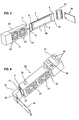
- Fig. 3 is shown in an exploded view designed as an energy supplier alternative bending transducer element 40.
- the bending transducer element 40 also has the basic components according to the bending transducer element 1 Fig. 1 on.
- the bending transducer element 40 comprises a protective housing 3, in which a bending transducer 4 is arranged.
- the in Fig. 3 Bending transducer 4 shown comprises a flat support body 6 with a piezoelectrically active coating 7 applied thereto on both sides. An outer and an inner contact surface 8 are respectively applied to the piezoelectrically active coating 7.
- the bending transducer 4 is introduced with its fixed end 9 in the direction of its longitudinal direction 41 into the protective housing 3. At the end of the protective housing 3, the fixed end 9 of the bending transducer 4 is again held with a clamping device and firmly attached to the protective housing 3 via adhesive.
- a right-angled kinked connecting element 42 is placed, on which an existing metal mass element 44 is inserted. Via the mass element 44, a vibration or vibration of the environment is converted into a deflection of the loose end 10 of the bending transducer 4. As a result of the deflection of the bending transducer 4 and the piezoelectrically active coating 7 applied thereto, a voltage is generated between the contact surfaces 8, which is picked off via a corresponding contact and provided as energy - where needed.
- the protective housing 3 In turn on both ends pins 24. These can be inserted into corresponding recesses in the mounting location, whereby the alignment of the bending transducer element 1 takes place.
- the side surfaces of the protective housing 3 of the bending transducer element 40 have through webs 21 separate openings 22.
- the bores 46 can be seen, via which an electrical contact with the contact surfaces 8 of the bending transducer 4 is made possible.
- a conductive elastomer 47 is inserted, against which the respective contact surfaces 8 of the bending transducer 4 are supported in the installed state. Via a simple plug-in contact by inserting a contact pin into the respectively conductive elastomer47 a simple electrical contacting of the bending transducer 4 is achieved with external connections.
- bending transducer element 40 is particularly suitable as an energy supplier for a measuring electronics on rotating or moving parts.
- this may be a tire sensor mounted on a rim of an impeller of a motor vehicle. With on the rim, the bending transducer element 40 is mounted. Due to the constant vibration and vibrations and rotations of the impeller, the flexural transducer element 40 generates enough energy for the tire sensor to record measured values and to transmit by radio to a corresponding on-board electronics.
Landscapes
- Engineering & Computer Science (AREA)
- Textile Engineering (AREA)
- General Electrical Machinery Utilizing Piezoelectricity, Electrostriction Or Magnetostriction (AREA)
- Electrophonic Musical Instruments (AREA)
- Piezo-Electric Transducers For Audible Bands (AREA)
Abstract
Description
Die Erfindung betrifft ein Biegewandlerelement mit einem Biegewandler, der einen flachen Tragkörper und eine darauf auf mindestens einer Seite aufgebrachte piezoelektrisch aktive Beschichtung umfasst. Die Erfindung betrifft weiter ein Biegewandlermodul, in welchem eine Mehrzahl von Biegewandlerelementen zusammengefasst ist.The invention relates to a bending transducer element with a bending transducer, which comprises a flat support body and a piezoelectrically active coating applied thereto on at least one side. The invention further relates to a bending transducer module, in which a plurality of bending transducer elements is combined.
Ein Biegewandler, wie für das Biegewandlerelement eingangs genannt, dient vorrangig zur Ausnutzung des indirekten oder reziproken piezoelektrischen Effekts, das heißt der Umwandlung von elektrischer in mechanische Energie. Gleichwohl eignet sich ein piezoelektrischer Biegewandler auch dazu, mechanische in elektrische Energie umzuwandeln. Hierbei wird der direkte piezoelektrische Effekt ausgenutzt.A bending transducer, as mentioned at the outset for the bending transducer element, is primarily used to utilize the indirect or reciprocal piezoelectric effect, that is to say the conversion of electrical into mechanical energy. However, a piezoelectric bending transducer is also suitable for converting mechanical energy into electrical energy. Here, the direct piezoelectric effect is utilized.
Für einen piezoelektrischen Biegewandler gibt es eine Vielzahl von technischen Anwendungen. Solche Anwendungen sind zum Beispiel als ein piezoelektrischer Druckkopf für einen Tintenstrahldrucker, als ein Sensor für die Beschleunigungs- oder Druckmessung, als ein Stellelement für die Weitergabe der Musterinformation in einer Web-, Wirk- oder Strickmaschine und als ein Stellelement in einer Braille-Zeile in einem Lesegerät für Blinde, in einem Pneumatikventil, in einem schreibenden Messgerät oder in einem berührungslosen Oberflächen-Messinstrument. Auch kann ein piezoelektrischer Biegewandler als Generator zur Bereitstellung elektrischer Energie eingesetzt werden. Ein solches Anwendungsgebiet ist beispielsweise die Erzeugung von Energie für eine Messelektronik, die beispielsweise auf beweglichen oder rotierenden Teilen angeordnet ist, und die insofern durch Kabel nur aufwändig kontaktierbar ist.For a piezoelectric bending transducer, there are a variety of technical applications. Such applications are, for example, as a piezoelectric printhead for an ink jet printer, as a sensor for the acceleration or pressure measurement, as an actuator for passing the pattern information in a weaving, knitting or knitting machine and as a control element in a braille line in FIG a reader for the blind, in a pneumatic valve, in a writing instrument or in a non-contact surface measuring instrument. Also, a piezoelectric bending transducer can be used as a generator for providing electrical energy. Such an application is, for example, the generation of energy for a measuring electronics, which is arranged for example on moving or rotating parts, and which is so far complicated to contact by cable only.
Zum Betrieb des genannten piezoelektrischen Biegewandlers ist die piezoelektrisch aktive Beschichtung in der Regel flächig mit Elektroden, auch Kontaktflächen genannt, belegt. Insbesondere kann im Falle eines leitfähigen Tragkörpers auch der Tragkörper selbst als eine derartige Kontaktfläche wirken. Wird eine elektrische Spannung an die Kontaktflächen angelegt, so führt dies je nach Polung zu einer Kontraktion oder einer Expansion der zwischen den Kontaktflächen angeordneten piezoelektrischen Beschichtung. Infolge dessen verbiegt sich der gesamte Biegewandler oder es wird bei einem festgehaltenen Festende des Biegewandlers das Losende definiert ausgelenkt.For operation of said piezoelectric bending transducer, the piezoelectrically active coating is generally planar with electrodes, also contact surfaces called, occupied. In particular, in the case of a conductive support body and the support body itself act as such a contact surface. If an electrical voltage is applied to the contact surfaces, this leads, depending on the polarity, to a contraction or expansion of the piezoelectric coating arranged between the contact surfaces. As a result, the entire bending transducer bends or it is deflected at a fixed fixed end of the bending transducer defined Losende.
Umgekehrt wird eine Spannung zwischen den Kontaktflächen oder Elektroden der piezoelektrischen Beschichtung erzeugt, wenn der Biegewandler durch einen mechanischen Einfluss gegenüber seiner Ruheposition verbogen wird. Dadurch wird die piezoelektrische Beschichtung kontrahiert oder ausgedehnt, wodurch sich aufgrund des direkten piezoelektrischen Effekts eine Spannung aufbaut.Conversely, a stress is generated between the contact surfaces or electrodes of the piezoelectric coating when the bending transducer is bent by a mechanical influence against its rest position. As a result, the piezoelectric coating is contracted or expanded, whereby a voltage builds up due to the direct piezoelectric effect.
Ein Biegewandler der genannten Art ist beispielsweise aus der
Ein Biegewandlermodul der eingangs genannten Art mit einer Mehrzahl von piezoelektrischen Biegewandlern wird dazu verwendet, ein elektronisches Informationssignal in ein mechanisch abtastbares Informationssignal umzuwandeln. Beispielsweise wird ein Biegewandlermodul mit einer Vielzahl von parallel angeordneten elektrischen Biegewandlern zum Ansteuern der Nadeln oder der Maschen bildenden Elemente einer Web-, Wirk- oder Strickmaschine verwendet. Zur Musterbildung in der von einer Textilmaschine erzeugten Ware wird dabei die Information, ob eine Masche gebildet wird oder nicht, über eine mechanische Abtastung der Auslenkung des entsprechenden piezoelektrischen Biegewandlers erhalten. Insbesondere eignet sich ein solches Biegewandlermodul für den Einsatz in einer Jacquard-Maschine. Ein solches Biegewandlermodul ist beispielsweise aus der
Die piezoelektrisch aktive Beschichtung besteht in der Regel aus einer Piezokeramik. Eine Piezokeramik erlaubt nämlich über ihre Zusammensetzung eine An passung an unterschiedliche Anforderungen, welche beispielsweise hinsichtlich des Wärmeausdehnungkoeffizienten, der Größe des piezoelektrischen Effekts oder aber auch hinsichtlich der Flexibilität gestellt werden. Insbesondere sind bestimmte Oxidkeramiken, zum Beispiel auf der Basis Blei-Zirkonat-Titan, bekannt, die hervorragende Eigenschaften aufweisen.As a rule, the piezoelectrically active coating consists of a piezoceramic. A piezoceramic allows namely on their composition on Adaptation to different requirements, which are made, for example, in terms of thermal expansion coefficient, the size of the piezoelectric effect or in terms of flexibility. In particular, certain oxide ceramics, for example based on lead zirconate titanium, are known which have excellent properties.
Nachteiligerweise zeigt eine piezoelektrisch aktive Beschichtung und insbesondere eine Piezokeramik eine hohe Bruchempfindlichkeit. Insbesondere bei einem Biegewandler, bei dem die piezoelektrisch aktive Beschichtung auf einem flexiblen Tragkörper aufgebracht ist, muss bei der Montage, bei einem Austausch oder generell beim Transport äußerst sorgfältig vorgegangen werden. Es muss darauf geachtet werden, dass der Biegewandler mechanisch nicht über eine kritische Grenze hinaus verbogen wird. In einem Biegewandlermodul sind zudem viele Biegewandler auf kleinem Raum zusammengefasst; zusätzlich ist eine Ausrichtung des Biegewandlers bei dessen Einsetzen in das Modul erforderlich. Trotz sorgfältigen Vorgehens führt dennoch die hohe Bruchempfindlichkeit beim Einsetzen und Ausrichten der Biegewandler zu einer unerwünscht hohen Beschädigungsquote.Disadvantageously, a piezoelectrically active coating and in particular a piezoceramic exhibits a high breakage sensitivity. In particular, in a bending transducer in which the piezoelectrically active coating is applied to a flexible support body, care must be taken during assembly, in an exchange or generally during transport extremely carefully. Care must be taken that the bending transducer is not mechanically bent beyond a critical limit. In a bending transducer module, many bending transducers are combined in a small space; In addition, an orientation of the bending transducer when it is inserted into the module is required. Despite careful approach nevertheless leads the high breaking sensitivity when inserting and aligning the bending transducer to an undesirably high damage rate.
Es ist Aufgabe der Erfindung, ein Biegewandlerelement und ein Biegewandlermodul der eingangs genannten Art anzugeben, bei welchen die Beschädigungsquote der Biegewandler bei der Montage, beim Transport oder beim Ausrichten gegenüber den bekannten Ausführungsformen des Standes der Technik herabgesetzt ist.It is an object of the invention to provide a bending transducer element and a bending transducer module of the type mentioned, in which the damage rate of the bending transducer is reduced during assembly, during transport or during alignment relative to the known embodiments of the prior art.
Die erstgenannte Aufgabe wird erfindungsgemäß gelöst durch ein Biegewandlerelement mit einem Schutzgehäuse und mit einem darin angeordneten Biegewandler, der einen flachen Tragkörper und eine darauf auf mindestens einer Seite aufgebrachte piezoelektrisch aktive Beschichtung umfasst, wobei der Biegewandler im Wesentlichen von dem Schutzgehäuse umschlossen und mit seinem Festende unmittelbar im Schutzgehäuse befestigt ist.The first object is achieved according to the invention by a bending transducer element with a protective housing and a bending transducer arranged therein, which comprises a flat supporting body and a piezoelectrically active coating applied thereto on at least one side, wherein the bending transducer is essentially enclosed by the protective housing and with its fixed end directly is secured in the protective housing.
Die Erfindung geht dabei von der Überlegung aus, dass Beschädigungen des piezoeleketrischen Biegewandlers durch teilweise notwendig werdende mechanische Belastungen beim Transport und insbesondere bei der manuellen Montage auftre ten. Eine besonders hohe Beschädigungsgefahr besteht dabei beim Einsetzen und bei der Ausrichtung des Biegewandlers in einem Biegewandlermodul. Dabei muss der Biegewandler mit seinem Festende in dem Biegewandlermodul befestigt und zugleich mit seinem Tragkörper und dem Losende für eine einwandfreie Funktion korrekt ausgerichtet werden.The invention is based on the consideration that damage to the piezoelectric bending transducer auftre by partially becoming necessary mechanical stresses during transport and in particular during manual assembly There is a particularly high risk of damage when inserting and aligning the bending transducer in a bending transducer module. In this case, the bending transducer must be fixed with its fixed end in the bending transducer module and at the same time correctly aligned with its supporting body and the loose end for proper function.
In einem weiteren Schritt geht die Erfindung von der Überlegung aus, dass eine Beschädigung des Biegewandlers durch eine mechanische Beanspruchung vermieden werden kann, wenn nicht der Biegewandler als solcher, sondern ein Biegewandlerelement aus einem Gehäuse und einem darin angeordneten Biegewandler transportiert und montiert wird. Dadurch, dass der Biegewandler im Wesentlichen von dem Schutzgehäuse umschlossen ist, ist er an sich vor äußeren mechanischen Einflüssen geschützt. Da weiter der Biegewandler mit seinem Festende unmittelbar im Schutzgehäuse befestigt ist, braucht bei einer Montage der Biegewandler als solcher auch nicht mehr ausgerichtet werden. Da seine Lage gegenüber dem Schutzgehäuse fixiert ist, muss für eine korrekte Positionierung des Biegewandlers in einem Biegewandlermodul ausschließlich das Schutzgehäuse gegenüber dem Biegewandlermodul justiert werden. Der Biegewandler selbst wird hierbei mechanisch nicht oder nur unmerklich belastet.In a further step, the invention is based on the consideration that damage to the bending transducer can be avoided by a mechanical stress, if not the bending transducer as such, but a bending transducer element from a housing and a bending transducer arranged therein is transported and mounted. Because the bending transducer is essentially enclosed by the protective housing, it is protected against external mechanical influences. Further, since the bending transducer is fastened with its fixed end directly in the protective housing, when mounting the bending transducer as such also no longer needs to be aligned. Since its position is fixed relative to the protective housing, only the protective housing must be adjusted relative to the Biewandlermermodul for correct positioning of the bending transducer in a Biewandlermodul. The bending transducer itself is not mechanically or only imperceptibly loaded.
Mit anderen Worten sieht die Erfindung vor, einen Biegewandler mit einem ihn umgebenden Schutzgehäuse zu einer Baueinheit, nämlich einem Biegewandlerelement, zusammenzufassen. Das Schutzgehäuse schützt den darin angeordneten Biegewandler vor äußeren mechanischen Einflüssen. Eine Ausrichtung des Biegewandlers an seinem Einbauort wird ausschließlich durch eine Justierung des Schutzgehäuses vorgenommen.In other words, the invention provides a bending transducer with a protective housing surrounding it to form a structural unit, namely a bending transducer element summarize. The protective housing protects the bending transducer arranged therein against external mechanical influences. An orientation of the bending transducer at its installation is made exclusively by an adjustment of the protective housing.
Da bei einer Montage oder bei einem Austausch eines Biegewandlerelements die im Schutzgehäuse angeordneten Biegewandler selbst kaum oder gar nicht mechanisch belastet werden, wird durch die Erfindung die Beschädigungsquote während des Einbaus oder Austausches gegenüber der herkömmlichen Montage der Biegewandler direkt an einem Biegewandlermodul erheblich herabgesetzt. Auch während des Transports ist der Biegewandler vor äußeren Einflüssen sicher geschützt.Since, during installation or exchange of a bending transducer element, the bending transducers arranged in the protective housing themselves are hardly or not mechanically stressed, the damage rate during installation or replacement is considerably reduced compared to the conventional mounting of the bending transducer directly on a bending transducer module. Also During transport, the bending transducer is safely protected from external influences.
Für die notwendige mechanische Bewegbarkeit des Losendes des Biegewandlers kann das Schutzgehäuse entsprechend großzügig ausgestaltet sein. Insbesondere ist es vorstellbar, dass die Auslenkung des Losendes im Inneren des Gehäuses mechanisch abgegriffen wird. Auch im Falle eines Energiegenerators kann die Schwingung des Biegewandlers vollständig im Inneren des Gehäuses erfolgen. Der Biegewandler kann insofern komplett innerhalb des Schutzgehäuses angeordnet sein.For the necessary mechanical mobility of the loose end of the bending transducer, the protective housing can be designed according generous. In particular, it is conceivable that the deflection of the loose end inside the housing is mechanically tapped. Even in the case of an energy generator, the vibration of the bending transducer can be carried out completely inside the housing. The bending transducer can thus be arranged completely within the protective housing.
In einer vorteilhaften Ausgestaltung ist es vorgesehen, dass der Biegewandler mit seinem Losende beweglich aus einer Öffnung des Schutzgehäuses hervorsteht. Diese Ausgestaltung bietet sich insbesondere an, wenn das Losende des Biegewandlers mit mechanischen Kopplungselementen zur Übertragung der mechanischen Auslenkung zusammenwirkt. Ein frei liegendes Ende kann dabei leichter an weitere Wirkkomponenten mechanisch angekoppelt werden. Dies kann beispielsweise in Biegewandlermodulen zur Steuerung von Textilmaschinen der Fall sein, wobei die eingesetzten Biegewandler mit ihren jeweiligen Losenden mit Kopplungsgliedern zusammenwirken, die die mechanische Auslenkung der Biegewandlerenden beispielsweise zur Ansteuerung von Nadeln mechanisch übertragen und gegebenenfalls verstärken. Selbstverständlich kann das aus dem Schutzgehäuse ragende Losende des Biegewandlers auch als solches zu einer Übertragung von Informationen durch eine mechanische Auslenkung benutzt werden.In an advantageous embodiment, it is provided that the bending transducer protrudes with its loose end movable from an opening of the protective housing. This embodiment is particularly suitable when the loose end of the bending transducer cooperates with mechanical coupling elements for transmitting the mechanical deflection. An exposed end can be easily coupled mechanically to other active components. This can be the case, for example, in Biewandlermodulen for the control of textile machines, the bending transducers used cooperate with their respective loose ends with coupling members mechanically transfer the mechanical deflection of the bending transducer ends, for example, for driving needles and optionally strengthen. Of course, the projecting from the protective housing loose end of the bending transducer can also be used as such to a transmission of information by a mechanical deflection.
Weiter bevorzugt weist das Schutzgehäuse an der Öffnung seitliche Anschläge für das Losende auf. Durch diese seitlichen Anschläge wird die mechanische Auslenkung des Losendes seitlich begrenzt. Im Falle einer Informationsübertragung durch die Auslenkung des Losendes, das heißt einer gezielten elektrischen Ansteuerung der Biegewandler, sind durch die Anschläge definierte Endpositionen für das Losende geschaffen, denen eine definierte Information zugeordnet ist. Für einen Biegewandler, bei dem der Tragkörper beidseitig mit einer piezoelektrisch aktiven Beschichtung versehen ist, können insgesamt drei klar definierte Zustände des Losendes erzielt werden. In einer Ruheposition ist das Losende mittig in der Öffnung des Schutzgehäuses angeordnet. Die beiden anderen Zustände ergeben sich durch die jeweilige Anschlagsposition des Losendes an den beiden seitlichen Anschlägen.Further preferably, the protective housing at the opening on lateral stops for the loose end. By these lateral stops the mechanical deflection of the loose end is limited laterally. In the case of information transmission by the deflection of the loose end, that is, a targeted electrical control of the bending transducer defined end positions for the Losende are created by the attacks, which is assigned a defined information. For a bending transducer, in which the support body is provided on both sides with a piezoelectrically active coating, a total of three clearly defined states of the loser. In a rest position, the loose end is arranged centrally in the opening of the protective housing. The other two states result from the respective stop position of the loose end on the two lateral stops.
Das Schutzgehäuse selbst kann mehrteilig oder einteilig angefertigt sein. Insbesondere ist es hierbei zweckmäßig, ein elektrisch nicht leitfähiges, isolierendes Material für das Schutzgehäuse zu verwenden. Dies kann beispielsweise ein Kunststoff und insbesondere ein glasfaserverstärkter Kunststoff (GFK) sein. Insbesondere eignet sich hierbei ein so genannter ABS-Kunststoff, das heißt ein Acryl-Nitril-Butadien-Styrol. Das Gehäuse kann insbesondere mittels Spritzguss hergestellt werden. Eine mehrteilige Ausgestaltung des Gehäuses bietet eine gewisse Erleichterung bei der Montage des Biegewandlers innerhalb des Schutzgehäuses.The protective housing itself can be made in several parts or in one piece. In particular, it is expedient to use an electrically non-conductive, insulating material for the protective housing. This can be for example a plastic and in particular a glass fiber reinforced plastic (GRP). In particular, this is a so-called ABS plastic, that is, an acrylonitrile-butadiene-styrene. The housing can be produced in particular by means of injection molding. A multi-part design of the housing provides some relief in the installation of the bending transducer within the protective housing.
In einer besonders günstigen Variante, die sowohl eine einfache Herstellung des Schutzgehäuses als auch eine einfache Montage des Biegewandlers bietet, besteht jedoch darin, das Schutzgehäuse einteilig zu fertigen und zu einer Einführung des Biegewandlers in seiner Längsrichtung zum Zwecke der Montage auszubilden. Bei der Montage wird demzufolge der Biegewandler in seiner Längsrichtung mit dem Festende voraus in das Schutzgehäuse eingeführt und am Festende fixiert. Eine Verklebung und/oder eine Verrastung von Gehäuseteilen nach oder während der Montage des Biegewandlers entfällt. Es muss lediglich ein einziges Spritzgussteil hergestellt werden. Da das Schutzgehäuse einen gewissen Bewegungsspielraum für den darin angeordneten Biegewandler erlauben muss, stellt das Einführen des Biegewandlers in das Schutzgehäuse einen relativ einfachen Montageschritt dar.In a particularly favorable variant, which offers both a simple production of the protective housing and a simple mounting of the bending transducer, however, consists of manufacturing the protective housing in one piece and to form an introduction of the bending transducer in its longitudinal direction for the purpose of assembly. During assembly, therefore, the bending transducer is inserted in its longitudinal direction with the fixed end ahead in the protective housing and fixed at the fixed end. Adhesion and / or latching of housing parts after or during assembly of the bending transducer is eliminated. It must be made only a single injection molded part. Since the protective housing must allow a certain range of motion for the bending transducer arranged therein, the introduction of the bending transducer in the protective housing is a relatively simple assembly step.
Zweckmäßigerweise ist das Festende des Biegewandlers formschlüssig im Schutzgehäuse fixiert. Bei einer solchen Ausgestaltung kann das Festende des in das Gehäuse eingeführten Biegewandlers in einfacher Art und Weise beispielsweise durch eine Verklemmung oder Verschraubung oder durch Verrastung fest mit dem Schutzgehäuse verbunden werden.Conveniently, the fixed end of the bending transducer is positively fixed in the protective housing. In such an embodiment, the fixed end of the inserted into the housing bending transducer can be connected in a simple manner, for example, by a jamming or screwing or by locking firmly with the protective housing.
Hinsichtlich der Fixierung oder Befestigung des Biegewandlers in dem Schutzgehäuse ist es weiter vorteilhaft, wenn der Biegewandler an seinem Festende mit dem Schutzgehäuse verklebt ist. Durch einen solchen Materialschluss wird die Festigkeit der Verbindung weiter verbessert. In einer einfachen Art und Weise kann die Verklebung des Festendes mit dem Schutzgehäuse dann erfolgen, wenn das Schutzgehäuse an der Klebestelle eine Eindringöffnung für Klebstoff aufweist. Insbesondere bei einem einteiligen Schutzgehäuse erfolgt die Befestigung des Biegewandlers in dem Schutzgehäuse dann dadurch, dass der Biegewandler mit seinem Festende voraus an die Klebestelle innerhalb des Schutzgehäuses geführt wird, wo es beispielsweise durch einen entsprechenden Klemmkontakt bereits sicher gehalten wird. Über geeignete Einbringöffnungen kann dann an dieser Stelle der Klebstoff in das Innere des Schutzgehäuses eingeführt werden, so dass das Festende mit dem Schutzgehäuse fest verklebt. Da der Klebstoff im Inneren des Schutzgehäuses aushärten muss, empfiehlt es sich, einen UVhärtbaren Klebstoff zu verwenden. Durch eine entsprechende Bestrahlung - gegebenenfalls durch die Öffnungen hindurch - wird hierbei eine rasche und sichere Verklebung erzielt. Bei einem durch Sauerstoff härtenden Klebstoff wäre hiergegenüber gegebenenfalls die Aushärtezeit nachteiligerweise erhöht.With regard to the fixation or attachment of the bending transducer in the protective housing, it is also advantageous if the bending transducer is glued to the protective housing at its fixed end. By such a material connection, the strength of the compound is further improved. In a simple manner, the gluing of the fixed end to the protective housing can take place when the protective housing has an adhesive penetration opening at the glued spot. In particular, in a one-piece protective housing, the attachment of the bending transducer in the protective housing then takes place in that the bending transducer is performed with its fixed end ahead of the splice within the protective housing, where it is already securely held for example by a corresponding terminal contact. By means of suitable introduction openings, the adhesive can then be introduced into the interior of the protective housing at this point, so that the stationary end adheres firmly to the protective housing. Since the adhesive must cure inside the protective housing, it is advisable to use a UV-curable adhesive. By an appropriate irradiation - possibly through the openings therethrough - a rapid and secure bonding is achieved here. On the other hand, in an oxygen-curing adhesive, the curing time may be disadvantageously increased.
In einer weiteren vorteilhaften Ausgestaltung weist das Schutzgehäuse eine Anzahl von durch Stege getrennte Durchbrüche auf. Diese Ausgestaltung ist zum einen hinsichtlich einer Materialreduzierung des Schutzgehäuses von Vorteil. Die Anbringung von Durchbrüchen ist aber auch dann wünschenswert, wenn das Biegewandlerelement an Stellen eingesetzt wird, an denen es mit mechanischem Abrieb, Schmutz oder Staubpartikeln sowie Flüssigkeiten, wie insbesondere Öl oder sonstigen Schmiermitteln in Berührung kommt. Dies ist beispielsweise im Falle von Biegewandlermodulen der Fall, die zur Steuerung von Textilmaschinen eingesetzt sind. Durch die im Schutzgehäuse angeordneten Durchbrüche können solche Materialien durch das Schutzgehäuse wieder nach außen hindurchtreten, so dass die Funktionalität des Biegewandlers trotz entsprechend verschmutzter Umgebung erhalten bleibt. Hierzu bietet es sich insbesondere an, die Durchbrüche seitlich an dem Schutzgehäuse, das heißt quer zur Bewegungsrichtung des Biegewandlers anzuordnen. Durch die Bewegung des Biegewandlers reinigt sich das Schutzgehäuse gewissermaßen von selbst.In a further advantageous embodiment, the protective housing has a number of openings separated by webs. This embodiment is on the one hand in terms of a material reduction of the protective housing of advantage. However, the attachment of apertures is also desirable when the bending transducer element is used in places where it comes with mechanical abrasion, dirt or dust particles and liquids, especially oil or other lubricants in touch. This is the case, for example, in the case of Biewandlermodulen, which are used to control textile machines. By arranged in the protective housing breakthroughs such materials can pass through the protective housing back to the outside, so that the functionality of the bending transducer is maintained despite appropriately polluted environment. For this purpose, it is particularly appropriate, the openings laterally on the protective housing, that is transverse to the direction of movement of the To arrange bending transducer. By the movement of the bending transducer, the protective housing cleans itself, so to speak.
Zur elektrischen Kontaktierung des Biegewandlers ist bevorzugterweise an seinem Festende im Schutzgehäuse ein elektrischer Steckkontakt angeordnet, über den ein externer Anschluss an eine entsprechende Steuerleitung möglich ist. In einer besonders bevorzugten Ausgestaltung ist hierbei der Steckkontakt aus einem leitfähigen Elastomer gebildet, gegen den entsprechende Kontaktstellen des Biegewandlers in seinem endmontierten Zustand im Schutzgehäuse gedrückt sind. Dabei können insbesondere die Kontaktflächen der piezoelektrischen Beschichtung selbst direkt mit dem elektrischen Steckkontakt, das heißt insbesondere direkt mit dem leitfähigen Elastomer, kontaktiert sein. Alternativ sind auf dem zu kontaktierenden Festende des Tragkörpers leitfähige Pads, beispielsweise aus Kupfer, angeordnet, die mit den Kontaktflächen oder Elektroden der piezoelektrisch aktiven Beschichtung leitend verbunden sind.For electrical contacting of the bending transducer, an electrical plug contact is preferably arranged at its fixed end in the protective housing, via which an external connection to a corresponding control line is possible. In a particularly preferred embodiment in this case the plug contact is formed of a conductive elastomer, are pressed against the corresponding contact points of the bending transducer in its final assembled state in the protective housing. In particular, the contact surfaces of the piezoelectric coating itself can be contacted directly with the electrical plug contact, that is, in particular directly with the conductive elastomer. Alternatively, conductive pads, for example made of copper, are arranged on the fixed end of the carrier body to be contacted and are conductively connected to the contact surfaces or electrodes of the piezoelectrically active coating.
Für eine externe Kontaktierungsmöglichkeit des Steckkontaktes und insbesondere des leitfähigen Elastomers sind zweckmäßigerweise im Schutzgehäuse eine Anzahl von Bohrungen eingebracht. Über diese Bohrungen können dann Kontaktstifte oder dergleichen über den Steckkontakt mit den Elektroden oder Kontaktflächen des Biegewandlers elektrisch verbunden werden. Im Falle eines leitfähigen Elastomers als Steckkontakt ist es zur Herstellung einer elektrisch leitfähigen Verbindung mit den Elektroden oder Kontaktflächen des Biegewandlers lediglich notwendig, Kontaktstifte in das Elastomer einzuführen.For an external contacting possibility of the plug contact and in particular the conductive elastomer expediently in the protective housing a number of holes are introduced. About these holes then pins or the like can be electrically connected via the plug contact with the electrodes or contact surfaces of the bending transducer. In the case of a conductive elastomer as a plug contact, it is only necessary to introduce contact pins in the elastomer for producing an electrically conductive connection with the electrodes or contact surfaces of the bending transducer.
Da das Schutzgehäuse mit dem darin fixierten Biegewandler als Ganzes ein montage- und transportfähiges Biegewandlerelement darstellt, empfiehlt es sich, das Schutzgehäuse einer Einbaujustage endseitig mit Stiften zu versehen. Mittels geeignet angebrachter Ausnehmungen an dem Gegenstück, an welchem das Biegewandlerelement zu befestigen ist, kann eine leichte Ausrichtung des Biegewandlerelements und damit des Biegewandlers erzielt werden. Zweckmäßigerweise weist das Schutzgehäuse als eine Aus-/Einbauhilfe ein U-förmiges Aufnahmeelement auf, welches eine Eingriffsöffnung für ein Werkzeug umfasst. In die Eingriffsöffnung kann leicht das Werkzeug, wie beispielsweise ein Schraubendreher oder dergleichen eingeführt werden, wodurch sich sowohl der Einbau als auch der Ausbau des Biegewandlerelements vereinfacht.Since the protective housing with the bending transducer fixed therein as a whole constitutes an assembly and transportable bending transducer element, it is recommended that the protective housing of an installation adjustment end provided with pins. By means of suitably mounted recesses on the counterpart, to which the bending transducer element is to be fastened, an easy alignment of the bending transducer element and thus of the bending transducer can be achieved. Expediently, the protective housing has a U-shaped receiving element as an opening / installation aid, which comprises an engagement opening for a tool. The tool, such as a screwdriver or the like can be easily inserted into the engagement opening, which simplifies both the installation and the removal of the bending transducer element.
In einer vorteilhaften Ausgestaltung als Energiegenerator ist an dem Losende des aus dem Schutzgehäuse ragenden Biegewandlers ein Masseelement befestigt. Eine mechanische Erschütterung oder eine Vibration des Biegewandlerelements führt dann aufgrund der vergrößerten Schwingmasse zu einer mechanischen Auslenkung des Biegewandlers. Hierdurch wird zwischen den Elektroden der piezoelektrischen Beschichtung eine Spannung erzeugt, die beispielsweise über die vorgenannte Kontaktierung abgegriffen und zur Energieversorgung bereitgestellt werden kann. Bei dieser Ausgestaltung sind die seitlichen Anschläge des Schutzgehäuses insbesondere auch deshalb sinnvoll, weil hierdurch eine zu weite Auslenkung des Biegewandlers und somit eine Beschädigung der piezoelektrischen Beschichtung sicher vermieden ist.In an advantageous embodiment as an energy generator, a mass element is attached to the loose end of the bending transducer protruding from the protective housing. A mechanical vibration or vibration of the bending transducer element then leads due to the increased vibration mass to a mechanical deflection of the bending transducer. As a result, a voltage is generated between the electrodes of the piezoelectric coating, which can for example be tapped via the aforementioned contact and provided for power supply. In this embodiment, the lateral stops of the protective housing in particular also useful because this way a too large deflection of the bending transducer and thus damage to the piezoelectric coating is reliably avoided.
Eine solche Ausgestaltung des Biegewandlerelements bietet sich insbesondere für den Einsatz als Energielieferant für eine Messelektronik an, die auf herkömmliche Weise mit elektrischen Leitern beziehungsweise Kabeln nicht kontaktiert werden kann. Eine solche Messelektronik ist beispielsweise ein Reifensensor, der auf der Felge eines Laufrads eines Kraftfahrzeugs montiert ist. Dieser aufgrund der beständigen Rotation nur aufwändig elektrisch kontaktierbare Reifensensor erfasst beispielsweise den Reifendruck oder einen sonstigen Zustandsparameter und sendet das Messergebnis per Funk an die Bordelektronik des Kraftfahrzeugs. Zur elektrischen Versorgung eines solchen Reifensensors bietet es sich an, das geschilderte Biegewandlerelement mit einem dem Losende aufgesetzten Masseelement mit auf dem Laufrad zu positionieren. Durch die beständige Bewegung und Erschütterung des Laufrads steht für den Reifensensor ausreichend Energie zur Aufnahme der Messwerte und zur Absendung per Funk zur Verfügung.Such an embodiment of the bending transducer element is particularly suitable for use as an energy supplier for measuring electronics, which can not be contacted in a conventional manner with electrical conductors or cables. Such a measuring electronics, for example, a tire sensor which is mounted on the rim of an impeller of a motor vehicle. This because of the constant rotation only consuming electrically contactable tire sensor detects, for example, the tire pressure or other state parameter and sends the measurement result by radio to the on-board electronics of the motor vehicle. For the electrical supply of such a tire sensor, it makes sense to position the described bending transducer element with a patch attached to the loose mass element on the impeller. Due to the constant movement and vibration of the impeller, sufficient energy is available to the tire sensor to record the measured values and send them by radio.
Die zweitgenannte Aufgabe wird erfindungsgemäß durch ein Biegewandlermodul gelöst, welches eine Mehrzahl der vorgenannten Biegewandlerelemente umfasst, wobei die Biegewandlerelemente an einer Flachbaugruppe zusammengefasst sind. Insbesondere sind dabei die Biegewandlerelemente parallel nebeneinander angeordnet.The second object is achieved by a bending transducer module, which comprises a plurality of the aforementioned bending transducer elements, wherein the bending transducer elements are combined on a printed circuit board. In particular, the bending transducer elements are arranged parallel to each other.
Wie bereits erwähnt ist der Einbau eines Biegewandlermoduls im Zuge einer Neumontage oder eines Austauschs an der Flachbaugruppe mit keiner oder allenfalls einer geringen mechanischen Belastung des Biegewandlers verbunden. Es wird stets das gesamte Biegewandlerelement, das heißt im Grunde genommen das Schutzgehäuse mit dem darin angeordneten Biegewandler eingesetzt. Ein direkter mechanischer Kontakt mit dem Biegewandler als solchem ist dabei sicher verhindert.As already mentioned, the installation of a bending transducer module in the course of a new installation or an exchange on the printed circuit board is associated with no or at most a slight mechanical load of the bending transducer. It is always the entire bending transducer element, that is basically used the protective housing with the bending transducer arranged therein. A direct mechanical contact with the bending transducer as such is certainly prevented.
In einer bevorzugten Ausgestaltung des Biegewandlermoduls weist die Flachbaugruppe Kontaktstifte auf, die mit den elektrischen Steckkontakten der Biegewandlerelemente in Verbindung stehen. Auf diese Weise vereinfacht sich die Montage der Biegewandlerelemente an der Flachbaugruppe weiter erheblich, da zur elektrischen Kontaktierung die Schutzgehäuse mit entsprechenden Bohrungen einfach auf die Kontaktstifte aufgesetzt werden. Sind die Steckkontakte der Biegewandlerelemente in Form eines leitfähigen Elastomers ausgestaltet, werden die Biegewandlerelemente schlichtweg einfach den Kontaktstiften aufgesetzt.In a preferred embodiment of the bending transducer module, the printed circuit board has contact pins which are connected to the electrical plug contacts of the bending transducer elements. In this way, the assembly of the bending transducer elements on the printed circuit board further simplified considerably, since the protective housing with appropriate holes are simply placed on the contact pins for electrical contacting. If the plug contacts of the bending transducer elements are designed in the form of a conductive elastomer, the bending transducer elements are simply placed on the contact pins.
Zur Montage und Ausrichtung der Biegewandlerelemente sind die am Schutzgehäuse angeordneten Stifte vorgesehen, diese Stifte wechselwirken mit entsprechenden Ausnehmungen, die in einem Modulgehäuse angeordnet sind, in welchem sowohl die Flachbaugruppe als auch die Biegewandlerelemente angeordnet sind.For mounting and aligning the bending transducer elements arranged on the protective housing pins are provided, these pins interact with corresponding recesses which are arranged in a module housing in which both the printed circuit board assembly and the bending transducer elements are arranged.
Die Flachbaugruppe selbst ist beispielsweise als ein Kunststoffteil ausgestaltet, auf welchem sowohl die Elektronik als auch die damit verbundenen Kontaktstifte angeordnet sind.The printed circuit board itself is designed, for example, as a plastic part, on which both the electronics and the contact pins connected thereto are arranged.
Ein Biegewandlermodul der vorbeschriebenen Art eignet sich insbesondere als ein Steuermodul zur Steuerung von Textilmaschinen. Dabei wird - wie bereits erwähnt - die mechanische Auslenkung der Losenden der Biegewandler zur Informationsübertragung genutzt, ob eine Masche gebildet werden soll oder nicht.A bending transducer module of the type described above is particularly suitable as a control module for controlling textile machines. Here, as already mentioned, the mechanical deflection of the loose ends of the bending transducers is used for information transmission, whether a loop is to be formed or not.
Die weiter zu dem Biegewandlerelement vorbeschriebenen Vorteile können sinngemäß auf das Biegewandlermodul, in welchem eine Mehrzahl der Biegewandlerelemente eingesetzt ist, übertragen werden.The advantages further described above with regard to the bending transducer element can be transferred analogously to the bending transducer module in which a plurality of the bending transducer elements are used.
Ausführungsbeispiele der Erfindung sind anhand einer Zeichnung näher erläutert. Dabei zeigen jeweils in perspektivischer Darstellung:
- Fig. 1
- ein Biegewandlerelement mit einem Schutzgehäuse und einem darin angeordneten Biegewandler,
- Fig. 2
- in einer Explosionsdarstellung ein Biegewandlermodul mit einer Flachbaugruppe und einer Mehrzahl von Biegewandlerelementen gemäß
Fig. 1 , - Fig. 3
- in einer Explosionsdarstellung ein weiteres Biegewandlerelement, welches als Energiegenerator ausgelegt ist, und
- Fig. 4
- das Biegewandlerelement gemäß
Fig. 3 in seinem zusammengebau- ten Zustand.
- Fig. 1
- a bending transducer element with a protective housing and a bending transducer arranged therein,
- Fig. 2
- in an exploded view of a Biewandlermodul with a printed circuit board and a plurality of Biewandlerelementen according to
Fig. 1 . - Fig. 3
- in an exploded view, another bending transducer element, which is designed as an energy generator, and
- Fig. 4
- the bending transducer element according to
Fig. 3 in its assembled condition.
Das Schutzgehäuse 3 ist als ein einstückiges Spritzgussteil aus einem glasfaserverstärkten ABS-Kunststoff gefertigt. Zur Montage wird der Biegewandler 4 ausgehend von der Öffnung 11 mit dem Festende 9 voraus in das Innere des Schutzgehäuses 3 geführt. Am Ende des Schutzgehäuses 3 ist im Inneren eine Klemmaufnahme für das Losende 10 des Biegewandlers 4 eingeformt. Ist der Biegewandler 4 mit seinem Losende 10 in dieser Klemmaufnahme fixiert, so wird über die Einbringöffnungen 12 Klebstoff in das Innere des Schutzgehäuses 3 eingebracht, wodurch der Biegewandler 4 mit seinem Festende zusätzlich zum Formschluss materialschlüssig mit dem Schutzgehäuse 3 verbunden wird. Hierdurch wird eine besonders sichere und haltbare Verbindung zwischen dem Biegewandler 4 und dem Schutzgehäuse 3 erzielt.The
An der Öffnung 11 des Schutzgehäuses 3 sind seitlich Anschläge 14 vorgesehen, wodurch zum einen eine erhöhte mechanische Belastung des Biegewandlers 4 durch eine unachtsame Auslenkung vermieden und zum anderen definierte Stellpositionen des Losendes 10 erzielt werden. Am anderen Ende des Schutzgehäuses 3 ist, hier nicht sichtbar, ein Steckkontakt 18 angeordnet, der ein leitfähiges Elastomer umfasst, gegen welches im Einbauzustand die Kontaktflächen 8 der piezoelektrisch aktiven Beschichtung 7 gedrückt und somit leitfähig verbunden sind. Über entsprechende Bohrungen in dem Schutzgehäuse 3 kann dann leicht eine elektrische Kontaktierung der Kontaktflächen 8 mit externen Anschlüssen erfolgen.At the
Das Schutzgehäuse 3 weist weiter sich oberhalb und unterhalb des Tragkörpers 6 des Biegewandlers 4 erstreckende durchgehende Leisten 20 auf. Die den Biegewandler 4 umgebenden Seitenflächen des Schutzgehäuses 3 sind durch Stege 21 mit dazwischen angeordneten Durchbrüchen 22 versehen. Über diese Durchbrüche 22 treten Verunreinigungen wie Schmutz- oder Staubpartikel sowie Schmiermittel oder dergleichen infolge der Bewegungen des Biegewandlers 4 aus, so dass die Funktionsfähigkeit des Biegewandlerelements 1 auch in Umgebungen mit erhöhter Schmutzbelastung erhalten bleibt.The
Weiter sind an dem Schutzgehäuse 3 beidendseitig Stifte 24 vorgesehen, die einer Ausrichtung in einem etwaigen Biegewandlermodul-Gehäuse dienen. Zu einer solchen Ausrichtung oder Positionierung ist weiter an der Unterseite des Schutzgehäuses 3 ein Justagesteg 25 angeordnet, der an eine entsprechend geformte Ausnehmung an einem Biegewandlermodul-Gehäuse oder dergleichen eingreift. An der Oberseite des Schutzgehäuses 3 ist ferner ein Aufnahmeelement 27 angeordnet, welches eine Aufnahmeöffnung für ein geeignetes Werkzeug, wie insbesondere einen Schraubendreher, umfasst. Durch Einführung des Werkzeugs in die Öffnung des Aufnahmeelements 27 kann das montierte Biegewandlerelement 1 leicht entfernt und somit ausgetauscht werden.Further, pins 24 are provided on the
In
Das dargestellte Biegewandlermodul 28 eignet sich insbesondere zur Ansteuerung der Nadeln einer Textilmaschine. Durch die jeweilige Auslenkposition der Losenden 10 der Biegewandler 4 wird die für die Textilmaschine zur Musterbildung erforderliche Information weitergegeben. Dabei können die Losenden 10 gegebenenfalls mit mechanischen Übertragungsmitteln verbunden sein.The illustrated
Zur elektrischen Kontaktierung werden die jeweiligen Biegewandlerelemente 1 als Einheit mit ihren den Losenden 10 abgewandten Enden auf die entsprechenden Kontaktstifte 33 der Flachbaugruppe 30 aufgesetzt. In den Schutzgehäusen 3 der Biegewandlerelemente 1 sind dabei jeweils entsprechende Bohrungen zur Aufnahme der Kontaktstifte 33 eingebracht. Die Kontaktstifte 33 dringen dabei über die Bohrungen in ein leitfähiges Elastomer ein, wodurch eine elektrische Kontaktierung mit den Kontaktflächen 8 der piezoelektrischen Biegewandler 4 hergestellt wird. Wie erwähnt sind die Kontaktflächen 8 gegen die im hinteren Ende der Schutzgehäuse 3 eingesetzten leitfähigen Elastomere gedrückt.For electrical contacting, the respective bending transducer elements 1 are placed as a unit with their ends facing away from the
Sowohl die Flachbaugruppe 30 als auch die Biegewandlerelemente 1 sind insgesamt in einem lediglich schematisch gezeigten Modulgehäuse 35 angeordnet. Aus diesem Modulgehäuse 35 sind beispielsweise die elektrischen Anschlusskabel sowie Versorgungsleitungen etc. herausgeführt.Both the printed circuit board assembly 30 and the bending transducer elements 1 are arranged overall in a
Weiter ist das Modulgehäuse 35 so gestaltet, dass die der Flachbaugruppe30 aufzusetzenden Biegewandlerelemente 1 mit den am Schutzgehäuse 3 jeweils angeordneten Stiften 24 und Justagestegen 25 in entsprechende Ausnehmungen eingreifen, wodurch eine gewünschte Ausrichtung im Montageendzustand erreicht wird. Dies ermöglicht eine besonders einfache und sichere Montage. Eine direkte mechanische Belastung der Biegewandler 4 ist durch den Kompletteinbau der Biegewandlerelemente 1 nicht gegeben. Die Beschädigungsquote von Biegewandlern 4 bei der Montage des Biegewandlermoduls 28 oder bei einem Ersatz defekter Biegewandlerelemente 1 durch neue Biegewandlerelemente 1 ist gegenüber den bekannten Lösungen des Standes der Technik, wobei die Biegewandler 4 als solche in das Biegewandlermodul 28 bzw. in das entsprechende Modulgehäuse 35 eingesetzt werden, ist deutlich herabgesetzt.Further, the
In
Zur Montage wird der Biegewandler4 mit seinem Festende 9 voran in Richtung seiner Längsrichtung 41 in das Schutzgehäuse 3 eingeführt. An dem Ende des Schutzgehäuses 3 wird das Festende 9 des Biegewandlers 4 wiederum mit einer Klemmvorrichtung gehalten und über Klebstoff fest an das Schutzgehäuse3 angebunden.For assembly, the bending
An dem aus dem Schutzgehäuse 3 wiederum herausragenden Losende 10 des Biegewandlers 4 ist ein rechtwinklig abgeknicktes Verbindungselement 42 aufgesetzt, an welchem ein aus Metall bestehendes Masseelement 44 eingesetzt ist. Über das Masseelement 44 wird eine Erschütterung oder Vibration der Umgebung in eine Auslenkung des Losendes 10 des Biegewandlers 4 umgesetzt. Infolge der Auslenkung des Biegewandlers 4 und der darauf aufgebrachten piezoelektrisch aktiven Beschichtung 7 wird eine Spannung zwischen den Kontaktflächen 8 generiert, die über eine entsprechende Kontaktierung abgegriffen und als Energie - wo benötigt - zur Verfügung gestellt wird.At the in turn protruding from the
Zur Montage und Ausrichtung des in
In
Man erkennt nun, wie an dem Losende 10 des Biegewandlers 4 mittels des Verbindungselements 42 das Masseelement 44 angeordnet ist. Um eine zu große Auslenkung des Losendes 10 aufgrund mechanischer Erschütterungen oder dergleichen zu vermeiden, sind an dem Schutzgehäuse 3 seitliche Anschläge 14 angebracht.It can now be seen how the
Auch die Seitenflächen des Schutzgehäuses 3 des Biegewandlerelements 40 weisen durch Stege 21 voneinander getrennte Durchbrüche 22 auf. Am dem Losende 10 abgewandten Ende des Schutzgehäuses 3 werden die Bohrungen 46 ersichtlich, über die eine elektrische Kontaktierung mit den Kontaktflächen 8 des Biegewandlers 4 ermöglicht ist. In diese Bohrungen 46 wird jeweils ein leitfähiges Elastomer 47 eingefügt, gegen welches sich im Einbauzustand die jeweiligen Kontaktflächen 8 des Biegewandlers4 abstützen. Über eine einfache Steckkontaktierung durch Einführen eines Kontaktstiftes in das jeweils leitfähige Elastomer47 wird eine einfache elektrische Kontaktierung des Biegewandlers 4 mit externen Anschlüssen erzielt.Also, the side surfaces of the
Das in den
- 11
- BiegewandlerelementBending transducer element
- 33
- Schutzgehäusehousing
- 44
- Biegewandlerbending transducer
- 66
- Tragkörpersupporting body
- 77
- piezoelektrisch aktive Beschichtungpiezoelectrically active coating
- 88th
- Kontaktflächecontact area
- 99
- Festendefixed end
- 1111
- Öffnungopening
- 1010
- Losendeloose end
- 1212
- Einbringöffnungeninsertion openings
- 1414
- Anschlägeattacks
- 1818
- Steckkontaktplug contact
- 2020
- LeistenAfford
- 2121
- StegeStege
- 2222
- Durchbrüchebreakthroughs
- 2424
- Stiftepencils
- 2525
- JustagestegJustagesteg
- 2727
- Aufnahmeelementreceiving element
- 2828
- BiegewandlermodulBending actuator module
- 3030
- FlachbaugruppePCB
- 3232
- Elektronikschaltungelectronic circuit
- 3333
- Kontaktstiftecontact pins
- 3535
- Modulgehäusemodule housing
- 4040
- BiegewandlerelementBending transducer element
- 4141
- Längsrichtunglongitudinal direction
- 4242
- Verbindungselementconnecting element
- 4444
- Masseelementmass element
- 4646
- Bohrungendrilling
- 4747
- Elastomerelastomer
Claims (19)
- A bending actuator element (1,40) having a bending actuator (4), comprising a flat supporting body (6) and a piezoelectrically active coating (7) applied thereon on at least one side, characterised in that the bending actuator element (1,40) has a protective housing (3) in which the bending actuator (4) is arranged, wherein the bending actuator (4) is substantially enclosed by the protective housing (3) and is secured with its fixed end (9) directly in the protective housing (3).
- A bending actuator element (1,40) according to claim 1,
characterised in that
the bending actuator (4) protrudes with its loose end (10) in a movable manner out of an opening (11) of the protective housing (3). - A bending actuator element (1,40) according to claim 1 or 2,
characterised in that
the protective housing (3) has at the opening (11) lateral stops (14) for the loose end (10). - A bending actuator element (1,40) according to one of the preceding claims,
characterised in that
the protective housing (3) is produced in one piece and is formed, for the purposes of assembly, for insertion of the bending actuator (4) in its longitudinal direction (41). - A bending actuator element (1,40) according to one of the preceding claims,
characterised in that
the fixed end (9) of the bending actuator (4) is fixed in the protective housing (3) in a form-locking manner. - A bending actuator element (1,40) according to one of the preceding claims,
characterised in that
the bending actuator (4) is glued at its fixed end (9) to the protective housing (3). - A bending actuator element (1,40) according to claim 6,
characterised in that
the protective housing (3) has at the gluing point an opening (12) for introduction of glue. - A bending actuator element (1,40) according to claim 6 or 7,
characterised in that
the bending actuator (3) is glued at its fixed end (9) by way of a UV-hardenable glue. - A bending actuator element (1,40) according to one of the preceding claims,
characterised in that
the protective housing (3) has a number of breakthroughs (22) that are separated by webs (21). - A bending actuator element (1,40) according to one of the preceding claims,
characterised in that
in order to contact the bending actuator (3) at its fixed end (9) in the protective housing (3) there is provided an electrical plug contact, formed in particular from a conductive elastomer (47). - A bending actuator element (1,40) according to claim 10,
characterised in that
the bending actuator (3) is contacted by way of a contact face directly with the electrical plug contact. - A bending actuator element (1,40) according to claim 10 or 11,
characterised in that
the protective housing (3) has a number of bores (46) for contacting the plug contact, in particular the conductive elastomer (47), with external terminals. - A bending actuator element (1,40) according to one of the preceding claims,
characterised in that
the protective housing (3) for installation-adjustment has pins (24) that are arranged on both end sides. - A bending actuator element (1,40) according to one of the preceding claims,
characterised in that
the protective housing (3) has as a removal/installation aid a U-shaped receiving element (27) with an opening for engagement of a tool. - A bending actuator element (1,40) according to one of the preceding claims,
characterised in that
secured to the loose end (9) of the bending actuator (4) there is a mass element (44). - A bending actuator module (28) comprising a plurality of bending actuator elements (1) according to one of the preceding claims, wherein the bending actuator elements (1) are combined on a flat assembly (32).
- A bending actuator module (28) according to claim 16,
characterised in that
the flat assembly (32) has contact pins (33) which communicate with the electrical plug contacts of the bending actuator elements (1). - A bending actuator module (28) according to claim 16 or 17,
characterised in that
the flat assembly (32) is fixed in a module housing (35). - A bending actuator module (28) according to claim 18,
characterised in that
the bending actuator elements (1) are each aligned in the module housing (35) by way of the pins (24) that are arranged on the protective housings (3).
Applications Claiming Priority (2)
| Application Number | Priority Date | Filing Date | Title |
|---|---|---|---|
| DE102007041636A DE102007041636A1 (en) | 2007-09-03 | 2007-09-03 | Bending transducer element and bending transducer module |
| PCT/EP2008/007193 WO2009030468A1 (en) | 2007-09-03 | 2008-09-03 | Bending actuator element and bending actuator module |
Publications (2)
| Publication Number | Publication Date |
|---|---|
| EP2188425A1 EP2188425A1 (en) | 2010-05-26 |
| EP2188425B1 true EP2188425B1 (en) | 2011-05-18 |
Family
ID=40210725
Family Applications (1)
| Application Number | Title | Priority Date | Filing Date |
|---|---|---|---|
| EP08801821A Active EP2188425B1 (en) | 2007-09-03 | 2008-09-03 | Bending actuator element and bending actuator module |
Country Status (7)
| Country | Link |
|---|---|
| EP (1) | EP2188425B1 (en) |
| JP (1) | JP5647892B2 (en) |
| KR (1) | KR101522750B1 (en) |
| CN (1) | CN101796235B (en) |
| AT (1) | ATE510055T1 (en) |
| DE (1) | DE102007041636A1 (en) |
| WO (1) | WO2009030468A1 (en) |
Families Citing this family (4)
| Publication number | Priority date | Publication date | Assignee | Title |
|---|---|---|---|---|
| ES2560011T3 (en) | 2011-02-24 | 2016-02-17 | Ceramtec Gmbh | Force module with submodules and a control and safety module for highly dynamic force generation |
| DE102011086042A1 (en) * | 2011-11-09 | 2013-05-16 | Johnson Matthey Catalysts (Germany) Gmbh | Bending transducer and micropump with a bending transducer |
| CN112305755B (en) * | 2019-07-31 | 2023-07-07 | 成都理想境界科技有限公司 | Actuator mounting structure |
| CN110629384B (en) * | 2019-10-08 | 2024-07-05 | 浙江理工大学 | Piezoelectric needle selector sensing and executing integrated state detection system |
Family Cites Families (22)
| Publication number | Priority date | Publication date | Assignee | Title |
|---|---|---|---|---|
| DE2316794A1 (en) | 1973-04-04 | 1974-10-17 | Mayer & Cie Maschinenfabrik | KNITTING MACHINE WITH PATTERN DEVICE |
| JPS6130975A (en) * | 1984-07-23 | 1986-02-13 | Nippon Telegr & Teleph Corp <Ntt> | Bimorph piezoelectric vibrator unit |
| JPS6228451A (en) | 1985-07-24 | 1987-02-06 | 渡辺靴下工業株式会社 | Needle selector for knitting machine |
| JPS62105489A (en) * | 1985-11-01 | 1987-05-15 | Nippon Telegr & Teleph Corp <Ntt> | Piezoelectric actuator unit |
| JPS63308838A (en) * | 1987-06-10 | 1988-12-16 | Matsushita Electric Ind Co Ltd | Piezoelectric relay |
| DE4025436A1 (en) | 1990-08-10 | 1992-02-13 | Siemens Ag | CONTACTING A PIEZOELECTRIC BENDING CONVERTER |
| JPH06328042A (en) * | 1993-05-27 | 1994-11-29 | Eroika Corp:Kk | Ultrasonic vibration actuator |
| JPH08246302A (en) * | 1995-03-08 | 1996-09-24 | Wac Data Service Kk | Production of finger of actuator |
| DE19520796A1 (en) | 1995-06-07 | 1996-12-12 | Siemens Ag | Piezoelectric bending transducer |
| JP3334450B2 (en) * | 1995-10-12 | 2002-10-15 | 松下電器産業株式会社 | Piezoelectric actuator and pyroelectric infrared sensor using the same |
| DE19706755A1 (en) | 1997-02-20 | 1998-08-27 | Siemens Ag | Control module for controlling the needles of a textile machine |
| JP3097645B2 (en) * | 1998-01-26 | 2000-10-10 | 日本電気株式会社 | Piezoelectric transformer |
| DE19818449A1 (en) * | 1998-04-24 | 1999-11-04 | Siemens Ag | Piezoelectric bending transducer and module from a number of piezoelectric bending transducers |
| JP2000110055A (en) * | 1998-08-06 | 2000-04-18 | Tdk Corp | Needle selector for knitting machine |
| JP2000252540A (en) * | 1999-03-01 | 2000-09-14 | Nagano Japan Radio Co | Case for storing piezoelectric element |
| DE20008844U1 (en) * | 2000-05-17 | 2000-08-17 | May, Christopher Daniel, 66133 Saarbrücken | Bracket for bending transducers, in particular solid-state bending transducers |
| JP2005160028A (en) * | 2003-10-27 | 2005-06-16 | Nec Tokin Corp | Bending vibration type actuator |
| JP4364075B2 (en) * | 2004-06-29 | 2009-11-11 | 富士通株式会社 | Moving mechanism using piezoelectric actuator and magnetic disk device having such moving mechanism |
| AT500743B8 (en) * | 2004-08-25 | 2007-02-15 | Hoerbiger Automatisierungstech | PIEZO BENDING TRAILER ARRANGEMENT AND METHOD FOR PRODUCING SUCH A PIEZO BENDING GEAR ASSEMBLY |
| JP2006116399A (en) * | 2004-10-20 | 2006-05-11 | Citizen Electronics Co Ltd | Deflection vibration type exciter |
| JP4035156B2 (en) * | 2005-12-05 | 2008-01-16 | 松下電器産業株式会社 | Ultrasonic actuator |
| JP4761459B2 (en) * | 2006-04-10 | 2011-08-31 | Necトーキン株式会社 | Piezoelectric vibration unit and piezoelectric speaker |
-
2007
- 2007-09-03 DE DE102007041636A patent/DE102007041636A1/en not_active Withdrawn
-
2008
- 2008-09-03 JP JP2010522264A patent/JP5647892B2/en active Active
- 2008-09-03 KR KR1020107007069A patent/KR101522750B1/en active IP Right Grant
- 2008-09-03 CN CN2008801053704A patent/CN101796235B/en active Active
- 2008-09-03 EP EP08801821A patent/EP2188425B1/en active Active
- 2008-09-03 WO PCT/EP2008/007193 patent/WO2009030468A1/en active Application Filing
- 2008-09-03 AT AT08801821T patent/ATE510055T1/en active
Also Published As
| Publication number | Publication date |
|---|---|
| WO2009030468A1 (en) | 2009-03-12 |
| JP5647892B2 (en) | 2015-01-07 |
| ATE510055T1 (en) | 2011-06-15 |
| CN101796235B (en) | 2012-07-25 |
| EP2188425A1 (en) | 2010-05-26 |
| CN101796235A (en) | 2010-08-04 |
| KR101522750B1 (en) | 2015-05-26 |
| KR20100061513A (en) | 2010-06-07 |
| JP2010538593A (en) | 2010-12-09 |
| DE102007041636A1 (en) | 2009-03-05 |
Similar Documents
| Publication | Publication Date | Title |
|---|---|---|
| EP2545598B1 (en) | Bending transducer | |
| EP1080503B1 (en) | Piezoelectric bending transducer and a module made of a plurality of piezoelectric bending transducers | |
| DE102008041132B4 (en) | Bending transducers for generating electrical energy from mechanical deformations | |
| EP1019972B1 (en) | Piezo-electric element | |
| EP2188425B1 (en) | Bending actuator element and bending actuator module | |
| EP2156144B1 (en) | Control device for a motor vehicle | |
| DE29623089U1 (en) | Piezoelectric element | |
| DE19523229A1 (en) | Micro-gripper for micro-assembly with substrate and microstructure body | |
| DE102008007774A1 (en) | Bending transducer for generating electrical energy from mechanical deformations | |
| DE102006025977A1 (en) | Controller for transmission system of motor vehicle, has connector part with connector contacting parts, where each contacting part is guided through wall and is formed as contact spring that lies at contact surface by spring force | |
| DE102015219851A1 (en) | control unit | |
| DE102008002680A1 (en) | Bending transducer device for generating electrical energy from deformations and circuit module | |
| EP1724849A2 (en) | Piezoelectric element | |
| DE102019102713A1 (en) | drive unit | |
| EP2592916A2 (en) | Electric control device for a motor vehicle | |
| DE102007016536B4 (en) | Device for measuring a pressure prevailing in a pressure medium | |
| DE102011085471A1 (en) | Arrangement for direct contacting of contact means and associated connection unit for a pressure measuring cell | |
| EP1835552A1 (en) | Piezoelectric device | |
| DE102018120337B3 (en) | TOUCH-SENSITIVE CONTROL FOR A MOTOR VEHICLE | |
| DE102018104886B3 (en) | Electromechanical suspension actuator | |
| WO2006084511A1 (en) | Circuit module | |
| DE102007025890B4 (en) | Control unit for a motor vehicle and arrangement of the control unit on a system interface | |
| DE102020113700B4 (en) | Piezoelectric functional network | |
| DE102010029867B4 (en) | electronic assembly | |
| EP1467432A1 (en) | Contact adapter for establishing contact with an antenna structure of a vehicle |
Legal Events
| Date | Code | Title | Description |
|---|---|---|---|
| PUAI | Public reference made under article 153(3) epc to a published international application that has entered the european phase |
Free format text: ORIGINAL CODE: 0009012 |
|
| 17P | Request for examination filed |
Effective date: 20100331 |
|
| AK | Designated contracting states |
Kind code of ref document: A1 Designated state(s): AT BE BG CH CY CZ DE DK EE ES FI FR GB GR HR HU IE IS IT LI LT LU LV MC MT NL NO PL PT RO SE SI SK TR |
|
| AX | Request for extension of the european patent |
Extension state: AL BA MK RS |
|
| GRAP | Despatch of communication of intention to grant a patent |
Free format text: ORIGINAL CODE: EPIDOSNIGR1 |
|
| DAX | Request for extension of the european patent (deleted) | ||
| GRAS | Grant fee paid |
Free format text: ORIGINAL CODE: EPIDOSNIGR3 |
|
| GRAA | (expected) grant |
Free format text: ORIGINAL CODE: 0009210 |
|
| REG | Reference to a national code |
Ref country code: GB Ref legal event code: FG4D Free format text: NOT ENGLISH |
|
| REG | Reference to a national code |
Ref country code: CH Ref legal event code: EP |
|
| REG | Reference to a national code |
Ref country code: IE Ref legal event code: FG4D Free format text: LANGUAGE OF EP DOCUMENT: GERMAN |
|
| REG | Reference to a national code |
Ref country code: DE Ref legal event code: R096 Ref document number: 502008003609 Country of ref document: DE Effective date: 20110630 |
|
| RAP2 | Party data changed (patent owner data changed or rights of a patent transferred) |
Owner name: JOHNSON MATTHEY CATALYSTS (GERMANY) GMBH |
|
| REG | Reference to a national code |
Ref country code: NL Ref legal event code: VDEP Effective date: 20110518 |
|
| PG25 | Lapsed in a contracting state [announced via postgrant information from national office to epo] |
Ref country code: LT Free format text: LAPSE BECAUSE OF FAILURE TO SUBMIT A TRANSLATION OF THE DESCRIPTION OR TO PAY THE FEE WITHIN THE PRESCRIBED TIME-LIMIT Effective date: 20110518 Ref country code: NO Free format text: LAPSE BECAUSE OF FAILURE TO SUBMIT A TRANSLATION OF THE DESCRIPTION OR TO PAY THE FEE WITHIN THE PRESCRIBED TIME-LIMIT Effective date: 20110818 Ref country code: HR Free format text: LAPSE BECAUSE OF FAILURE TO SUBMIT A TRANSLATION OF THE DESCRIPTION OR TO PAY THE FEE WITHIN THE PRESCRIBED TIME-LIMIT Effective date: 20110518 Ref country code: PT Free format text: LAPSE BECAUSE OF FAILURE TO SUBMIT A TRANSLATION OF THE DESCRIPTION OR TO PAY THE FEE WITHIN THE PRESCRIBED TIME-LIMIT Effective date: 20110919 Ref country code: SE Free format text: LAPSE BECAUSE OF FAILURE TO SUBMIT A TRANSLATION OF THE DESCRIPTION OR TO PAY THE FEE WITHIN THE PRESCRIBED TIME-LIMIT Effective date: 20110518 |
|
| PG25 | Lapsed in a contracting state [announced via postgrant information from national office to epo] |
Ref country code: LV Free format text: LAPSE BECAUSE OF FAILURE TO SUBMIT A TRANSLATION OF THE DESCRIPTION OR TO PAY THE FEE WITHIN THE PRESCRIBED TIME-LIMIT Effective date: 20110518 Ref country code: GR Free format text: LAPSE BECAUSE OF FAILURE TO SUBMIT A TRANSLATION OF THE DESCRIPTION OR TO PAY THE FEE WITHIN THE PRESCRIBED TIME-LIMIT Effective date: 20110819 Ref country code: CY Free format text: LAPSE BECAUSE OF FAILURE TO SUBMIT A TRANSLATION OF THE DESCRIPTION OR TO PAY THE FEE WITHIN THE PRESCRIBED TIME-LIMIT Effective date: 20110518 Ref country code: SI Free format text: LAPSE BECAUSE OF FAILURE TO SUBMIT A TRANSLATION OF THE DESCRIPTION OR TO PAY THE FEE WITHIN THE PRESCRIBED TIME-LIMIT Effective date: 20110518 Ref country code: IS Free format text: LAPSE BECAUSE OF FAILURE TO SUBMIT A TRANSLATION OF THE DESCRIPTION OR TO PAY THE FEE WITHIN THE PRESCRIBED TIME-LIMIT Effective date: 20110918 Ref country code: FI Free format text: LAPSE BECAUSE OF FAILURE TO SUBMIT A TRANSLATION OF THE DESCRIPTION OR TO PAY THE FEE WITHIN THE PRESCRIBED TIME-LIMIT Effective date: 20110518 Ref country code: ES Free format text: LAPSE BECAUSE OF FAILURE TO SUBMIT A TRANSLATION OF THE DESCRIPTION OR TO PAY THE FEE WITHIN THE PRESCRIBED TIME-LIMIT Effective date: 20110829 |
|
| REG | Reference to a national code |
Ref country code: IE Ref legal event code: FD4D |
|
| PG25 | Lapsed in a contracting state [announced via postgrant information from national office to epo] |
Ref country code: NL Free format text: LAPSE BECAUSE OF FAILURE TO SUBMIT A TRANSLATION OF THE DESCRIPTION OR TO PAY THE FEE WITHIN THE PRESCRIBED TIME-LIMIT Effective date: 20110518 |
|
| PG25 | Lapsed in a contracting state [announced via postgrant information from national office to epo] |
Ref country code: EE Free format text: LAPSE BECAUSE OF FAILURE TO SUBMIT A TRANSLATION OF THE DESCRIPTION OR TO PAY THE FEE WITHIN THE PRESCRIBED TIME-LIMIT Effective date: 20110518 Ref country code: IE Free format text: LAPSE BECAUSE OF FAILURE TO SUBMIT A TRANSLATION OF THE DESCRIPTION OR TO PAY THE FEE WITHIN THE PRESCRIBED TIME-LIMIT Effective date: 20110518 Ref country code: CZ Free format text: LAPSE BECAUSE OF FAILURE TO SUBMIT A TRANSLATION OF THE DESCRIPTION OR TO PAY THE FEE WITHIN THE PRESCRIBED TIME-LIMIT Effective date: 20110518 |
|
| PG25 | Lapsed in a contracting state [announced via postgrant information from national office to epo] |
Ref country code: PL Free format text: LAPSE BECAUSE OF FAILURE TO SUBMIT A TRANSLATION OF THE DESCRIPTION OR TO PAY THE FEE WITHIN THE PRESCRIBED TIME-LIMIT Effective date: 20110518 Ref country code: DK Free format text: LAPSE BECAUSE OF FAILURE TO SUBMIT A TRANSLATION OF THE DESCRIPTION OR TO PAY THE FEE WITHIN THE PRESCRIBED TIME-LIMIT Effective date: 20110518 Ref country code: RO Free format text: LAPSE BECAUSE OF FAILURE TO SUBMIT A TRANSLATION OF THE DESCRIPTION OR TO PAY THE FEE WITHIN THE PRESCRIBED TIME-LIMIT Effective date: 20110518 Ref country code: SK Free format text: LAPSE BECAUSE OF FAILURE TO SUBMIT A TRANSLATION OF THE DESCRIPTION OR TO PAY THE FEE WITHIN THE PRESCRIBED TIME-LIMIT Effective date: 20110518 |
|
| PLBE | No opposition filed within time limit |
Free format text: ORIGINAL CODE: 0009261 |
|
| STAA | Information on the status of an ep patent application or granted ep patent |
Free format text: STATUS: NO OPPOSITION FILED WITHIN TIME LIMIT |
|
| BERE | Be: lapsed |
Owner name: ARGILLON G.M.B.H. Effective date: 20110930 |
|
| 26N | No opposition filed |
Effective date: 20120221 |
|
| PG25 | Lapsed in a contracting state [announced via postgrant information from national office to epo] |
Ref country code: MC Free format text: LAPSE BECAUSE OF NON-PAYMENT OF DUE FEES Effective date: 20110930 |
|
| REG | Reference to a national code |
Ref country code: DE Ref legal event code: R097 Ref document number: 502008003609 Country of ref document: DE Effective date: 20120221 |
|
| REG | Reference to a national code |
Ref country code: FR Ref legal event code: ST Effective date: 20120531 |
|
| PG25 | Lapsed in a contracting state [announced via postgrant information from national office to epo] |
Ref country code: BE Free format text: LAPSE BECAUSE OF NON-PAYMENT OF DUE FEES Effective date: 20110930 |
|
| PG25 | Lapsed in a contracting state [announced via postgrant information from national office to epo] |
Ref country code: FR Free format text: LAPSE BECAUSE OF NON-PAYMENT OF DUE FEES Effective date: 20110930 |
|
| PG25 | Lapsed in a contracting state [announced via postgrant information from national office to epo] |
Ref country code: MT Free format text: LAPSE BECAUSE OF FAILURE TO SUBMIT A TRANSLATION OF THE DESCRIPTION OR TO PAY THE FEE WITHIN THE PRESCRIBED TIME-LIMIT Effective date: 20110518 |
|
| REG | Reference to a national code |
Ref country code: CH Ref legal event code: PL |
|
| PG25 | Lapsed in a contracting state [announced via postgrant information from national office to epo] |
Ref country code: LU Free format text: LAPSE BECAUSE OF NON-PAYMENT OF DUE FEES Effective date: 20110903 |
|
| PG25 | Lapsed in a contracting state [announced via postgrant information from national office to epo] |
Ref country code: BG Free format text: LAPSE BECAUSE OF FAILURE TO SUBMIT A TRANSLATION OF THE DESCRIPTION OR TO PAY THE FEE WITHIN THE PRESCRIBED TIME-LIMIT Effective date: 20110818 |
|
| PG25 | Lapsed in a contracting state [announced via postgrant information from national office to epo] |
Ref country code: CH Free format text: LAPSE BECAUSE OF NON-PAYMENT OF DUE FEES Effective date: 20120930 Ref country code: LI Free format text: LAPSE BECAUSE OF NON-PAYMENT OF DUE FEES Effective date: 20120930 |
|
| PG25 | Lapsed in a contracting state [announced via postgrant information from national office to epo] |
Ref country code: HU Free format text: LAPSE BECAUSE OF FAILURE TO SUBMIT A TRANSLATION OF THE DESCRIPTION OR TO PAY THE FEE WITHIN THE PRESCRIBED TIME-LIMIT Effective date: 20110518 |
|
| REG | Reference to a national code |
Ref country code: AT Ref legal event code: MM01 Ref document number: 510055 Country of ref document: AT Kind code of ref document: T Effective date: 20130903 |
|
| PG25 | Lapsed in a contracting state [announced via postgrant information from national office to epo] |
Ref country code: AT Free format text: LAPSE BECAUSE OF NON-PAYMENT OF DUE FEES Effective date: 20130903 |
|
| REG | Reference to a national code |
Ref country code: DE Ref legal event code: R081 Ref document number: 502008003609 Country of ref document: DE Owner name: JOHNSON MATTHEY PIEZO PRODUCTS GMBH, DE Free format text: FORMER OWNER: JOHNSON MATTHEY CATALYSTS (GERMANY) GMBH, 96257 REDWITZ, DE |
|
| REG | Reference to a national code |
Ref country code: GB Ref legal event code: 732E Free format text: REGISTERED BETWEEN 20220721 AND 20220727 |
|
| REG | Reference to a national code |
Ref country code: DE Ref legal event code: R082 Ref document number: 502008003609 Country of ref document: DE Representative=s name: GRAETTINGER MOEHRING VON POSCHINGER PATENTANWA, DE |
|
| PGFP | Annual fee paid to national office [announced via postgrant information from national office to epo] |
Ref country code: TR Payment date: 20230828 Year of fee payment: 16 Ref country code: GB Payment date: 20230921 Year of fee payment: 16 |
|
| PGFP | Annual fee paid to national office [announced via postgrant information from national office to epo] |
Ref country code: IT Payment date: 20230929 Year of fee payment: 16 Ref country code: DE Payment date: 20231129 Year of fee payment: 16 |