EP2188010B1 - Herzresynchronisationstherapie für patienten mit rechtsbündelblock - Google Patents
Herzresynchronisationstherapie für patienten mit rechtsbündelblock Download PDFInfo
- Publication number
- EP2188010B1 EP2188010B1 EP08796280A EP08796280A EP2188010B1 EP 2188010 B1 EP2188010 B1 EP 2188010B1 EP 08796280 A EP08796280 A EP 08796280A EP 08796280 A EP08796280 A EP 08796280A EP 2188010 B1 EP2188010 B1 EP 2188010B1
- Authority
- EP
- European Patent Office
- Prior art keywords
- interval
- pacing
- ventricular
- heart
- intervals
- Prior art date
- Legal status (The legal status is an assumption and is not a legal conclusion. Google has not performed a legal analysis and makes no representation as to the accuracy of the status listed.)
- Active
Links
Images

Classifications
-
- A—HUMAN NECESSITIES
- A61—MEDICAL OR VETERINARY SCIENCE; HYGIENE
- A61N—ELECTROTHERAPY; MAGNETOTHERAPY; RADIATION THERAPY; ULTRASOUND THERAPY
- A61N1/00—Electrotherapy; Circuits therefor
- A61N1/18—Applying electric currents by contact electrodes
- A61N1/32—Applying electric currents by contact electrodes alternating or intermittent currents
- A61N1/36—Applying electric currents by contact electrodes alternating or intermittent currents for stimulation
- A61N1/362—Heart stimulators
- A61N1/365—Heart stimulators controlled by a physiological parameter, e.g. heart potential
- A61N1/36514—Heart stimulators controlled by a physiological parameter, e.g. heart potential controlled by a physiological quantity other than heart potential, e.g. blood pressure
-
- A—HUMAN NECESSITIES
- A61—MEDICAL OR VETERINARY SCIENCE; HYGIENE
- A61B—DIAGNOSIS; SURGERY; IDENTIFICATION
- A61B7/00—Instruments for auscultation
-
- A—HUMAN NECESSITIES
- A61—MEDICAL OR VETERINARY SCIENCE; HYGIENE
- A61B—DIAGNOSIS; SURGERY; IDENTIFICATION
- A61B7/00—Instruments for auscultation
- A61B7/02—Stethoscopes
- A61B7/023—Stethoscopes for introduction into the body, e.g. into the oesophagus
-
- A—HUMAN NECESSITIES
- A61—MEDICAL OR VETERINARY SCIENCE; HYGIENE
- A61N—ELECTROTHERAPY; MAGNETOTHERAPY; RADIATION THERAPY; ULTRASOUND THERAPY
- A61N1/00—Electrotherapy; Circuits therefor
- A61N1/18—Applying electric currents by contact electrodes
- A61N1/32—Applying electric currents by contact electrodes alternating or intermittent currents
- A61N1/36—Applying electric currents by contact electrodes alternating or intermittent currents for stimulation
- A61N1/362—Heart stimulators
- A61N1/365—Heart stimulators controlled by a physiological parameter, e.g. heart potential
- A61N1/36514—Heart stimulators controlled by a physiological parameter, e.g. heart potential controlled by a physiological quantity other than heart potential, e.g. blood pressure
- A61N1/36578—Heart stimulators controlled by a physiological parameter, e.g. heart potential controlled by a physiological quantity other than heart potential, e.g. blood pressure controlled by mechanical motion of the heart wall, e.g. measured by an accelerometer or microphone
-
- A—HUMAN NECESSITIES
- A61—MEDICAL OR VETERINARY SCIENCE; HYGIENE
- A61N—ELECTROTHERAPY; MAGNETOTHERAPY; RADIATION THERAPY; ULTRASOUND THERAPY
- A61N1/00—Electrotherapy; Circuits therefor
- A61N1/18—Applying electric currents by contact electrodes
- A61N1/32—Applying electric currents by contact electrodes alternating or intermittent currents
- A61N1/36—Applying electric currents by contact electrodes alternating or intermittent currents for stimulation
- A61N1/362—Heart stimulators
- A61N1/365—Heart stimulators controlled by a physiological parameter, e.g. heart potential
- A61N1/368—Heart stimulators controlled by a physiological parameter, e.g. heart potential comprising more than one electrode co-operating with different heart regions
- A61N1/3682—Heart stimulators controlled by a physiological parameter, e.g. heart potential comprising more than one electrode co-operating with different heart regions with a variable atrioventricular delay
-
- A—HUMAN NECESSITIES
- A61—MEDICAL OR VETERINARY SCIENCE; HYGIENE
- A61N—ELECTROTHERAPY; MAGNETOTHERAPY; RADIATION THERAPY; ULTRASOUND THERAPY
- A61N1/00—Electrotherapy; Circuits therefor
- A61N1/18—Applying electric currents by contact electrodes
- A61N1/32—Applying electric currents by contact electrodes alternating or intermittent currents
- A61N1/36—Applying electric currents by contact electrodes alternating or intermittent currents for stimulation
- A61N1/362—Heart stimulators
- A61N1/365—Heart stimulators controlled by a physiological parameter, e.g. heart potential
- A61N1/368—Heart stimulators controlled by a physiological parameter, e.g. heart potential comprising more than one electrode co-operating with different heart regions
- A61N1/3684—Heart stimulators controlled by a physiological parameter, e.g. heart potential comprising more than one electrode co-operating with different heart regions for stimulating the heart at multiple sites of the ventricle or the atrium
- A61N1/36843—Bi-ventricular stimulation
Definitions
- the invention relates generally to implantable medical devices and, in particular, to a device for controlling cardiac resynchronization therapy (CRT).
- CRT cardiac resynchronization therapy
- CRT is a cardiac electrical stimulation therapy that can benefit patients suffering from heart failure by resynchronizing heart chamber contractions.
- patients can benefit from synchronization of the right and left ventricles by delivering pacing pulses in one or both chambers.
- Patients having right bundle branch block (RBBB) have normal left ventricular electrical activation with an impaired right ventricular electrical depolarization resulting in a wider QRS signal and ventricular dysynchrony.
- RBBB right bundle branch block
- a device according to the preamble of claim 1 is known from US2004/230229 .
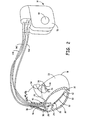
- FIG. 1 is a conceptual diagram illustrating an IMD 10 implanted in a patient 12.
- IMD 10 may take the form of a multi-chamber cardiac pacemaker as shown in FIG. 1 .
- IMD 10 is coupled to leads 14A, 14B and 14C (collectively "leads 14") that extend into the heart 16 of patient 12.
- RV lead 14A may extend through one or more veins (not shown), the superior vena cava (not shown), and right atrium 24, and into right ventricle 18.
- Left ventricular (LV) coronary sinus lead 14B may extend through the veins, the vena cava, right atrium 24, and into the coronary sinus 20 to a point adjacent to the free wall of left ventricle 22 of heart 16.
- Right atrial (RA) lead 14C extends through the veins and vena cava, and into the right atrium 24 of heart 16.
- Each of leads 14 includes electrodes (not shown), which IMD 10 may use to sense electrical signals attendant to the depolarization and repolarization of heart 16, and to provide pacing pulses to heart 16. In some embodiments, IMD 10 may also provide cardioversion or defibrillation pulses via electrodes located on leads 14. The electrodes located on leads 14 may be selected in unipolar or bipolar sensing/stimulation configurations.
- IMD 10 delivers cardiac resynchronization therapy to patient 12 via leads 14.
- IMD 10 delivers pacing pulses to right ventricle 18 via lead 14A to synchronize contractions of right ventricle 18 with contractions of left ventricle 22 resulting from intrinsic depolarizations of left ventricle 22.
- RBBB right bundle branch block
- IMD 10 may provide a more physiological interval between atrial and ventricular contractions in the sense that the interval between the atrial and ventricular contractions is a function of an intrinsic, rather than paced, depolarization of the left ventricle with the right ventricular contraction synchronized to the left ventricular contraction.
- IMD 10 may consume less power than conventional devices that provide cardiac resynchronization therapy by delivering pacing pulses to both the right ventricle 18 and left ventricle 22.
- IMD 10 determines the timing of delivery of pacing pulses to right ventricle 18 based on one or more measured cardiac event intervals corresponding to the sequence of electrical and/or mechanical events in the cardiac cycle and/or characteristics of an electrogram signal detected via one or more of leads 14 that represents electrical activity within heart 16.
- the measured intervals indicate a change in the normal temporal relation of cardiac cycle events due to the presence of RBBB.
- the first heart sound corresponding to the closure of the atrioventricular valves and the onset of ventricular systole, occurs shortly after right ventricular depolarization.
- right ventricular depolarization is delayed resulting in the first heart sound (caused by left ventricular contraction) occurring before the right ventricular depolarization.
- the normal temporal relation of the right ventricular depolarization to the occurrence of the first heart sound can be restored, thereby improving ventricular synchrony.
- the measured EGM characteristics can be used as metrics of synchrony between contractions of ventricles 18 and 22.
- wider QRS complex width indicates less synchronous contraction of ventricles 18 and 22.
- short Q-T intervals indicate increased sympathetic drive resulting from inadequate cardiac output, which in turn indicates dysynchrony of contraction of ventricles 18 and 22. Therefore, IMD 10 may, for example, select the right ventricular pace timing that results in the smallest QRS complex width, the largest Q-T interval, or the best combination of QRS complex width and Q-T interval.
- IMD 10 may be coupled to any number of leads 14 that extend to a variety of positions within or outside of heart 16.
- IMD 10 may not be coupled to a left ventricular lead 14B.
- lead 14C may extend to the left atrium of heart 16.
- Some of leads 14 may be epicardial leads.
- Some electrodes used by IMD 10 to sense electrical activity of heart 16 need not be carried by leads 14 at all, but may instead be integral with a housing of IMD 10 (not shown), or carried by subcutaneous leads extending from IMD 10.
- FIG. 2 is a conceptual diagram further illustrating IMD 10 and heart 16 of patient 12.
- leads 14 may include an elongated insulative lead body carrying a number of insulated conductors (not shown).
- bipolar electrodes 30 and 32, 34 and 36, and 38 and 40 Located adjacent distal end of leads 14A, 14B and 14C are bipolar electrodes 30 and 32, 34 and 36, and 38 and 40 respectively. Electrodes 30, 34 and 38 may take the form of ring electrodes, and tip electrodes 32, 36 and 40 may take the form of extendable helix tip electrodes mounted retractably within insulative electrode heads 42, 44 and 46, respectively.
- Each of the electrodes 30-40 is coupled to one of the conductors within the lead body of its associated lead 14.
- Sense/pace electrodes 30, 32, 34, 36, 38 and 40 sense electrical signals attendant to the depolarization and repolarization of heart 16. The electrical signals are conducted to IMD 10 via leads 14. Sense/pace electrodes 30, 32, 34, 36, 38 and 40 may deliver pacing to cause depolarization of cardiac tissue in the vicinity thereof. IMD 10 may also include one or more indifferent housing electrodes, such as housing electrode 48, formed integral with an outer surface of the hermetically sealed housing 50 of IMD 10. Any of electrodes 30, 32, 34, 36, 38 and 40 may be used for unipolar sensing or pacing in combination with housing electrode 48.
- Leads 14A, 14B and 14C may also, as shown in FIG. 2 , include elongated coil electrodes 52, 54 and 56, respectively.
- IMD 10 may deliver defibrillation or cardioversion shocks to heart 16 via coil electrodes 52-56.
- Coil electrodes 52-56 may be fabricated from platinum, platinum alloy or other materials known to be usable in implantable defibrillation electrodes, and may be about 5 cm in length.
- Leads 14 further include sensors of mechanical physiological signals for use in measuring cardiac event intervals corresponding to the sequence of electrical and/or mechanical events in the cardiac cycle.
- right ventricular lead 14A includes a sensor 28 for generating a signal responsive to heart sounds.
- Heart sound sensor 28 may be embodied as an accelerometer or other acoustical sensor adapted for use in an implantable medical device system. Sensors configured for sensing heart sounds are generally disclosed in U.S. Pat. No. 5,554,177 (Kieval, et al. ) and U.S. Pat. No. 6,869,404 (Schulhauser et al. ).
- heart sound sensor 28 can be used to detect the first heart sound for measuring an interval between an intrinsic right ventricular depolarization and the first heart sound. IMD 10 may then adjust a pacing interval for pacing the right ventricle 18 to improve the synchrony of the right ventricle 18 with the left ventricle 22 based on the measured interval. In alternative embodiments, heart sound sensor 28 may be positioned anywhere along any of leads 14 or along IMD housing 50.
- Right ventricular lead 14A is further shown to include a pressure sensor 26 for use in sensing blood pressure signals in the right ventricle 18.
- a pressure signal may be used in selecting a pacing interval for delivering right ventricular pacing pulses.
- Right ventricular dP/dtmax, dP/dtmin, end diastolic pressure, and an estimated pulmonary artery diastolic pressure are among the right ventricular pressure parameters that may be derived from a right ventricular pressure sensor signal. Such parameters may be used as a metric of ventricular synchrony assessed during selection of a pacing interval for pacing the right ventricle to improve synchrony between the paced right ventricular depolarization and the intrinsic left ventricular depolarization.
- a pressure sensor and methods for deriving right ventricular pressure parameters are generally disclosed in U.S. Pat. No. 5,368,040 (Carney ).
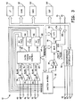
- FIG. 3 is a functional block diagram of IMD 10.
- IMD 10 may take the form of a multi-chamber pacemaker-cardioverter-defibr- illator having a microprocessor-based architecture.
- this diagram should be taken as illustrative of the type of device in which various embodiments of the present invention may be embodied, and not as limiting, as it is believed that the invention may be practiced in a wide variety of device implementations, including devices that provide cardiac resynchronization pacing therapies but do not provide cardioverter and/or defibrillator functionality.
- IMD 10 includes a microprocessor 60.
- Microprocessor 60 may execute program instructions stored in a memory, e.g., a computer-readable medium, such as a ROM (not shown), EEPROM (not shown), and/or RAM 62. Program instruction stored in a computer-readable medium and executed by microprocessor 60 control microprocessor 60 to perform the functions ascribed to microprocessor 60 herein.
- Microprocessor 60 may be coupled to, e.g., to communicate with and/or control, various other components of IMD 10 via an address/data bus 64.
- IMD 10 senses electrical activity within heart 16. Electrodes 30 and 32 are coupled to amplifier 66, which may take the form of an automatic gain controlled amplifier providing an adjustable sensing threshold as a function of the measured R-wave amplitude. A signal is generated on RV out line 68 whenever the signal sensed between electrodes 30 and 32 exceeds the present sensing threshold. Thus electrodes 30 and 32 and amplifier 66 may be used to detect intrinsic right ventricular depolarizations. Electrodes 34 and 36 are coupled to amplifier 70, which also may take the form of an automatic gain controlled amplifier providing an adjustable sensing threshold as a function of measured R-wave amplitude. A signal is generated on LV out line 72 whenever the signal sensed between electrodes 34 and 36 exceeds the present sensing threshold. Thus, electrodes 34 and 36 and amplifier 70 may be used to detect intrinsic left ventricular depolarizations.
- Electrodes 38 and 40 are coupled to amplifier 74, which may take the form of an automatic gain controlled amplifier providing an adjustable sensing threshold as a function of the measured P-wave amplitude. A signal is generated on RA out line 76 whenever the signal between electrodes 38 and 40 exceeds the present sensing threshold. Thus, electrodes 38 and 40 and amplifier 74 may be used to detect intrinsic atrial depolarizations.
- Pacer timing/control circuitry 78 preferably includes programmable digital counters which control the basic time intervals associated with modes of pacing. Circuitry 78 also preferably controls escape intervals associated with pacing. For example, IMD 10 may pace right atrium 24 via timing/control circuitry 78 triggering generation of pacing pulses by pacer output circuit 84, which is coupled to electrodes 38 and 40. Pacer timing/control circuitry 78 may trigger generation of pacing pulses for right atrium 24 upon expiration of an atrial escape interval.
- IMD 10 delivers pacing pulses to right ventricle 18 to synchronize contractions of right ventricle 18 with contractions of left ventricle 22 resulting from intrinsic depolarizations of left ventricle 22.
- Pacer timing/control circuitry 78 triggers generation of pacing pulses for right ventricle 18 by pacer output circuit 80, which is coupled to electrodes 30 and 32.
- circuitry 78 triggers generation of pacing pulses delivered to right ventricle 18 upon expiration of an interval that may be timed from a right atrial pacing pulse or detection of an intrinsic right atrial depolarization.
- IMD 10 may also provide biventricular modes of cardiac resynchronization therapy, or non-resynchronization pacing modalities that require delivery of pacing pulses to left ventricle 22, and may switch from a right ventricular cardiac resynchronization mode as described herein to one of these additional modes.
- Pacer timing/control circuitry 78 triggers generation of pacing pulses for left ventricle 22 by pacer output circuit 82, which is coupled to electrodes 34 and 36.
- Pacer timing/control circuitry 78 may trigger generation of pacing pulses for left ventricle 22 upon expiration of an A-V or V-V escape interval, depending on the pacing mode.
- Output circuits 80, 82 and 84 may be pulse generation circuits, which include capacitors and switches for the storage and delivery of energy as a pulse.
- Pacer timing/control circuitry 78 resets escape interval counters upon detection of R-waves or P-waves, or generation of pacing pulses, and thereby controls the basic timing of cardiac pacing functions. Intervals defined by pacing circuitry 78 may also include refractory periods during which sensed R-waves and P-waves are ineffective to restart timing of escape intervals, and the pulse widths of the pacing pulses. The durations of these intervals are determined by microprocessor 60 in response to data stored in RAM 62, and are communicated to circuitry 78 via address/data bus 64. Pacer timing/control circuitry 78 also determines the amplitude of the cardiac pacing pulses under control of microprocessor 60.
- Microprocessor 60 may operate as an interrupt driven device, and is responsive to interrupts from pacer timing/control circuitry 78 corresponding to the occurrence of sensed P-waves and R-waves and corresponding to the generation of cardiac pacing pulses. Those interrupts are provided via data/address bus 64. Any necessary mathematical calculations to be performed by microprocessor 60 and any updating of the values or intervals controlled by pacer timing/control circuitry 78 take place following such interrupts.
- Microprocessor 60 determines the timing of delivery of pacing pulses to right ventricle 18, i.e., the intervals provided to pacer timing/control circuit 78 to trigger generation of pacing pulses by output circuit 80, based on one or more measured cardiac event intervals corresponding to the sequence of electrical and/or mechanical events, e.g., an interval relating to the first heart sound, and/or measured EGM characteristics, e.g., QRS complex width or Q-T interval, of one or more electrogram signals that represent electrical activity within heart 16.
- IMD 10 receives signals that represent electrical activity within heart 16, and may digitally process the signals to measure characteristics of the signals.
- Switch matrix 92 is used to select which of the available electrodes 30-40 and 48 are coupled to wide band (0.5-200 Hz) amplifier 94 for use in digital signal analysis. As will be described in greater detail below, any of a number of potential combinations of these electrodes may be used, so long as the signal provided by the combination allows for identification and measurement of the desired characteristic. Selection of electrodes is controlled by microprocessor 60 via data/address bus 64, and the selections may be varied as desired.
- the analog signals derived from the selected electrodes and amplified by amplifier 94 are provided to multiplexer 96, and thereafter converted to a multi-bit digital signal by A/D converter 98.
- a digital signal processor (DSP) 100 may process the multi-bit digital signals to measure QRS complex widths and/or Q-T intervals, as will be described in greater detail below.
- the digital signal may be stored in RAM 62 under control of direct memory access circuit 102 for later analysis by DSP 100.
- Analog signals received from right ventricular pressure sensor 26 and heart sound sensor 28 are amplified by amplifiers 104 and 106, respectively, and provided to multiplexer 96.
- the analog sensor signals are thereafter converted to digital signals by A/D converter 98.
- DSP 100 or microprocessor 60 receives the digital signals via address/data bus 64.
- the digital pressure signals are processed by DSP or microprocessor 60 to derive one or more right ventricular pressure parameters.
- the digital heart sound signal is processed by DSP 100 or microprocessor 60 for detecting heart sounds and deriving interval measurements relating to, in particular, the first heart sound.
- analog circuitry may be used to detect the first heart sound using the analog heart sound sensor signal.
- IMD 10 is described herein as having separate processors, microprocessor 60 may perform both the functions ascribed to it herein and digital signal analysis functions ascribed to DSP 100 herein.
- processors which may be microprocessors, DSPs, FPGAs, or other digital logic circuits.
- IMD 10 may not include or utilize DSP 100 to measure QRS complex widths and Q-T intervals.
- IMD 10 may include analog slope or threshold detecting amplifier circuits to identify the beginning and end points of QRS complexes or Q-waves and T-waves.
- pacer timing/control circuit 78 may receive the output of these amplifier circuits, and provide an indication of the occurrence of these events to microprocessor 60 so that microprocessor may measure QRS complex widths and/or Q-T intervals.
- peak detection, slope or threshold detecting amplifier circuits may be used for detecting and deriving right ventricular pressure parameters and the occurrence of the first heart sound.
- IMD 10 may detect ventricular and/or atrial tachycardias or fibrillations of heart 16 using tachycardia and fibrillation detection techniques and algorithms known in the art. For example, the presence of a ventricular or atrial tachycardia or fibrillation may be confirmed by detecting a sustained series of short R-R or P-P intervals of an average rate indicative of tachycardia, or an unbroken series of short R-R or P-P intervals. IMD 10 is also capable of delivering one or more anti-tachycardia pacing (ATP) therapies to heart 16, and cardioversion and/or defibrillation pulses to heart 16 via one or more of electrodes 48, 52, 54 and 56.
- ATP anti-tachycardia pacing
- Electrodes 48, 52, 54 and 56 are coupled to a cardioversion/defibrillation circuit 90, which delivers cardioversion and defibrillation pulses under the control of microprocessor 60.
- Circuit 90 may include energy storage circuits such as capacitors, switches for coupling the storage circuits to electrodes 48, 52, 54 and 56, and logic for controlling the coupling of the storage circuits to the electrodes to create pulses with desired polarities and shapes.
- Microprocessor 60 may employ an escape interval counter to control timing of such cardioversion and defibrillation pulses, as well as associated refractory periods.
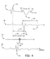
- FIG. 4 is a timing diagram illustrating example electrogram (EGM) signals and heart sound signals that represent electrical and mechanical activity within heart 16.
- Signal 110 is a right atrial EGM.
- IMD 10 may digitally process atrial EGM 110 to measure a width 116 of QRS complex 118.
- Signal 110 may be detected using electrodes 38 and 40 of RA lead 14C in a bipolar configuration, or one of electrodes 38 and 40 and housing electrode 48 in a unipolar configuration.
- IMD 10 digitally processes signals that include far-field QRS complexes 118, such as right atrial EGM 110, to measure widths 116. Processing these far-field signals results in QRS complex measurements that are more "global" in that they reflect depolarization of both ventricles 18, 22, and thus the widths 116 of far-field QRS complexes 118 more accurately reflect ventricular synchrony.
- IMD 10 may detect signals that include far-field QRS complexes using two or more housing electrodes 48.
- DSP 100 In order to measure QRS complex width 116, DSP 100 first identifies far-field QRS complex 118 within signal 110. For example, DSP 100 may receive indications of the occurrence of an R-wave 120 or 122 from pacer timing/control circuit 78, and identify QRS complex 118 based on these indications. As another example, DSP 100 may identify QRS complex 118 by detecting a number of threshold-crossings of the digital signal provided by A/D converter 98, or zero-crossings of the first derivative of the digital signal occurring within a time window. As yet another example, DSP 100 may detect QRS complexes within signals 110, 112 using techniques described in commonly assigned U.S. Pat. No. 6,029,087 (Wohlgemuth ).
- DSP 100 may measure width 116 as a period of time from a beginning point 124 to an ending point 126. DSP 100 may identify beginning point 124 and ending point 126 as threshold-crossings of the digital signal or zero-crossings of the first derivative of the digital signal.
- Signal 112 is a right EGM and is detected via RV lead 14A. Signal 112 may be detected using bipolar electrode pair 30 and 32 or one electrode 30 or 32 and housing electrode 48 in a unipolar configuration. IMD 10 may digitally process signal 112 to measure a Q-T interval 128.
- DSP 100 may receive an indication of delivery of a right ventricular pacing pulse (not shown) from pacer timing/control circuitry 78, and measure Q-T interval 128 as the period of time from the pacing pulse to detection of T-wave 132 within the digital signal provided by A/D converter 98.
- T-wave 132 may, for example, be detected using techniques described in the above-referenced Wohlgemuth '087 Patent.
- DSP 100 may measure multiple QRS complex widths and/or Q-T intervals over multiple cardiac cycles. As will be described in greater detail below, DSP 100 measures these values in response to delivery of pacing pulses to right ventricle 18.
- the values for QRS complex widths 116 and/or Q-T intervals 128 measured by DSP 100 may be stored in RAM 62 for later analysis by microprocessor 60.
- Microprocessor 60 analyzes the measured values to identify the smallest QRS complex width 116 or the largest Q-T interval 128 in response to a range or test right atrial-ventricular (AV) pacing intervals.
- AV right atrial-ventricular
- microprocessor 60 may measure intervals 134 between intrinsic and/or paced atrial depolarizations, e.g., P-waves 136, and intrinsic right ventricular depolarizations, e.g., R-waves 120.
- Microprocessor 60 controls pacer timing/control circuitry 78 to deliver test right ventricular pacing pulses (not shown) at a variety of pacing intervals timed from P-wave 136.
- Microprocessor 60 may control circuit 78 to test pacing intervals within a range defined based on interval 134, for example test AV pacing intervals less than interval 134.
- DSP 100 measures one or both of a QRS complex width 116 and Q-T interval 128 for each pacing interval tested.
- Microprocessor 60 selects the tested pacing interval that microprocessor 60 determines provides the best synchronization between contractions of right and left ventricles 18 and 22, e.g., the pacing interval that resulted in the shortest QRS complex width 116, the longest Q-T interval 128, or the average of the pacing intervals that resulted in the shortest QRS complex width 116 and the longest Q-T interval 128, respectively.
- Microprocessor 60 controls delivery of pacing pulses to right ventricle 18 based on the selected pacing interval, as will be described in greater detail below.
- Signal 114 illustrates a first heart sound (FHS) signal obtained from heart sound sensor 28.
- the R-wave 120 occurs at an interval 144 after the FHS 130 in patients having RBBB.
- Signal 140 illustrates a right ventricular EGM signal obtained from a healthy patient having intact atrial-ventricular conduction.
- R-wave 142 occurs prior to FHS 130, by an interval 148, corresponding to normal ventricular synchrony.
- the interval 144 between an intrinsic R-wave 120 sensed in a patient having RBBB and the FHS 130 is measured for use in determining a pacing interval for pacing the right ventricle 18 to improve synchrony between the right ventricle 18 and the left ventricle 22.
- the interval 146 measured between a P-wave 136 in the right atrium and the FHS 130 in a patient known to have RBBB may be used for selecting a pacing interval for pacing the right ventricle.
- a pacing interval following P-wave 136 may be applied to deliver a pacing pulse prior to FHS 130 to thereby restore the normal temporal relationship between the right ventricular depolarization and FHS 130 as represented, for example, by signal 140.
- FHS 130 may be sensed using a threshold crossing, slope detection, frequency threshold, or other signal processing methods for sensing FHS subsequent to the atrial P-wave 136 or an atrial pacing pulse.
- a range of test AV pacing intervals may be applied to select the AV pacing interval that results in the right ventricular depolarization occurring prior to the FHS by a desired interval corresponding to a normal temporal relationship as represented by signal 140.
- the interval 146 between P-wave 136 and FHS 130 may be set as a maximum right AV pacing interval used in selecting the right AV pacing interval based on other assessments of ventricular synchrony involving measured EGM characteristics and/or right ventricular pressure parameters.
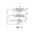
- FIG. 5 is a flow diagram illustrating an example method 150 that IMD 10 may employ to deliver cardiac resynchronization therapy according to one embodiment of the invention.
- Flow chart 150 is intended to illustrate the functional operation of IMD 10, and should not be construed as reflective of a specific form of software or hardware necessary to practice the invention. It is believed that the particular form of software will be determined primarily by the particular system architecture employed in the IMD and by the particular detection and therapy delivery methodologies employed by the IMD. Providing software to accomplish the present invention in the context of any modem IMD, given the disclosure herein, is within the abilities of one of skill in the art.
- a "computer-readable medium” includes but is not limited to any volatile or non-volatile media, such as a RAM, ROM, CD-ROM, NVRAM, EEPROM, flash memory, and the like.
- the instructions may be implemented as one or more software modules, which may be executed by themselves or in combination with other software.
- IMD 10 determines a timing of right ventricular pacing at block 152 that synchronizes the paced contractions of right ventricle 18 with contractions of left ventricle 22 resulting from intrinsic depolarizations of left ventricle 22.
- Processor 60 determines the timing of right ventricular pacing based on measured intervals using electrogram and other sensor signals, including a heart sound sensor.
- Processor 60 controls pacing of right ventricle 18 based on the determined timing at block 154.
- Processor 60 periodically retests the timing of right ventricular pacing, e.g., hourly, daily, or monthly, to account for longer-term changes in the condition of patient 12, as indicated by block 156.
- Method 150 and variations thereof as will be described below can be applied independently of the pacing/sensing sites for the right and left ventricles.
- FIGS. 6-9 further illustrate A method according to FIG. 5 according to various embodiments of the invention.
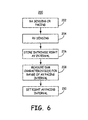
- FIG. 6 illustrates a method 200 that may be employed by IMD 10 to determine the timing based on a measured EGM characteristic.
- right atrial sensing and right ventricular sensing are performed to detect the intrinsic right atrial depolarization (P-wave) and the intrinsic right ventricular depolarization (R-wave).
- the intrinsic right AV interval is measured based on the sensed depolarization signals, for example interval 134 shown in FIG. 4 , at block 206.
- the measured intrinsic right AV interval is stored at block 206 and used in setting a range of test AV pacing intervals applied for pacing the right ventricle.
- test AV pacing intervals are set to multiple settings between a minimum AV interval, for example 30 ms, and a maximum AV interval equal to the measured intrinsic right AV interval.
- EGM characteristics are measured during right ventricular pacing at each applied AV interval.
- the EGM characteristics measured may include the QRS duration (116 in FIG. 4 ) and/or the QT interval (128 in FIG. 4 ).
- the right AV pacing interval for pacing the right ventricle 18 is set based on the measured EGM characteristics.
- the AV pacing interval is set to the interval corresponding to the shortest QRS duration.
- the AV pacing interval is set to the interval corresponding to the longest QT interval.
- the AV pacing interval is set to an interval determined as a function of both of the interval corresponding to the shortest QRS duration and the interval corresponding to the longest QT interval. For example, the AV pacing interval may be set as an average of these intervals.
- method 200 may be performed during both atrial sensing and atrial pacing.
- the interval measured at block 206 may be a right AV interval corresponding to a right atrial pace and the intrinsic right ventricular depolarization following the right atrial pace.
- a range of test AV pacing intervals may then be applied following the right atrial pace.
- the range of test AV pacing intervals can be defined based on the measured right atrial pace to intrinsic right ventricular depolarization interval. For example the measured right atrial pace to intrinsic right ventricular depolarization interval may be used as a maximum AV pacing interval.
- the EGM characteristics measured at block 208 are measured during right atrial and right ventricular pacing over the range of test AV pacing intervals.
- the right AV pacing interval set at block 210 based on EGM characteristics measured during right atrial pacing may be stored separately from the right AV pacing interval determined during right atrial sensing. Accordingly, a different right AV pacing interval for synchronizing the right ventricle 18 with the left ventricle 22 may be applied during right atrial pacing than during right atrial sensing.
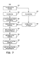
- FIG. 7 is flow chart of a method 220 that may be employed by IMD 10 to determine the right ventricular pacing timing based on a measured interval between cardiac cycle events.
- the right ventricular pacing timing is regulated relative to the FHS.
- right atrial sensing and right ventricular sensing are performed as described above for measuring an intrinsic right AV interval at block 226.
- Method 220 may additionally or alternatively be performed during right atrial pacing, as indicated at block 222, for measuring an interval between a right atrial pace and subsequent intrinsic right ventricular depolarization.
- method 220 is used to set an AV pacing interval to be applied to the right ventricle 18 during right atrial pacing for synchronizing the right and left ventricles 18 and 22.
- the heart sound sensor 28 is used to sense the occurrence of the first heart sound.
- An interval between the atrial sense/pace and the FHS (A-FHS interval) is measured at block 230.
- this interval may be used for setting the right AV pacing interval to synchronize the RV depolarization relative to the FHS.
- the A-FHS interval stored at block 230 less a predetermined offset may be set as the right AV pacing interval such that the right ventricle 18 is paced at the predetermined offset prior to the FHS.
- the AV pacing interval is set as the A-FHS interval less an offset of about 10 to 200 ms.
- the difference between the intrinsic AV interval and the A- FHS interval is computed as the RV-FHS interval. This difference may be used to determine a right AV pacing interval that results in an improved temporal relation between the RV depolarization and the FHS in a patient having RBBB.
- a range of test AV pacing intervals is applied to pace the right ventricle 18.
- the range of test AV pacing intervals may be defined based on the measured intrinsic AV interval as described previously. Alternatively, the range of test AV pacing intervals may be defined based on the measured A-FHS interval, e.g. the maximum test AV pacing interval may equal to the A-FHS interval.
- the RV-FHS interval is determined for each respective AV pacing interval.
- the AV pacing interval that results in an RV-FHS interval that is considered to be physiologically acceptable, i.e., associated with improved RV-LV synchrony, is set as the right AV pacing interval.
- the AV pacing interval that results in an RV-FHS interval of about 40 ms, i.e. the RV depolarization occurs about 40 ms prior to the FHS, is selected at block 238 as the right AV pacing interval.
- the RV-FHS interval may be measured on a beat-by-beat or other periodic basis for dynamically resetting the AV pacing interval to maintain ventricular synchrony.
- the RV-FHS interval measurement performed on each cardiac cycle may be used to adjust the AV pacing interval on subsequent cardiac cycles.
- a rolling average of the RV-FHS interval is determined for a predetermined number of cardiac cycles. If the rolling average begins to increase greater than the desired RV-FHS interval, the right AV pacing interval may be lengthened to pace the RV somewhat later in the cardiac cycle. If the rolling average begins to decrease, the right AV pacing interval may be shortened to pace the RV somewhat earlier in the cardiac cycle.
- the method 220 may return to block 234 to reassess a range of test AV pacing intervals and reset the right AV pacing interval at block 238 based on RV-FHS interval measurements.
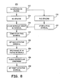
- FIG. 8 is a flow chart of an alternative method 250 for setting a right AV pacing interval for improving RV-LV synchrony.
- blocks 222 through 232 correspond to identically numbered blocks described in conjunction with method 220 of FIG. 7 .
- a maximum AV pacing interval may be defined based on the measured A-FHS interval (block 230). This maximum AV pacing interval prevents the pacing interval to be set based on other parameter assessment to an interval that results in RV pacing after the FHS.
- a range of test AV pacing intervals are applied, which may be set between a minimum and the maximum AV pacing interval set at block 252.
- ventricular synchrony is assessed by measuring one or more ventricular synchrony metrics for each respective test AV pacing interval. EGM characteristics, such as QRS width and QT interval may be measured to assess ventricular synchrony at block 256.
- a right ventricular pressure parameter as derived from an RV pressure sensor signal, may be determined as a ventricular synchrony metric.
- RV pressure parameters may include dP/dtmax, dP/dtmin, end diastolic pressure, and an estimated pulmonary artery diastolic pressure.
- the right AV pacing interval is set as a function of the AV pacing intervals corresponding to the optimal ventricular synchrony as indicated by the measured ventricular synchrony metrics. For example, the test AV pacing intervals corresponding to each of the minimum QRS duration, maximum QT interval, maximum RV dp/dt(max), minimum RV end diastolic pressure, and/or minimum estimated diastolic pulmonary artery pressure may be determined. The RV-FHS interval may additionally be measured for each AV pacing interval.
- the right AV pacing interval may then be set at block 258 to an interval corresponding to any of these optimal ventricular synchrony metrics or as a function of any combination of these intervals.
- the right AV pacing interval is set to be equal to or less than the maximum interval determined at block 252 to maintain a normal temporal relationship between the RV depolarization and the FHS.
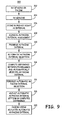
- FIG. 9 is a flow chart of another method 300 for controlling RV pacing for improving synchrony of the RV with intrinsic LV depolarizations.
- right atrial sensing/pacing and right ventricular sensing are performed for measuring an intrinsic right AV interval at block 306.
- a clinical assessment of RV-LV synchrony is performed while applying a range of AV pacing intervals.
- the range of AV pacing intervals may be selected based on the measured intrinsic right AV interval as described previously.
- the clinical assessment may include ECG analysis, echocardiogram analysis, heart sound analysis, fluoroscopy, or other clinical evaluation tools.
- a right AV pacing interval determined to improve RV-LV synchrony based on the clinical assessment is programmed by a clinician.
- an automatic AV pacing interval selection is performed by IMD 10.
- the automatic AV pacing interval selection method may correspond to any of the methods shown in FIGs. 6-8 or any combination of these methods.
- the automatic AV pacing interval selection may include determining the timing of the right ventricular depolarization relative to the FHS as well as determining other ventricular synchrony metrics, such as EGM characteristics and RV pressure parameters.
- the automatic selection method is performed to determine an AV pacing interval setting that optimally improves ventricular synchrony according to IMD-measured parameters.
- the automatically selected AV pacing interval is determined immediately after programming the AV pacing interval such that a difference between the programmed and automatically selected AV pacing interval may be determined.
- the difference between an AV pacing interval determined by the automatic selection method for optimally improving ventricular synchrony and the programmed AV pacing interval is computed at block 314.
- the difference is not used to adjust the currently programmed AV pacing interval. Rather, this difference is stored for use in adjusting automatically selected AV pacing intervals upon subsequent AV pacing interval assessments.
- the AV pacing interval selected by the automatic selection method is adjusted by the difference computed at block 318 between the automatically selected AV pacing interval determined previously and a clinically determined AV pacing interval.
- the adjusted automatic AV pacing interval is used to pace the right ventricle at block 320.
Landscapes
- Health & Medical Sciences (AREA)
- Life Sciences & Earth Sciences (AREA)
- Heart & Thoracic Surgery (AREA)
- Cardiology (AREA)
- Public Health (AREA)
- Engineering & Computer Science (AREA)
- Biomedical Technology (AREA)
- Veterinary Medicine (AREA)
- Animal Behavior & Ethology (AREA)
- General Health & Medical Sciences (AREA)
- Medical Informatics (AREA)
- Surgery (AREA)
- Molecular Biology (AREA)
- Hematology (AREA)
- Biophysics (AREA)
- Physiology (AREA)
- Nuclear Medicine, Radiotherapy & Molecular Imaging (AREA)
- Radiology & Medical Imaging (AREA)
- Electrotherapy Devices (AREA)
- Medicines Containing Material From Animals Or Micro-Organisms (AREA)
- External Artificial Organs (AREA)
Claims (9)
- Implantierbare medizinische Vorrichtung, um eine Herzresynchronisationstherapie in einem Patienten zu schaffen, der einen Rechtsschenkelblock hat, wobei die Vorrichtung enthält:Elektroden (30, 32, 34, 36, 38, 40), um elektrische Signale in einem Herzen zu detektieren und um Schrittmacherimpulse an das Herz zu verabreichen;eine Erfassungsschaltungsanordnung (66, 70, 74), um die elektrischen Signale von den Elektroden zu empfangen;eine Impulserzeugungsschaltungsanordnung (78), um die Schrittmacherimpulse zu erzeugen, die durch die Elektroden verabreicht werden;einen Herzschallsensor (28); undeinen Prozessor (60), der mit der Erfassungsschaltungsanordnung, mit der Impulserzeugungsschaltungsanordnung und mit dem Herzschallsensor gekoppelt ist; dadurch gekennzeichnet, dass der Prozessor konfiguriert ist, um ein erstes Intervall zwischen einem rechten atrialen Depolarisationssignal und einem ersten Herzschallsignal zu messen, ein rechtes atrio-ventrikuläres Schrittmacherintervall (AV-Schrittmacherintervall) in Reaktion auf das gemessene erste Intervall auszuwählen; und die Verabreichung der Schrittmacherimpulse an einen rechten Ventrikel eines Herzens in dem ausgewählten rechten AV-Schrittmacherintervall zu steuern.
- Vorrichtung nach Anspruch 1, wobei der Prozessor konfiguriert ist, um das rechte AV-Schrittmacherintervall als das gemessene erste Intervall abzüglich eines Versatzes auszuwählen.
- Vorrichtung nach Anspruch 2, wobei der Versatz im Bereich von 10 ms bis 200 ms liegt.
- Vorrichtung nach Anspruch 1, wobei der Prozessor ferner konfiguriert ist, um:ein zweites Intervall zwischen dem rechten atrialen Depolarisationssignal und einem erfassten rechten ventrikulären Depolarisationssignal zu messen;die Verabreichung von Schrittmacherimpulsen an dem rechten Ventrikel in mehreren Test-AV-Schrittmacherintervallen, die anhand des zweiten Intervalls bestimmt werden, zu steuern; undeine Bewertung der ventrikulären Synchronizität durch Bestimmen einer Metrik der ventrikulären Synchronizität für jedes der mehreren Test-AV-Schrittmacherintervalle auszuführen;wobei die Auswahl des rechten AV-Schrittmacherintervalls durch den Prozessor das Vergleichen der Metrik der ventrikulären Synchronizität für jedes der mehreren Test-AV-Schrittmacherintervalle enthält.
- Vorrichtung nach Anspruch 4, wobei die Bewertung der ventrikulären Synchronizität, die durch den Prozessor ausgeführt wird, das Berechnen eines dritten Intervalls zwischen der rechten ventrikulären Depolarisation und dem ersten Herzschall für jedes der mehreren Test-AV-Schrittmacherintervalle enthält.
- Vorrichtung nach Anspruch 4, wobei die Bewertung der ventrikulären Synchronizität, die durch den Prozessor ausgeführt wird, das Messen einer Herzelektrogramm-Charakteristik für jedes der mehreren Test-AV-Schrittmacherintervalle enthält.
- Vorrichtung nach Anspruch 4, wobei die Bewertung der ventrikulären Synchronizität, die durch den Prozessor ausgeführt wird, das Messen eines Parameters des rechten ventrikulären Drucks für jedes der mehreren Test-AV-Schrittmacherintervalle enthält.
- Vorrichtung nach Anspruch 4, wobei der Prozessor ferner konfiguriert ist, um:eine Differenz zwischen dem ausgewählten rechten AV-Schrittmacherintervall und einem programmierten Intervall zu bestimmen;das ausgewählte AV-Schrittmacherintervall durch die Differenz einzustellen;die Bewertung der ventrikulären Synchronizität zu wiederholen, um das nächste ausgewählte rechte AV-Schrittmacherintervall zu bestimmen; unddas nächste ausgewählte AV-Schrittmacherintervall durch die Differenz einzustellen.
- Computerlesbares Medium, in dem eine Menge von Befehlen gespeichert ist, die, wenn sie in einer implantierbaren medizinischen Vorrichtung nach einem vorhergehenden Anspruch zum Verabreichen einer Herzresynchronisationstherapie implementiert sind, die Vorrichtung dazu veranlassen:ein erstes Intervall zwischen einem rechten atrialen Depolarisationssignal und einem ersten Herzschallsignal zu messen;ein rechtes atrio-ventrikuläres Schrittmacherintervall (AV-Schrittmacherintervall) in Reaktion auf das gemessene erste Intervall auszuwählen; undSchrittmacherimpulse an einen rechten Ventrikel eines Herzens in dem rechten AV-Schrittmacherintervall zu verabreichen.
Applications Claiming Priority (2)
| Application Number | Priority Date | Filing Date | Title |
|---|---|---|---|
| US11/831,403 US8041424B2 (en) | 2007-07-31 | 2007-07-31 | Cardiac resynchronization therapy for patients with right bundle branch block |
| PCT/US2008/070437 WO2009017986A1 (en) | 2007-07-31 | 2008-07-18 | Cardiac resynchronization therapy for patients with right bundle branch block |
Publications (2)
| Publication Number | Publication Date |
|---|---|
| EP2188010A1 EP2188010A1 (de) | 2010-05-26 |
| EP2188010B1 true EP2188010B1 (de) | 2011-05-04 |
Family
ID=39811565
Family Applications (1)
| Application Number | Title | Priority Date | Filing Date |
|---|---|---|---|
| EP08796280A Active EP2188010B1 (de) | 2007-07-31 | 2008-07-18 | Herzresynchronisationstherapie für patienten mit rechtsbündelblock |
Country Status (5)
| Country | Link |
|---|---|
| US (1) | US8041424B2 (de) |
| EP (1) | EP2188010B1 (de) |
| AT (1) | ATE507873T1 (de) |
| DE (1) | DE602008006742D1 (de) |
| WO (1) | WO2009017986A1 (de) |
Families Citing this family (95)
| Publication number | Priority date | Publication date | Assignee | Title |
|---|---|---|---|---|
| US20120109244A1 (en) * | 2010-11-03 | 2012-05-03 | Pacesetter, Inc. | Parameters in monitoring cardiac resynchronization therapy response |
| US8923963B2 (en) * | 2012-10-31 | 2014-12-30 | Medtronic, Inc. | Leadless pacemaker system |
| WO2014099595A2 (en) | 2012-12-19 | 2014-06-26 | Cardiac Pacemakers, Inc. | Method and apparatus for right ventricular resynchronization |
| JP6437997B2 (ja) | 2013-03-12 | 2018-12-12 | カーディアック ペースメイカーズ, インコーポレイテッド | 複数のセンサの融合を備えた医療デバイス |
| US9180301B2 (en) | 2013-03-15 | 2015-11-10 | Cardiac Pacemakers, Inc. | Estimating electromechanical delay to optimize pacing parameters in RBBB patients |
| US9511233B2 (en) | 2013-11-21 | 2016-12-06 | Medtronic, Inc. | Systems and methods for leadless cardiac resynchronization therapy |
| US20150196769A1 (en) | 2014-01-10 | 2015-07-16 | Cardiac Pacemakers, Inc. | Methods and systems for improved communication between medical devices |
| CN106068141B (zh) | 2014-01-10 | 2019-05-14 | 心脏起搏器股份公司 | 用于检测心脏心律失常的系统和方法 |
| US9669224B2 (en) | 2014-05-06 | 2017-06-06 | Medtronic, Inc. | Triggered pacing system |
| US9492671B2 (en) | 2014-05-06 | 2016-11-15 | Medtronic, Inc. | Acoustically triggered therapy delivery |
| US9526909B2 (en) | 2014-08-28 | 2016-12-27 | Cardiac Pacemakers, Inc. | Medical device with triggered blanking period |
| WO2016126613A1 (en) | 2015-02-06 | 2016-08-11 | Cardiac Pacemakers, Inc. | Systems and methods for treating cardiac arrhythmias |
| EP3253449B1 (de) | 2015-02-06 | 2018-12-12 | Cardiac Pacemakers, Inc. | Systeme zur sicheren verabreichung von elektrischer stimulationstherapie |
| WO2016130477A2 (en) | 2015-02-09 | 2016-08-18 | Cardiac Pacemakers, Inc. | Implantable medical device with radiopaque id tag |
| WO2016141046A1 (en) | 2015-03-04 | 2016-09-09 | Cardiac Pacemakers, Inc. | Systems and methods for treating cardiac arrhythmias |
| CN107427222B (zh) | 2015-03-18 | 2021-02-09 | 心脏起搏器股份公司 | 使用链路质量评估的医疗设备系统中的通信 |
| US10050700B2 (en) | 2015-03-18 | 2018-08-14 | Cardiac Pacemakers, Inc. | Communications in a medical device system with temporal optimization |
| US10327648B2 (en) | 2015-04-01 | 2019-06-25 | Siemens Healthcare Gmbh | Blood vessel mechanical signal analysis |
| US9853743B2 (en) | 2015-08-20 | 2017-12-26 | Cardiac Pacemakers, Inc. | Systems and methods for communication between medical devices |
| WO2017031347A1 (en) | 2015-08-20 | 2017-02-23 | Cardiac Pacemakers, Inc. | Systems and methods for communication between medical devices |
| US9956414B2 (en) | 2015-08-27 | 2018-05-01 | Cardiac Pacemakers, Inc. | Temporal configuration of a motion sensor in an implantable medical device |
| US9968787B2 (en) | 2015-08-27 | 2018-05-15 | Cardiac Pacemakers, Inc. | Spatial configuration of a motion sensor in an implantable medical device |
| US10226631B2 (en) | 2015-08-28 | 2019-03-12 | Cardiac Pacemakers, Inc. | Systems and methods for infarct detection |
| EP3341076B1 (de) | 2015-08-28 | 2022-05-11 | Cardiac Pacemakers, Inc. | Systeme und verfahren zur detektion von verhaltensreaktionssignalen und verabreichung einer therapie |
| WO2017040115A1 (en) | 2015-08-28 | 2017-03-09 | Cardiac Pacemakers, Inc. | System for detecting tamponade |
| US10092760B2 (en) | 2015-09-11 | 2018-10-09 | Cardiac Pacemakers, Inc. | Arrhythmia detection and confirmation |
| WO2017062806A1 (en) | 2015-10-08 | 2017-04-13 | Cardiac Pacemakers, Inc. | Devices and methods for adjusting pacing rates in an implantable medical device |
| US10183170B2 (en) | 2015-12-17 | 2019-01-22 | Cardiac Pacemakers, Inc. | Conducted communication in a medical device system |
| US10905886B2 (en) | 2015-12-28 | 2021-02-02 | Cardiac Pacemakers, Inc. | Implantable medical device for deployment across the atrioventricular septum |
| US10583303B2 (en) | 2016-01-19 | 2020-03-10 | Cardiac Pacemakers, Inc. | Devices and methods for wirelessly recharging a rechargeable battery of an implantable medical device |
| EP3411113B1 (de) | 2016-02-04 | 2019-11-27 | Cardiac Pacemakers, Inc. | Einführungssystem mit kraftsensor für drahtlose kardiale vorrichtung |
| US9731138B1 (en) | 2016-02-17 | 2017-08-15 | Medtronic, Inc. | System and method for cardiac pacing |
| US10780279B2 (en) * | 2016-02-26 | 2020-09-22 | Medtronic, Inc. | Methods and systems of optimizing right ventricular only pacing for patients with respect to an atrial event and left ventricular event |
| WO2017173275A1 (en) | 2016-03-31 | 2017-10-05 | Cardiac Pacemakers, Inc. | Implantable medical device with rechargeable battery |
| US9802055B2 (en) | 2016-04-04 | 2017-10-31 | Medtronic, Inc. | Ultrasound powered pulse delivery device |
| US10668294B2 (en) | 2016-05-10 | 2020-06-02 | Cardiac Pacemakers, Inc. | Leadless cardiac pacemaker configured for over the wire delivery |
| US10328272B2 (en) | 2016-05-10 | 2019-06-25 | Cardiac Pacemakers, Inc. | Retrievability for implantable medical devices |
| EP3474945B1 (de) | 2016-06-27 | 2022-12-28 | Cardiac Pacemakers, Inc. | Herztherapiesystem unter verwendung von subkutan gemessenen p-wellen zur resynchronisation der stimulationsverwaltung |
| US11207527B2 (en) | 2016-07-06 | 2021-12-28 | Cardiac Pacemakers, Inc. | Method and system for determining an atrial contraction timing fiducial in a leadless cardiac pacemaker system |
| US10426962B2 (en) | 2016-07-07 | 2019-10-01 | Cardiac Pacemakers, Inc. | Leadless pacemaker using pressure measurements for pacing capture verification |
| CN109475743B (zh) | 2016-07-20 | 2022-09-02 | 心脏起搏器股份公司 | 在无引线心脏起搏器系统中利用心房收缩定时基准的系统 |
| CN109562269B (zh) | 2016-08-19 | 2023-08-11 | 心脏起搏器股份公司 | 经隔膜可植入医疗设备 |
| CN109640809B (zh) | 2016-08-24 | 2021-08-17 | 心脏起搏器股份公司 | 使用p波到起搏定时的集成式多装置心脏再同步治疗 |
| WO2018039322A1 (en) | 2016-08-24 | 2018-03-01 | Cardiac Pacemakers, Inc. | Cardiac resynchronization using fusion promotion for timing management |
| US10758737B2 (en) | 2016-09-21 | 2020-09-01 | Cardiac Pacemakers, Inc. | Using sensor data from an intracardially implanted medical device to influence operation of an extracardially implantable cardioverter |
| US10905889B2 (en) | 2016-09-21 | 2021-02-02 | Cardiac Pacemakers, Inc. | Leadless stimulation device with a housing that houses internal components of the leadless stimulation device and functions as the battery case and a terminal of an internal battery |
| WO2018057626A1 (en) | 2016-09-21 | 2018-03-29 | Cardiac Pacemakers, Inc. | Implantable cardiac monitor |
| CN109890457B (zh) | 2016-10-27 | 2023-07-04 | 心脏起搏器股份公司 | 单独的设备在管理心脏起搏器的起搏脉冲能量时的使用 |
| CN109890458B (zh) | 2016-10-27 | 2023-08-11 | 心脏起搏器股份公司 | 具有压力传感器的可植入医疗设备 |
| US10413733B2 (en) | 2016-10-27 | 2019-09-17 | Cardiac Pacemakers, Inc. | Implantable medical device with gyroscope |
| US10561330B2 (en) | 2016-10-27 | 2020-02-18 | Cardiac Pacemakers, Inc. | Implantable medical device having a sense channel with performance adjustment |
| US10758724B2 (en) | 2016-10-27 | 2020-09-01 | Cardiac Pacemakers, Inc. | Implantable medical device delivery system with integrated sensor |
| WO2018081275A1 (en) | 2016-10-27 | 2018-05-03 | Cardiac Pacemakers, Inc. | Multi-device cardiac resynchronization therapy with timing enhancements |
| CN109952128B (zh) | 2016-10-31 | 2023-06-13 | 心脏起搏器股份公司 | 用于活动水平起搏的系统 |
| US10617874B2 (en) | 2016-10-31 | 2020-04-14 | Cardiac Pacemakers, Inc. | Systems and methods for activity level pacing |
| US10583301B2 (en) | 2016-11-08 | 2020-03-10 | Cardiac Pacemakers, Inc. | Implantable medical device for atrial deployment |
| CN109952129B (zh) | 2016-11-09 | 2024-02-20 | 心脏起搏器股份公司 | 为心脏起搏设备设定心脏起搏脉冲参数的系统、设备和方法 |
| WO2018093605A1 (en) | 2016-11-21 | 2018-05-24 | Cardiac Pacemakers, Inc. | Leadless cardiac pacemaker providing cardiac resynchronization therapy |
| JP6843240B2 (ja) | 2016-11-21 | 2021-03-17 | カーディアック ペースメイカーズ, インコーポレイテッド | 透磁性ハウジング及びハウジングの周りに配置された誘導コイルを備える植込み型医療装置 |
| US10639486B2 (en) | 2016-11-21 | 2020-05-05 | Cardiac Pacemakers, Inc. | Implantable medical device with recharge coil |
| US10881869B2 (en) | 2016-11-21 | 2021-01-05 | Cardiac Pacemakers, Inc. | Wireless re-charge of an implantable medical device |
| WO2018094344A2 (en) | 2016-11-21 | 2018-05-24 | Cardiac Pacemakers, Inc | Leadless cardiac pacemaker with multimode communication |
| US11207532B2 (en) | 2017-01-04 | 2021-12-28 | Cardiac Pacemakers, Inc. | Dynamic sensing updates using postural input in a multiple device cardiac rhythm management system |
| US10029107B1 (en) | 2017-01-26 | 2018-07-24 | Cardiac Pacemakers, Inc. | Leadless device with overmolded components |
| CN110198759B (zh) | 2017-01-26 | 2023-08-11 | 心脏起搏器股份公司 | 具有可拆卸固定件的无引线可植入装置 |
| AU2018213326B2 (en) | 2017-01-26 | 2020-09-10 | Cardiac Pacemakers, Inc. | Intra-body device communication with redundant message transmission |
| US10905872B2 (en) | 2017-04-03 | 2021-02-02 | Cardiac Pacemakers, Inc. | Implantable medical device with a movable electrode biased toward an extended position |
| EP3606605B1 (de) | 2017-04-03 | 2023-12-20 | Cardiac Pacemakers, Inc. | Herzschrittmacher mit einstellung der pulsenergie basierend auf der erfassten herzfrequenz |
| US10918875B2 (en) | 2017-08-18 | 2021-02-16 | Cardiac Pacemakers, Inc. | Implantable medical device with a flux concentrator and a receiving coil disposed about the flux concentrator |
| EP3668592B1 (de) | 2017-08-18 | 2021-11-17 | Cardiac Pacemakers, Inc. | Implantierbare medizinische vorrichtung mit drucksensor |
| JP6938778B2 (ja) | 2017-09-20 | 2021-09-22 | カーディアック ペースメイカーズ, インコーポレイテッド | 複数の作動モードを備えた移植式医療用装置 |
| US11185703B2 (en) | 2017-11-07 | 2021-11-30 | Cardiac Pacemakers, Inc. | Leadless cardiac pacemaker for bundle of his pacing |
| CN111432875B (zh) | 2017-12-01 | 2024-04-30 | 心脏起搏器股份公司 | 从心室植入式无引线心脏起搏器检测心房收缩定时基准并确定心脏间隔的方法和系统 |
| CN111432874A (zh) * | 2017-12-01 | 2020-07-17 | 心脏起搏器股份公司 | 从心室植入的无引线心脏起搏器检测搜索窗口内心房收缩定时基准的方法和系统 |
| EP3717064B1 (de) | 2017-12-01 | 2023-06-07 | Cardiac Pacemakers, Inc. | Verfahren und systeme zur erfassung von atrialen kontraktionstaktmarkern während einer ventrikelfüllung aus einem ventrikulär implantierten leitungslosen herzschrittmacher |
| US11813463B2 (en) | 2017-12-01 | 2023-11-14 | Cardiac Pacemakers, Inc. | Leadless cardiac pacemaker with reversionary behavior |
| EP3735293B1 (de) | 2018-01-04 | 2022-03-09 | Cardiac Pacemakers, Inc. | Zweikammer-stimulation ohne schlag-zu-schlag-kommunikation |
| US11529523B2 (en) | 2018-01-04 | 2022-12-20 | Cardiac Pacemakers, Inc. | Handheld bridge device for providing a communication bridge between an implanted medical device and a smartphone |
| JP2021519117A (ja) | 2018-03-23 | 2021-08-10 | メドトロニック,インコーポレイテッド | 頻拍のためのVfA心臓治療 |
| WO2019183512A1 (en) | 2018-03-23 | 2019-09-26 | Medtronic, Inc. | Vfa cardiac resynchronization therapy |
| CN120267967A (zh) | 2018-03-23 | 2025-07-08 | 美敦力公司 | Av同步vfa心脏治疗 |
| US10596383B2 (en) | 2018-04-03 | 2020-03-24 | Medtronic, Inc. | Feature based sensing for leadless pacing therapy |
| JP2022501085A (ja) | 2018-09-26 | 2022-01-06 | メドトロニック,インコーポレイテッド | 心房からの心室心臓治療における捕捉 |
| US11951313B2 (en) | 2018-11-17 | 2024-04-09 | Medtronic, Inc. | VFA delivery systems and methods |
| US12296177B2 (en) | 2018-12-21 | 2025-05-13 | Medtronic, Inc. | Delivery systems and methods for left ventricular pacing |
| US11679265B2 (en) | 2019-02-14 | 2023-06-20 | Medtronic, Inc. | Lead-in-lead systems and methods for cardiac therapy |
| US11697025B2 (en) | 2019-03-29 | 2023-07-11 | Medtronic, Inc. | Cardiac conduction system capture |
| US11213676B2 (en) | 2019-04-01 | 2022-01-04 | Medtronic, Inc. | Delivery systems for VfA cardiac therapy |
| US11712188B2 (en) | 2019-05-07 | 2023-08-01 | Medtronic, Inc. | Posterior left bundle branch engagement |
| US11305127B2 (en) | 2019-08-26 | 2022-04-19 | Medtronic Inc. | VfA delivery and implant region detection |
| US11813466B2 (en) | 2020-01-27 | 2023-11-14 | Medtronic, Inc. | Atrioventricular nodal stimulation |
| US11911168B2 (en) | 2020-04-03 | 2024-02-27 | Medtronic, Inc. | Cardiac conduction system therapy benefit determination |
| US20220031221A1 (en) * | 2020-07-30 | 2022-02-03 | Medtronic, Inc. | Patient screening and ecg belt for brady therapy tuning |
| US12465770B2 (en) | 2020-07-31 | 2025-11-11 | Medtronic, Inc. | Coronary sinus conduction system pacing and delivery |
| US11813464B2 (en) | 2020-07-31 | 2023-11-14 | Medtronic, Inc. | Cardiac conduction system evaluation |
Family Cites Families (22)
| Publication number | Priority date | Publication date | Assignee | Title |
|---|---|---|---|---|
| US5814077A (en) * | 1992-11-13 | 1998-09-29 | Pacesetter, Inc. | Pacemaker and method of operating same that provides functional atrial cardiac pacing with ventricular support |
| US5330511A (en) * | 1993-01-19 | 1994-07-19 | Vitatron Medical B.V. | Dual chamber pacemaker with automatically optimized AV delay |
| US5368040A (en) * | 1993-08-02 | 1994-11-29 | Medtronic, Inc. | Apparatus and method for determining a plurality of hemodynamic variables from a single, chroniclaly implanted absolute pressure sensor |
| US5554177A (en) * | 1995-03-27 | 1996-09-10 | Medtronic, Inc. | Method and apparatus to optimize pacing based on intensity of acoustic signal |
| US5836987A (en) * | 1995-11-15 | 1998-11-17 | Cardiac Pacemakers, Inc. | Apparatus and method for optimizing cardiac performance by determining the optimal timing interval from an accelerometer signal |
| US5700283A (en) * | 1996-11-25 | 1997-12-23 | Cardiac Pacemakers, Inc. | Method and apparatus for pacing patients with severe congestive heart failure |
| US6029087A (en) * | 1998-09-22 | 2000-02-22 | Vitatron Medical, B.V. | Cardiac pacing system with improved physiological event classification based on DSP |
| US6480733B1 (en) * | 1999-11-10 | 2002-11-12 | Pacesetter, Inc. | Method for monitoring heart failure |
| US6643548B1 (en) * | 2000-04-06 | 2003-11-04 | Pacesetter, Inc. | Implantable cardiac stimulation device for monitoring heart sounds to detect progression and regression of heart disease and method thereof |
| US6792308B2 (en) * | 2000-11-17 | 2004-09-14 | Medtronic, Inc. | Myocardial performance assessment |
| US6665564B2 (en) * | 2001-05-21 | 2003-12-16 | Cardiac Pacemakers, Inc. | Cardiac rhythm management system selecting A-V delay based on interval between atrial depolarization and mitral valve closure |
| US6882882B2 (en) * | 2002-04-22 | 2005-04-19 | Medtronic, Inc. | Atrioventricular delay adjustment |
| US6869404B2 (en) * | 2003-02-26 | 2005-03-22 | Medtronic, Inc. | Apparatus and method for chronically monitoring heart sounds for deriving estimated blood pressure |
| US20040230229A1 (en) * | 2003-04-11 | 2004-11-18 | Lovett Eric G. | Hybrid transthoracic/intrathoracic cardiac stimulation devices and methods |
| US7558626B2 (en) * | 2003-04-23 | 2009-07-07 | Medtronic, Inc. | Cardiac resynchronization via left ventricular pacing |
| US7123960B2 (en) * | 2003-12-22 | 2006-10-17 | Cardiac Pacemakers, Inc. | Method and system for delivering cardiac resynchronization therapy with variable atrio-ventricular delay |
| US7209786B2 (en) * | 2004-06-10 | 2007-04-24 | Cardiac Pacemakers, Inc. | Method and apparatus for optimization of cardiac resynchronization therapy using heart sounds |
| US20060178586A1 (en) * | 2005-02-07 | 2006-08-10 | Dobak John D Iii | Devices and methods for accelerometer-based characterization of cardiac function and identification of LV target pacing zones |
| US7751884B2 (en) * | 2005-04-28 | 2010-07-06 | Cardiac Pacemakers, Inc. | Flexible neural stimulation engine |
| US7537569B2 (en) * | 2005-04-29 | 2009-05-26 | Medtronic, Inc. | Method and apparatus for detection of tachyarrhythmia using cycle lengths |
| US7526338B1 (en) * | 2005-05-23 | 2009-04-28 | Pacesetter, Inc. | Implantable cardiac device for monitoring diastolic heart failure and method of operation and use thereof |
| US7546161B1 (en) * | 2006-01-11 | 2009-06-09 | Pacesetter, Inc. | Methods for loss of capture and fusion avoidance in biventricular pacing therapy |
-
2007
- 2007-07-31 US US11/831,403 patent/US8041424B2/en active Active
-
2008
- 2008-07-18 WO PCT/US2008/070437 patent/WO2009017986A1/en not_active Ceased
- 2008-07-18 EP EP08796280A patent/EP2188010B1/de active Active
- 2008-07-18 AT AT08796280T patent/ATE507873T1/de not_active IP Right Cessation
- 2008-07-18 DE DE602008006742T patent/DE602008006742D1/de active Active
Also Published As
| Publication number | Publication date |
|---|---|
| DE602008006742D1 (de) | 2011-06-16 |
| WO2009017986A1 (en) | 2009-02-05 |
| EP2188010A1 (de) | 2010-05-26 |
| US20090036941A1 (en) | 2009-02-05 |
| ATE507873T1 (de) | 2011-05-15 |
| US8041424B2 (en) | 2011-10-18 |
Similar Documents
| Publication | Publication Date | Title |
|---|---|---|
| EP2188010B1 (de) | Herzresynchronisationstherapie für patienten mit rechtsbündelblock | |
| US8024041B2 (en) | Cardiac resynchronization via left ventricular pacing | |
| US7515959B2 (en) | Delivery of CRT therapy during AT/AF termination | |
| US9604064B2 (en) | Criteria for optimal electrical resynchronization during fusion pacing | |
| JP5128707B2 (ja) | 内因性伝導の追跡による動的心臓再同期療法 | |
| US8929984B2 (en) | Criteria for optimal electrical resynchronization during fusion pacing | |
| US20170326368A1 (en) | Modifying atrioventricular delay based on activation times | |
| US20130165983A1 (en) | Monitoring activation times for use in determining pacing effectivness | |
| US20220257954A1 (en) | Delivery of cardiac pacing therapy for cardiac remodeling | |
| EP3806950B1 (de) | Verabreichung einer herzsstimulationstherapie zur herzremodellierung | |
| EP1663388B1 (de) | Elektrisch effiziente neural erregbare stimulation | |
| AU2004280239A1 (en) | Refractory period tracking and arrhythmia detection | |
| US7603172B2 (en) | System and method of using regression models to estimate vulnerable periods for heart stimulation parameters | |
| US20030100926A1 (en) | Rate responsive pacing system with QT sensor based on intrinsic QT data | |
| US6957104B2 (en) | Ventricular pacing for prevention of atrial fibrillation | |
| US20040215257A1 (en) | Ventricular rate stabilization with cardiac resynchronization | |
| US11707628B2 (en) | Rate responsive pacing | |
| EP4469143A1 (de) | Aktivitätsdetektion für herzremodellierungsstimulation | |
| WO2023147010A1 (en) | Activity detection for cardiac remodeling pacing |
Legal Events
| Date | Code | Title | Description |
|---|---|---|---|
| PUAI | Public reference made under article 153(3) epc to a published international application that has entered the european phase |
Free format text: ORIGINAL CODE: 0009012 |
|
| 17P | Request for examination filed |
Effective date: 20100223 |
|
| AK | Designated contracting states |
Kind code of ref document: A1 Designated state(s): AT BE BG CH CY CZ DE DK EE ES FI FR GB GR HR HU IE IS IT LI LT LU LV MC MT NL NO PL PT RO SE SI SK TR |
|
| AX | Request for extension of the european patent |
Extension state: AL BA MK RS |
|
| DAX | Request for extension of the european patent (deleted) | ||
| GRAP | Despatch of communication of intention to grant a patent |
Free format text: ORIGINAL CODE: EPIDOSNIGR1 |
|
| GRAS | Grant fee paid |
Free format text: ORIGINAL CODE: EPIDOSNIGR3 |
|
| GRAA | (expected) grant |
Free format text: ORIGINAL CODE: 0009210 |
|
| AK | Designated contracting states |
Kind code of ref document: B1 Designated state(s): AT BE BG CH CY CZ DE DK EE ES FI FR GB GR HR HU IE IS IT LI LT LU LV MC MT NL NO PL PT RO SE SI SK TR |
|
| REG | Reference to a national code |
Ref country code: GB Ref legal event code: FG4D |
|
| REG | Reference to a national code |
Ref country code: CH Ref legal event code: EP |
|
| REG | Reference to a national code |
Ref country code: IE Ref legal event code: FG4D |
|
| REF | Corresponds to: |
Ref document number: 602008006742 Country of ref document: DE Date of ref document: 20110616 Kind code of ref document: P |
|
| REG | Reference to a national code |
Ref country code: DE Ref legal event code: R096 Ref document number: 602008006742 Country of ref document: DE Effective date: 20110616 |
|
| REG | Reference to a national code |
Ref country code: NL Ref legal event code: VDEP Effective date: 20110504 |
|
| PG25 | Lapsed in a contracting state [announced via postgrant information from national office to epo] |
Ref country code: SE Free format text: LAPSE BECAUSE OF FAILURE TO SUBMIT A TRANSLATION OF THE DESCRIPTION OR TO PAY THE FEE WITHIN THE PRESCRIBED TIME-LIMIT Effective date: 20110504 Ref country code: PT Free format text: LAPSE BECAUSE OF FAILURE TO SUBMIT A TRANSLATION OF THE DESCRIPTION OR TO PAY THE FEE WITHIN THE PRESCRIBED TIME-LIMIT Effective date: 20110905 Ref country code: LT Free format text: LAPSE BECAUSE OF FAILURE TO SUBMIT A TRANSLATION OF THE DESCRIPTION OR TO PAY THE FEE WITHIN THE PRESCRIBED TIME-LIMIT Effective date: 20110504 Ref country code: NO Free format text: LAPSE BECAUSE OF FAILURE TO SUBMIT A TRANSLATION OF THE DESCRIPTION OR TO PAY THE FEE WITHIN THE PRESCRIBED TIME-LIMIT Effective date: 20110804 |
|
| PG25 | Lapsed in a contracting state [announced via postgrant information from national office to epo] |
Ref country code: CY Free format text: LAPSE BECAUSE OF FAILURE TO SUBMIT A TRANSLATION OF THE DESCRIPTION OR TO PAY THE FEE WITHIN THE PRESCRIBED TIME-LIMIT Effective date: 20110504 Ref country code: AT Free format text: LAPSE BECAUSE OF FAILURE TO SUBMIT A TRANSLATION OF THE DESCRIPTION OR TO PAY THE FEE WITHIN THE PRESCRIBED TIME-LIMIT Effective date: 20110504 Ref country code: LV Free format text: LAPSE BECAUSE OF FAILURE TO SUBMIT A TRANSLATION OF THE DESCRIPTION OR TO PAY THE FEE WITHIN THE PRESCRIBED TIME-LIMIT Effective date: 20110504 Ref country code: BE Free format text: LAPSE BECAUSE OF FAILURE TO SUBMIT A TRANSLATION OF THE DESCRIPTION OR TO PAY THE FEE WITHIN THE PRESCRIBED TIME-LIMIT Effective date: 20110504 Ref country code: GR Free format text: LAPSE BECAUSE OF FAILURE TO SUBMIT A TRANSLATION OF THE DESCRIPTION OR TO PAY THE FEE WITHIN THE PRESCRIBED TIME-LIMIT Effective date: 20110805 Ref country code: FI Free format text: LAPSE BECAUSE OF FAILURE TO SUBMIT A TRANSLATION OF THE DESCRIPTION OR TO PAY THE FEE WITHIN THE PRESCRIBED TIME-LIMIT Effective date: 20110504 Ref country code: ES Free format text: LAPSE BECAUSE OF FAILURE TO SUBMIT A TRANSLATION OF THE DESCRIPTION OR TO PAY THE FEE WITHIN THE PRESCRIBED TIME-LIMIT Effective date: 20110815 Ref country code: SI Free format text: LAPSE BECAUSE OF FAILURE TO SUBMIT A TRANSLATION OF THE DESCRIPTION OR TO PAY THE FEE WITHIN THE PRESCRIBED TIME-LIMIT Effective date: 20110504 Ref country code: IS Free format text: LAPSE BECAUSE OF FAILURE TO SUBMIT A TRANSLATION OF THE DESCRIPTION OR TO PAY THE FEE WITHIN THE PRESCRIBED TIME-LIMIT Effective date: 20110904 |
|
| PG25 | Lapsed in a contracting state [announced via postgrant information from national office to epo] |
Ref country code: MT Free format text: LAPSE BECAUSE OF FAILURE TO SUBMIT A TRANSLATION OF THE DESCRIPTION OR TO PAY THE FEE WITHIN THE PRESCRIBED TIME-LIMIT Effective date: 20110504 Ref country code: NL Free format text: LAPSE BECAUSE OF FAILURE TO SUBMIT A TRANSLATION OF THE DESCRIPTION OR TO PAY THE FEE WITHIN THE PRESCRIBED TIME-LIMIT Effective date: 20110504 |
|
| PG25 | Lapsed in a contracting state [announced via postgrant information from national office to epo] |
Ref country code: EE Free format text: LAPSE BECAUSE OF FAILURE TO SUBMIT A TRANSLATION OF THE DESCRIPTION OR TO PAY THE FEE WITHIN THE PRESCRIBED TIME-LIMIT Effective date: 20110504 Ref country code: CZ Free format text: LAPSE BECAUSE OF FAILURE TO SUBMIT A TRANSLATION OF THE DESCRIPTION OR TO PAY THE FEE WITHIN THE PRESCRIBED TIME-LIMIT Effective date: 20110504 |
|
| PG25 | Lapsed in a contracting state [announced via postgrant information from national office to epo] |
Ref country code: DK Free format text: LAPSE BECAUSE OF FAILURE TO SUBMIT A TRANSLATION OF THE DESCRIPTION OR TO PAY THE FEE WITHIN THE PRESCRIBED TIME-LIMIT Effective date: 20110504 Ref country code: RO Free format text: LAPSE BECAUSE OF FAILURE TO SUBMIT A TRANSLATION OF THE DESCRIPTION OR TO PAY THE FEE WITHIN THE PRESCRIBED TIME-LIMIT Effective date: 20110504 Ref country code: PL Free format text: LAPSE BECAUSE OF FAILURE TO SUBMIT A TRANSLATION OF THE DESCRIPTION OR TO PAY THE FEE WITHIN THE PRESCRIBED TIME-LIMIT Effective date: 20110504 Ref country code: SK Free format text: LAPSE BECAUSE OF FAILURE TO SUBMIT A TRANSLATION OF THE DESCRIPTION OR TO PAY THE FEE WITHIN THE PRESCRIBED TIME-LIMIT Effective date: 20110504 Ref country code: MC Free format text: LAPSE BECAUSE OF NON-PAYMENT OF DUE FEES Effective date: 20110731 |
|
| PLBE | No opposition filed within time limit |
Free format text: ORIGINAL CODE: 0009261 |
|
| STAA | Information on the status of an ep patent application or granted ep patent |
Free format text: STATUS: NO OPPOSITION FILED WITHIN TIME LIMIT |
|
| 26N | No opposition filed |
Effective date: 20120207 |
|
| REG | Reference to a national code |
Ref country code: IE Ref legal event code: MM4A |
|
| PG25 | Lapsed in a contracting state [announced via postgrant information from national office to epo] |
Ref country code: IT Free format text: LAPSE BECAUSE OF FAILURE TO SUBMIT A TRANSLATION OF THE DESCRIPTION OR TO PAY THE FEE WITHIN THE PRESCRIBED TIME-LIMIT Effective date: 20110504 Ref country code: HR Free format text: LAPSE BECAUSE OF FAILURE TO SUBMIT A TRANSLATION OF THE DESCRIPTION OR TO PAY THE FEE WITHIN THE PRESCRIBED TIME-LIMIT Effective date: 20111123 |
|
| REG | Reference to a national code |
Ref country code: DE Ref legal event code: R097 Ref document number: 602008006742 Country of ref document: DE Effective date: 20120207 |
|
| PG25 | Lapsed in a contracting state [announced via postgrant information from national office to epo] |
Ref country code: IE Free format text: LAPSE BECAUSE OF NON-PAYMENT OF DUE FEES Effective date: 20110718 |
|
| REG | Reference to a national code |
Ref country code: CH Ref legal event code: PL |
|
| GBPC | Gb: european patent ceased through non-payment of renewal fee |
Effective date: 20120718 |
|
| PG25 | Lapsed in a contracting state [announced via postgrant information from national office to epo] |
Ref country code: GB Free format text: LAPSE BECAUSE OF NON-PAYMENT OF DUE FEES Effective date: 20120718 Ref country code: CH Free format text: LAPSE BECAUSE OF NON-PAYMENT OF DUE FEES Effective date: 20120731 Ref country code: LI Free format text: LAPSE BECAUSE OF NON-PAYMENT OF DUE FEES Effective date: 20120731 |
|
| PG25 | Lapsed in a contracting state [announced via postgrant information from national office to epo] |
Ref country code: LU Free format text: LAPSE BECAUSE OF NON-PAYMENT OF DUE FEES Effective date: 20110718 |
|
| PG25 | Lapsed in a contracting state [announced via postgrant information from national office to epo] |
Ref country code: BG Free format text: LAPSE BECAUSE OF FAILURE TO SUBMIT A TRANSLATION OF THE DESCRIPTION OR TO PAY THE FEE WITHIN THE PRESCRIBED TIME-LIMIT Effective date: 20110804 |
|
| PG25 | Lapsed in a contracting state [announced via postgrant information from national office to epo] |
Ref country code: TR Free format text: LAPSE BECAUSE OF FAILURE TO SUBMIT A TRANSLATION OF THE DESCRIPTION OR TO PAY THE FEE WITHIN THE PRESCRIBED TIME-LIMIT Effective date: 20110504 |
|
| PG25 | Lapsed in a contracting state [announced via postgrant information from national office to epo] |
Ref country code: HU Free format text: LAPSE BECAUSE OF FAILURE TO SUBMIT A TRANSLATION OF THE DESCRIPTION OR TO PAY THE FEE WITHIN THE PRESCRIBED TIME-LIMIT Effective date: 20110504 |
|
| PG25 | Lapsed in a contracting state [announced via postgrant information from national office to epo] |
Ref country code: HR Free format text: LAPSE BECAUSE OF FAILURE TO SUBMIT A TRANSLATION OF THE DESCRIPTION OR TO PAY THE FEE WITHIN THE PRESCRIBED TIME-LIMIT Effective date: 20110504 |
|
| REG | Reference to a national code |
Ref country code: FR Ref legal event code: PLFP Year of fee payment: 9 |
|
| REG | Reference to a national code |
Ref country code: FR Ref legal event code: PLFP Year of fee payment: 10 |
|
| REG | Reference to a national code |
Ref country code: FR Ref legal event code: PLFP Year of fee payment: 11 |
|
| PGFP | Annual fee paid to national office [announced via postgrant information from national office to epo] |
Ref country code: FR Payment date: 20250620 Year of fee payment: 18 |
|
| PGFP | Annual fee paid to national office [announced via postgrant information from national office to epo] |
Ref country code: DE Payment date: 20250620 Year of fee payment: 18 |