EP2187723A1 - Auto reel changer - Google Patents
Auto reel changer Download PDFInfo
- Publication number
- EP2187723A1 EP2187723A1 EP08172524A EP08172524A EP2187723A1 EP 2187723 A1 EP2187723 A1 EP 2187723A1 EP 08172524 A EP08172524 A EP 08172524A EP 08172524 A EP08172524 A EP 08172524A EP 2187723 A1 EP2187723 A1 EP 2187723A1
- Authority
- EP
- European Patent Office
- Prior art keywords
- reel
- tape
- reels
- coiling
- flexible tape
- Prior art date
- Legal status (The legal status is an assumption and is not a legal conclusion. Google has not performed a legal analysis and makes no representation as to the accuracy of the status listed.)
- Withdrawn
Links
Images

Classifications
-
- H—ELECTRICITY
- H05—ELECTRIC TECHNIQUES NOT OTHERWISE PROVIDED FOR
- H05K—PRINTED CIRCUITS; CASINGS OR CONSTRUCTIONAL DETAILS OF ELECTRIC APPARATUS; MANUFACTURE OF ASSEMBLAGES OF ELECTRICAL COMPONENTS
- H05K13/00—Apparatus or processes specially adapted for manufacturing or adjusting assemblages of electric components
- H05K13/02—Feeding of components
- H05K13/021—Loading or unloading of containers
Definitions
- the present invention relates, in general, to a device for loading and/or unloading reel carriers with tape-form carriers.
- the device of the invention is arranged to load and/or unload electronic components packaged in tape form.
- Automation is a constant goal of many production industries and is of special importance in those manufacturing fields that involve the assembly of a plurality of components, like, for example, the production of electronic equipment.
- An important aspect of industrial automation is the transport and delivery of components to the different production units, or to workstations of a production line. It is a common practice in automation of electronic products, to have electronic components, for example semiconductor chips, packaged on a flexible tape support with longitudinally spaced pockets that correspond to the sizes and the shapes of the electronic components. Packaging tapes can have indefinite length and may be conveniently coiled in reels for compact storage, protection, and interoperation with automatic machinery.
- Coiling and uncoiling operations are often done in a semiautomatic fashion, the reels receiving and delivering the tape carrier being driven in rotation by motors, while the empty and full reels are usually manually placed, and the tape leader is manually inserted in the empty reel.
- Manual operation being slow, costly, and error-prone, there is evidently a need for a device for loading and unloading reels of tape carriers at high speed and with a minimal manual intervention.
- Flexible tapes are often used to carry relatively bulky and large electronic components. Especially when loaded, these tapes are heavy and do not offer high mechanical strength. High speed coiling is delicate in this case, because of the risk of tape failures. This imposes a limit to the speed of known coiling devices and methods.
- a first aim of the present invention is to provide a device, and the corresponding method, by which flexible carriers can be coiled in reels with less manual operations than in the devices and method that are known in the art.
- a further aim of the present invention is to propose a device, and a corresponding method that are faster in coiling reels of tape carrier than the known devices and methods.
- a device for the automatic coiling and/or uncoiling of a flexible tape on reels comprising: a coiling location where a reel can be rotatably connected to the device; a tape insertion unit, operatively arranged to guide the flexible tape and connect a free end of the flexible tape to a hub of the reel.
- the aims of the invention are achieved by a device as stated above and further comprising: a fist reel magazine for stocking reels to be processed and placed above the coiling location, a second reel magazine for stocking the reels that have been processed placed below the coiling location, the device being operatively arranged to move the reels to be processed from the first magazine towards the coiling location, coil the flexible tape in the reels, and to move the processed reels from the coiling location to the second magazine, the motion of the reels from said first magazine and/or to said second magazine being driven or assisted by gravity.
- the aims of the invention are achieved by a device as above, so arranged that one or more sections of the flexible tape assume the shape of arcs, during a coiling operation.
- a method for coiling a flexible tape carrier on a reel said tape comprising a leading end for engagement in the reel, the method comprising the steps of: feeding the flexible tape towards the reel; stopping or hindering the advance of said leading end with a first restriction means so as to produce a first slack arc portion in the flexible tape; detecting when the first slack arc portion has reached a determined height; stopping or hindering the advance of one intermediary portion of tape with a second restriction means while feeding the flexible tape further, so a to produce a second slack arc portion of tape; detecting engagement of said leading end into a hub of the reel or alignment of said leading end with a fixation feature of the hub of the reel; releasing the restriction means (161, 162).
- Figure 1 represents an automatic reel-coiling and changing device according to one aspect of the invention. It includes an upper magazine 70 in which the empty reels 25 waiting to be processed are loaded. The upper magazine is placed above the coiling position 80 in which the reels are mounted on a rotatable shaft 32 for coiling. A tape insertion unit 50 is placed at the same level as the coiling position 80 and is used to automatically guide the tape leading section to the reel and affix it to the hub of the reel, as it will be explained later.
- Figure 4 illustrates, in a simplified schematic way, the automatic reel changing system of the invention.
- the empty reels 25 in the upper magazine 70 are moved by the linear actuator 41 (for example an air cylinder, or a linear motor, or any other equivalent actuator) up to the axis reference 42
- the axis will be used as mechanical reference for the transfer of the roller from the upper magazine to the loading position.
- a linear actuator 42 for example an air cylinder, or a linear motor, or any other equivalent actuator
- a linear actuator 42 will move the empty reel 25 through the opening 71 downwards until they are level with the shaft 32 at the coiling position 80.
- the movement can be guided additional guiding elements like slides, roll or inclines (not represented) under the action of the gravity until it reaches the desired position.
- the reel will be indexed by reference guides 43, which can be activated by cylinders, motors or any other suitable mechanic actuator.
- the shaft 32 of the reeler will be inserted within the centre of the reel 23.
- the engagement can be obtained in several ways, for example by a second, non represented linear actuator or, preferably, by a sideways displacement of the shaft 32.
- a motor 39, or any other suitable actuator drives it in rotation in order to fill the reel with the desired amount of flexible tape carrier.
- the full reels 26 are disengaged from the shaft 32 and move downwards, under the action of linear actuator 45 (which could take the form, in different variants of the invention, of an air cylinder, linear motor or any equivalent actuator) into the lower magazine 90.
- linear actuator 45 which could take the form, in different variants of the invention, of an air cylinder, linear motor or any equivalent actuator
- the reels could also, in a variant of the invention fall down under the action of gravity through opening 81. In this case the fall of the reels can be slowed down and guided by appropriate means, when necessary.
- the reel in the coiling position 80 is not rotatably mounted on a shaft, but is moved to a centre-less rotatable support, including one or more free rollers, and one or more driven rollers, interacting with the rim of the reel for supporting it and driving it in rotation (not represented here).
- a straight guide 160 guides the flexible tape 60 towards the hub 29 of the reel 28.
- the part of the guide closer to the hub is composed by a lower sliding guide 128, actuated by the air cylinder 129, and by an upper articulated jaw 125 that, when in operation, as shown in figure 2 , are closed one against the other, defining a channel for guiding the tape to the hub 29 without any deviation.
- the articulated jaw rotates upwards, and the sliding guide 128 moves backwards, as shown in figure 3a , so as to clear the reel and allow its insertion or removal.
- Figure 3a illustrates the beginning of a coiling operation, in which the leading end 61 of the tape 60 is sliding along the guide 160 and is not yet close to the hub 29 of the wheel 28.
- the jaw 125 and the sliding guide 128 are moved one against the other in order to provide a closed channel that guides the strip 60 to the hub 29 without bending it.
- a vacuum is applied to a first restriction device 161 ( fig. 3c ), in order to stop, or hinder, the forward motion of the flexible strip 60. Since the strip is continuously fed from behind, portion of the strip behind the restriction point 161 lifts from the straight guide 160 forming a slack arc 61, as visible in figure 3c .
- Figure 3d illustrates a further stage of the reel change according to the method of the invention and shows that the arc 61 grows higher because the strip 60 is continuously fed from the right.
- the slack arc 61 is measured by the position sensor 261 that is arranged to detect when the arc 61 has reached a determined height.
- a second restriction device 162 placed upwards with respect to the first restriction device and the feeding direction of the flexible tape 60, is activated to stop or hinder the tape motion, whereby a second arc 62 is formed in the tape 60 before the second restriction device 162.
- position sensors 261 and 262 are both mechanical switches.
- the invention however allows other type of position sensors, for example optical sensors, to sense the height of arcs 61 and 62.
- restriction devices 161 and 162 can also be adapted and changed, according to the circumstances.
- the first restriction device 161 is a vacuum suction plate, which has the advantage of not damaging or bending the leading end of the tape in any way. It is preferable, for an easy insertion in the slit 291 of the reel's hub 29, that the leading end should be kept very straight.
- the second restriction device 162 is located further upwards, in a position at which small bends in the tape are acceptable, and is a mechanical clamp, operated by a piston, that presses the tape onto the underlying guide 160.
- the insertion unit of the invention preferably includes also a moveable obstacle 165 that is lifted above the straight guide 160 in order to assist the formation of the arc 62.
- the obstacle 165 could also be fixed.
- Figure 3e illustrates some last steps of the insertion process.
- the restriction device 161 and then the restriction device 162 are deactivated, whereby the slack tape in the loops is released and the leading edge of the tape moves rapidly forward, and enters the slit 291 of the reel's hub 29.
- the angular position of the reel 29 is measured by a suitable sensor, and the deactivation of the restriction devices 161 and 162 is timed relative to the passage of the slit 291 in alignment with the leading edge of the tape.
- slotted hubs are almost universally used, it is conceivable that the invention could be used with different kinds of fixation features, for example a hook, a roller, a magnetic connection, or any suitable fixation.
- the coiling of the tape 60 in the reel 29 can proceed normally.
- the jaw 125 and the lower guide 128 are retreated ad this moment, to leave space for the tape inside the reel.
- the speed of rotation of the reel 29 and/or the feeding speed of the tape 60 are preferably controlled so as to maintain a set height in the arcs 61 and 62, as sensed by detectors 261 and 262. In this manner the tape tension is minimal, even at high coiling speed, and is reduced the friction of the tape on the guide.
Landscapes
- Engineering & Computer Science (AREA)
- Manufacturing & Machinery (AREA)
- Microelectronics & Electronic Packaging (AREA)
- Storage Of Web-Like Or Filamentary Materials (AREA)
- Replacement Of Web Rolls (AREA)
- Supply And Installment Of Electrical Components (AREA)
Abstract
A device for the automatic coiling and/or uncoiling of a flexible tape (60) on reels (28) comprising: a coiling location (80) where a reel (28) can be rotatably connected to the device and a tape insertion unit, operatively arranged to guide the flexible tape (60) and connect a free end of the flexible (60) tape to a hub of the reel (28). The tape insertion unit is so arranged as to produce two self-sustaining slack arcs in the advancing tape. Empty reels are automatically inserted in place of the coiled reels by a gravity-driven change mechanism
Description
- This application claims priority of European Patent Application
EP08169267 of 17 November 2008 - The present invention relates, in general, to a device for loading and/or unloading reel carriers with tape-form carriers. In particular, but not exclusively, the device of the invention is arranged to load and/or unload electronic components packaged in tape form.
- Automation is a constant goal of many production industries and is of special importance in those manufacturing fields that involve the assembly of a plurality of components, like, for example, the production of electronic equipment.
- An important aspect of industrial automation is the transport and delivery of components to the different production units, or to workstations of a production line. It is a common practice in automation of electronic products, to have electronic components, for example semiconductor chips, packaged on a flexible tape support with longitudinally spaced pockets that correspond to the sizes and the shapes of the electronic components. Packaging tapes can have indefinite length and may be conveniently coiled in reels for compact storage, protection, and interoperation with automatic machinery.
- Frequently, in this technical field, there is the need to coil tape carrier in reels having given characteristics for delivery or further processing.
- Coiling and uncoiling operations are often done in a semiautomatic fashion, the reels receiving and delivering the tape carrier being driven in rotation by motors, while the empty and full reels are usually manually placed, and the tape leader is manually inserted in the empty reel. Manual operation being slow, costly, and error-prone, there is evidently a need for a device for loading and unloading reels of tape carriers at high speed and with a minimal manual intervention.
- Flexible tapes are often used to carry relatively bulky and large electronic components. Especially when loaded, these tapes are heavy and do not offer high mechanical strength. High speed coiling is delicate in this case, because of the risk of tape failures. This imposes a limit to the speed of known coiling devices and methods.
- A first aim of the present invention is to provide a device, and the corresponding method, by which flexible carriers can be coiled in reels with less manual operations than in the devices and method that are known in the art.
- A further aim of the present invention is to propose a device, and a corresponding method that are faster in coiling reels of tape carrier than the known devices and methods.
- According to the invention, these aims are achieved by means of the device and the method that are the object of the independent claims in the corresponding categories.
- More in particular, the aims of the present invention are achieved, among others, by a device for the automatic coiling and/or uncoiling of a flexible tape on reels comprising: a coiling location where a reel can be rotatably connected to the device; a tape insertion unit, operatively arranged to guide the flexible tape and connect a free end of the flexible tape to a hub of the reel.
- According to a preferred variant, the aims of the invention are achieved by a device as stated above and further comprising: a fist reel magazine for stocking reels to be processed and placed above the coiling location, a second reel magazine for stocking the reels that have been processed placed below the coiling location, the device being operatively arranged to move the reels to be processed from the first magazine towards the coiling location, coil the flexible tape in the reels, and to move the processed reels from the coiling location to the second magazine, the motion of the reels from said first magazine and/or to said second magazine being driven or assisted by gravity.
- In a further variant, the aims of the invention are achieved by a device as above, so arranged that one or more sections of the flexible tape assume the shape of arcs, during a coiling operation.
- Likewise, the above aims are attained by a method for coiling a flexible tape carrier on a reel, said tape comprising a leading end for engagement in the reel, the method comprising the steps of: feeding the flexible tape towards the reel; stopping or hindering the advance of said leading end with a first restriction means so as to produce a first slack arc portion in the flexible tape; detecting when the first slack arc portion has reached a determined height; stopping or hindering the advance of one intermediary portion of tape with a second restriction means while feeding the flexible tape further, so a to produce a second slack arc portion of tape; detecting engagement of said leading end into a hub of the reel or alignment of said leading end with a fixation feature of the hub of the reel; releasing the restriction means (161, 162).
- Further optional feature of the invention are the object of dependent claims.
- The invention will be better understood with the aid of the description of an embodiment given by way of example and illustrated by the figures, in which:
-
Fig. 1 shows a view of a coiling device according to one aspect of the present invention. -
Fig. 2 shows more in detail the tape insertion unit of the device of the invention. -
Figures 3a-3e illustrate a sequence of steps of the method of the present invention. -
Figure 4 shows, in a simplified schematic way, the automatic reel changing of the device of the invention. -
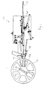
Figure 1 represents an automatic reel-coiling and changing device according to one aspect of the invention. It includes anupper magazine 70 in which theempty reels 25 waiting to be processed are loaded. The upper magazine is placed above thecoiling position 80 in which the reels are mounted on arotatable shaft 32 for coiling. Atape insertion unit 50 is placed at the same level as thecoiling position 80 and is used to automatically guide the tape leading section to the reel and affix it to the hub of the reel, as it will be explained later. -
Figure 4 illustrates, in a simplified schematic way, the automatic reel changing system of the invention. Theempty reels 25 in theupper magazine 70 are moved by the linear actuator 41 (for example an air cylinder, or a linear motor, or any other equivalent actuator) up to theaxis reference 42 The axis will be used as mechanical reference for the transfer of the roller from the upper magazine to the loading position. - Then a linear actuator 42 (for example an air cylinder, or a linear motor, or any other equivalent actuator) will move the
empty reel 25 through the opening 71 downwards until they are level with theshaft 32 at thecoiling position 80. The movement can be guided additional guiding elements like slides, roll or inclines (not represented) under the action of the gravity until it reaches the desired position. - At this point, the reel will be indexed by
reference guides 43, which can be activated by cylinders, motors or any other suitable mechanic actuator. Once thereel 23 is in the reference position, theshaft 32 of the reeler will be inserted within the centre of thereel 23. The engagement can be obtained in several ways, for example by a second, non represented linear actuator or, preferably, by a sideways displacement of theshaft 32. After theshaft 32 is inserted and coupled with the reel 23 amotor 39, or any other suitable actuator, drives it in rotation in order to fill the reel with the desired amount of flexible tape carrier. - Upon completion of the coiling operation, the
full reels 26 are disengaged from theshaft 32 and move downwards, under the action of linear actuator 45 (which could take the form, in different variants of the invention, of an air cylinder, linear motor or any equivalent actuator) into thelower magazine 90. The reels could also, in a variant of the invention fall down under the action of gravity through opening 81. In this case the fall of the reels can be slowed down and guided by appropriate means, when necessary. - In a non-illustrated variant of the invention, the reel in the
coiling position 80 is not rotatably mounted on a shaft, but is moved to a centre-less rotatable support, including one or more free rollers, and one or more driven rollers, interacting with the rim of the reel for supporting it and driving it in rotation (not represented here). - The function of the
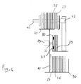
tape insertion unit 50 is now explained with reference tofigure 2 . Astraight guide 160 guides theflexible tape 60 towards thehub 29 of thereel 28. The part of the guide closer to the hub is composed by a lowersliding guide 128, actuated by theair cylinder 129, and by an upper articulatedjaw 125 that, when in operation, as shown infigure 2 , are closed one against the other, defining a channel for guiding the tape to thehub 29 without any deviation. When thereel 28 must be inserted or removed, the articulated jaw rotates upwards, and thesliding guide 128 moves backwards, as shown infigure 3a , so as to clear the reel and allow its insertion or removal. -
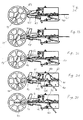
Figure 3a illustrates the beginning of a coiling operation, in which the leadingend 61 of thetape 60 is sliding along theguide 160 and is not yet close to thehub 29 of thewheel 28. In following steps, as shown infigure 3b , thejaw 125 and thesliding guide 128 are moved one against the other in order to provide a closed channel that guides thestrip 60 to thehub 29 without bending it. - Once the leading edge of the
strip 60 is sufficiently close to thehub 29, a vacuum is applied to a first restriction device 161 (fig. 3c ), in order to stop, or hinder, the forward motion of theflexible strip 60. Since the strip is continuously fed from behind, portion of the strip behind therestriction point 161 lifts from thestraight guide 160 forming aslack arc 61, as visible infigure 3c . -
Figure 3d illustrates a further stage of the reel change according to the method of the invention and shows that thearc 61 grows higher because thestrip 60 is continuously fed from the right. Theslack arc 61 is measured by the position sensor 261 that is arranged to detect when thearc 61 has reached a determined height. Once the desired height is attained forarc 61, asecond restriction device 162, placed upwards with respect to the first restriction device and the feeding direction of theflexible tape 60, is activated to stop or hinder the tape motion, whereby asecond arc 62 is formed in thetape 60 before thesecond restriction device 162. - The height of the
second art 62 is sensed byposition sensor 262. In a preferred variant,position sensors 261 and 262 are both mechanical switches. The invention however allows other type of position sensors, for example optical sensors, to sense the height ofarcs - The structure of
restriction devices first restriction device 161 is a vacuum suction plate, which has the advantage of not damaging or bending the leading end of the tape in any way. It is preferable, for an easy insertion in theslit 291 of the reel'shub 29, that the leading end should be kept very straight. Thesecond restriction device 162 is located further upwards, in a position at which small bends in the tape are acceptable, and is a mechanical clamp, operated by a piston, that presses the tape onto theunderlying guide 160. - The insertion unit of the invention preferably includes also a
moveable obstacle 165 that is lifted above thestraight guide 160 in order to assist the formation of thearc 62. In a simplified variant, theobstacle 165 could also be fixed. -
Figure 3e illustrates some last steps of the insertion process. Therestriction device 161 and then therestriction device 162 are deactivated, whereby the slack tape in the loops is released and the leading edge of the tape moves rapidly forward, and enters theslit 291 of the reel'shub 29. Preferably the angular position of thereel 29 is measured by a suitable sensor, and the deactivation of therestriction devices slit 291 in alignment with the leading edge of the tape. Though slotted hubs are almost universally used, it is conceivable that the invention could be used with different kinds of fixation features, for example a hook, a roller, a magnetic connection, or any suitable fixation. - Once the leading edge is inserted in the
slit 291, the coiling of thetape 60 in thereel 29 can proceed normally. Preferably, thejaw 125 and thelower guide 128 are retreated ad this moment, to leave space for the tape inside the reel. The speed of rotation of thereel 29 and/or the feeding speed of thetape 60 are preferably controlled so as to maintain a set height in thearcs detectors 261 and 262. In this manner the tape tension is minimal, even at high coiling speed, and is reduced the friction of the tape on the guide.
Claims (17)
- A device for the automatic coiling and/or uncoiling of a flexible tape (60) on reels (28) comprising:a coiling location (80) where a reel (28) can be rotatably connected to the device;a tape insertion unit (50), operatively arranged to guide the flexible tape (60) and connect a free end of the flexible (60) tape to a hub of the reel (28).
- The device of the previous claim, further comprising: a fist reel magazine (70) for stocking reels to be processed (25) and placed above the coiling location (80), a second reel magazine (90) for stocking the reels that have been processed (26) placed below the coiling location (80), the device being operatively arranged to move the reels to be processed (25) from the first magazine (70) towards the coiling location (80), coil the flexible tape (60) in the reels, and to move the processed reels (26) from the coiling location (80) to the second magazine (90), the motion of the reels from said first magazine (70) and/or to said second magazine (90) being driven or assisted by gravity.
- The device of the previous claim, further comprising a linear actuator (41), operatively arranged to connect the reels to be processed to the device in the coiling location (80).
- The device of any of the previous claims, further comprising a linear actuator (41) operatively arranged to move the reels to be processed (25) above a opening (71) in said first reel magazine (70), whereby the reels to be processed (25) move to the opening (71) in their motion towards the coiling location (80).
- The device of claim 1, including a driven rotatable shaft (32) onto which said reels can be rotatably mounted in the coiling location.
- The device of claim 1, including at least a driven roller interoperating with an outer rim of the reel to drive the reel in rotation.
- The device of claim 1 including one or more free rollers to rotatably support the reel in the coiling location.
- The device of any of the preceding claims, being so arranged that one or more sections of the flexible tape (60) assume the shape of arcs (61, 62), during a coiling operation.
- The device of the preceding claim, wherein the tape insertion unit contains one linear guide (160) and at least one restriction means (161, 162) that can be operated to stop or hinder the advance of at least a section of the flexible tape (60) and induce the formation of an arc (61, 62) behind the restriction means (161, 162), the arc being a self-supported slack portion of the tape (60) lifted from the linear guide (160).
- The device of claim 8, wherein the tape insertion unit includes two restriction means (161, 162) in succession that can be operated to hinder or stop the advance of at least two section of the flexible tape (60) and induce the formation of at least two arcs (61, 62) in the flexible tape (60).
- The device of one of the claims 8-9, wherein said restriction means consist in a mechanical clamp (162) or a vacuum suction device (161).
- The device of one of the claims 7-9, further comprising at least one position detector (261, 262) arranged to detect a height of at least one arc (61, 62) in the flexible tape (60).
- The device of the preceding claim, wherein said position detector (261, 262) is a mechanical switch.
- The device of any of the preceding claims, further comprising a fixed or moveable obstacle (165) under at least one arc section (61, 62) of the flexible tape (60).
- The device of any of the preceding claims, further comprising a sliding lower guide (128) and a hinged upper guide (125) operatively arranged to penetrate into the reel (28) toward the hub (29) of the reel and define a channel for the flexible tape (60), to assist its introduction in the reel (28) and its connexion with the hub (29).
- A method for coiling a flexible tape carrier (60) on a reel (28), said tape (60) comprising a leading end for engagement in the reel (28), the method comprising the steps of:feeding the flexible tape (60) towards the reel (28);stopping or hindering the advance of said leading end with a first restriction means (161) so as to produce a first slack arc portion (61) in the flexible tape (60);detecting when the first slack arc portion has reached a determined height;stopping or hindering the advance of one intermediary portion of tape with a second restriction means (62) while feeding the flexible tape further, so a to produce a second slack arc portion (62) of tape; detecting engagement of said leading end into a hub (29) of the reel (28) or alignment of said leading end with a fixation feature (291) of the hub (29) of the reel;releasing the restriction means (161, 162).
- The method of the previous claim, further comprising a step of detecting the height of said second slack arc portion.
Priority Applications (6)
| Application Number | Priority Date | Filing Date | Title |
|---|---|---|---|
| EP08172524A EP2187723A1 (en) | 2008-11-17 | 2008-12-22 | Auto reel changer |
| EP09780103A EP2351475B1 (en) | 2008-11-17 | 2009-07-02 | Auto reel changer |
| CN200980145561.8A CN102232324B (en) | 2008-11-17 | 2009-07-02 | Auto reel changer |
| MYPI2011001843A MY156506A (en) | 2008-11-17 | 2009-07-02 | Auto-reel changer |
| PCT/EP2009/058356 WO2010054865A1 (en) | 2008-11-17 | 2009-07-02 | Auto reel changer |
| US13/099,470 US8439292B2 (en) | 2008-11-17 | 2011-05-03 | Auto-reel changer |
Applications Claiming Priority (2)
| Application Number | Priority Date | Filing Date | Title |
|---|---|---|---|
| EP08169267 | 2008-11-17 | ||
| EP08172524A EP2187723A1 (en) | 2008-11-17 | 2008-12-22 | Auto reel changer |
Publications (1)
| Publication Number | Publication Date |
|---|---|
| EP2187723A1 true EP2187723A1 (en) | 2010-05-19 |
Family
ID=41479361
Family Applications (2)
| Application Number | Title | Priority Date | Filing Date |
|---|---|---|---|
| EP08172524A Withdrawn EP2187723A1 (en) | 2008-11-17 | 2008-12-22 | Auto reel changer |
| EP09780103A Not-in-force EP2351475B1 (en) | 2008-11-17 | 2009-07-02 | Auto reel changer |
Family Applications After (1)
| Application Number | Title | Priority Date | Filing Date |
|---|---|---|---|
| EP09780103A Not-in-force EP2351475B1 (en) | 2008-11-17 | 2009-07-02 | Auto reel changer |
Country Status (5)
| Country | Link |
|---|---|
| US (1) | US8439292B2 (en) |
| EP (2) | EP2187723A1 (en) |
| CN (1) | CN102232324B (en) |
| MY (1) | MY156506A (en) |
| WO (1) | WO2010054865A1 (en) |
Cited By (2)
| Publication number | Priority date | Publication date | Assignee | Title |
|---|---|---|---|---|
| CN110342308A (en) * | 2019-06-27 | 2019-10-18 | 江阴新基电子设备有限公司 | A kind of CD-ROM jukebox rewinding control method |
| CN112429564A (en) * | 2019-08-26 | 2021-03-02 | 英泰克普拉斯有限公司 | Automatic reel replacing system |
Families Citing this family (10)
| Publication number | Priority date | Publication date | Assignee | Title |
|---|---|---|---|---|
| WO2014047336A1 (en) | 2012-09-19 | 2014-03-27 | Kufre Akpan | Rear discharge mat rolling machine with wrapper |
| WO2016022074A1 (en) * | 2014-08-05 | 2016-02-11 | Semiconductor Technologies & Instruments Pte Ltd | Multiple tape reel handling apparatus |
| TWI542525B (en) * | 2015-06-02 | 2016-07-21 | All Ring Tech Co Ltd | Method and device for transporting tape for electronic component packaging |
| TWI541184B (en) * | 2015-06-02 | 2016-07-11 | All Ring Tech Co Ltd | Method and device for transporting tape for electronic component packaging |
| KR101886163B1 (en) * | 2016-09-02 | 2018-08-07 | (주)제이티 | Device handler, and carrier tape winding device therefor |
| CN106516825B (en) * | 2016-12-19 | 2018-04-24 | 江阴新基电子设备有限公司 | Carrier band feeding is taped device |
| CN111868905A (en) * | 2018-03-15 | 2020-10-30 | 巨友技术有限公司 | Automatic output reel converter |
| MY194779A (en) * | 2018-04-10 | 2022-12-15 | Mi Equipment M Sdn Bhd | System and method of replacing reel |
| CN112106458B (en) | 2018-06-27 | 2021-11-12 | 雅马哈发动机株式会社 | Component supply device |
| CN116588759B (en) * | 2022-11-04 | 2024-08-09 | 苏州正齐半导体设备有限公司 | Carrier tape inserting device and carrier tape inserting method |
Citations (2)
| Publication number | Priority date | Publication date | Assignee | Title |
|---|---|---|---|---|
| US4747553A (en) * | 1986-05-14 | 1988-05-31 | Fsk Corporation | Method and apparatus for taking up taping tape loaded with electronic parts therein |
| US20030094235A1 (en) * | 2001-06-07 | 2003-05-22 | Robotic Vision Systems, Inc. | Mulitple output reel taper apparatus having linear and push-out reel changer |
Family Cites Families (10)
| Publication number | Priority date | Publication date | Assignee | Title |
|---|---|---|---|---|
| DE1159757B (en) * | 1962-12-08 | 1963-12-19 | Bauer Eugen Gmbh | Automatic film threading device on cinematographic recording or playback devices |
| US3270974A (en) * | 1963-10-30 | 1966-09-06 | Eastman Kodak Co | Self-threading camera |
| DE2445998C3 (en) * | 1974-09-26 | 1982-01-14 | Agfa-Gevaert Ag, 5090 Leverkusen | Take-up device for strip-shaped material |
| US4604154A (en) * | 1983-11-28 | 1986-08-05 | Owens-Illinois, Inc. | Apparatus and method for guiding plastic labels to a label-wrapping station |
| JP3002684B2 (en) * | 1990-07-24 | 2000-01-24 | コニカ株式会社 | Film processing equipment |
| EP0543069B1 (en) * | 1991-11-20 | 1996-07-31 | Gretag Imaging Ag | Photographic printer and method of operation |
| DE4204340A1 (en) * | 1992-02-11 | 1993-08-12 | Mannesmann Ag | RECORDING CASSETTE FOR RAILWAY MATERIAL, ESPECIALLY FOR AN EXPOSED FILM RAIL |
| MY112708A (en) | 1993-09-07 | 2001-08-30 | Lintec Corp | Tape winding apparatus and tape |
| DE69522983T2 (en) * | 1994-03-30 | 2002-04-04 | Noritsu Koki Co., Ltd. | Device for the continuous recording of film material |
| US6123286A (en) * | 1998-12-16 | 2000-09-26 | Kemet Corporation | Apparatus for winding a carrier tape |
-
2008
- 2008-12-22 EP EP08172524A patent/EP2187723A1/en not_active Withdrawn
-
2009
- 2009-07-02 EP EP09780103A patent/EP2351475B1/en not_active Not-in-force
- 2009-07-02 CN CN200980145561.8A patent/CN102232324B/en not_active Expired - Fee Related
- 2009-07-02 MY MYPI2011001843A patent/MY156506A/en unknown
- 2009-07-02 WO PCT/EP2009/058356 patent/WO2010054865A1/en active Application Filing
-
2011
- 2011-05-03 US US13/099,470 patent/US8439292B2/en not_active Expired - Fee Related
Patent Citations (2)
| Publication number | Priority date | Publication date | Assignee | Title |
|---|---|---|---|---|
| US4747553A (en) * | 1986-05-14 | 1988-05-31 | Fsk Corporation | Method and apparatus for taking up taping tape loaded with electronic parts therein |
| US20030094235A1 (en) * | 2001-06-07 | 2003-05-22 | Robotic Vision Systems, Inc. | Mulitple output reel taper apparatus having linear and push-out reel changer |
Cited By (3)
| Publication number | Priority date | Publication date | Assignee | Title |
|---|---|---|---|---|
| CN110342308A (en) * | 2019-06-27 | 2019-10-18 | 江阴新基电子设备有限公司 | A kind of CD-ROM jukebox rewinding control method |
| CN112429564A (en) * | 2019-08-26 | 2021-03-02 | 英泰克普拉斯有限公司 | Automatic reel replacing system |
| CN112429564B (en) * | 2019-08-26 | 2023-10-13 | 英泰克普拉斯有限公司 | Automatic reel replacement system |
Also Published As
| Publication number | Publication date |
|---|---|
| EP2351475A1 (en) | 2011-08-03 |
| WO2010054865A1 (en) | 2010-05-20 |
| US8439292B2 (en) | 2013-05-14 |
| CN102232324A (en) | 2011-11-02 |
| US20110220755A1 (en) | 2011-09-15 |
| MY156506A (en) | 2016-02-26 |
| CN102232324B (en) | 2014-07-23 |
| EP2351475B1 (en) | 2013-01-02 |
Similar Documents
| Publication | Publication Date | Title |
|---|---|---|
| EP2187723A1 (en) | Auto reel changer | |
| EP1655225B1 (en) | A method and an apparatus for automatic change of the reel of extensible film in wrapping machines for the packaging of palletized loads | |
| US8015781B2 (en) | Box loader | |
| TWI759473B (en) | Wind-up system and method for winding-up a strip | |
| RU2005131611A (en) | AUTOMATIC RELEASE DEVICE FOR CONTINUOUS ACTION FOR SUBMITTING MATERIAL AS A TAPE FROM COILS | |
| JP2015506320A5 (en) | ||
| WO2009040749A2 (en) | Method of and apparatus for producing long, assembled, electric cables | |
| EP2072440B1 (en) | Unwinding assisting device and method for operating an unwinding assisting device | |
| CN116216384A (en) | Automatic winding and unwinding device for SMT (surface mounted technology) material disc | |
| CN104206049B (en) | Carrier equipment, system and method for processing component band | |
| CA2562394C (en) | Method and assembly for transferring rolls during packaging | |
| EP3574231B1 (en) | Dispenser for coil adhesive weights with dual loading system | |
| JP4582525B2 (en) | Component placement device | |
| SE407395B (en) | DEVICE FOR RECEIVING DRINKS OF LINEN GOODS | |
| CN216035587U (en) | Automatic belt winding and binding machine | |
| EP0492388B1 (en) | Method and apparatus for winding and storing tape-like article in container | |
| CN110127350B (en) | Automatic feeding and discharging mechanism | |
| TWI729296B (en) | Tape delivery device and tape delivery method | |
| US20210020474A1 (en) | Automatic output reel changer | |
| TWI508636B (en) | Auto-reel changer | |
| CN113716156B (en) | Automatic belt winding and binding machine | |
| CN218366606U (en) | Unwinding system for unwinding tyre components from a magazine reel | |
| EP0659675A1 (en) | Device for loading and unloading cops in textile winding apparatus | |
| EP0471133B1 (en) | Apparatus for picking up and guiding in a predetermined path a magnetic tape wound onto a reel in automatic cassette loading machines | |
| JP2757530B2 (en) | Method for arranging sliver ends in spinning machine |
Legal Events
| Date | Code | Title | Description |
|---|---|---|---|
| PUAI | Public reference made under article 153(3) epc to a published international application that has entered the european phase |
Free format text: ORIGINAL CODE: 0009012 |
|
| AK | Designated contracting states |
Kind code of ref document: A1 Designated state(s): AT BE BG CH CY CZ DE DK EE ES FI FR GB GR HR HU IE IS IT LI LT LU LV MC MT NL NO PL PT RO SE SI SK TR |
|
| AX | Request for extension of the european patent |
Extension state: AL BA MK RS |
|
| AKY | No designation fees paid | ||
| REG | Reference to a national code |
Ref country code: DE Ref legal event code: 8566 |
|
| STAA | Information on the status of an ep patent application or granted ep patent |
Free format text: STATUS: THE APPLICATION IS DEEMED TO BE WITHDRAWN |
|
| 18D | Application deemed to be withdrawn |
Effective date: 20101120 |