EP2186959A2 - T-connection between a profiled post and profiled transom - Google Patents
T-connection between a profiled post and profiled transom Download PDFInfo
- Publication number
- EP2186959A2 EP2186959A2 EP09175104A EP09175104A EP2186959A2 EP 2186959 A2 EP2186959 A2 EP 2186959A2 EP 09175104 A EP09175104 A EP 09175104A EP 09175104 A EP09175104 A EP 09175104A EP 2186959 A2 EP2186959 A2 EP 2186959A2
- Authority
- EP
- European Patent Office
- Prior art keywords
- profile
- locking
- connecting element
- transom
- connection according
- Prior art date
- Legal status (The legal status is an assumption and is not a legal conclusion. Google has not performed a legal analysis and makes no representation as to the accuracy of the status listed.)
- Granted
Links
- 238000010276 construction Methods 0.000 claims description 9
- 230000013011 mating Effects 0.000 claims description 4
- 239000011796 hollow space material Substances 0.000 abstract description 2
- 238000006073 displacement reaction Methods 0.000 description 4
- XAGFODPZIPBFFR-UHFFFAOYSA-N aluminium Chemical compound [Al] XAGFODPZIPBFFR-UHFFFAOYSA-N 0.000 description 1
- 229910052782 aluminium Inorganic materials 0.000 description 1
- 239000002131 composite material Substances 0.000 description 1
- 230000001419 dependent effect Effects 0.000 description 1
- 238000011161 development Methods 0.000 description 1
- 230000018109 developmental process Effects 0.000 description 1
- 239000011521 glass Substances 0.000 description 1
- 230000014759 maintenance of location Effects 0.000 description 1
- 238000003801 milling Methods 0.000 description 1
- 238000004080 punching Methods 0.000 description 1
Images


Classifications
-
- E—FIXED CONSTRUCTIONS
- E04—BUILDING
- E04B—GENERAL BUILDING CONSTRUCTIONS; WALLS, e.g. PARTITIONS; ROOFS; FLOORS; CEILINGS; INSULATION OR OTHER PROTECTION OF BUILDINGS
- E04B2/00—Walls, e.g. partitions, for buildings; Wall construction with regard to insulation; Connections specially adapted to walls
- E04B2/88—Curtain walls
- E04B2/96—Curtain walls comprising panels attached to the structure through mullions or transoms
- E04B2/965—Connections of mullions and transoms
Definitions
- the invention relates to a T-joint between a mullion and a transom profile, in particular for mullion and transom constructions of facades, skylights and conservatories, according to the preamble of claim 1.
- the invention also relates to a mullion-transom construction, in which at right angles mutually arranged mullion and transom profiles are interconnected by a T-connection.
- T-connection is from the EP 1 491 696 A2 known.
- the one holding means is designed as a profile piece with receiving channels for screws or other fastening means.
- the serving for supporting second holding means in as a screw, rivet, pin or bolt designed to engage in a semi-circular recording.
- the attachment of the locking bar profile on the post is done by screws, which are screwed from the outside of the locking bar transverse to its longitudinal direction through corresponding holes in the designed as a profile piece first holding means.
- the provided for this purpose in the bolt profile holes for receiving the screws are offset with respect to the holes in the profile piece, so that when screwing together a contact pressure of the bar profile results in the post profile. At the serving for supporting second holding means, however, no protection against displacement of the bolt profiles in the longitudinal direction is provided.
- the object of the invention is to provide a T-connection of the type mentioned and a mullion-transom construction with such a T-connection, which allows in a simple and cost-effective manner secured against displacement connection between a mullion and transom profile.
- the connecting element which can be fastened to the outside of the post profile and engages in a cavity of the locking profile has a locking projection for engagement in a corresponding recess in a web within the locking profile.
- the locking lug has a locking bevel for abutment with a mating surface of the web.
- the bolt profile can be pressed at a lateral displacement of the outer surface of the post profile, so that there is a gap-free and against leveraging particularly well secured positive connection between the post and bolt profile.
- the recess for the locking lug can e.g. be arranged in a single or two mutually parallel lateral webs within the transom profile.
- the recess may also be arranged in a transverse web which extends between two lateral webs arranged within the hollow space of the bolt profile.
- the dimensions of the connecting element and of the channel are advantageously matched to one another in such a way that the width of the connecting element substantially corresponds to the width of the channel defined by the distance between the two lateral webs and the height of the connecting element to the locking projection is slightly less than the height of the channel is.
- the locking profile can be pushed onto the connecting element and the connecting element lies with its side surfaces on the inner sides of the On the canal. By investing the side surfaces a positive retention of the bar profile is achieved up and down.
- a mullion and transom construction according to the invention contains at right angles interconnected mullion and transom profiles, which are connected to one another by a T-connection described above and described in more detail below.
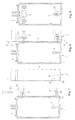
- FIGS. 1 to 3 is a first embodiment of a T-connection between a post profile 1 and a locking profile 2 before assembly, in the assembled State and shown in a sectional view.
- the two mullion and transom sections 1 and 2 have the same or different cross-sections and consist of a support profile 3, for example made of extruded aluminum, the two parallel longer outer sides 4, two perpendicular shorter outer sides 5, a cavity 6 and one of a short outside 5 centrally protruding fastening web 7 with a mounting channel 8 contains.
- Right and left of the mounting web 7 5 parallel two holding webs 9 are provided for mounting a designed as a profile seal inner seal on the outside.
- the support section 3 also has a running in the longitudinal direction of the support section 3 channel 10, which is bounded by two spaced, parallel side webs 11 and a web 12 extending transversely thereto.
- the lateral webs 11 are arranged parallel to the outer sides 4 and protrude from a curious inner wall of the support section 3 in the cavity 6 in it.
- the support profiles 3 which can be used both as a post profile 1 and as a locking profile 2 are connected at right angles to each other for producing a post-and-beam construction for facades, conservatories, skylights and the like via connecting elements 13 and 14 explained in more detail below.
- the connecting elements 13 and 14 are fixed to the bolt profile 2 facing outside 4 of the post profile 1 and engage in the cavity 6 at the post profile 1 facing end face 15 of the bar profile 2 a.
- This in FIG. 1 shown below, for example, is fastened via a screw 16 or other suitable fastener on the outside 5 of the post profile 1 and engages in the limited by the webs 11 and 12 channel 10 within the cavity 6 of the bar profile 2 a.
- the connecting element 13 is designed as a molded part with a locking lug 17 for engagement in a recess 18 in the web 12 of the locking profile 2.
- the recess 18 can be made, for example, by punching or milling the web 12 in the locking profile 2, wherein the recess 18 is set back relative to the front side 15 of the locking bar profile 2 inside and on the front side 15 of the locking bar 2 a remainder piece 19 of the web 12 remains.
- the locking lug 17 has a locking bevel 20 for engaging an in FIG. 2 shown mating surface 21 on the remainder piece 19 of the web 12.
- the dimensions of the inner connecting element 13 and the channel 10 are matched to one another such that the in FIG. 3 recognizable width X of the connecting element 13th corresponds to the width x of the limited by the webs 11 and 12 channel 10 and the in FIG. 1 recognizable height H of the connecting element 13 with the locking lug 17 is slightly less than the height h of the channel 10.
- the locking profile 2 can be pushed onto the connecting element 13 and abuts with its side surfaces on the inner sides of the channel 10. By the plant of the side surfaces a holder of the bar profile 2 is reached up and down.
- the outer connecting element 14 may be formed as a matched to the inner contour of the locking bar 2 profile piece and is also secured by screws 22 or other fasteners on the outer wall 4 of the post section 1.
- the outer connecting element 14 has two in FIG. 3 recognizable screw 24 on.
- the locking profile 2 can be fastened via one or more retaining screws 25 arranged transversely to the longitudinal direction of the locking profile and screwed in through the front side of the locking profile 2.
- the connecting element 14 may for this purpose have corresponding screw channels, recesses or holes for receiving the retaining screws 25.
- the latch profile 2 with the recess 18 relative to the mullion profile 1 initially so in the direction of the mounting web 7 offset forward on the two connecting elements 13 and 14 plugged that the locking lug 17th can engage in the channel 10 on the front side 15 of the latch profile 2. If then the retaining screw 25 is screwed and tightened in the outer connecting element 14, the locking profile 2 is displaced so that the locking lug 17 engages in the recess 18 and the locking profile 2 is pressed over the locking slope 20 to the outer surface of the mullion profile 1. As a result, a gap-free and firm connection between the mullion and transom profile is achieved.
- FIGS. 4 to 6 is a second embodiment of a T-joint between a post profile 1 and a bolt profile 2 shown before assembly, in the assembled state and in a sectional view.
- the support profiles 3 in this embodiment essentially correspond to the support profiles of the first exemplary embodiment, so that components corresponding to one another are not explained or designated in any more detail.
- the two of a short inner wall of the support section 3 projecting into the cavity 6, parallel webs 11 are not connected to each other by a transverse web.
- 11 slots 26 are each provided with the recesses 18 for engagement of the locking lug 17 on the front side 15 of the locking bar profile 2 in the two lateral webs 11.
- the recesses 18 in the two webs 11 are here designed as an upper recess within the slots 26 with an oblique mating surface 21 for abutment of the locking bevel 20 on the locking lug 17.
- the connecting element 13 used here has a greater width X than the distance between the two webs, so that the connecting element 13 protrudes laterally relative to the two webs 11, as is apparent from FIG. 6 is apparent. Otherwise, the two connecting elements 13 and 14 are executed as in the first embodiment.
- FIGS. 7 to 9 illustrated third embodiment only a single web 11 is provided with a corresponding recess 18 for engagement of the locking lug 17.
- the recess is designed as an upper recess within a slot 26 in the web 11.
- the locking lug 17 here no locking slope.
Abstract
Description
Die Erfindung betrifft eine T-Verbindung zwischen einem Pfosten- und einem Riegelprofil, insbesondere für Pfosten-Riegel-Konstruktionen von Fassaden, Lichtdächern und Wintergärten, nach dem Oberbegriff des Anspruchs 1. Die Erfindung betrifft außerdem eine Pfosten-Riegel-Konstruktion, bei der rechtwinklig zueinander angeordnete Pfosten- und Riegelprofile durch eine T-Verbindung miteinander verbunden sind.The invention relates to a T-joint between a mullion and a transom profile, in particular for mullion and transom constructions of facades, skylights and conservatories, according to the preamble of
Eine derartige T-Verbindung ist aus der
Aufgabe der Erfindung ist es, eine T-Verbindung der eingangs genannten Art und eine Pfosten-Riegel-Konstruktion mit einer solchen T-Verbindung zu schaffen, die auf einfache und kostengünstige Weise eine gegen Verschieben gesicherte Verbindung zwischen einem Pfosten- und Riegelprofil ermöglicht.The object of the invention is to provide a T-connection of the type mentioned and a mullion-transom construction with such a T-connection, which allows in a simple and cost-effective manner secured against displacement connection between a mullion and transom profile.
Diese Aufgabe wird durch eine T-Verbindung mit den Merkmalen des Anspruchs 1 und durch eine Pfosten-Riegel-Konstruktion mit den Merkmalen des Anspruchs 11 gelöst. Zweckmäßige Weiterbildungen und vorteilhafte Ausfiihrungsformen der Erfindung sind Gegenstand der Unteransprüche.This object is achieved by a T-connection with the features of
Bei der erfindungsgemäßen T-Verbindung weist das an der Außenseite des Pfostenprofils befestigbare und in einen Hohlraum des Riegelprofils eingreifende Verbindungselement einen Verriegelungsansatz zum Eingriff in eine entsprechende Ausnehmung in einem Steg innerhalb des Riegelprofils auf. Durch den Verriegelungsansatz kann auf relativ einfache und kostengünstige Weise eine zusätzliche und von außen unsichtbare Sicherung des Riegelprofils gegen Verschiebung in dessen Längsrichtung erreicht werden. Dadurch kann z.B. verhindert werden, dass das Riegelprofil beim Transport einer aus Pfosten- und Riegelprofilen hergestellten Fassadenkonstruktion im Bereich des Verbindungselements ausgehebelt wird oder in diesem Bereich eine Fuge zwischen dem Pfosten- und Riegelprofil entsteht.In the case of the T-connection according to the invention, the connecting element which can be fastened to the outside of the post profile and engages in a cavity of the locking profile has a locking projection for engagement in a corresponding recess in a web within the locking profile. By locking approach can be achieved in a relatively simple and cost-effective manner an additional and invisible from the outside securing the locking bar against displacement in the longitudinal direction. Thereby, e.g. be prevented that the bolt profile is levered out during transport of a facade construction made of post and beam profiles in the region of the connecting element or in this area, a gap between the mullion and transom profile is formed.
In einer besonders zweckmäßigen Ausführung weist der Verriegelungsansatz eine Verriegelungsschräge zur Anlage an einer Gegenfläche des Stegs auf. Über die Verriegelungsschräge am Verriegelungsansatz kann das Riegelprofil bei einer seitlichen Verschiebung an die Außenfläche des Pfostenprofils angedrückt werden, so dass sich eine spaltfreie und gegen Aushebeln besonders gut gesicherte formschlüssige Verbindung zwischen dem Pfosten- und Riegelprofil ergibt.In a particularly advantageous embodiment, the locking lug has a locking bevel for abutment with a mating surface of the web. About the locking slope on the locking lug, the bolt profile can be pressed at a lateral displacement of the outer surface of the post profile, so that there is a gap-free and against leveraging particularly well secured positive connection between the post and bolt profile.
Die Ausnehmung für den Verriegelungsansatz kann z.B. in einem einzelnen oder zwei zueinander parallelen seitlichen Stegen innerhalb des Riegelprofils angeordnet sein. Die Ausnehmung kann aber auch in einen Quersteg angeordnet sein, der zwischen zwei innerhalb des Hohlraums des Riegelprofils angeordneten seitlichen Stegen verläuft. Durch die beiden seitlichen Stege und den quer dazu verlaufenden Steg für die Ausnehmung kann zweckmäßigerweise ein Kanal zur Aufnahme des Verbindungselements begrenzt werden.The recess for the locking lug can e.g. be arranged in a single or two mutually parallel lateral webs within the transom profile. However, the recess may also be arranged in a transverse web which extends between two lateral webs arranged within the hollow space of the bolt profile. By the two lateral webs and the transverse thereto extending web for the recess a channel for receiving the connecting element can be limited expediently.
Die Abmessungen des Verbindungselements und des Kanals sind in vorteilhafter Weise derart aufeinander abgestimmt, dass die Breite des Verbindungselements im Wesentlichen der durch den Abstand zwischen den beiden Seitenstegen vorgegeben Breite des Kanals entspricht und die Höhe des Verbindungselements mit dem Verriegelungsansatz etwas geringer als die Höhe des Kanals ist. Dadurch kann das Riegelprofil auf das Verbindungselement aufgeschoben werden und das Verbindungselement liegt mit seinen Seitenflächen an den Innenseiten des Kanals an. Durch die Anlage der Seitenflächen wird eine formschlüssige Halterung des Riegelprofils nach oben und unten erreicht.The dimensions of the connecting element and of the channel are advantageously matched to one another in such a way that the width of the connecting element substantially corresponds to the width of the channel defined by the distance between the two lateral webs and the height of the connecting element to the locking projection is slightly less than the height of the channel is. As a result, the locking profile can be pushed onto the connecting element and the connecting element lies with its side surfaces on the inner sides of the On the canal. By investing the side surfaces a positive retention of the bar profile is achieved up and down.
Eine erfindungsgemäße Pfosten-Riegel-Konstruktion enthält rechtwinklig miteinander verbundene Pfosten- und Riegelprofile, die durch eine vorstehend erläuterte und im Folgenden noch näher beschriebene T-Verbindung miteinander verbunden sind.A mullion and transom construction according to the invention contains at right angles interconnected mullion and transom profiles, which are connected to one another by a T-connection described above and described in more detail below.
Weitere Besonderheiten und Vorzüge der Erfindung ergeben sich aus der folgenden Beschreibung eines bevorzugten Ausführungsbeispiels anhand der Zeichnung. Es zeigen:
-
Figur 1 - ein erstes Ausführungsbeispiel einer T-Verbindung vor dem Zusammenbau;
-
Figur 2 - das erste Ausführungsbeispiel der T-Verbindung im zusammengesetzten Zustand;
- Figur 3
- eine Ansicht entlang der Linie A-A von
Figur 2 - Figur 4
- ein zweites Ausführungsbeispiel einer T-Verbindung vor dem Zusammenbau;
-
Figur 5 - das zweite Ausführungsbeispiel der T-Verbindung im zusammengesetzten Zustand;
-
Figur 6 - eine Ansicht entlang der Linie A-A von
Figur 5 -
Figur 7 - ein drittes Ausführungsbeispiel einer T-Verbindung vor dem Zusammenbau;
-
Figur 8 - das dritte Ausführungsbeispiel der T-Verbindung im zusammengesetzten Zustand und
- Figur 9
- eine Ansicht entlang der Linie A-A von
Figur 8
- FIG. 1
- a first embodiment of a T-connection before assembly;
- FIG. 2
- the first embodiment of the T-joint in the assembled state;
- FIG. 3
- a view along the line AA of
FIG. 2 ; - FIG. 4
- a second embodiment of a T-joint before assembly;
- FIG. 5
- the second embodiment of the T-joint in the assembled state;
- FIG. 6
- a view along the line AA of
FIG. 5 ; - FIG. 7
- a third embodiment of a T-junction before assembly;
- FIG. 8
- the third embodiment of the T-junction in the assembled state and
- FIG. 9
- a view along the line AA of
FIG. 8 ;
In den
Die sowohl als Pfostenprofil 1 als auch als Riegelprofil 2 einsetzbaren Tragprofile 3 sind zur Herstellung einer Pfosten-Riegel-Konstruktion für Fassaden, Wintergärten, Lichtdächer und dgl. über im Folgenden noch näher erläuterte Verbindungselemente 13 und 14 rechtwinklig miteinander verbunden. Hierzu sind die Verbindungselemente 13 und 14 an der zum Riegelprofil 2 weisenden Außenseite 4 des Pfostenprofils 1 befestigt und greifen in den Hohlraum 6 an der dem Pfostenprofil 1 zugewandten Stirnseite 15 des Riegelprofils 2 ein. Das in
Wie aus
Das in den
Bei der Verbindung eines Pfosten- und Riegelprofils mit der vorstehend beschriebenen T-Verbindung wird das Riegelprofil 2 mit der Ausnehmung 18 gegenüber dem Pfostenprofil 1 zunächst derart in Richtung des Befestigungsstegs 7 nach vorne versetzt auf die beiden Verbindungselemente 13 und 14 aufgesteckt, dass der Verriegelungsansatz 17 in den Kanal 10 an der Stirnseite 15 des Riegelprofils 2 eingreifen kann. Wenn dann die Halteschraube 25 in das äußere Verbindungselement 14 eingedreht und angezogen wird, wird auch das Riegelprofil 2 so verschoben, dass der Verriegelungsansatz 17 in die Ausnehmung 18 eingreift und das Riegelprofil 2 über die Verriegelungsschräge 20 an die Außenfläche des Pfostenprofils 1 angepresst wird. Dadurch wird eine spaltfreie und feste Verbindung zwischen dem Pfosten- und Riegelprofil erreicht.When connecting a mullion and transom profile with the T-connection described above, the
Über den vorstehenden Befestigungssteg 7 mit einer inneren Dichtung sowie ein als Pressleiste ausgebildetes Halteprofil mit äußeren Dichtungen sind an den Tragprofilen 3 z.B. als Isolierglasscheiben ausgeführte Fassadenelemente in an sich bekannter Weise abgedichtet befestigbar. Das als Pressleiste ausgeführte Halteprofil wird hierzu über in den Befestigungskanal 8 eingreifende Schrauben an dem Tragprofil 3 befestigt.About the
In den
Bei dem in den
Claims (11)
Applications Claiming Priority (1)
| Application Number | Priority Date | Filing Date | Title |
|---|---|---|---|
| DE202008014975U DE202008014975U1 (en) | 2008-11-12 | 2008-11-12 | T-connection between a mullion and transom profile |
Publications (3)
| Publication Number | Publication Date |
|---|---|
| EP2186959A2 true EP2186959A2 (en) | 2010-05-19 |
| EP2186959A3 EP2186959A3 (en) | 2012-06-27 |
| EP2186959B1 EP2186959B1 (en) | 2014-03-05 |
Family
ID=41508178
Family Applications (1)
| Application Number | Title | Priority Date | Filing Date |
|---|---|---|---|
| EP20090175104 Active EP2186959B1 (en) | 2008-11-12 | 2009-11-05 | T-connection between a profiled post and profiled transom |
Country Status (2)
| Country | Link |
|---|---|
| EP (1) | EP2186959B1 (en) |
| DE (1) | DE202008014975U1 (en) |
Families Citing this family (3)
| Publication number | Priority date | Publication date | Assignee | Title |
|---|---|---|---|---|
| DE202011051663U1 (en) * | 2011-10-18 | 2011-11-09 | Horst Filipp Gmbh | frame construction |
| DE102020103627B4 (en) | 2019-02-14 | 2023-10-12 | HUECK System GmbH & Co. KG | SPRING PIN BUTTON CONNECTOR |
| DE102020132662A1 (en) | 2020-12-08 | 2022-06-09 | Raico Bautechnik Gmbh | T-connection for mullion-transom constructions and mullion-transom construction with such a T-connection |
Citations (1)
| Publication number | Priority date | Publication date | Assignee | Title |
|---|---|---|---|---|
| EP1491696A2 (en) | 2003-06-06 | 2004-12-29 | Raico Bautechnik GmbH | System for joining profiles |
Family Cites Families (8)
| Publication number | Priority date | Publication date | Assignee | Title |
|---|---|---|---|---|
| DE3809951A1 (en) * | 1988-03-24 | 1989-10-05 | Schueco Int Gmbh & Co | T-CONNECTION BETWEEN TWO PROFILES, PREFERABLY A RUNG AND A POST PROFILE OF A FACADE |
| IT230412Y1 (en) * | 1993-09-17 | 1999-06-07 | Alumix Spa | TEAM CONNECTION STRUCTURE FOR THE RIGHT ANGLE JOINT OF METAL PROFILES FOR WINDOWS, FRAMES AND SIMILAR STRUCTURES |
| DE19849152C5 (en) * | 1998-10-26 | 2013-10-10 | Gutmann Ag | Post and rail connection |
| DE19901775A1 (en) * | 1999-01-18 | 2000-07-20 | Schueco Int Kg | T-connection between a rung and a mullion profile of a facade or a light roof |
| DE29910027U1 (en) * | 1999-06-09 | 1999-07-29 | Goetz Metall Anlagen | Mullion and transom system for building facades with infills |
| DE102004014598B4 (en) * | 2004-03-23 | 2006-07-27 | Thyssen Schulte Gutmann Bausysteme Gmbh | Butt connector for connecting profiles |
| DE202005000629U1 (en) * | 2005-01-15 | 2006-05-24 | SCHÜCO International KG | T-connector for a truss structure formed from post and transversely extending bar profiles |
| DE102005044980B4 (en) * | 2005-09-20 | 2010-06-02 | Hermann Gutmann Werke Ag | Butt connector for wood / aluminum facades |
-
2008
- 2008-11-12 DE DE202008014975U patent/DE202008014975U1/en not_active Expired - Lifetime
-
2009
- 2009-11-05 EP EP20090175104 patent/EP2186959B1/en active Active
Patent Citations (1)
| Publication number | Priority date | Publication date | Assignee | Title |
|---|---|---|---|---|
| EP1491696A2 (en) | 2003-06-06 | 2004-12-29 | Raico Bautechnik GmbH | System for joining profiles |
Also Published As
| Publication number | Publication date |
|---|---|
| EP2186959A3 (en) | 2012-06-27 |
| EP2186959B1 (en) | 2014-03-05 |
| DE202008014975U1 (en) | 2010-04-01 |
Similar Documents
| Publication | Publication Date | Title |
|---|---|---|
| EP1352134B1 (en) | Transom-mullion structure | |
| DE102005044980B4 (en) | Butt connector for wood / aluminum facades | |
| DE19849152C5 (en) | Post and rail connection | |
| EP1840315B1 (en) | Frame construction | |
| EP1580344A2 (en) | Butt joint for angular connection of hollow profiles, particularly for windows, doors and the like | |
| EP2186959B1 (en) | T-connection between a profiled post and profiled transom | |
| EP0722023A2 (en) | Uprights and transoms made of sectional bars connected together | |
| EP1840314B1 (en) | Fire resistant construction element | |
| EP1635075B1 (en) | Connection device | |
| EP1098046B1 (en) | Cladding system for building walls and roofs | |
| EP3879043A1 (en) | Sealing piece for sealing a t-connection between a post and latch profile and a post-latch structure with such a sealing piece | |
| EP3889384A1 (en) | Extruded window or door hollow section profile, system with such a hollow section profile and frame made from same | |
| DE19513623A1 (en) | Building facade glazing suspension | |
| DE3603221A1 (en) | Composite profile made up of individual profiles | |
| CH682344A5 (en) | ||
| EP1342861B1 (en) | Connection device | |
| DE102020106891B4 (en) | T-connection between a mullion and transom profile and a mullion-transom construction with such a T-connection | |
| EP4012132B1 (en) | T-connection for post-beam structure and a post-beam structure with such a t-connection | |
| EP2378045A2 (en) | Insulating glass panes | |
| DE102020111612B4 (en) | CONNECTOR ARRANGEMENT FOR THE ANGLED CONNECTION OF HOLLOW PROFILES, EACH OF ONE CONNECTION PROFILE AND A POSITION PROFILE, AND A PROFILE ARRANGEMENT WITH SUCH A CONNECTOR ARRANGEMENT | |
| DE10229272A1 (en) | Butt connector for angled connection of hollow profiles such as facades, roofs, windows and suchlike has holding element fastened to connecting section and with fixing pin which as material forming is component part of holding element | |
| EP1491696A2 (en) | System for joining profiles | |
| DE10043444B4 (en) | Window or door frame with a bolted connector | |
| DE3744223C1 (en) | Bulletproof frame leg | |
| DE102005001801A1 (en) | Joint connector for e.g. facades, has spring unit inserted between outer wall of holding unit and inner wall of horizontal latch insertion profile, where inner wall lies opposite to outer wall |
Legal Events
| Date | Code | Title | Description |
|---|---|---|---|
| PUAI | Public reference made under article 153(3) epc to a published international application that has entered the european phase |
Free format text: ORIGINAL CODE: 0009012 |
|
| AK | Designated contracting states |
Kind code of ref document: A2 Designated state(s): AT BE BG CH CY CZ DE DK EE ES FI FR GB GR HR HU IE IS IT LI LT LU LV MC MK MT NL NO PL PT RO SE SI SK SM TR |
|
| AX | Request for extension of the european patent |
Extension state: AL BA RS |
|
| PUAL | Search report despatched |
Free format text: ORIGINAL CODE: 0009013 |
|
| AK | Designated contracting states |
Kind code of ref document: A3 Designated state(s): AT BE BG CH CY CZ DE DK EE ES FI FR GB GR HR HU IE IS IT LI LT LU LV MC MK MT NL NO PL PT RO SE SI SK SM TR |
|
| AX | Request for extension of the european patent |
Extension state: AL BA RS |
|
| RIC1 | Information provided on ipc code assigned before grant |
Ipc: E04B 2/96 20060101AFI20120518BHEP |
|
| 17P | Request for examination filed |
Effective date: 20121130 |
|
| GRAP | Despatch of communication of intention to grant a patent |
Free format text: ORIGINAL CODE: EPIDOSNIGR1 |
|
| DAX | Request for extension of the european patent (deleted) | ||
| INTG | Intention to grant announced |
Effective date: 20131022 |
|
| GRAS | Grant fee paid |
Free format text: ORIGINAL CODE: EPIDOSNIGR3 |
|
| GRAA | (expected) grant |
Free format text: ORIGINAL CODE: 0009210 |
|
| AK | Designated contracting states |
Kind code of ref document: B1 Designated state(s): AT BE BG CH CY CZ DE DK EE ES FI FR GB GR HR HU IE IS IT LI LT LU LV MC MK MT NL NO PL PT RO SE SI SK SM TR |
|
| REG | Reference to a national code |
Ref country code: GB Ref legal event code: FG4D Free format text: NOT ENGLISH |
|
| REG | Reference to a national code |
Ref country code: CH Ref legal event code: EP Ref country code: CH Ref legal event code: NV Representative=s name: LUCHS AND PARTNER AG PATENTANWAELTE, CH |
|
| REG | Reference to a national code |
Ref country code: AT Ref legal event code: REF Ref document number: 654996 Country of ref document: AT Kind code of ref document: T Effective date: 20140315 |
|
| REG | Reference to a national code |
Ref country code: IE Ref legal event code: FG4D Free format text: LANGUAGE OF EP DOCUMENT: GERMAN |
|
| REG | Reference to a national code |
Ref country code: DE Ref legal event code: R096 Ref document number: 502009008920 Country of ref document: DE Effective date: 20140417 |
|
| REG | Reference to a national code |
Ref country code: NL Ref legal event code: VDEP Effective date: 20140305 |
|
| PG25 | Lapsed in a contracting state [announced via postgrant information from national office to epo] |
Ref country code: LT Free format text: LAPSE BECAUSE OF FAILURE TO SUBMIT A TRANSLATION OF THE DESCRIPTION OR TO PAY THE FEE WITHIN THE PRESCRIBED TIME-LIMIT Effective date: 20140305 Ref country code: NO Free format text: LAPSE BECAUSE OF FAILURE TO SUBMIT A TRANSLATION OF THE DESCRIPTION OR TO PAY THE FEE WITHIN THE PRESCRIBED TIME-LIMIT Effective date: 20140605 |
|
| REG | Reference to a national code |
Ref country code: LT Ref legal event code: MG4D |
|
| PG25 | Lapsed in a contracting state [announced via postgrant information from national office to epo] |
Ref country code: CY Free format text: LAPSE BECAUSE OF FAILURE TO SUBMIT A TRANSLATION OF THE DESCRIPTION OR TO PAY THE FEE WITHIN THE PRESCRIBED TIME-LIMIT Effective date: 20140305 Ref country code: FI Free format text: LAPSE BECAUSE OF FAILURE TO SUBMIT A TRANSLATION OF THE DESCRIPTION OR TO PAY THE FEE WITHIN THE PRESCRIBED TIME-LIMIT Effective date: 20140305 Ref country code: SE Free format text: LAPSE BECAUSE OF FAILURE TO SUBMIT A TRANSLATION OF THE DESCRIPTION OR TO PAY THE FEE WITHIN THE PRESCRIBED TIME-LIMIT Effective date: 20140305 |
|
| PG25 | Lapsed in a contracting state [announced via postgrant information from national office to epo] |
Ref country code: HR Free format text: LAPSE BECAUSE OF FAILURE TO SUBMIT A TRANSLATION OF THE DESCRIPTION OR TO PAY THE FEE WITHIN THE PRESCRIBED TIME-LIMIT Effective date: 20140305 Ref country code: LV Free format text: LAPSE BECAUSE OF FAILURE TO SUBMIT A TRANSLATION OF THE DESCRIPTION OR TO PAY THE FEE WITHIN THE PRESCRIBED TIME-LIMIT Effective date: 20140305 |
|
| PG25 | Lapsed in a contracting state [announced via postgrant information from national office to epo] |
Ref country code: RO Free format text: LAPSE BECAUSE OF FAILURE TO SUBMIT A TRANSLATION OF THE DESCRIPTION OR TO PAY THE FEE WITHIN THE PRESCRIBED TIME-LIMIT Effective date: 20140305 Ref country code: IS Free format text: LAPSE BECAUSE OF FAILURE TO SUBMIT A TRANSLATION OF THE DESCRIPTION OR TO PAY THE FEE WITHIN THE PRESCRIBED TIME-LIMIT Effective date: 20140705 Ref country code: EE Free format text: LAPSE BECAUSE OF FAILURE TO SUBMIT A TRANSLATION OF THE DESCRIPTION OR TO PAY THE FEE WITHIN THE PRESCRIBED TIME-LIMIT Effective date: 20140305 Ref country code: CZ Free format text: LAPSE BECAUSE OF FAILURE TO SUBMIT A TRANSLATION OF THE DESCRIPTION OR TO PAY THE FEE WITHIN THE PRESCRIBED TIME-LIMIT Effective date: 20140305 Ref country code: BG Free format text: LAPSE BECAUSE OF FAILURE TO SUBMIT A TRANSLATION OF THE DESCRIPTION OR TO PAY THE FEE WITHIN THE PRESCRIBED TIME-LIMIT Effective date: 20140605 Ref country code: NL Free format text: LAPSE BECAUSE OF FAILURE TO SUBMIT A TRANSLATION OF THE DESCRIPTION OR TO PAY THE FEE WITHIN THE PRESCRIBED TIME-LIMIT Effective date: 20140305 |
|
| PG25 | Lapsed in a contracting state [announced via postgrant information from national office to epo] |
Ref country code: SK Free format text: LAPSE BECAUSE OF FAILURE TO SUBMIT A TRANSLATION OF THE DESCRIPTION OR TO PAY THE FEE WITHIN THE PRESCRIBED TIME-LIMIT Effective date: 20140305 Ref country code: ES Free format text: LAPSE BECAUSE OF FAILURE TO SUBMIT A TRANSLATION OF THE DESCRIPTION OR TO PAY THE FEE WITHIN THE PRESCRIBED TIME-LIMIT Effective date: 20140305 Ref country code: PL Free format text: LAPSE BECAUSE OF FAILURE TO SUBMIT A TRANSLATION OF THE DESCRIPTION OR TO PAY THE FEE WITHIN THE PRESCRIBED TIME-LIMIT Effective date: 20140305 |
|
| REG | Reference to a national code |
Ref country code: DE Ref legal event code: R097 Ref document number: 502009008920 Country of ref document: DE |
|
| PG25 | Lapsed in a contracting state [announced via postgrant information from national office to epo] |
Ref country code: PT Free format text: LAPSE BECAUSE OF FAILURE TO SUBMIT A TRANSLATION OF THE DESCRIPTION OR TO PAY THE FEE WITHIN THE PRESCRIBED TIME-LIMIT Effective date: 20140707 |
|
| PLBE | No opposition filed within time limit |
Free format text: ORIGINAL CODE: 0009261 |
|
| STAA | Information on the status of an ep patent application or granted ep patent |
Free format text: STATUS: NO OPPOSITION FILED WITHIN TIME LIMIT |
|
| PG25 | Lapsed in a contracting state [announced via postgrant information from national office to epo] |
Ref country code: DK Free format text: LAPSE BECAUSE OF FAILURE TO SUBMIT A TRANSLATION OF THE DESCRIPTION OR TO PAY THE FEE WITHIN THE PRESCRIBED TIME-LIMIT Effective date: 20140305 |
|
| PGFP | Annual fee paid to national office [announced via postgrant information from national office to epo] |
Ref country code: GB Payment date: 20141030 Year of fee payment: 6 |
|
| 26N | No opposition filed |
Effective date: 20141208 |
|
| REG | Reference to a national code |
Ref country code: DE Ref legal event code: R097 Ref document number: 502009008920 Country of ref document: DE Effective date: 20141208 |
|
| PGFP | Annual fee paid to national office [announced via postgrant information from national office to epo] |
Ref country code: IT Payment date: 20141126 Year of fee payment: 6 |
|
| PG25 | Lapsed in a contracting state [announced via postgrant information from national office to epo] |
Ref country code: SI Free format text: LAPSE BECAUSE OF FAILURE TO SUBMIT A TRANSLATION OF THE DESCRIPTION OR TO PAY THE FEE WITHIN THE PRESCRIBED TIME-LIMIT Effective date: 20140305 |
|
| PG25 | Lapsed in a contracting state [announced via postgrant information from national office to epo] |
Ref country code: LU Free format text: LAPSE BECAUSE OF FAILURE TO SUBMIT A TRANSLATION OF THE DESCRIPTION OR TO PAY THE FEE WITHIN THE PRESCRIBED TIME-LIMIT Effective date: 20141105 Ref country code: MC Free format text: LAPSE BECAUSE OF FAILURE TO SUBMIT A TRANSLATION OF THE DESCRIPTION OR TO PAY THE FEE WITHIN THE PRESCRIBED TIME-LIMIT Effective date: 20140305 Ref country code: BE Free format text: LAPSE BECAUSE OF NON-PAYMENT OF DUE FEES Effective date: 20141130 |
|
| REG | Reference to a national code |
Ref country code: IE Ref legal event code: MM4A |
|
| REG | Reference to a national code |
Ref country code: FR Ref legal event code: PLFP Year of fee payment: 7 |
|
| PG25 | Lapsed in a contracting state [announced via postgrant information from national office to epo] |
Ref country code: IE Free format text: LAPSE BECAUSE OF NON-PAYMENT OF DUE FEES Effective date: 20141105 |
|
| PG25 | Lapsed in a contracting state [announced via postgrant information from national office to epo] |
Ref country code: SM Free format text: LAPSE BECAUSE OF FAILURE TO SUBMIT A TRANSLATION OF THE DESCRIPTION OR TO PAY THE FEE WITHIN THE PRESCRIBED TIME-LIMIT Effective date: 20140305 |
|
| PG25 | Lapsed in a contracting state [announced via postgrant information from national office to epo] |
Ref country code: GR Free format text: LAPSE BECAUSE OF FAILURE TO SUBMIT A TRANSLATION OF THE DESCRIPTION OR TO PAY THE FEE WITHIN THE PRESCRIBED TIME-LIMIT Effective date: 20140606 |
|
| GBPC | Gb: european patent ceased through non-payment of renewal fee |
Effective date: 20151105 |
|
| PG25 | Lapsed in a contracting state [announced via postgrant information from national office to epo] |
Ref country code: HU Free format text: LAPSE BECAUSE OF FAILURE TO SUBMIT A TRANSLATION OF THE DESCRIPTION OR TO PAY THE FEE WITHIN THE PRESCRIBED TIME-LIMIT; INVALID AB INITIO Effective date: 20091105 Ref country code: MT Free format text: LAPSE BECAUSE OF FAILURE TO SUBMIT A TRANSLATION OF THE DESCRIPTION OR TO PAY THE FEE WITHIN THE PRESCRIBED TIME-LIMIT Effective date: 20140305 Ref country code: IT Free format text: LAPSE BECAUSE OF NON-PAYMENT OF DUE FEES Effective date: 20151105 Ref country code: TR Free format text: LAPSE BECAUSE OF FAILURE TO SUBMIT A TRANSLATION OF THE DESCRIPTION OR TO PAY THE FEE WITHIN THE PRESCRIBED TIME-LIMIT Effective date: 20140305 |
|
| REG | Reference to a national code |
Ref country code: FR Ref legal event code: PLFP Year of fee payment: 8 |
|
| PG25 | Lapsed in a contracting state [announced via postgrant information from national office to epo] |
Ref country code: GB Free format text: LAPSE BECAUSE OF NON-PAYMENT OF DUE FEES Effective date: 20151105 |
|
| REG | Reference to a national code |
Ref country code: FR Ref legal event code: PLFP Year of fee payment: 9 |
|
| PG25 | Lapsed in a contracting state [announced via postgrant information from national office to epo] |
Ref country code: MK Free format text: LAPSE BECAUSE OF FAILURE TO SUBMIT A TRANSLATION OF THE DESCRIPTION OR TO PAY THE FEE WITHIN THE PRESCRIBED TIME-LIMIT Effective date: 20140305 |
|
| PGFP | Annual fee paid to national office [announced via postgrant information from national office to epo] |
Ref country code: FR Payment date: 20221118 Year of fee payment: 14 |
|
| PGFP | Annual fee paid to national office [announced via postgrant information from national office to epo] |
Ref country code: DE Payment date: 20230113 Year of fee payment: 14 |
|
| PGFP | Annual fee paid to national office [announced via postgrant information from national office to epo] |
Ref country code: CH Payment date: 20231202 Year of fee payment: 15 Ref country code: AT Payment date: 20231117 Year of fee payment: 15 |