EP2186949A2 - Bonnet sealing structure for work machine - Google Patents
Bonnet sealing structure for work machine Download PDFInfo
- Publication number
- EP2186949A2 EP2186949A2 EP09170884A EP09170884A EP2186949A2 EP 2186949 A2 EP2186949 A2 EP 2186949A2 EP 09170884 A EP09170884 A EP 09170884A EP 09170884 A EP09170884 A EP 09170884A EP 2186949 A2 EP2186949 A2 EP 2186949A2
- Authority
- EP
- European Patent Office
- Prior art keywords
- cover
- open
- piece
- end portion
- close
- Prior art date
- Legal status (The legal status is an assumption and is not a legal conclusion. Google has not performed a legal analysis and makes no representation as to the accuracy of the status listed.)
- Granted
Links
Images






Classifications
-
- E—FIXED CONSTRUCTIONS
- E02—HYDRAULIC ENGINEERING; FOUNDATIONS; SOIL SHIFTING
- E02F—DREDGING; SOIL-SHIFTING
- E02F9/00—Component parts of dredgers or soil-shifting machines, not restricted to one of the kinds covered by groups E02F3/00 - E02F7/00
- E02F9/08—Superstructures; Supports for superstructures
-
- E—FIXED CONSTRUCTIONS
- E02—HYDRAULIC ENGINEERING; FOUNDATIONS; SOIL SHIFTING
- E02F—DREDGING; SOIL-SHIFTING
- E02F3/00—Dredgers; Soil-shifting machines
- E02F3/04—Dredgers; Soil-shifting machines mechanically-driven
- E02F3/28—Dredgers; Soil-shifting machines mechanically-driven with digging tools mounted on a dipper- or bucket-arm, i.e. there is either one arm or a pair of arms, e.g. dippers, buckets
- E02F3/30—Dredgers; Soil-shifting machines mechanically-driven with digging tools mounted on a dipper- or bucket-arm, i.e. there is either one arm or a pair of arms, e.g. dippers, buckets with a dipper-arm pivoted on a cantilever beam, i.e. boom
- E02F3/32—Dredgers; Soil-shifting machines mechanically-driven with digging tools mounted on a dipper- or bucket-arm, i.e. there is either one arm or a pair of arms, e.g. dippers, buckets with a dipper-arm pivoted on a cantilever beam, i.e. boom working downwardly and towards the machine, e.g. with backhoes
- E02F3/325—Backhoes of the miniature type
-
- B—PERFORMING OPERATIONS; TRANSPORTING
- B62—LAND VEHICLES FOR TRAVELLING OTHERWISE THAN ON RAILS
- B62D—MOTOR VEHICLES; TRAILERS
- B62D25/00—Superstructure or monocoque structure sub-units; Parts or details thereof not otherwise provided for
- B62D25/08—Front or rear portions
- B62D25/10—Bonnets or lids, e.g. for trucks, tractors, busses, work vehicles
-
- E—FIXED CONSTRUCTIONS
- E02—HYDRAULIC ENGINEERING; FOUNDATIONS; SOIL SHIFTING
- E02F—DREDGING; SOIL-SHIFTING
- E02F9/00—Component parts of dredgers or soil-shifting machines, not restricted to one of the kinds covered by groups E02F3/00 - E02F7/00
- E02F9/08—Superstructures; Supports for superstructures
- E02F9/0858—Arrangement of component parts installed on superstructures not otherwise provided for, e.g. electric components, fenders, air-conditioning units
- E02F9/0891—Lids or bonnets or doors or details thereof
-
- F—MECHANICAL ENGINEERING; LIGHTING; HEATING; WEAPONS; BLASTING
- F16—ENGINEERING ELEMENTS AND UNITS; GENERAL MEASURES FOR PRODUCING AND MAINTAINING EFFECTIVE FUNCTIONING OF MACHINES OR INSTALLATIONS; THERMAL INSULATION IN GENERAL
- F16J—PISTONS; CYLINDERS; SEALINGS
- F16J15/00—Sealings
- F16J15/02—Sealings between relatively-stationary surfaces
- F16J15/06—Sealings between relatively-stationary surfaces with solid packing compressed between sealing surfaces
Definitions
- the present invention relates to a bonnet sealing structure of a swiveling work machine, such as backhoe.
- a bonnet In a conventional swiveling work machine, such as backhoe, on a rear portion of a swivel stage is mounted an engine, which is covered with a bonnet.
- the bonnet is formed of front, left and rear covers for covering front, left and rear sides of the engine, respectively, and the like.
- the front cover and the left cover are fixed to a support frame or the like straddling the engine.
- the rear cover is made openable and closable relative to the front cover; the rear cover is supported by the support frame or the like openably and closably about a vertical shaft as a fulcrum shaft on one end in a transversal direction of the rear cover (for example, see Japanese patent application JP2005-280485A ).
- a sealing structure disclosed in, for example, Japanese patent application JP2004-150029A is applied thereto as-is, and generally, an upper end portion of the rear cover (open-close cover) is brought into contact with an upper end portion of a fixed cover through a sealing member, when the rear cover is closed.
- snow or soil may be accumulated on the sealing member between the upper end portion of the fixed cover and the upper end portion of the open-close cover, and if snow or soil becomes frozen, the sealing member and the portions of the cover in the vicinity thereof may become fixed in an attached state.
- a bonnet sealing structure for a swiveling work machine including: a bonnet configured to cover an engine provided on a swivel stage including: a fixed cover, and an open-close cover which is swingably supported about a vertical shaft and is openable and closable relative to the fixed cover; a sealing member through which an upper end portion of the open-close cover is brought into contact with an upper end portion of the fixed cover when the open-close cover is closed; and a cover piece protruding from one of an upper wall of the open-close cover and an upper wall of the fixed cover, wherein when the open-close cover is closed, the cover piece is located above the sealing member and reaches a point above the other of the upper wall of the fixed cover and the upper wall of the open-close cover.
- the cover piece is provided on the upper wall of the open-close cover, and is provided with a suspended piece protruding downward from a base portion of the cover piece, a standing piece is provided on an end portion of the upper wall of the fixed cover, that stands opposite to the suspended piece and is positioned below the cover piece when the open-close cover is closed, and the sealing member is provided on one of the suspended piece and the standing piece, and is brought into contact with the other of the suspended piece and the standing piece when the open-close cover is closed.
- the engine and a radiator are mounted on a rear portion of the swivel stage, a support frame straddles the engine, the fixed cover configured to cover upper and front sides of the engine is fixed to the support frame, the open-close cover configured to cover a rear side of the engine is supported by the support frame in such a manner that the open-close cover is freely opened and closed about the vertical shaft as a fulcrum shaft on one end in a transversal direction of the open-close cover, the open-close cover includes a cover main body; and an upper cover body which is fixed to an upper end portion of the cover main body and protrudes frontward, and the upper cover body includes the upper wall on which the cover piece and the suspended piece are provided.
- a partition cover configured to separate a space around the radiator into an upstream-side space and a downstream-side space in terms of an air flow direction is fixed to the support frame so as to extend along a free end portion in the transversal direction of the open-close cover
- the partition cover includes: a top wall; and a rear wall protruding downward from a rear end of the top wall, on a free end portion of the upper cover body, an upper sealing member is provided which is brought into contact with the top wall of the partition cover when the open-close cover is closed, and on a free end portion of the cover main body, a rear sealing member is provided which is brought into contact with the rear wall of the partition cover when the open-close cover is closed.
- a downward protrusion protrudes downward from a protruding end portion of the cover piece, and the standing piece is positioned below the cover piece and on a suspended piece side relative to the downward protrusion, when the open-close cover is closed.
- a backhoe 1 as one example of a swiveling work machine includes a traveling device with a pair of right and left crawler track traveling bodies (not shown), and a swivel stage 2.
- the swivel stage 2 is mounted above the traveling device through a swivel bearing, rotatably about a swivel shaft center extending in a vertical direction.
- the swivel stage 2 includes a swivel base 3 in a shape of a plate and a vertical wall 5 partitioning a space above the swivel base 3 into front and rear spaces.
- the vertical wall 5 stands on the swivel base 3 in an intermediate portion thereof in a longitudinal direction.
- the swivel base 3 is provided with a pair of right and left longitudinal ribs 6,7 which are away from each other from a front side to a rear side of the swivel base 3.
- a bracket 9 is provided so as to protrude frontward from the swivel base 3. Through the bracket 9, a working device for excavation is installed on a front end portion of the swivel stage 2.
- a rear end portion of the swivel base 3 is provided with a counter weight 11. Frontward of the counter weight 11 in the rear end portion of the swivel base 3, a mounting wall 12 in a shape of an arc protrudes upward. Frontward of the mounting wall 12 in the rear end portion of the swivel base 3, an engine 14 is disposed. On a left portion of the swivel base 3, a fuel tank is disposed, and on a right portion of the swivel base 3, a battery and an oil tank are disposed. The fuel tank is arranged frontward of the vertical wall 5 and on an immediate left side of the left longitudinal rib 6. The battery and oil tank are arranged frontward of the vertical wall 5 and on a right side of the right longitudinal rib 7.
- an engine room 20 On a rear side of the vertical wall 5 of the swivel stage 2 is formed an engine room 20.
- the engine 14, a radiator 15 and the like are mounted on a rear portion of the swivel stage 2, and a hydraulic pump 16 is disposed on a left side of the engine 14.
- a front cover 22 is provided which is configured to serve as a partition on a front side of the engine room 20.
- a lower end portion of the front cover 22 is fixed to the vertical wall 5 with fixtures, such as bolt.
- a rear cover 24 is provided on a rear end portion of the swivel stage 2
- a left cover 25 is provided on a left side of the rear cover 24 on the swivel stage 2
- a right inner wall cover 26 is provided on a right side of the front cover 22 on the swivel stage 2
- a right cover 28 is provided on a right side of the right inner wall cover 26 on the swivel stage 2.
- the front cover 22 includes: a standing wall 31 as a lower front end portion of the front cover 22; an inclined wall 32 extending rearward and upward from an upper end of the standing wall 31; and an upper wall 33 extending rearward from an upper end of the inclined wall 32.
- a lower portion of the standing wall 31 overlaps an upper end portion of the vertical wall 5, and fixed to the vertical wall 5 with fixtures, such as bolt and nut.
- an opening window 35 for inspection purpose is provided, which is closed with a detachable lid member (not shown).
- the rear cover 24 is disposed above the counter weight 11.
- the counter weight 11 and the rear cover 24 together cover a rear side of the engine room 20.
- the left cover 25 covers a left side of the engine room 20.
- the vertical wall 5 and the front cover 22 together cover the front side and an upper side of the engine room 20.
- a rear portion of the right cover 28 covers a right side of the engine room 20.
- the vertical wall 5, the front cover 22, the left cover 25, a rear portion of the right cover 28, the counter weight 11 and the rear cover 24 together surround the engine 14 (the engine room 20).
- the right cover 28 covers a right side of the devices on the swivel stage 2, such as battery and oil tank, and the right side of the engine room 20.
- the right cover 28 also covers front, upper and outer side portions of a right front area of the swivel base 3 where the devices, such as battery and oil tank, are mounted.
- the right inner wall cover 26 covers an inner side portion of the right front area of the swivel base 3 where the devices, such as battery and oil tank, are mounted.
- a rear bonnet 36 is formed of the front cover 22, the left cover 25, the rear portion of the right cover 28 and the rear cover 24, and a side bonnet 37 is formed of the right cover 28 and the right inner wall cover 26.
- an operation part is provided that has a driver's seat 38 and steering levers.
- a canopy 39 for protecting the driver's seat 38 (operation part) stands.
- a support frame 43 is provided on the rear portion of the swivel stage 2.
- the support frame 43 straddles the engine 14 thereabove.
- the support frame 43 is formed mainly of a left-front leg 45, a left-rear leg 46, a right-rear leg 47, a right-front leg 48 (not shown), a lateral support plate 49 and a longitudinal support plate 50.
- the lateral support plate 49 is connected to upper end portions of the legs 45,46,47, and the longitudinal support plate 50 protrudes frontward from a right end portion of the lateral support plate 49, and the right-front leg 48 supports a front portion of the longitudinal support plate 50.
- the lateral support plate 49 is in a shape of a band extending in a transversal direction. A left end portion of the lateral support plate 49 and the upper end portion of the left-front leg 45 are connected and fixed to each other by welding or the like. An intermediate portion of the lateral support plate 49 in the transversal direction is connected and fixed to the upper end portion of the left-rear leg 46 by welding or the like.
- the right end portion of the lateral support plate 49 is connected and fixed to the upper end portion of the right-rear leg 47 by welding or the like.
- a rear end portion of the longitudinal support plate 50 is connected and fixed to the right end portion of the lateral support plate 49 and also to the upper end portion of the right-rear leg 47 by welding or the like.
- the left cover 25 is supported by and fixed to the lateral support plate 49 of the support frame 43 through a mounting bracket 53 or the like.
- the right inner wall cover 26 is supported and fixed to the lateral support plate 49 through a mounting bracket or the like.
- the right cover 28 is supported by the longitudinal support plate 50 of the support frame 43 through a hinge, in such a manner that the right cover 28 is freely opened and closed about a shaft extending in the longitudinal direction.
- the upper wall 33 of the front cover 22 is positioned right above the lateral support plate 49, and fixed to the lateral support plate 49 with fixtures, such as bolt and nut.
- a plurality of fixing pieces 59 protrude rearward from the lateral support plate 49, and are arranged at predetermined intervals in the transversal direction.
- Each of these fixing pieces 59 includes a mounting base 59a which is a horizontal front side portion, and an inclined fixing portion 59b which is a rear side portion sloping upward toward the rear.
- a rear portion of the upper wall 33 of the front cover 22 is positioned above the fixing pieces 59, and a rear end portion of the upper wall 33 is fixed to the inclined fixing portions 59b with fixtures 60, such as bolt.
- the rear end portion of the upper wall 33 is formed as an inclined part 33a sloping upward toward the rear so as to correspond to the slope of the inclined fixing portion 59b.
- a partition cover 62 is fixed to the right-rear leg 47 of the support frame 43, so as to extend along a right end (free end in the transversal direction) of the rear cover 24.
- the partition cover 62 is configured to separate a space around the radiator 15 into an upstream-side space and a downstream-side space in terms of an air flow direction.
- the partition cover 62 separates a space on a rear side of the radiator 15 into a right space and a left space, by extending along a rear portion of a periphery of the radiator 15. With respect to separation of other spaces around the radiator 15, i.e., spaces on a front side, on a right side and on a left side, other partition covers or the like (not shown) are used.
- the rear cover 24 includes: a cover main body 64; and an upper cover body 65 fixed to an upper end portion of the cover main body 64 in such a manner that the upper cover body 65 protrudes frontward.
- the cover main body 64 includes: a rear wall 64a; and a mounting rim 64b frontward protruding from an upper end of the rear wall 64a.
- the rear wall 64a when seen from above, is curved in a shape of an arc with an intermediate portion in the transversal direction swelling rearward and a right and left end portions jutting frontward. At the same time, an upper portion of the rear wall 64a is curved frontward.
- the upper cover body 65 includes: an upper wall 65a; a pair of right and left side walls 65b extending downward from corresponding lateral ends of the upper wall 65a; and a rear wall 65c extending downward from a rear end of the upper wall 65a.
- a rear portion (rear wall 65c) of the upper cover body 65 is mounted on the mounting rim 64b of the cover main body 64 and fastened with fastenings, such as bolt, in such a manner that the upper cover body 65 is detachable from the cover main body 64.
- a mounting member 68 in a square U-shape is provided, with an opening thereof facing the cover main body 64.
- a supporting member 69 is fixed with fixtures, such as bolt.
- a pair of upper and lower support cylinders 70 are attached.
- a squared U-shaped support bracket 72 is provided while protruding rearward from the lateral support plate 49, to which an upper support 73 is fixed with fixtures, such as bolt.
- the upper support 73 is connected to a connecting body 75 through a lower support 74. Between the upper support 73 and the lower support 74, a vertical shaft 77 is provided. The vertical shaft 77 is inserted into the pair of upper and lower support cylinders 70 relatively rotatably about a shaft center thereof. With this configuration, the rear cover 24 is supported by the support frame 43 in such a manner that the rear cover 24 is freely opened and closed about the vertical shaft 77 as a fulcrum shaft on a left end of the rear cover 24 (hereinafter, frequently referred to as "open-close cover 24").
- a lock mechanism 79 is provided on an inner face of a right end portion of the rear cover 24, a lock mechanism 79 is provided.
- the lock mechanism 79 is configured to be automatically engaged with an engaging portion provided on the support frame 43 when the rear cover 24 is closed, in such a manner that the rear cover 24 is releasably held in a locked state.
- a cover piece 81 protrudes frontward.
- a suspended piece 82 is provided that protrudes downward from a base portion of the cover piece 81.
- a standing piece 83 is provided that stands opposite to the suspended piece 82, when the rear cover 24 is closed.
- the standing piece 83 is positioned below the cover piece 81, when the rear cover 24 is closed.
- a sealing member 84 is attached so as to be brought into contact with the standing piece 83, when the open-close cover 24 is closed.
- the sealing member 84 spans a nearly entire length of the rear cover 24 in the transversal direction.
- the sealing member 84 includes a fixing portion 85 having a U-shaped cross-section and a cylindrical contacting portion 86, with the fixing portion 85 being fitted onto and fixed to a lower portion of the suspended piece 82 from a bottom side.
- the sealing member 84 is configured to make a seal between an upper end portion of the rear cover 24 and an upper end portion of the front cover 22 along a nearly entire length in the transversal direction, by pressing and bringing the contacting portion 86 of the sealing member 84 into a close contact with the standing piece 83, when the rear cover 24 is closed.
- a downward protrusion 87 On a protruding end portion (front end portion) of the cover piece 81, there is provided a downward protrusion 87 in such a manner that the standing piece 83 is positioned below the cover piece 81 and on a suspended piece 82 side (rear side) relative to the downward protrusion 87, when the rear cover 24 is closed.
- the cover piece 81 protrudes frontward further in the longitudinal direction than a front end of the sealing member 84, or protrudes frontward to approximately the same level in the longitudinal direction as the front end of the sealing member 84.
- the cover piece 81 is located above the sealing member 84 and reaches a position above the upper wall 33 of the front cover 22 (the standing piece 83 or the rear end portion of the upper wall 33).
- an upper sealing member 90 which is brought into contact with a top wall 62a of the partition cover 62 when the rear cover 24 is closed, while on a free end portion of the cover main body 64 (the right end portion of the rear wall 64a), there is provided a rear sealing member 88 which is brought into contact with a rear wall 62b of the partition cover 62 through a protrusion 89 when the rear cover 24 is closed.
- a base end sealing member 91 is provided through a protrusion 92, which is configured to be brought into contact with a right end portion of the left cover 25 when the rear cover 24 is closed, to thereby make a seal between the left cover 25 and the rear cover 24.
- an opening window 95 is provided at a position corresponding to a position of the hydraulic pump 16, and a cover member 96 for closing the opening window 95 is detachably provided on the counter weight 11 with a fastening 97, such as bolt. Accordingly, when the hydraulic pump 16 is to be removed from the swivel stage 2 for the purpose of inspection or the like, it is not necessary to remove the entire counter weight 11, and simply removing the cover member 96 will suffice. It should be noted that the cover member 96 is made of synthetic resin or the like.
- the sealing member 84 on the upper cover body 65 is pressed and brought into a close contact with the standing piece 83 on the front cover 22, to thereby make a seal between the upper end portion of the rear cover 24 and the upper end portion of the front cover 22 along a nearly entire length in the transversal direction.
- the standing piece 83 is positioned below the cover piece 81 and on the suspended piece 82 side (rear side) relative to the downward protrusion 87, and the cover piece 81 is located above the sealing member 84 and reaches a position above the upper wall 33 of the front cover 22 (a standing piece 83 or rear end portion of the upper wall 33).
- the cover piece 81 and the downward protrusion 87 can protect an upper side of the sealing member 84, and thus prevent snow and soil from accumulated on the sealing member 84. Accordingly, snow or soil is prevented from being accumulated on the sealing member 84 or portions of the cover in the vicinity thereof, and thus the sealing member 84 and portions of the cover in the vicinity thereof are prevented in advance from becoming fixed in an attached state which may otherwise be caused by frozen snow or soil.
- the upper sealing member 90 on the free end portion of the upper cover body 65 (a lower end portion of a right side wall 65b) is brought into contact with the top wall 62a of the partition cover 62, and at the same time, the rear sealing member 88 on the free end portion (a right end portion of a rear wall) of the cover main body 64 is brought into contact with the rear wall 62b of the partition cover 62, to thereby make a seal between the rear cover 24 and the partition cover 62.
- the base end sealing member 91 on the base end portion of the cover main body 64 (left end portion of the rear wall 64a) is brought into contact with the right end portion of the left cover 25, to thereby make a seal between the left cover 25 and the rear cover 24.
- Fig. 16 shows another embodiment in which the sealing member 84 is provided on an upper end portion of the standing piece 83 of the front cover 22.
- the sealing member 84 on the standing piece 83 is pressed and brought into a close contact with the suspended piece 82 on the rear cover 24, to thereby make a seal between the upper end portion of the rear cover 24 and the upper end portion of the front cover 22 along a nearly entire length in the transversal direction.
- the standing piece 83 is positioned below the cover piece 81 and on the suspended piece 82 side (rear side) relative to a tip portion 81A of the cover piece 81, and the cover piece 81 is located above the sealing member 84 and reaches a position above the upper wall 33 of the front cover 22 (the standing piece 83 or the rear end portion of the upper wall 33).
- Other features are substantially the same as those described in the above-mentioned embodiment, and thus the descriptions are omitted.
- the cover piece 81 protrudes from the upper wall 65a of the open-close cover 24, so as to be located above the sealing member 84 and reach a position above the upper wall 33 of a fixed cover 22, when the open-close cover 24 is closed. Accordingly, when the rear bonnet 36 is seen from behind, a step between the open-close cover 24 and the fixed cover 22 is covered with the cover piece 81 and the like, which makes a shape of the rear bonnet 36 simpler and contributes to an excellent appearance. Instead, the cover piece 81 may protrude from the upper wall 33 of the fixed cover 22, so as to be located above the sealing member 84 and reach a position above the upper wall 65a of the open-close cover 24, when the open-close cover 24 is closed.
- the cover piece 81 is provided on the upper wall 65a of the open-close cover 24, the suspended piece 82 downward protrudes from the base portion of the cover piece 81, and the standing piece 83 is provided on a rear end portion of the upper wall 33 of the fixed cover 22, that stands opposite to the suspended piece 82.
- the cover piece 81 may be provided on the upper wall 33 of the fixed cover 22, the suspended piece 82 may downward protrude from the base portion of the cover piece 81, and the standing piece 83 is provided on a front end portion of the upper wall 65a of the open-close cover 24, that stands opposite to the suspended piece 82.
- the sealing member 84 may be attached to the suspended piece 82, or alternatively, to the standing piece 83.
- the rear cover 24 to be opened and closed is supported openably and closably about the vertical shaft 77 as a fulcrum shaft on the left end portion in the transversal direction of the rear cover 24.
- the rear cover 24 to be opened and closed may be supported openably and closably about the vertical shaft 77 as a fulcrum shaft on the right end portion in the transversal direction.
- the front cover 22 is a fixed cover and the rear cover 24 is an open-close cover, and when the rear cover 24 is closed, the upper end portion of the rear cover 24 is brought into contact with the upper end portion of the front cover 22 through the sealing member 84.
- the fixed cover is not limited to the front cover 22, and the open-close cover is not limited to the rear cover 24.
- the left cover 25 may be a cover to be opened and closed, and the front cover 22 may be a cover to be fixed.
- the left cover 25 is made openable and closable about the vertical shaft 77, to thereby bring an upper end portion of the left cover 25 into contact with the upper end portion of the front cover 22 through the sealing member 84, when the left cover 25 is closed.
Landscapes
- Engineering & Computer Science (AREA)
- General Engineering & Computer Science (AREA)
- Mining & Mineral Resources (AREA)
- Civil Engineering (AREA)
- Structural Engineering (AREA)
- Mechanical Engineering (AREA)
- Chemical & Material Sciences (AREA)
- Combustion & Propulsion (AREA)
- Transportation (AREA)
- Component Parts Of Construction Machinery (AREA)
- Superstructure Of Vehicle (AREA)
Abstract
Description
- The present invention relates to a bonnet sealing structure of a swiveling work machine, such as backhoe.
- In a conventional swiveling work machine, such as backhoe, on a rear portion of a swivel stage is mounted an engine, which is covered with a bonnet. The bonnet is formed of front, left and rear covers for covering front, left and rear sides of the engine, respectively, and the like. The front cover and the left cover are fixed to a support frame or the like straddling the engine. The rear cover is made openable and closable relative to the front cover; the rear cover is supported by the support frame or the like openably and closably about a vertical shaft as a fulcrum shaft on one end in a transversal direction of the rear cover (for example, see Japanese patent application
JP2005-280485A - With respect to this type of conventional bonnet structure for swiveling operation, a sealing structure disclosed in, for example, Japanese patent application
JP2004-150029A - Therefore, in the conventional structure, snow or soil may be accumulated on the sealing member between the upper end portion of the fixed cover and the upper end portion of the open-close cover, and if snow or soil becomes frozen, the sealing member and the portions of the cover in the vicinity thereof may become fixed in an attached state.
- Therefore, it would be desirable to provide a structure in which snow or soil is prevented from being accumulated on a sealing member between the upper end portion of the fixed cover and the upper end portion of the open-close cover.
- In one aspect of the present invention, there is provided a bonnet sealing structure for a swiveling work machine including: a bonnet configured to cover an engine provided on a swivel stage including: a fixed cover, and an open-close cover which is swingably supported about a vertical shaft and is openable and closable relative to the fixed cover; a sealing member through which an upper end portion of the open-close cover is brought into contact with an upper end portion of the fixed cover when the open-close cover is closed; and a cover piece protruding from one of an upper wall of the open-close cover and an upper wall of the fixed cover, wherein when the open-close cover is closed, the cover piece is located above the sealing member and reaches a point above the other of the upper wall of the fixed cover and the upper wall of the open-close cover.
- In the bonnet sealing structure, it would be preferable that the cover piece is provided on the upper wall of the open-close cover, and is provided with a suspended piece protruding downward from a base portion of the cover piece, a standing piece is provided on an end portion of the upper wall of the fixed cover, that stands opposite to the suspended piece and is positioned below the cover piece when the open-close cover is closed, and the sealing member is provided on one of the suspended piece and the standing piece, and is brought into contact with the other of the suspended piece and the standing piece when the open-close cover is closed.
- It would be also preferable that the engine and a radiator are mounted on a rear portion of the swivel stage, a support frame straddles the engine, the fixed cover configured to cover upper and front sides of the engine is fixed to the support frame, the open-close cover configured to cover a rear side of the engine is supported by the support frame in such a manner that the open-close cover is freely opened and closed about the vertical shaft as a fulcrum shaft on one end in a transversal direction of the open-close cover, the open-close cover includes a cover main body; and an upper cover body which is fixed to an upper end portion of the cover main body and protrudes frontward, and the upper cover body includes the upper wall on which the cover piece and the suspended piece are provided.
- It would be still preferable that a partition cover configured to separate a space around the radiator into an upstream-side space and a downstream-side space in terms of an air flow direction is fixed to the support frame so as to extend along a free end portion in the transversal direction of the open-close cover, the partition cover includes: a top wall; and a rear wall protruding downward from a rear end of the top wall, on a free end portion of the upper cover body, an upper sealing member is provided which is brought into contact with the top wall of the partition cover when the open-close cover is closed, and on a free end portion of the cover main body, a rear sealing member is provided which is brought into contact with the rear wall of the partition cover when the open-close cover is closed.
- It would be still preferable that a downward protrusion protrudes downward from a protruding end portion of the cover piece, and the standing piece is positioned below the cover piece and on a suspended piece side relative to the downward protrusion, when the open-close cover is closed.
- The various aspects, other advantages and further features of the present invention will become more apparent by describing in detail illustrative, non-limiting embodiments thereof with reference to the accompanying drawings.
-
Fig. 1 is a perspective view of an upper portion of a backhoe according to one embodiment of the present invention. -
Fig. 2 is a plan view of a swivel stage. -
Fig. 3 is a left side view of a portion of a rear bonnet of the swivel stage. -
Fig. 4 is a rear view of a portion of the rear bonnet of the swivel stage. -
Fig. 5 is a plan view of an upper portion of the swivel stage. -
Fig. 6 is a plan view of a portion of the rear bonnet of the swivel stage. -
Fig. 7 is a plan view of a portion of a rear cover of the swivel stage. -
Fig. 8 is a rear view of a potion of the rear cover of the swivel stage. -
Fig. 9 is a rear view of a left end portion of the rear cover of the swivel stage. -
Fig. 10 is a plan view of the left end portion of the rear cover of the swivel stage. -
Fig. 11 is a longitudinal cross section of a portion of the rear cover of the swivel stage. -
Fig. 12 is a perspective view of the rear cover. -
Fig. 13 is a perspective view of a portion of a partition cover of the swivel stage. -
Fig. 14 is a perspective view of a left portion of a counter weight. -
Fig. 15 is a perspective view of the left portion of the counter weight with a cover member removed. -
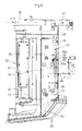
Fig. 16 is a longitudinal cross section of a portion of a rear cover of a swivel stage according to another embodiment. - Hereinbelow, embodiments of the present invention will be described with reference to the accompanying drawings.
- As shown in
Figs. 1 to 4 , abackhoe 1 as one example of a swiveling work machine includes a traveling device with a pair of right and left crawler track traveling bodies (not shown), and aswivel stage 2. Theswivel stage 2 is mounted above the traveling device through a swivel bearing, rotatably about a swivel shaft center extending in a vertical direction. - The
swivel stage 2 includes aswivel base 3 in a shape of a plate and avertical wall 5 partitioning a space above theswivel base 3 into front and rear spaces. Thevertical wall 5 stands on theswivel base 3 in an intermediate portion thereof in a longitudinal direction. Theswivel base 3 is provided with a pair of right and leftlongitudinal ribs swivel base 3. On a front side of a pair of the right and leftlongitudinal ribs bracket 9 is provided so as to protrude frontward from theswivel base 3. Through thebracket 9, a working device for excavation is installed on a front end portion of theswivel stage 2. - A rear end portion of the
swivel base 3 is provided with acounter weight 11. Frontward of thecounter weight 11 in the rear end portion of theswivel base 3, amounting wall 12 in a shape of an arc protrudes upward. Frontward of themounting wall 12 in the rear end portion of theswivel base 3, anengine 14 is disposed. On a left portion of theswivel base 3, a fuel tank is disposed, and on a right portion of theswivel base 3, a battery and an oil tank are disposed. The fuel tank is arranged frontward of thevertical wall 5 and on an immediate left side of the leftlongitudinal rib 6. The battery and oil tank are arranged frontward of thevertical wall 5 and on a right side of the rightlongitudinal rib 7. - In this manner, on a rear side of the
vertical wall 5 of theswivel stage 2 is formed anengine room 20. Theengine 14, aradiator 15 and the like are mounted on a rear portion of theswivel stage 2, and ahydraulic pump 16 is disposed on a left side of theengine 14. - As shown in
Fig. 5 , frontward of theengine 14 on theswivel stage 2, afront cover 22 is provided which is configured to serve as a partition on a front side of theengine room 20. A lower end portion of thefront cover 22 is fixed to thevertical wall 5 with fixtures, such as bolt. Arear cover 24 is provided on a rear end portion of theswivel stage 2, aleft cover 25 is provided on a left side of therear cover 24 on theswivel stage 2, a rightinner wall cover 26 is provided on a right side of thefront cover 22 on theswivel stage 2, and aright cover 28 is provided on a right side of the rightinner wall cover 26 on theswivel stage 2. - The
front cover 22 includes: a standingwall 31 as a lower front end portion of thefront cover 22; aninclined wall 32 extending rearward and upward from an upper end of the standingwall 31; and anupper wall 33 extending rearward from an upper end of theinclined wall 32. A lower portion of the standingwall 31 overlaps an upper end portion of thevertical wall 5, and fixed to thevertical wall 5 with fixtures, such as bolt and nut. On theinclined wall 32 of thefront cover 22, anopening window 35 for inspection purpose is provided, which is closed with a detachable lid member (not shown). - The
rear cover 24 is disposed above thecounter weight 11. Thecounter weight 11 and therear cover 24 together cover a rear side of theengine room 20. Theleft cover 25 covers a left side of theengine room 20. Thevertical wall 5 and thefront cover 22 together cover the front side and an upper side of theengine room 20. A rear portion of theright cover 28 covers a right side of theengine room 20. In this manner, thevertical wall 5, thefront cover 22, theleft cover 25, a rear portion of theright cover 28, thecounter weight 11 and therear cover 24 together surround the engine 14 (the engine room 20). Theright cover 28 covers a right side of the devices on theswivel stage 2, such as battery and oil tank, and the right side of theengine room 20. Theright cover 28 also covers front, upper and outer side portions of a right front area of theswivel base 3 where the devices, such as battery and oil tank, are mounted. The rightinner wall cover 26 covers an inner side portion of the right front area of theswivel base 3 where the devices, such as battery and oil tank, are mounted. - A
rear bonnet 36 is formed of thefront cover 22, theleft cover 25, the rear portion of theright cover 28 and therear cover 24, and aside bonnet 37 is formed of theright cover 28 and the rightinner wall cover 26. - As shown in
Figs. 1 and2 , on a front side of thevertical wall 5 of theswivel stage 2 and thefront cover 22, an operation part is provided that has a driver'sseat 38 and steering levers. On thefront cover 22, acanopy 39 for protecting the driver's seat 38 (operation part) stands. - As shown in
Figs. 2 to 8 , asupport frame 43 is provided on the rear portion of theswivel stage 2. Thesupport frame 43 straddles theengine 14 thereabove. Thesupport frame 43 is formed mainly of a left-front leg 45, a left-rear leg 46, a right-rear leg 47, a right-front leg 48 (not shown), alateral support plate 49 and alongitudinal support plate 50. Thelateral support plate 49 is connected to upper end portions of thelegs longitudinal support plate 50 protrudes frontward from a right end portion of thelateral support plate 49, and the right-front leg 48 supports a front portion of thelongitudinal support plate 50. - Lower ends of the left-
front leg 45 and the right-front leg 48 are fixed to theswivel base 3 through thevertical wall 5 and the like. Lower ends of the left-rear leg 46 and the right-rear leg 47 are fixed to theswivel base 3 through mountingstages lateral support plate 49 is in a shape of a band extending in a transversal direction. A left end portion of thelateral support plate 49 and the upper end portion of the left-front leg 45 are connected and fixed to each other by welding or the like. An intermediate portion of thelateral support plate 49 in the transversal direction is connected and fixed to the upper end portion of the left-rear leg 46 by welding or the like. The right end portion of thelateral support plate 49 is connected and fixed to the upper end portion of the right-rear leg 47 by welding or the like. A rear end portion of thelongitudinal support plate 50 is connected and fixed to the right end portion of thelateral support plate 49 and also to the upper end portion of the right-rear leg 47 by welding or the like. - As shown in
Figs. 5 to 8 , theleft cover 25 is supported by and fixed to thelateral support plate 49 of thesupport frame 43 through a mountingbracket 53 or the like. The rightinner wall cover 26 is supported and fixed to thelateral support plate 49 through a mounting bracket or the like. Theright cover 28 is supported by thelongitudinal support plate 50 of thesupport frame 43 through a hinge, in such a manner that theright cover 28 is freely opened and closed about a shaft extending in the longitudinal direction. Theupper wall 33 of thefront cover 22 is positioned right above thelateral support plate 49, and fixed to thelateral support plate 49 with fixtures, such as bolt and nut. - As shown in
Figs. 6 to 8 ,13 and16 , a plurality of fixingpieces 59 protrude rearward from thelateral support plate 49, and are arranged at predetermined intervals in the transversal direction. Each of these fixingpieces 59 includes a mountingbase 59a which is a horizontal front side portion, and aninclined fixing portion 59b which is a rear side portion sloping upward toward the rear. A rear portion of theupper wall 33 of thefront cover 22 is positioned above the fixingpieces 59, and a rear end portion of theupper wall 33 is fixed to the inclined fixingportions 59b withfixtures 60, such as bolt. It should be noted that the rear end portion of theupper wall 33 is formed as aninclined part 33a sloping upward toward the rear so as to correspond to the slope of the inclined fixingportion 59b. - As shown in
Figs. 5 and13 , apartition cover 62 is fixed to the right-rear leg 47 of thesupport frame 43, so as to extend along a right end (free end in the transversal direction) of therear cover 24. Thepartition cover 62 is configured to separate a space around theradiator 15 into an upstream-side space and a downstream-side space in terms of an air flow direction. Thepartition cover 62 separates a space on a rear side of theradiator 15 into a right space and a left space, by extending along a rear portion of a periphery of theradiator 15. With respect to separation of other spaces around theradiator 15, i.e., spaces on a front side, on a right side and on a left side, other partition covers or the like (not shown) are used. - As shown in
Figs. 5 ,7 ,8 ,11 and12 , therear cover 24 includes: a covermain body 64; and anupper cover body 65 fixed to an upper end portion of the covermain body 64 in such a manner that theupper cover body 65 protrudes frontward. The covermain body 64 includes: arear wall 64a; and a mountingrim 64b frontward protruding from an upper end of therear wall 64a. Therear wall 64a, when seen from above, is curved in a shape of an arc with an intermediate portion in the transversal direction swelling rearward and a right and left end portions jutting frontward. At the same time, an upper portion of therear wall 64a is curved frontward. Theupper cover body 65 includes: anupper wall 65a; a pair of right and leftside walls 65b extending downward from corresponding lateral ends of theupper wall 65a; and arear wall 65c extending downward from a rear end of theupper wall 65a. A rear portion (rear wall 65c) of theupper cover body 65 is mounted on the mountingrim 64b of the covermain body 64 and fastened with fastenings, such as bolt, in such a manner that theupper cover body 65 is detachable from the covermain body 64. - As shown in
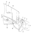
Figs. 7 to 10 and12 , on an inner face of a left end portion of the cover main body 64 (the rear cover 24), a mountingmember 68 in a square U-shape is provided, with an opening thereof facing the covermain body 64. To the mountingmember 68, a supportingmember 69 is fixed with fixtures, such as bolt. To a protruding end of the supportingmember 69, a pair of upper andlower support cylinders 70 are attached. On a left end portion of thelateral support plate 49, a squaredU-shaped support bracket 72 is provided while protruding rearward from thelateral support plate 49, to which anupper support 73 is fixed with fixtures, such as bolt. Theupper support 73 is connected to a connectingbody 75 through alower support 74. Between theupper support 73 and thelower support 74, avertical shaft 77 is provided. Thevertical shaft 77 is inserted into the pair of upper andlower support cylinders 70 relatively rotatably about a shaft center thereof. With this configuration, therear cover 24 is supported by thesupport frame 43 in such a manner that therear cover 24 is freely opened and closed about thevertical shaft 77 as a fulcrum shaft on a left end of the rear cover 24 (hereinafter, frequently referred to as "open-close cover 24"). - On an inner face of a right end portion of the
rear cover 24, alock mechanism 79 is provided. Thelock mechanism 79 is configured to be automatically engaged with an engaging portion provided on thesupport frame 43 when therear cover 24 is closed, in such a manner that therear cover 24 is releasably held in a locked state. - As shown in
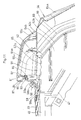
Figs. 11 and12 , from theupper wall 65a of the upper cover body 65 (the rear cover 24), acover piece 81 protrudes frontward. On thecover piece 81, a suspendedpiece 82 is provided that protrudes downward from a base portion of thecover piece 81. On theupper wall 33 of the front cover 22 (an upper end of theinclined part 33a of the upper wall 33), a standingpiece 83 is provided that stands opposite to the suspendedpiece 82, when therear cover 24 is closed. The standingpiece 83 is positioned below thecover piece 81, when therear cover 24 is closed. On the suspendedpiece 82, a sealingmember 84 is attached so as to be brought into contact with the standingpiece 83, when the open-close cover 24 is closed. The sealingmember 84 spans a nearly entire length of therear cover 24 in the transversal direction. In addition, the sealingmember 84 includes a fixingportion 85 having a U-shaped cross-section and a cylindrical contactingportion 86, with the fixingportion 85 being fitted onto and fixed to a lower portion of the suspendedpiece 82 from a bottom side. The sealingmember 84 is configured to make a seal between an upper end portion of therear cover 24 and an upper end portion of thefront cover 22 along a nearly entire length in the transversal direction, by pressing and bringing the contactingportion 86 of the sealingmember 84 into a close contact with the standingpiece 83, when therear cover 24 is closed. - On a protruding end portion (front end portion) of the
cover piece 81, there is provided adownward protrusion 87 in such a manner that the standingpiece 83 is positioned below thecover piece 81 and on a suspendedpiece 82 side (rear side) relative to thedownward protrusion 87, when therear cover 24 is closed. - The
cover piece 81 protrudes frontward further in the longitudinal direction than a front end of the sealingmember 84, or protrudes frontward to approximately the same level in the longitudinal direction as the front end of the sealingmember 84. When therear cover 24 is closed and the sealingmember 84 is elastically deformed rearward relative to thecover piece 81 by being pressed to the upper end portion (the standing piece 83) of thefront cover 22, thecover piece 81 is located above the sealingmember 84 and reaches a position above theupper wall 33 of the front cover 22 (the standingpiece 83 or the rear end portion of the upper wall 33). - On a free end portion of the upper cover body 65 (a lower end portion of a
right side wall 65b), there is provided anupper sealing member 90 which is brought into contact with atop wall 62a of thepartition cover 62 when therear cover 24 is closed, while on a free end portion of the cover main body 64 (the right end portion of therear wall 64a), there is provided arear sealing member 88 which is brought into contact with arear wall 62b of thepartition cover 62 through aprotrusion 89 when therear cover 24 is closed. On a base end portion of the cover main body 64 (left end portion of therear wall 64a), a baseend sealing member 91 is provided through aprotrusion 92, which is configured to be brought into contact with a right end portion of theleft cover 25 when therear cover 24 is closed, to thereby make a seal between theleft cover 25 and therear cover 24. - As shown in
Figs. 1 ,14 and15 , on a left upper portion of thecounter weight 11, an openingwindow 95 is provided at a position corresponding to a position of thehydraulic pump 16, and acover member 96 for closing theopening window 95 is detachably provided on thecounter weight 11 with afastening 97, such as bolt. Accordingly, when thehydraulic pump 16 is to be removed from theswivel stage 2 for the purpose of inspection or the like, it is not necessary to remove theentire counter weight 11, and simply removing thecover member 96 will suffice. It should be noted that thecover member 96 is made of synthetic resin or the like. - According to the above-described embodiment, when the
rear cover 24 is rotated about thevertical shaft 77 to close therear cover 24, the sealingmember 84 on theupper cover body 65 is pressed and brought into a close contact with the standingpiece 83 on thefront cover 22, to thereby make a seal between the upper end portion of therear cover 24 and the upper end portion of thefront cover 22 along a nearly entire length in the transversal direction. In this situation, the standingpiece 83 is positioned below thecover piece 81 and on the suspendedpiece 82 side (rear side) relative to thedownward protrusion 87, and thecover piece 81 is located above the sealingmember 84 and reaches a position above theupper wall 33 of the front cover 22 (a standingpiece 83 or rear end portion of the upper wall 33). Therefore, even when it snows on therear bonnet 36, or even when soil lifted during excavation work or the like drops on therear bonnet 36, thecover piece 81 and thedownward protrusion 87 can protect an upper side of the sealingmember 84, and thus prevent snow and soil from accumulated on the sealingmember 84. Accordingly, snow or soil is prevented from being accumulated on the sealingmember 84 or portions of the cover in the vicinity thereof, and thus the sealingmember 84 and portions of the cover in the vicinity thereof are prevented in advance from becoming fixed in an attached state which may otherwise be caused by frozen snow or soil. - In addition, when the
rear cover 24 is closed, the upper sealingmember 90 on the free end portion of the upper cover body 65 (a lower end portion of aright side wall 65b) is brought into contact with thetop wall 62a of thepartition cover 62, and at the same time, therear sealing member 88 on the free end portion (a right end portion of a rear wall) of the covermain body 64 is brought into contact with therear wall 62b of thepartition cover 62, to thereby make a seal between therear cover 24 and thepartition cover 62. The baseend sealing member 91 on the base end portion of the cover main body 64 (left end portion of therear wall 64a) is brought into contact with the right end portion of theleft cover 25, to thereby make a seal between theleft cover 25 and therear cover 24. -
Fig. 16 shows another embodiment in which the sealingmember 84 is provided on an upper end portion of the standingpiece 83 of thefront cover 22. When therear cover 24 is rotated about thevertical shaft 77 to close therear cover 24, the sealingmember 84 on the standingpiece 83 is pressed and brought into a close contact with the suspendedpiece 82 on therear cover 24, to thereby make a seal between the upper end portion of therear cover 24 and the upper end portion of thefront cover 22 along a nearly entire length in the transversal direction. In this situation, the standingpiece 83 is positioned below thecover piece 81 and on the suspendedpiece 82 side (rear side) relative to atip portion 81A of thecover piece 81, and thecover piece 81 is located above the sealingmember 84 and reaches a position above theupper wall 33 of the front cover 22 (the standingpiece 83 or the rear end portion of the upper wall 33). Other features are substantially the same as those described in the above-mentioned embodiment, and thus the descriptions are omitted. - It should be noted that, in the above-described embodiments illustrated in
Figs. 11 and16 , thecover piece 81 protrudes from theupper wall 65a of the open-close cover 24, so as to be located above the sealingmember 84 and reach a position above theupper wall 33 of a fixedcover 22, when the open-close cover 24 is closed. Accordingly, when therear bonnet 36 is seen from behind, a step between the open-close cover 24 and the fixedcover 22 is covered with thecover piece 81 and the like, which makes a shape of therear bonnet 36 simpler and contributes to an excellent appearance. Instead, thecover piece 81 may protrude from theupper wall 33 of the fixedcover 22, so as to be located above the sealingmember 84 and reach a position above theupper wall 65a of the open-close cover 24, when the open-close cover 24 is closed. - Also in the above-described embodiments illustrated in
Figs. 11 and16 , thecover piece 81 is provided on theupper wall 65a of the open-close cover 24, the suspendedpiece 82 downward protrudes from the base portion of thecover piece 81, and the standingpiece 83 is provided on a rear end portion of theupper wall 33 of the fixedcover 22, that stands opposite to the suspendedpiece 82. Instead, thecover piece 81 may be provided on theupper wall 33 of the fixedcover 22, the suspendedpiece 82 may downward protrude from the base portion of thecover piece 81, and the standingpiece 83 is provided on a front end portion of theupper wall 65a of the open-close cover 24, that stands opposite to the suspendedpiece 82. In addition, in this case, the sealingmember 84 may be attached to the suspendedpiece 82, or alternatively, to the standingpiece 83. - Moreover, in the embodiments described above, the
rear cover 24 to be opened and closed is supported openably and closably about thevertical shaft 77 as a fulcrum shaft on the left end portion in the transversal direction of therear cover 24. Instead, therear cover 24 to be opened and closed may be supported openably and closably about thevertical shaft 77 as a fulcrum shaft on the right end portion in the transversal direction. - Also in the embodiments described above, the
front cover 22 is a fixed cover and therear cover 24 is an open-close cover, and when therear cover 24 is closed, the upper end portion of therear cover 24 is brought into contact with the upper end portion of thefront cover 22 through the sealingmember 84. However, the fixed cover is not limited to thefront cover 22, and the open-close cover is not limited to therear cover 24. For example, theleft cover 25 may be a cover to be opened and closed, and thefront cover 22 may be a cover to be fixed. In this case, theleft cover 25 is made openable and closable about thevertical shaft 77, to thereby bring an upper end portion of theleft cover 25 into contact with the upper end portion of thefront cover 22 through the sealingmember 84, when theleft cover 25 is closed.
Claims (5)
- A bonnet sealing structure for a swiveling work machine comprising:a bonnet (36) configured to cover an engine (14) provided on a swivel stage (2) including:a fixed cover (22), andan open-close cover (24) which is swingably supported about a vertical shaft (77) and is openable and closable relative to the fixed cover (22); anda sealing member (84) through which an upper end portion of the open-close cover (24) is brought into contact with an upper end portion of the fixed cover (22) when the open-close cover (24) is closed, characterized in thatthe bonnet sealing structure further comprises a cover piece (81) protruding from one of an upper wall (65a) of the open-close cover (24) and an upper wall (33) of the fixed cover (22), and when the open-close cover (24) is closed, the cover piece (81) is located above the sealing member (84) and reaches a point above the other of the upper wall (33) of the fixed cover (22) and the upper wall (65a) of the open-close cover (21).
- The bonnet sealing structure according to Claim 1, characterized in thatthe cover piece (81) is provided on the upper wall (65a) of the open-close cover (24), and is provided with a suspended piece (82) protruding downward from a base portion of the cover piece (81),a standing piece (83) is provided on an end portion of the upper wall (33) of the fixed cover (22), that stands opposite to the suspended piece (82) and is positioned below the cover piece (81) when the open-close cover (24) is closed, andthe sealing member (84) is provided on one of the suspended piece (82) and the standing piece (83), and is brought into contact with the other of the suspended piece (82) and the standing piece (83) when the open-close cover (24) is closed.
- The bonnet sealing structure according to Claim 2, characterized in thatthe engine (14) and a radiator (15) are mounted on a rear portion of the swivel stage (2),a support frame (43) straddles the engine (14),the fixed cover (22) configured to cover upper and front sides of the engine (14) is fixed to the support frame (43),the open-close cover (24) configured to cover a rear side of the engine (14) is supported by the support frame (43) in such a manner that the open-close cover (24) is freely opened and closed about the vertical shaft (77) as a fulcrum shaft on one end in a transversal direction of the open-close cover (24),the open-close cover (24) comprisesa cover main body (64); andan upper cover body (65) which is fixed to an upper end portion ofthe cover main body (64) and protrudes frontward, andthe upper cover body (65) includes the upper wall (65a) on which the cover piece (81) and the suspended piece (82) are provided.
- The bonnet sealing structure according to Claim 3, characterized in thata partition cover (62) configured to separate a space around the radiator (15) into an upstream-side space and a downstream-side space in terms of an air flow direction is fixed to the support frame (43) so as to extend along a free end portion in the transversal direction of the open-close cover (24),the partition cover (62) comprises:a top wall (62a); anda rear wall (62b) protruding downward from a rear end of the top wall (62a),on a free end portion of the upper cover body (65), an upper sealing member (90) is provided which is brought into contact with the top wall (62a) of the partition cover (62) when the open-close cover (24) is closed, andon a free end portion of the cover main body (64), a rear sealing member (88) is provided which is brought into contact with the rear wall (62b) of the partition cover (62) when the open-close cover (24) is closed.
- The bonnet sealing structure according to Claim 4, characterized in thata downward protrusion (87) protrudes downward from a protruding end portion of the cover piece (81), andthe standing piece (83) is positioned below the cover piece (81) and on a suspended piece (82) side relative to the downward protrusion (87), when the open-close cover (24) is closed.
Applications Claiming Priority (1)
| Application Number | Priority Date | Filing Date | Title |
|---|---|---|---|
| JP2008293491A JP5061085B2 (en) | 2008-11-17 | 2008-11-17 | Bonnet seal structure of swivel work machine |
Publications (3)
| Publication Number | Publication Date |
|---|---|
| EP2186949A2 true EP2186949A2 (en) | 2010-05-19 |
| EP2186949A3 EP2186949A3 (en) | 2014-01-22 |
| EP2186949B1 EP2186949B1 (en) | 2015-12-02 |
Family
ID=41600451
Family Applications (1)
| Application Number | Title | Priority Date | Filing Date |
|---|---|---|---|
| EP09170884.2A Active EP2186949B1 (en) | 2008-11-17 | 2009-09-21 | Bonnet for a swivelling work machine |
Country Status (5)
| Country | Link |
|---|---|
| US (1) | US8528681B2 (en) |
| EP (1) | EP2186949B1 (en) |
| JP (1) | JP5061085B2 (en) |
| KR (1) | KR101143135B1 (en) |
| CN (1) | CN101736770B (en) |
Cited By (1)
| Publication number | Priority date | Publication date | Assignee | Title |
|---|---|---|---|---|
| EP4406780A3 (en) * | 2019-06-26 | 2025-01-08 | Kubota Corporation | Work machine |
Families Citing this family (10)
| Publication number | Priority date | Publication date | Assignee | Title |
|---|---|---|---|---|
| JP4686565B2 (en) * | 2008-03-31 | 2011-05-25 | 株式会社クボタ | Superstructure of work equipment |
| JP5061085B2 (en) * | 2008-11-17 | 2012-10-31 | 株式会社クボタ | Bonnet seal structure of swivel work machine |
| JP5411173B2 (en) * | 2011-02-07 | 2014-02-12 | 日立建機株式会社 | Construction machine swivel frame |
| JP5758338B2 (en) * | 2012-03-29 | 2015-08-05 | 株式会社クボタ | Working machine |
| JP5923391B2 (en) * | 2012-06-11 | 2016-05-24 | 株式会社クボタ | Working machine |
| JP6028588B2 (en) * | 2013-01-22 | 2016-11-16 | コベルコ建機株式会社 | Work machine |
| CN104444973B (en) * | 2014-11-12 | 2016-11-16 | 湖南星邦重工有限公司 | Job platform and the cladding system of turntable thereof |
| WO2017056556A1 (en) * | 2015-09-30 | 2017-04-06 | 株式会社クボタ | Work machine |
| JP7126993B2 (en) * | 2019-06-26 | 2022-08-29 | 株式会社クボタ | work machine |
| JP7191783B2 (en) * | 2019-06-26 | 2022-12-19 | 株式会社クボタ | work machine |
Citations (2)
| Publication number | Priority date | Publication date | Assignee | Title |
|---|---|---|---|---|
| JP2004150029A (en) | 2002-10-28 | 2004-05-27 | Shin Caterpillar Mitsubishi Ltd | Working machine |
| JP2005280485A (en) | 2004-03-29 | 2005-10-13 | Kubota Corp | Cover device for swivel work machine |
Family Cites Families (27)
| Publication number | Priority date | Publication date | Assignee | Title |
|---|---|---|---|---|
| JPH0211254Y2 (en) * | 1984-11-14 | 1990-03-20 | ||
| JPH0880740A (en) * | 1994-09-14 | 1996-03-26 | Suzuki Motor Corp | Weather strip structure |
| DE69603210T2 (en) * | 1995-02-17 | 2000-01-20 | Kubota Corp., Osaka | Bucket excavator with a hood to which the driver's seat is attached |
| JP3572719B2 (en) * | 1995-05-16 | 2004-10-06 | コベルコ建機株式会社 | Hydraulic working machine |
| KR0170941B1 (en) * | 1995-10-30 | 1999-03-20 | 배순훈 | Method for forming a photoresist pattern |
| KR970041610A (en) * | 1995-12-27 | 1997-07-24 | 한승준 | Bonnet Seal Structure |
| KR970039030A (en) * | 1995-12-28 | 1997-07-24 | 한승준 | Bonnet shear seal structure |
| JPH09189050A (en) * | 1996-01-11 | 1997-07-22 | Hitachi Constr Mach Co Ltd | External cover mounting structure for construction machinery |
| KR19980065019U (en) * | 1997-04-30 | 1998-11-25 | 토니 헬샴 | Heavy-duty counterweight structure |
| JP3533077B2 (en) * | 1997-12-26 | 2004-05-31 | コベルコ建機株式会社 | Guard cover for construction machinery |
| US6565148B1 (en) * | 1999-09-10 | 2003-05-20 | Toyoda Gosei Co., Ltd. | Assembly structure for cowl louver |
| JP4236229B2 (en) * | 1999-10-08 | 2009-03-11 | 株式会社小松製作所 | Sound absorbing blade mounting structure for work vehicle |
| US6626256B2 (en) * | 1999-12-09 | 2003-09-30 | International Truck Intellectual Property Company, Llc | Access hatch reinforcement module & method of installing an access hatch to an existing hood for a mobile vehicle |
| US6634449B2 (en) * | 1999-12-09 | 2003-10-21 | International Truck Intellectual Property Company, Llc | Access hatch reinforcement module & method of installing an access hatch to an existing hood for a mobile vehicle |
| JP3626392B2 (en) * | 2000-04-24 | 2005-03-09 | 株式会社クボタ | Backhoe swivel |
| JP4211919B2 (en) * | 2003-03-24 | 2009-01-21 | 株式会社小松製作所 | Hydraulic excavator counterweight |
| JP4226546B2 (en) * | 2004-03-29 | 2009-02-18 | 株式会社クボタ | Swivel work machine |
| JP4266868B2 (en) * | 2004-03-29 | 2009-05-20 | 株式会社クボタ | Swivel platform structure of swivel work machine |
| CN100482901C (en) | 2004-03-29 | 2009-04-29 | 株式会社久保田 | Swiveling utility machine having swivel deck |
| US7255189B2 (en) * | 2004-06-18 | 2007-08-14 | Cnh America Llc | Radiator mounting system |
| JP4515232B2 (en) * | 2004-11-22 | 2010-07-28 | 株式会社クボタ | Swivel work machine |
| JP4619168B2 (en) * | 2005-03-28 | 2011-01-26 | 株式会社クボタ | Swivel work machine |
| US7828097B2 (en) * | 2005-07-05 | 2010-11-09 | Yanmar Co., Ltd. | Construction machine |
| CN101542045B (en) * | 2006-11-28 | 2011-12-07 | 日立建机株式会社 | Construction machine |
| JP4686565B2 (en) * | 2008-03-31 | 2011-05-25 | 株式会社クボタ | Superstructure of work equipment |
| JP5185721B2 (en) * | 2008-07-29 | 2013-04-17 | 日立建機株式会社 | Construction machinery |
| JP5061085B2 (en) * | 2008-11-17 | 2012-10-31 | 株式会社クボタ | Bonnet seal structure of swivel work machine |
-
2008
- 2008-11-17 JP JP2008293491A patent/JP5061085B2/en active Active
-
2009
- 2009-08-31 KR KR1020090080862A patent/KR101143135B1/en not_active Expired - Fee Related
- 2009-09-17 US US12/561,709 patent/US8528681B2/en active Active
- 2009-09-21 EP EP09170884.2A patent/EP2186949B1/en active Active
- 2009-09-23 CN CN2009101780160A patent/CN101736770B/en active Active
Patent Citations (2)
| Publication number | Priority date | Publication date | Assignee | Title |
|---|---|---|---|---|
| JP2004150029A (en) | 2002-10-28 | 2004-05-27 | Shin Caterpillar Mitsubishi Ltd | Working machine |
| JP2005280485A (en) | 2004-03-29 | 2005-10-13 | Kubota Corp | Cover device for swivel work machine |
Cited By (1)
| Publication number | Priority date | Publication date | Assignee | Title |
|---|---|---|---|---|
| EP4406780A3 (en) * | 2019-06-26 | 2025-01-08 | Kubota Corporation | Work machine |
Also Published As
| Publication number | Publication date |
|---|---|
| KR20100055318A (en) | 2010-05-26 |
| KR101143135B1 (en) | 2012-05-11 |
| US20100122862A1 (en) | 2010-05-20 |
| CN101736770A (en) | 2010-06-16 |
| EP2186949A3 (en) | 2014-01-22 |
| EP2186949B1 (en) | 2015-12-02 |
| US8528681B2 (en) | 2013-09-10 |
| CN101736770B (en) | 2013-02-13 |
| JP5061085B2 (en) | 2012-10-31 |
| JP2010121290A (en) | 2010-06-03 |
Similar Documents
| Publication | Publication Date | Title |
|---|---|---|
| EP2186949B1 (en) | Bonnet for a swivelling work machine | |
| US11313101B2 (en) | Construction machine | |
| US9327772B2 (en) | Cabin device of working machine | |
| US7975793B1 (en) | Tilting foot pod for the operator cab of a skid steer vehicle | |
| US20040079414A1 (en) | Valve and tank enclosure assembly | |
| JP2009243069A (en) | Backhoe | |
| JPH10252592A (en) | Fuel pump unit support structure | |
| KR101669836B1 (en) | Waterproof structure for outer roof | |
| US20090084003A1 (en) | Excavating Machine | |
| JP4915157B2 (en) | Construction machinery | |
| US9694667B2 (en) | Working vehicle | |
| JP4606293B2 (en) | Backhoe | |
| JP6414136B2 (en) | Construction machinery | |
| JP4468872B2 (en) | Construction machinery | |
| JP3792024B2 (en) | Scooter type vehicle seat arrangement structure | |
| KR102872866B1 (en) | work machine | |
| JPH09273176A (en) | Backhoe | |
| JP2006021638A (en) | Motorcycle | |
| JP6940550B2 (en) | Car hood support structure | |
| JP2005047334A (en) | Saddle-type vehicle fuel tank | |
| JP4101849B2 (en) | Swivel work machine | |
| JP3632438B2 (en) | Car air box structure | |
| JP3947075B2 (en) | Swivel work machine | |
| KR101239423B1 (en) | Main frame assembly of excavator | |
| JP4738188B2 (en) | Work vehicle canopy |
Legal Events
| Date | Code | Title | Description |
|---|---|---|---|
| PUAI | Public reference made under article 153(3) epc to a published international application that has entered the european phase |
Free format text: ORIGINAL CODE: 0009012 |
|
| 17P | Request for examination filed |
Effective date: 20091020 |
|
| AK | Designated contracting states |
Kind code of ref document: A2 Designated state(s): AT BE BG CH CY CZ DE DK EE ES FI FR GB GR HR HU IE IS IT LI LT LU LV MC MK MT NL NO PL PT RO SE SI SK SM TR |
|
| AX | Request for extension of the european patent |
Extension state: AL BA RS |
|
| PUAL | Search report despatched |
Free format text: ORIGINAL CODE: 0009013 |
|
| AK | Designated contracting states |
Kind code of ref document: A3 Designated state(s): AT BE BG CH CY CZ DE DK EE ES FI FR GB GR HR HU IE IS IT LI LT LU LV MC MK MT NL NO PL PT RO SE SI SK SM TR |
|
| AX | Request for extension of the european patent |
Extension state: AL BA RS |
|
| RIC1 | Information provided on ipc code assigned before grant |
Ipc: E02F 3/32 20060101ALI20131217BHEP Ipc: E02F 9/08 20060101AFI20131217BHEP |
|
| RBV | Designated contracting states (corrected) |
Designated state(s): AT BE BG CH CY CZ DE DK EE ES FI FR GB GR HR HU IE IS IT LI LT LU LV MC MK MT NL NO PL PT RO SE SI SK SM TR |
|
| 17Q | First examination report despatched |
Effective date: 20140904 |
|
| GRAP | Despatch of communication of intention to grant a patent |
Free format text: ORIGINAL CODE: EPIDOSNIGR1 |
|
| INTG | Intention to grant announced |
Effective date: 20150617 |
|
| GRAS | Grant fee paid |
Free format text: ORIGINAL CODE: EPIDOSNIGR3 |
|
| GRAA | (expected) grant |
Free format text: ORIGINAL CODE: 0009210 |
|
| AK | Designated contracting states |
Kind code of ref document: B1 Designated state(s): AT BE BG CH CY CZ DE DK EE ES FI FR GB GR HR HU IE IS IT LI LT LU LV MC MK MT NL NO PL PT RO SE SI SK SM TR |
|
| REG | Reference to a national code |
Ref country code: GB Ref legal event code: FG4D |
|
| REG | Reference to a national code |
Ref country code: AT Ref legal event code: REF Ref document number: 763699 Country of ref document: AT Kind code of ref document: T Effective date: 20151215 Ref country code: CH Ref legal event code: EP |
|
| REG | Reference to a national code |
Ref country code: IE Ref legal event code: FG4D |
|
| REG | Reference to a national code |
Ref country code: DE Ref legal event code: R096 Ref document number: 602009035069 Country of ref document: DE |
|
| REG | Reference to a national code |
Ref country code: DE Ref legal event code: R082 Ref document number: 602009035069 Country of ref document: DE Representative=s name: KUHNEN & WACKER PATENT- UND RECHTSANWALTSBUERO, DE |
|
| REG | Reference to a national code |
Ref country code: NL Ref legal event code: MP Effective date: 20160302 |
|
| REG | Reference to a national code |
Ref country code: LT Ref legal event code: MG4D |
|
| REG | Reference to a national code |
Ref country code: AT Ref legal event code: MK05 Ref document number: 763699 Country of ref document: AT Kind code of ref document: T Effective date: 20151202 |
|
| PG25 | Lapsed in a contracting state [announced via postgrant information from national office to epo] |
Ref country code: HR Free format text: LAPSE BECAUSE OF FAILURE TO SUBMIT A TRANSLATION OF THE DESCRIPTION OR TO PAY THE FEE WITHIN THE PRESCRIBED TIME-LIMIT Effective date: 20151202 Ref country code: ES Free format text: LAPSE BECAUSE OF FAILURE TO SUBMIT A TRANSLATION OF THE DESCRIPTION OR TO PAY THE FEE WITHIN THE PRESCRIBED TIME-LIMIT Effective date: 20151202 Ref country code: LT Free format text: LAPSE BECAUSE OF FAILURE TO SUBMIT A TRANSLATION OF THE DESCRIPTION OR TO PAY THE FEE WITHIN THE PRESCRIBED TIME-LIMIT Effective date: 20151202 Ref country code: NO Free format text: LAPSE BECAUSE OF FAILURE TO SUBMIT A TRANSLATION OF THE DESCRIPTION OR TO PAY THE FEE WITHIN THE PRESCRIBED TIME-LIMIT Effective date: 20160302 |
|
| PG25 | Lapsed in a contracting state [announced via postgrant information from national office to epo] |
Ref country code: LV Free format text: LAPSE BECAUSE OF FAILURE TO SUBMIT A TRANSLATION OF THE DESCRIPTION OR TO PAY THE FEE WITHIN THE PRESCRIBED TIME-LIMIT Effective date: 20151202 Ref country code: GR Free format text: LAPSE BECAUSE OF FAILURE TO SUBMIT A TRANSLATION OF THE DESCRIPTION OR TO PAY THE FEE WITHIN THE PRESCRIBED TIME-LIMIT Effective date: 20160303 Ref country code: NL Free format text: LAPSE BECAUSE OF FAILURE TO SUBMIT A TRANSLATION OF THE DESCRIPTION OR TO PAY THE FEE WITHIN THE PRESCRIBED TIME-LIMIT Effective date: 20151202 Ref country code: SE Free format text: LAPSE BECAUSE OF FAILURE TO SUBMIT A TRANSLATION OF THE DESCRIPTION OR TO PAY THE FEE WITHIN THE PRESCRIBED TIME-LIMIT Effective date: 20151202 Ref country code: FI Free format text: LAPSE BECAUSE OF FAILURE TO SUBMIT A TRANSLATION OF THE DESCRIPTION OR TO PAY THE FEE WITHIN THE PRESCRIBED TIME-LIMIT Effective date: 20151202 Ref country code: PL Free format text: LAPSE BECAUSE OF FAILURE TO SUBMIT A TRANSLATION OF THE DESCRIPTION OR TO PAY THE FEE WITHIN THE PRESCRIBED TIME-LIMIT Effective date: 20151202 Ref country code: AT Free format text: LAPSE BECAUSE OF FAILURE TO SUBMIT A TRANSLATION OF THE DESCRIPTION OR TO PAY THE FEE WITHIN THE PRESCRIBED TIME-LIMIT Effective date: 20151202 |
|
| PG25 | Lapsed in a contracting state [announced via postgrant information from national office to epo] |
Ref country code: IS Free format text: LAPSE BECAUSE OF FAILURE TO SUBMIT A TRANSLATION OF THE DESCRIPTION OR TO PAY THE FEE WITHIN THE PRESCRIBED TIME-LIMIT Effective date: 20151202 |
|
| PG25 | Lapsed in a contracting state [announced via postgrant information from national office to epo] |
Ref country code: CZ Free format text: LAPSE BECAUSE OF FAILURE TO SUBMIT A TRANSLATION OF THE DESCRIPTION OR TO PAY THE FEE WITHIN THE PRESCRIBED TIME-LIMIT Effective date: 20151202 Ref country code: IT Free format text: LAPSE BECAUSE OF FAILURE TO SUBMIT A TRANSLATION OF THE DESCRIPTION OR TO PAY THE FEE WITHIN THE PRESCRIBED TIME-LIMIT Effective date: 20151202 |
|
| REG | Reference to a national code |
Ref country code: FR Ref legal event code: PLFP Year of fee payment: 8 |
|
| PG25 | Lapsed in a contracting state [announced via postgrant information from national office to epo] |
Ref country code: RO Free format text: LAPSE BECAUSE OF FAILURE TO SUBMIT A TRANSLATION OF THE DESCRIPTION OR TO PAY THE FEE WITHIN THE PRESCRIBED TIME-LIMIT Effective date: 20151202 Ref country code: SK Free format text: LAPSE BECAUSE OF FAILURE TO SUBMIT A TRANSLATION OF THE DESCRIPTION OR TO PAY THE FEE WITHIN THE PRESCRIBED TIME-LIMIT Effective date: 20151202 Ref country code: EE Free format text: LAPSE BECAUSE OF FAILURE TO SUBMIT A TRANSLATION OF THE DESCRIPTION OR TO PAY THE FEE WITHIN THE PRESCRIBED TIME-LIMIT Effective date: 20151202 Ref country code: IS Free format text: LAPSE BECAUSE OF FAILURE TO SUBMIT A TRANSLATION OF THE DESCRIPTION OR TO PAY THE FEE WITHIN THE PRESCRIBED TIME-LIMIT Effective date: 20160402 Ref country code: SM Free format text: LAPSE BECAUSE OF FAILURE TO SUBMIT A TRANSLATION OF THE DESCRIPTION OR TO PAY THE FEE WITHIN THE PRESCRIBED TIME-LIMIT Effective date: 20151202 Ref country code: PT Free format text: LAPSE BECAUSE OF FAILURE TO SUBMIT A TRANSLATION OF THE DESCRIPTION OR TO PAY THE FEE WITHIN THE PRESCRIBED TIME-LIMIT Effective date: 20160404 |
|
| REG | Reference to a national code |
Ref country code: DE Ref legal event code: R097 Ref document number: 602009035069 Country of ref document: DE |
|
| PLBE | No opposition filed within time limit |
Free format text: ORIGINAL CODE: 0009261 |
|
| STAA | Information on the status of an ep patent application or granted ep patent |
Free format text: STATUS: NO OPPOSITION FILED WITHIN TIME LIMIT |
|
| PG25 | Lapsed in a contracting state [announced via postgrant information from national office to epo] |
Ref country code: DK Free format text: LAPSE BECAUSE OF FAILURE TO SUBMIT A TRANSLATION OF THE DESCRIPTION OR TO PAY THE FEE WITHIN THE PRESCRIBED TIME-LIMIT Effective date: 20151202 |
|
| 26N | No opposition filed |
Effective date: 20160905 |
|
| PG25 | Lapsed in a contracting state [announced via postgrant information from national office to epo] |
Ref country code: SI Free format text: LAPSE BECAUSE OF FAILURE TO SUBMIT A TRANSLATION OF THE DESCRIPTION OR TO PAY THE FEE WITHIN THE PRESCRIBED TIME-LIMIT Effective date: 20151202 |
|
| PG25 | Lapsed in a contracting state [announced via postgrant information from national office to epo] |
Ref country code: BE Free format text: LAPSE BECAUSE OF FAILURE TO SUBMIT A TRANSLATION OF THE DESCRIPTION OR TO PAY THE FEE WITHIN THE PRESCRIBED TIME-LIMIT Effective date: 20151202 |
|
| PG25 | Lapsed in a contracting state [announced via postgrant information from national office to epo] |
Ref country code: MC Free format text: LAPSE BECAUSE OF FAILURE TO SUBMIT A TRANSLATION OF THE DESCRIPTION OR TO PAY THE FEE WITHIN THE PRESCRIBED TIME-LIMIT Effective date: 20151202 |
|
| REG | Reference to a national code |
Ref country code: CH Ref legal event code: PL |
|
| GBPC | Gb: european patent ceased through non-payment of renewal fee |
Effective date: 20160921 |
|
| REG | Reference to a national code |
Ref country code: IE Ref legal event code: MM4A |
|
| PG25 | Lapsed in a contracting state [announced via postgrant information from national office to epo] |
Ref country code: GB Free format text: LAPSE BECAUSE OF NON-PAYMENT OF DUE FEES Effective date: 20160921 Ref country code: CH Free format text: LAPSE BECAUSE OF NON-PAYMENT OF DUE FEES Effective date: 20160930 Ref country code: IE Free format text: LAPSE BECAUSE OF NON-PAYMENT OF DUE FEES Effective date: 20160921 Ref country code: LI Free format text: LAPSE BECAUSE OF NON-PAYMENT OF DUE FEES Effective date: 20160930 |
|
| REG | Reference to a national code |
Ref country code: FR Ref legal event code: PLFP Year of fee payment: 9 |
|
| PG25 | Lapsed in a contracting state [announced via postgrant information from national office to epo] |
Ref country code: LU Free format text: LAPSE BECAUSE OF NON-PAYMENT OF DUE FEES Effective date: 20160921 |
|
| PG25 | Lapsed in a contracting state [announced via postgrant information from national office to epo] |
Ref country code: HU Free format text: LAPSE BECAUSE OF FAILURE TO SUBMIT A TRANSLATION OF THE DESCRIPTION OR TO PAY THE FEE WITHIN THE PRESCRIBED TIME-LIMIT; INVALID AB INITIO Effective date: 20090921 Ref country code: CY Free format text: LAPSE BECAUSE OF FAILURE TO SUBMIT A TRANSLATION OF THE DESCRIPTION OR TO PAY THE FEE WITHIN THE PRESCRIBED TIME-LIMIT Effective date: 20151202 |
|
| PG25 | Lapsed in a contracting state [announced via postgrant information from national office to epo] |
Ref country code: MT Free format text: LAPSE BECAUSE OF NON-PAYMENT OF DUE FEES Effective date: 20160930 Ref country code: TR Free format text: LAPSE BECAUSE OF FAILURE TO SUBMIT A TRANSLATION OF THE DESCRIPTION OR TO PAY THE FEE WITHIN THE PRESCRIBED TIME-LIMIT Effective date: 20151202 Ref country code: MK Free format text: LAPSE BECAUSE OF FAILURE TO SUBMIT A TRANSLATION OF THE DESCRIPTION OR TO PAY THE FEE WITHIN THE PRESCRIBED TIME-LIMIT Effective date: 20151202 |
|
| PG25 | Lapsed in a contracting state [announced via postgrant information from national office to epo] |
Ref country code: BG Free format text: LAPSE BECAUSE OF FAILURE TO SUBMIT A TRANSLATION OF THE DESCRIPTION OR TO PAY THE FEE WITHIN THE PRESCRIBED TIME-LIMIT Effective date: 20151202 |
|
| REG | Reference to a national code |
Ref country code: FR Ref legal event code: PLFP Year of fee payment: 10 |
|
| PGFP | Annual fee paid to national office [announced via postgrant information from national office to epo] |
Ref country code: DE Payment date: 20240730 Year of fee payment: 16 |
|
| PGFP | Annual fee paid to national office [announced via postgrant information from national office to epo] |
Ref country code: FR Payment date: 20240808 Year of fee payment: 16 |