EP2186713A2 - Ballast device and agricultural vehicle with such device - Google Patents
Ballast device and agricultural vehicle with such device Download PDFInfo
- Publication number
- EP2186713A2 EP2186713A2 EP09175752A EP09175752A EP2186713A2 EP 2186713 A2 EP2186713 A2 EP 2186713A2 EP 09175752 A EP09175752 A EP 09175752A EP 09175752 A EP09175752 A EP 09175752A EP 2186713 A2 EP2186713 A2 EP 2186713A2
- Authority
- EP
- European Patent Office
- Prior art keywords
- vehicle
- ballastiergewicht
- length
- ballast
- pivot
- Prior art date
- Legal status (The legal status is an assumption and is not a legal conclusion. Google has not performed a legal analysis and makes no representation as to the accuracy of the status listed.)
- Granted
Links
- 230000005484 gravity Effects 0.000 claims abstract description 32
- 230000008859 change Effects 0.000 claims description 7
- 230000008878 coupling Effects 0.000 claims description 3
- 238000010168 coupling process Methods 0.000 claims description 3
- 238000005859 coupling reaction Methods 0.000 claims description 3
- 230000033001 locomotion Effects 0.000 description 7
- 239000000446 fuel Substances 0.000 description 2
- 238000012986 modification Methods 0.000 description 2
- 230000004048 modification Effects 0.000 description 2
- 230000000903 blocking effect Effects 0.000 description 1
- 238000010276 construction Methods 0.000 description 1
- 230000001419 dependent effect Effects 0.000 description 1
- 238000011161 development Methods 0.000 description 1
- 230000018109 developmental process Effects 0.000 description 1
- 238000006073 displacement reaction Methods 0.000 description 1
- 230000000694 effects Effects 0.000 description 1
- 230000003993 interaction Effects 0.000 description 1
- 238000004519 manufacturing process Methods 0.000 description 1
- 230000001960 triggered effect Effects 0.000 description 1
Images


Classifications
-
- B—PERFORMING OPERATIONS; TRANSPORTING
- B62—LAND VEHICLES FOR TRAVELLING OTHERWISE THAN ON RAILS
- B62D—MOTOR VEHICLES; TRAILERS
- B62D49/00—Tractors
- B62D49/08—Tractors having means for preventing overturning or tipping
- B62D49/085—Counterweight
-
- B—PERFORMING OPERATIONS; TRANSPORTING
- B62—LAND VEHICLES FOR TRAVELLING OTHERWISE THAN ON RAILS
- B62D—MOTOR VEHICLES; TRAILERS
- B62D49/00—Tractors
- B62D49/06—Tractors adapted for multi-purpose use
- B62D49/0621—Tractors adapted for multi-purpose use comprising traction increasing arrangements, e.g. all-wheel traction devices, multiple-axle traction arrangements, auxiliary traction increasing devices
- B62D49/0628—Tractors adapted for multi-purpose use comprising traction increasing arrangements, e.g. all-wheel traction devices, multiple-axle traction arrangements, auxiliary traction increasing devices using detachable weights
Definitions
- the invention relates to a ballasting device for an agricultural vehicle, having a ballast weight, which has lateral locating pins, which are aligned coaxially to a common pivot axis, wherein the ballast is receivable on the locating bolt of the lower links of a three-point hitch and the Ballastiermay in a recorded state of Ballastiervorides is movable from a position close to the vehicle relative to the center of gravity of the ballast weight in a vehicle-distant position. Furthermore, the invention relates to an agricultural vehicle with such a ballast device.
- ballast with a ballast weight can be done with a one-piece massive weight (eg 900 kg), or by several smaller individual weights (eg ä 50 kg).
- the ballast weights are arranged at a predetermined place on the front part of the vehicle body and fixedly installed.
- a relatively high center of gravity of the vehicle since the ballast weight is usually arranged in front of the vehicle body above the vehicle axle.
- ballasting by an additional weight or ballasting weight to the required and prevailing working conditions such that the arrangement of the weight on the vehicle is variable and in particular a shift of the weight in the longitudinal direction of the vehicle is made possible.
- Such an adjustable device on an agricultural tractor discloses the US4322094A1 , Here, arranged on the underside of the vehicle body longitudinally displaceably mounted plate with the plate connected Ballastierwhen is moved hydraulically. This device has a high design effort and solves the above problems also only partially.
- the side of the front vehicle body has a hydraulically operated parallelogram linkage with the front of the vehicle body guided additional weight can be moved mainly in the longitudinal direction from an upper vehicle-near position to a lower vehicle-distant position.
- the disadvantage here is that the focus of the additional weight is relatively high in its position close to the vehicle due to the design of the linkage. Furthermore, the arrangement takes unfavorably much space to the side of the vehicle to complete.
- the DE 10 2005 040 954 A1 a ballast device on an agricultural vehicle, wherein by means of a Fronthitch a ballast weight can be pivoted from a vehicle-near position to a vehicle-remote position.
- the disadvantage here is that the ballast weight has a relatively high center of gravity in its position close to the vehicle, which lies well above the front axle of the vehicle.
- the object underlying the invention is seen to provide an agricultural machine of the type mentioned, by which the aforementioned problems are overcome.
- a ballast device of the type mentioned above is formed such that the center of gravity of Ballastierparticularlys in the vehicle-near position below the pivot axis and pivot means are provided by the Ballastierthe is pivotable about the pivot axis that it from the vehicle-proximate position in the vehicle-distant position is movable, wherein the ballast weight occupies a lower center of gravity position in the vehicle-near position than in the vehicle-distant position.
- a ballasting device according to the invention makes it possible, by longitudinal displacement of the ballast weight, to adjust the additional mass acting on the front wheels of the vehicle and to optimally adapt it to the prevailing operating conditions. Thereby can be used for ballasting a total lower total mass.
- the ballasting device can be coupled to a three-point hitch of an agricultural tractor. This is an easy handling of Ballastier.s given, the Ballastiervorides can be added to the provided on Ballastierhas receiving bolt through the lower links of the three-point hitch.
- the vehicle-near position of the ballast weight provides maximum maneuverability of the vehicle, since the above ballast weight does not protrude so far.
- the close-to-vehicle position with low center of gravity of the ballast weight also increases driving safety when the vehicle is cornering or sloping.
- the pivot means have a receiving bearing on Ballastierclude to which a length-adjustable handlebar is rotatably coupled, such that a pivoting of the Ballastier wishess can be achieved by a change in length of the handlebar.
- the receiving camp is moved to Ballastierwhen a fixed distance to the receiving pin or to the pivot axis, so that a rotational movement of Ballastier wishess is initiated about the pivot axis.
- the center of gravity of the ballast weight shifts at a fixed distance (radius) to the pivot axis, so that when recording bolts recorded, for example, if they are taken by the lower link of a Dreiticianan vonvorraum, a shift in gravity Ballastierwhen takes place from a lower position close to the vehicle in an upper position away from the vehicle.
- the pivot means next to the receiving camp on Ballastierclude at least one steering plate with at least three articulation points and a length-adjustable handlebars, wherein the steering plate at a (first) pivot point on the length-adjustable arm rotatably connected to the receiving camp and at another (second ) Anlenkddling coaxial with the pivot axis rotatably connected to the Ballastierthe, such that by a change in length of the length-adjustable handlebar pivoting of Ballastier wishess with respect to the steering plate is achieved, wherein the steering plate at a further (third) pivot point a link of a three-point hitch, preferably the upper link, can be coupled.
- the position of the second pivot point coaxial with the locating pin of the ballast is determined by the lower link when coupling the ballast to a three-point hitch. If these are adjustable (adjustable in height or length), the pivot axis of the ballasting device and thus also the position of the second receiving point can be varied or displaced or displaced by adjusting the lower links. Further, when coupling the ballast to a three-point hitch and the position of the third pivot point of the steering plate by the handlebars of Dreipunkanitativoriques (in particular the upper link) set, the position of the third pivot point is variable by adjusting the lower link or adjustable or displaceable.
- the (s) length-adjustable handlebar (s) are / is designed as an actuator, in particular as a hydraulic cylinder.
- the actuator may be designed as an electric motor, for example a spindle motor.
- a corresponding arrangement with a cable is conceivable to make the operation purely mechanical.
- the actuator is articulated such that by operating the actuator in the interaction of the Ballastiervorides with the handlebars of the three-point hitch a guided moving the Ballastier wishess can be triggered. This ensures that an operator by remote control a varying or moving or adjusting the Ballastierparticularlys realize and react quickly even under changing operating conditions and optimize the ballast.
- another embodiment of the invention includes an agricultural vehicle, in particular a tractor, with a vehicle body or frame, a three-point hitch attached to the front of the vehicle body, and a ballast, the ballast having a ballast weight with lateral locating pins coaxially aligned with a common pivot axis wherein the ballasting device is received on the locating bolt of the lower links of the three-point hitch and the Ballastiermay with respect to the center of gravity of the ballast weight from a vehicle-near position in a vehicle-remote position can be brought.
- ballast weight can also be designed such that it is arranged in its vehicle-proximate position at least partially below the vehicle body. As a result, for example, a further shift of the center of gravity can be achieved and, on the other hand, the protrusion of the ballast weight in front of the vehicle body can be further reduced, whereby the abovementioned advantages with regard to a low center of gravity and maximum maneuverability can be emphasized even more.
- the handlebars of the ballast device or the three-point hitch device via a locking device in the adjustable positions can be locked. This ensures that the ballast weight safely and preferably free of play in a vehicle-near or vehicle-remote position is maintained. In this case, it is also possible to provide positions between the vehicle-proximate and the vehicle-distant position in a lockable manner so that ballasting can be carried out in a correspondingly fine-tuned manner.
- the locking device comprises that the one or more adjustable links of the pivot means or the three-point device can be locked hydraulically or pneumatically or mechanically or electrically in a certain position, so can be held or blocked, so that the adjustable handlebars in a held or Stay locked position.
- a lock or blocking can be done on a length-adjustable handlebar, which includes a hydraulically formed actuator, for example hydraulically.
- An electrically operable spindle or stepper motor as an actuator can, for example, remain in its position by corresponding electronic control signals and electrically block the linkage arrangement.
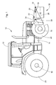
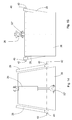
- an inventive agricultural vehicle 10 is shown in the form of a tractor 12.
- the tractor 12 has a vehicle frame 14 supported by wheels 20 suspended from a front axle 16 and a rear axle 18.
- a front three-point hitch 22 Arranged on the vehicle frame 14 at the front of the vehicle 10 is a front three-point hitch 22, which is detachably fastened, in particular bolted, to the vehicle frame 14 via a mounting frame 24 and extends forward beyond the vehicle frame 14.
- the front three-point hitch 22 has a centerline to the vehicle 10 and in the upper region of the three-point hitch 22 arranged upper link 26 and two laterally to the top link 26 and the lower portion of the three-point hitch 22 arranged lower link 28, which are each pivotally mounted on the mounting frame 24. Between the lower links 28 and the mounting frame 22 each extend a lifting strut 30, which hold the lower link 28 in a desired pivotal position to the mounting frame 22.
- the lifting rods 30 can as Hydraulic cylinder may be formed so that the lower link 28 are hydraulically adjustable in height or angularly adjustable or pivotable.
- the upper and lower links 26, 28 are each provided with articulation points 32 and catch hooks 34, to which a designed for the Dreitician working device in the form of a Ballastiervorraum 36 according to the invention is coupled or attached.
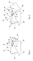
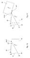
- the ballasting devices 36 described below each have a ballast weight 38, which is received on laterally extending receiving bolt 40 (laterally in the sense of transverse to a vehicle longitudinal axis) and pivotable about pivot means about a defined by the locating pin 40 pivot axis 42 of the lower links of the three-point hitch or pivotally coupled to the three-point hitch 22.
- the pivot axis 42 is arranged on Ballastiermay 38 such that at a basic position of the ballast 38 (retracted, close to the vehicle, lower position of Ballastierstructs) the pivot axis above and in the direction of travel in front of the center of gravity S Ballastierparticularlys 38.
- the link 54 is also designed to be adjustable in length, preferably as a hydraulic cylinder, wherein the hydraulic cylinder is pivotally connected on the cylinder side with the steering plate 44 at the pivot point 46 and the rod side pivotally connected to the receiving bearing 52.
- the second pivot point 48 of the steering plate 44 is located centrally to the ballast weight 38 and coaxial with the pivot axis 42 and connects the Ballastiermay 38 pivotally connected to the steering plate 44.
- the steering plate 44 directly via a connecting pin 56 through which the receiving bolts 40 are formed simultaneously pivotally connected to the ballast weight 38. It is quite conceivable to form the connecting bolt 56 and the locating bolt 40 separately from each other.
- connecting means is a connecting pin 58 which connects the upper link 26 and the steering plate 44 pivotally with each other.
- the upper link 26 is fork-shaped, see FIGS. 5 and 6 wherein the blazing end is connected to the steering plate 44.
- the steering plate 44 has two opposite baffle sides 44 ', 44 "which are arranged on the inside of the fork of the upper link 26.
- the fork of the upper link 26 is provided so that the handlebar 54 and the steering plate 44 can swing out on actuation of the Ballastiervoriques 36, since they claim a corresponding range of motion.
- a recess 60 which also extends symmetrically to a vehicle longitudinal center axis (ie centrally) into the interior of the Ballastierparticularlys 38.
- the recess 60 is dimensioned such that both the steering plate 44 and 44 'and 44 "as well as the upper link 26 and its fork in the recess 60 can move freely when pivoting the Ballastier wishess 38 or when pressing the Ballastier 36.
- the Ballastierconstru 38 and the Dreiticianan monvorides 22 are formed or adapted to the design of the vehicle 10 that the Ballastiermay 38 moves in vehicle-near position as far as possible below the vehicle frame 14 and positioned and moved as close to the front axle 16 of the vehicle 10. In the off-vehicle upper position, the ballast weight 38 is in a position that has a substantially higher center of gravity than the vehicle-near lower position.
- the ball-and-cage device 36 can be operated in two stages by first extending the length-adjustable link 54. This results in that the ballast weight 38 is pivoted about its pivot axis 42 until the handlebar 54 has taken its full length.
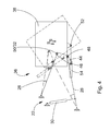
- the Ballastierthe 38 is pivoted (depending on the arrangement of the upper link 26, lower link 28, steering plate 44 and arm 54) to about 120 °, the center of gravity S of Ballastiermays 38 is shifted significantly upwards and forwards.
- the upper link 26, the lower link 28 and the steering plate 44 are held substantially in their positions and in turn hold the pivot axis fixed.
- the second stage is initiated (see FIG. 4 ) by moving the lower links 28 down.
- the second movement stage a further shift of the center of gravity S of Ballastiermays 38 can be achieved upwards, whereby additional ground clearance is obtained.
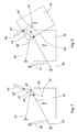
- a second embodiment will be described with reference to FIGS. 7 to 11 described, in which case the steering plate 44 and the length-adjustable arm 54 'have a different arrangement to the first embodiment.
- the pivot points 46, 48, 50 of the steering plate 44 and the receiving camp 52 of Ballastiermays 38 are designated respectively with 46 ', 48' 50 'and 52'. Otherwise, the above statements also apply to the second embodiment.
- the first pivot point 46 'of the steering plate 44 is here, see FIG. 7 bi 9, arranged centrally to the Ballastiermay 38 and coaxial with the pivot axis 42 and connecting the Ballastierthe 38 pivotally connected to the steering plate 44. Further, the second pivot point 48 'with the upper link 26 of the three-point hitch 22 is connected.
- the third pivot point 50 'of the steering plate 44 is connected to the length-adjustable arm 54, which also connects the Ballastiermay 38 at the receiving bearing 52' with the steering plate 44.
- the receiving bearing 52 ' is arranged inside the ballast weight 38 in the region of the recess 60.
- the handlebar 54 characterized in its normal position on an extended position. The adjustment of the ballasting device 36 and the Ballastiermays 38 takes place here also in two stages.
- a third embodiment will be described with reference to FIGS. 12 to 15 described, with a one-step adjustment of the ballasting device 36 is formed here.
- This is achieved in that the steering plate 44 present in the first and second embodiments is omitted, so that no further pivoting of the ballast weight 38 can be achieved by lowering or raising the lower link.
- the upper link 26 is designed as a length-adjustable handlebar, for example as a hydraulic cylinder or according to one of the alternatives mentioned in the above embodiments (servomotor etc.).
- a steering plate 44 accounts correspondingly the pivot points 46, 48, 50 and 46 ', 48', 50 '.
- the arrangement of the pivot shaft 42 and the arrangement of the pivot shaft 42 defining receiving bolt 40 is carried out according to the above embodiments.
- the receiving camp 52 " is arranged in the direction of travel in front of the pivot shaft 42 at the top of the Ballastier wishess 38 and connected to the upper link 26, the upper link occupies an extended position in its normal position ( FIG. 12 ).
- By retracting the upper link 26 ( FIG. 13 ) now takes place a pivoting of the ballast weight 38 about the pivot axis 42, wherein the center of gravity S of Ballastier wishess 38 moves forward and upward, as in FIG. 13 becomes clear.
- a fourth embodiment will be described with reference to FIGS. 16 to 19 described, here also a single-stage adjustment of the ballasting device 36 is formed.
- the fourth embodiment differs from the preceding (third) embodiment only in that the receiving bearing 52 ''', here in the direction of travel behind the pivot shaft 42 at the top of Ballastier wishess 38 is arranged and the upper link assumes a retracted position in its normal position ( figure 16 ).
- the upper link 26 By extending the upper link 26 ( FIG. 17 ) now takes place a pivoting of the ballast weight 38 about the pivot axis 42, wherein the center of gravity S of Ballastier wishess 38 moves forward and upward, as in FIG. 17 becomes clear.
Abstract
Description
Die Erfindung betrifft eine Ballastiervorrichtung für ein landwirtschaftliches Fahrzeug, mit einem Ballastiergewicht, welches seitliche Aufnahmebolzen aufweist, die koaxial zu einer gemeinsamen Schwenkachse ausgerichtet sind, wobei die Ballastiervorrichtung an den Aufnahmebolzen von den Unterlenkern einer Dreipunktanhängevorrichtung aufnehmbar ist und das Ballastiergewicht in einem aufgenommenen Zustand der Ballastiervorrichtung von einer in Bezug auf den Schwerpunkt des Ballastiergewichts fahrzeugnahen Position in eine fahrzeugferne Position bewegbar ist. Ferner betrifft die Erfindung ein landwirtschaftliches Fahrzeug mit einer solchen Ballastiervorrichtung.The invention relates to a ballasting device for an agricultural vehicle, having a ballast weight, which has lateral locating pins, which are aligned coaxially to a common pivot axis, wherein the ballast is receivable on the locating bolt of the lower links of a three-point hitch and the Ballastiergewicht in a recorded state of Ballastiervorrichtung is movable from a position close to the vehicle relative to the center of gravity of the ballast weight in a vehicle-distant position. Furthermore, the invention relates to an agricultural vehicle with such a ballast device.
Es ist bekannt, dass landwirtschaftliche Schlepper, bei Arbeiten mit schweren Heck-Anbaugeräten, wie z.B. mit einem Pflug, zum Ausgleich mit einer Zusatzmasse bzw. Zusatzgewicht oder Ballastiergewicht am vorderen Ende des Schleppers bestückt werden. Eine derartige Ballastierung mit einem Ballastiergewicht kann mit einem einteiligen massiven Gewicht (z.B. 900 kg), oder auch durch mehrere kleinere Einzelgewichte (z.B. ä 50 kg) erfolgen. Üblicherweise sind die Ballastiergewichte an einem vorgegebenen Platz am vorderen Teil des Fahrzeugrumpfs angeordnet und fest installiert. Es ist oftmals mit erheblichem Aufwand verbunden und nicht ohne aufwändige Gerätschaften (Gabelstapler, Kran, Hubvorrichtung etc.) realisierbar, die Ballastiergewichte zu montieren bzw. zu demontieren, so dass die Ballastiergewichte nur wenige bzw. aufwändige Möglichkeiten bieten, die durch eine Ballastierung auf die Vorderachse aufgebrachte Zusatzlast zu variieren bzw. den sich ändernden Gegebenheiten bzw. Arbeitsbedingungen optimal anzupassen. Dies führt in der Praxis oftmals dazu, dass meist mit dem gleichen Ballastiergewicht bzw. mit der gleichen Zusatzmasse gearbeitet wird und dadurch der Schlepper nicht optimal ballastiert unterwegs ist. Dies kann ferner weitere Nachteile mit sich führen: Einen grundsätzlich höheren Kraftstoffverbrauch sowie eine geringere Zuladung bei hochballastigen Ballastiergewichten. Eine größere Fahrzeuglänge und eine damit verbundene geringere Wendigkeit bei Ballastiergewichten die am vorderen Teil des Fahrzeugrumpfs angeordnet sind. Einen relativ hohen Schwerpunkt des Fahrzeugs, da das Ballastiergewicht in der Regel vor dem Fahrzeugrumpf oberhalb der Fahrzeugachse angeordnet ist. Ein damit verbundenes hohes Gefahrenpotential für Unfallgegner bei Straßenfahrt, insbesondere für Pkw's, da das Ballastiergewicht in der Regel relativ hoch im Vergleich zu einem Pkw angebracht ist, so dass diese entweder überrollt oder in ungeschützten Bereichen (Fenster, bzw. Dach) durch das Ballastiergewicht gerammt werden.It is known that agricultural tractors, when working with heavy rear attachments, such as a plow, are equipped to compensate with an additional mass or additional weight or Ballastiergewicht at the front end of the tractor. Such a ballast with a ballast weight can be done with a one-piece massive weight (eg 900 kg), or by several smaller individual weights (eg ä 50 kg). Usually, the ballast weights are arranged at a predetermined place on the front part of the vehicle body and fixedly installed. It is often associated with considerable effort and not without expensive equipment (forklift, crane, lifting device, etc.) feasible to mount the ballast weights or dismantle, so that the Ballastiergewichte offer only a few or costly options that by ballasting on the Front axle applied additional load to vary or optimally adapt to changing circumstances or working conditions. In practice, this often leads to the fact that one usually works with the same ballast weight or with the same additional mass and thus the tractor is not optimally ballasted on the way. This can also lead to other disadvantages: A fundamentally higher fuel consumption and a lower payload for high ballast ballast weights. A larger vehicle length and associated lower maneuverability with ballast weights on the front part of the vehicle body are arranged. A relatively high center of gravity of the vehicle, since the ballast weight is usually arranged in front of the vehicle body above the vehicle axle. An associated high risk potential for accident opponents when driving on the road, especially for cars, since the Ballastiergewicht is usually relatively high compared to a car mounted so that either overrun or rammed in unprotected areas (windows, or roof) by the Ballastiergewicht become.
Im Stand der Technik sind Lösungen bekannt, mit denen versucht wird diese Probleme zu bekämpfen. So ist es beispielsweise bekannt, eine Fronthydraulik, insbesondere Fronthitch, einzusetzen, mit der ein Zusatzgewicht bzw. ein Ballastiergewicht zur Ballastierung einfach und bequem im Bedarfsfall aufgenommen werden kann. Derartige Fronthydrauliken ermöglichen jedoch nur eine festgelegte Lage des Ballastiergewichts, so dass die oben genannten Probleme nur teilweise berücksichtigt werden.In the prior art solutions are known, which is trying to combat these problems. Thus, it is known, for example, to use front hydraulics, in particular Fronthitch, with which an additional weight or a ballasting weight for ballasting can be accommodated simply and conveniently in case of need. However, such front hydraulics allow only a fixed position of the ballast weight, so that the above-mentioned problems are only partially taken into account.
Es ist ferner bekannt, eine Ballastierung durch ein Zusatzgewicht bzw. Ballastiergewicht dahingehend den geforderten und vorherrschenden Arbeitsbedingungen anzupassen, dass die Anordnung des Gewichts am Fahrzeug variabel ist und insbesondere eine Verschiebung des Gewichts in Längsrichtung des Fahrzeugs ermöglicht wird.It is also known to adapt ballasting by an additional weight or ballasting weight to the required and prevailing working conditions such that the arrangement of the weight on the vehicle is variable and in particular a shift of the weight in the longitudinal direction of the vehicle is made possible.
Eine derartige verstellbare Vorrichtung an einem landwirtschaftlichen Schlepper offenbart die
So offenbart die
Ferner offenbart die
Die der Erfindung zugrunde liegende Aufgabe wird darin gesehen, eine landwirtschaftliche Maschine der eingangs genannten Art anzugeben, durch welches die vorgenannten Probleme überwunden werden.Further, the
The object underlying the invention is seen to provide an agricultural machine of the type mentioned, by which the aforementioned problems are overcome.
Die Aufgabe wird erfindungsgemäß durch die Lehre des Patentanspruchs 1 und 7 gelöst. Weitere vorteilhafte Ausgestaltungen und Weiterbildungen der Erfindung gehen aus den Unteransprüchen hervor.The object is achieved by the teaching of claim 1 and 7. Further advantageous embodiments and modifications of the invention will become apparent from the dependent claims.
Erfindungsgemäß wird eine Ballastiervorrichtung der eingangs genannten Art derart ausgebildet, dass die Schwerpunktlage des Ballastiergewichts in der fahrzeugnahen Position unterhalb der Schwenkachse ist und Schwenkmittel vorgesehen sind, durch die das Ballastiergewicht derart um die Schwenkachse verschwenkbar ist, dass es aus der fahrzeugnahen Position in die fahrzeugferne Position bewegbar ist, wobei das Ballastiergewicht in der fahrzeugnahen Position eine tiefere Schwerpunktlage einnimmt als in der fahrzeugfernen Position. Eine erfindungsgemäße Ballastiervorrichtung ermöglicht, durch Längsverlagerung des Ballastiergewichts, die auf die Vorderräder des Fahrzeugs wirkende Zusatzmasse einzustellen und optimal den vorherrschenden Betriebsbedingungen anzupassen. Dadurch kann zur Ballastierung eine insgesamt geringere Gesamtmasse eingesetzt werden. Dadurch, dass das Ballastiergewicht beweglich ist, kann es auch auf einfache Weise in eine Aufbockstellung gebracht werden. Das erleichtert sowohl das Abstellen bzw. Abmontieren als auch das Aufsetzen bzw. Anmontieren des Ballastiergewichts. Vorteilhafterweise ist die Ballastiervorrichtung an eine Dreipunktanhängevorrichtung eines landwirtschaftlichen Schleppers koppelbar. Damit ist eine einfache Handhabung des Ballastiergewichts gegeben, wobei die Ballastiervorrichtung an den am Ballastiergewicht vorgesehenen Aufnahmebolzen durch die Unterlenker der Dreipunktanhängevorrichtung aufgenommen werden kann. Durch die Schwerpunktlage des Schwerpunkts des Ballastiergewichts, die unterhalb der durch die Aufnahmebolzen definierten Schwenkachse des Ballastiergewichts angeordnet ist, wird ermöglicht, dass durch Verschwenken des Ballastiergewichts nach vorn um die Schwenkachse eine Schwerpunktverlagerung des Gewichts von einer unteren fahrzeugnahen Position in eine obere fahrzeugferne Position realisierbar ist. Damit sind beispielsweise bei Transportfahrten ohne großen Aufwand höhere Zuladungen möglich und es wird ein insgesamt geringerer Kraftstoffverbrauch erzielt. Durch die niedrige Schwerpunktlage des Ballastiergewichts in der fahrzeugnahen Position wird zudem ein Personen- und Fahrzeugschutz im Straßenverkehr erhöht, da Hindernisse bei Kollisionen, z.B. bei einem Unfall mit einem Pkw, in einer tieferen Position gerammt werden, so dass auch ein Überrollen vermieden werden kann. Die fahrzeugnahe Position des Ballastiergewichts bietet eine maximale Wendigkeit des Fahrzeugs, da das vorstehende Ballastiergewicht nicht so weit herausragt. Durch die fahrzeugnahe Position mit tiefer Schwerpunktlage des Ballastiergewichts wird auch die Fahrsicherheit bei Kurvenlage oder Hanglage des Fahrzeugs erhöht.According to the invention, a ballast device of the type mentioned above is formed such that the center of gravity of Ballastiergewichts in the vehicle-near position below the pivot axis and pivot means are provided by the Ballastiergewicht is pivotable about the pivot axis that it from the vehicle-proximate position in the vehicle-distant position is movable, wherein the ballast weight occupies a lower center of gravity position in the vehicle-near position than in the vehicle-distant position. A ballasting device according to the invention makes it possible, by longitudinal displacement of the ballast weight, to adjust the additional mass acting on the front wheels of the vehicle and to optimally adapt it to the prevailing operating conditions. Thereby can be used for ballasting a total lower total mass. The fact that the Ballastiergewicht is movable, it can also be easily brought into a jacking position. This facilitates both the parking or dismounting as well as the placement or Anmontieren the Ballastiergewichts. Advantageously, the ballasting device can be coupled to a three-point hitch of an agricultural tractor. This is an easy handling of Ballastiergewichts given, the Ballastiervorrichtung can be added to the provided on Ballastiergewicht receiving bolt through the lower links of the three-point hitch. By the center of gravity of the center of gravity of the ballast weight, which is arranged below the pivot axis of the Ballastiergewichts defined by the locating bolts, it is possible by swinging the Ballastiergewichts forward about the pivot axis a center of gravity of the weight from a lower vehicle-near position into an upper vehicle-distant position can be realized , Thus, for example, during transport trips without much effort higher payloads are possible and it is achieved an overall lower fuel consumption. Due to the low center of gravity of the ballast weight in the vehicle-near position also a personal and vehicle protection is increased in traffic, as obstacles in collisions, for example in an accident with a car, are rammed in a lower position, so that overrunning can be avoided. The vehicle-near position of the ballast weight provides maximum maneuverability of the vehicle, since the above ballast weight does not protrude so far. The close-to-vehicle position with low center of gravity of the ballast weight also increases driving safety when the vehicle is cornering or sloping.
Vorzugsweise weisen die Schwenkmittel ein Aufnahmelager am Ballastiergewicht auf, an das ein längenverstellbarer Lenker drehbar koppelbar ist, derart, dass durch eine Längenänderung des Lenkers ein Verschwenken des Ballastiergewichts erzielbar ist. Durch Längenveränderung des längenverstellbaren Lenkers wird das Aufnahmelager am Ballastiergewicht in einem festen Abstand zu den Aufnahmebolzen bzw. zur Schwenkachse verschoben, so dass eine Rotationsbewegung des Ballastiergewichts um die Schwenkachse eingeleitet wird. Dadurch verschiebt sich der Schwerpunkt des Ballastiergewichts in einem festen Abstand (Radius) zur Schwenkachse, so dass bei aufgenommenen Aufnahmebolzen, beispielsweise wenn diese durch die Unterlenker einer Dreipunktanhängevorrichtung aufgenommen sind, eine Schwerpunktverlagerung des Ballastiergewichts aus einer unteren fahrzeugnahen Position in eine obere fahrzeugferne Position stattfindet.Preferably, the pivot means have a receiving bearing on Ballastiergewicht to which a length-adjustable handlebar is rotatably coupled, such that a pivoting of the Ballastiergewichts can be achieved by a change in length of the handlebar. By Length change of the length-adjustable arm, the receiving camp is moved to Ballastiergewicht at a fixed distance to the receiving pin or to the pivot axis, so that a rotational movement of Ballastiergewichts is initiated about the pivot axis. As a result, the center of gravity of the ballast weight shifts at a fixed distance (radius) to the pivot axis, so that when recording bolts recorded, for example, if they are taken by the lower link of a Dreipunktanhängevorrichtung, a shift in gravity Ballastiergewicht takes place from a lower position close to the vehicle in an upper position away from the vehicle.
In einer bevorzugten Ausbildung der Erfindung ist das Aufnahmelager der Ballstiervorrichtung derart ausgebildet, dass daran ein längenverstellbarer Lenker einer Dreipunktanhängevorrichtung, insbesondere ein sogenannter Oberlenker, koppelbar ist. Dadurch wird ermöglicht, dass die genannte Ballastiervorrichtung mit einer Dreipunktanhängevorrichtung üblicher Bauart kompatibel und an diese koppelbar ist. Bei angekoppelter Ballastiervorrichtung wird durch Längenverstellung des Oberlenkers, wie oben bereits beschrieben, eine Rotationsbewegung des Ballastiergewichts um die Schwenkachse eingeleitet. Die Schwenkachse wird dabei durch die seitlichen Aufnahmebolzen, die von den Unterlenkern der Dreipunktanhängevorrichtung gehalten werden, definiert.In a preferred embodiment of the invention, the receiving bearing of the ball animal device is designed such that a length-adjustable arm of a three-point hitch, in particular a so-called upper link, can be coupled thereto. This makes it possible that said ballast is compatible with a three-point hitch of conventional design and can be coupled to this. When coupled ballast is introduced by length adjustment of the upper link, as already described above, a rotational movement of Ballastiergewichts about the pivot axis. The pivot axis is defined by the lateral locating bolts, which are held by the lower links of the three-point hitch.
In einer weiteren bevorzugten Ausbildung weisen die Schwenkmittel neben dem Aufnahmelager am Ballastiergewicht, wenigstens ein Lenkblech mit wenigstens drei Anlenkpunkten und einen längenverstellbaren Lenker auf, wobei das Lenkblech an einem (ersten) Anlenkpunkt über den längenverstellbaren Lenker drehbar mit dem Aufnahmelager und an einem weiteren (zweiten) Anlenkpunkt koaxial zur Schwenkachse drehbar mit dem Ballastiergewicht verbunden ist, derart, dass durch eine Längenänderung des längenverstellbaren Lenkers ein Verschwenken des Ballastiergewichts gegenüber dem Lenkblech erzielbar ist, wobei das Lenkblech an einem weiteren (dritten) Anlenkpunkt mit einem Lenker einer Dreipunktanhängevorrichtung, vorzugsweise dem Oberlenker, koppelbar ist. Dadurch, dass der zweite Anlenkpunkt des Lenkblechs koaxial zu der Schwenkachse bzw. zu den Aufnahmebolzen angeordnet ist, wird bei Ankopplung der Ballastiervorrichtung an eine Dreipunktanhängevorrichtung die Position des zweiten Anlenkpunkts koaxial zu den Aufnahmebolzen der Ballastiervorrichtung durch die Unterlenker festgelegt, bzw. vorgegeben. Sofern diese verstellbar (höhen- oder längenverstellbar) ausgebildet sind, kann durch Verstellen der Unterlenker die Schwenkachse der Ballastiervorrichtung und damit auch die Position des zweiten Aufnahmepunkts variiert bzw. verstellt bzw. verschoben werden. Ferner wird bei Ankopplung der Ballastiervorrichtung an eine Dreipunktanhängevorrichtung auch die Position des dritten Anlenkpunkts des Lenkblechs durch den Lenker der Dreipunkanhängevorrichtung (insbesondere dem Oberlenker) festgelegt, wobei die Position des dritten Anlenkpunktes durch Verstellen der Unterlenker variierbar bzw. verstellbar bzw. verschiebbar ist. Somit können die Positionen des zweiten und dritten Anlenkpunktes (und damit auch die Position des ersten Anlenkpunktes) bei angekoppelter Ballastiervorrichtung, durch Verstellen der Unterlenker, in Bezug auf einen mit einer Dreipunktanhängevorrichtung bestückten Fahrzeugrahmen, definiert variiert bzw. verstellt bzw. verschoben werden. Ferner ist es auch möglich, den mit dem dritten Anlenkpunkt verbundenen Lenker längenverstellbar zu gestalten, um weitere Möglichkeiten zur Veränderung der Positionen der Anlenkpunkte des Lenkblechs zu schaffen.In a further preferred embodiment, the pivot means next to the receiving camp on Ballastiergewicht, at least one steering plate with at least three articulation points and a length-adjustable handlebars, wherein the steering plate at a (first) pivot point on the length-adjustable arm rotatably connected to the receiving camp and at another (second ) Anlenkpunkt coaxial with the pivot axis rotatably connected to the Ballastiergewicht, such that by a change in length of the length-adjustable handlebar pivoting of Ballastiergewichts with respect to the steering plate is achieved, wherein the steering plate at a further (third) pivot point a link of a three-point hitch, preferably the upper link, can be coupled. Characterized in that the second pivot point of the steering plate is arranged coaxially to the pivot axis or to the locating bolt, the position of the second pivot point coaxial with the locating pin of the ballast is determined by the lower link when coupling the ballast to a three-point hitch. If these are adjustable (adjustable in height or length), the pivot axis of the ballasting device and thus also the position of the second receiving point can be varied or displaced or displaced by adjusting the lower links. Further, when coupling the ballast to a three-point hitch and the position of the third pivot point of the steering plate by the handlebars of Dreipunkanhängevorrichtung (in particular the upper link) set, the position of the third pivot point is variable by adjusting the lower link or adjustable or displaceable. Thus, the positions of the second and third articulation point (and thus also the position of the first articulation point) with coupled ballast, by adjusting the lower link, with respect to a vehicle equipped with a three-point hitch vehicle frame, defined varied or displaced or displaced. Furthermore, it is also possible to make the arm connected to the third articulation point adjustable in length in order to create further possibilities for changing the positions of the articulation points of the steering plate.
Vorzugsweise ist (bzw. sind) der (die) längenverstellbare(n) Lenker als Aktuator, insbesondere als Hydraulikzylinder, ausgebildet. Es ist jedoch auch denkbar eine andere, beispielsweise elektrische, mechanische oder pneumatische Betätigungsart eines Zylinders zu wählen. So kann der Aktuator als Elektromotor, beispielsweise Spindelmotor, ausgebildet sein. Auch eine entsprechende Anordnung mit einem Seilzug ist denkbar, um die Betätigung rein mechanisch zu gestalten. Vorzugsweise ist der Aktuator derart angelenkt, dass durch Betätigen des Aktuators im Zusammenspiel der Ballastiervorrichtung mit den Lenkern der Dreipunktanhängevorrichtung ein geführtes Bewegen des Ballastiergewichts ausgelöst werden kann. Dadurch wird gewährleistet, dass eine Bedienperson durch Fernsteuerung ein Variieren bzw. Verschieben bzw. Verstellen des Ballastiergewichts realisieren und auch bei sich ändernden Betriebsbedingungen schnell reagieren und die Ballastierung optimieren kann.Preferably, the (s) length-adjustable handlebar (s) are / is designed as an actuator, in particular as a hydraulic cylinder. However, it is also conceivable to choose another, for example, electrical, mechanical or pneumatic actuation of a cylinder. Thus, the actuator may be designed as an electric motor, for example a spindle motor. A corresponding arrangement with a cable is conceivable to make the operation purely mechanical. Preferably, the actuator is articulated such that by operating the actuator in the interaction of the Ballastiervorrichtung with the handlebars of the three-point hitch a guided moving the Ballastiergewichts can be triggered. This ensures that an operator by remote control a varying or moving or adjusting the Ballastiergewichts realize and react quickly even under changing operating conditions and optimize the ballast.
In einer bevorzugten Ausbildung der Erfindung erstrecken sich die Schwenkmittel wenigstens teilweise durch eine am Ballastiergewicht eingebrachte Aussparung, wobei die Aussparung vorzugsweise mittig zu einer Mittellängsachse des Fahrzeugs bzw. Fahrzeugrahmens ausgebildet ist. Je nach Ausführungsform können sich die Schwenkmittel auch wenigstens teilweise durch eine Aussparung erstrecken, die am Fahrzeugrumpf und/oder an einem Fahrzeugrahmen und/oder an einer am Fahrzeugrumpf oder Fahrzeugrahmen ausgebildeten Aufnahmevorrichtung eingebracht ist, wobei diese ebenfalls entsprechend mittig ausgebildet ist. Durch die Aussparung bzw. Aussparungen wird bzw. werden eine möglichst kompakte Bauweise der Schwenkmittel, insbesondere des Lenkblechs im Zusammenspiel mit dem oder den längenverstellbaren Lenker bzw. Lenkern, erzielt, da die Schwenkmittel im Wesentlichen innerhalb der Aussparung ihre Schwenkbewegungen ausführen. Die mittige Anordnung der Aussparung sorgt für eine möglichst symmetrische Gewichtsverteilung des Ballastiergewichts bzw. der gesamten Ballastiervorrichtung.In a preferred embodiment of the invention, the pivot means extend at least partially through a recess introduced on the ballast weight, wherein the recess is preferably formed centrally to a central longitudinal axis of the vehicle or vehicle frame. Depending on the embodiment, the pivoting means may also extend at least partially through a recess which is introduced on the vehicle body and / or on a vehicle frame and / or on a receiving device formed on the vehicle body or vehicle frame, wherein this is likewise formed centrally. Through the recess or recesses is as compact as possible construction of the pivot means, in particular of the steering plate in conjunction with the length-adjustable handlebar or handlebars, achieved because the pivot means essentially execute their pivotal movements within the recess. The central arrangement of the recess ensures symmetrical as possible weight distribution of Ballastiergewichts or the entire ballast.
Ferner umfasst eine weitere Ausbildung der Erfindung ein landwirtschaftliches Fahrzeug, insbesondere Schlepper, mit einem Fahrzeugrumpf oder Fahrzeugrahmen, einer am vorderen Teil des Fahrzeugrumpfs befestigten Dreipunktanhängevorrichtung und einer Ballastiervorrichtung, wobei die Ballastiervorrichtung ein Ballastiergewicht mit seitlichen Aufnahmebolzen aufweist, die koaxial zu einer gemeinsamen Schwenkachse ausgerichtet sind, wobei die Ballastiervorrichtung an den Aufnahmebolzen von den Unterlenkern der Dreipunktanhängevorrichtung aufgenommen ist und das Ballastiergewicht in Bezug auf den Schwerpunkt des Ballastiergewichts von einer fahrzeugnahen Position in eine fahrzeugferne Position bringbar ist. Die Ballastiervorrichtung ist, wie oben bereits ausgeführt, derart ausgebildet, dass die Schwerpunktlage des Ballastiergewichts in der fahrzeugnahen Position unterhalb der Schwenkachse ist und Schwenkmittel vorgesehen sind, durch die das Ballastiergewicht derart um die Schwenkachse verschwenkbar ist, dass es aus der fahrzeugnahen Position in die fahrzeugferne Position bringbar ist, wobei das Ballastiergewicht in der fahrzeugnahen Position eine tiefere Schwerpunktlage einnimmt als in der fahrzeugfernen Position.Further, another embodiment of the invention includes an agricultural vehicle, in particular a tractor, with a vehicle body or frame, a three-point hitch attached to the front of the vehicle body, and a ballast, the ballast having a ballast weight with lateral locating pins coaxially aligned with a common pivot axis wherein the ballasting device is received on the locating bolt of the lower links of the three-point hitch and the Ballastiergewicht with respect to the center of gravity of the ballast weight from a vehicle-near position in a vehicle-remote position can be brought. The Ballastiervorrichtung is, as already stated above, designed such that the center of gravity of Ballastiergewichts in the vehicle-near position below the pivot axis and pivot means are provided by the Ballastiergewicht is pivotable about the pivot axis, that it from the vehicle-proximate position in the vehicle distant Position can be brought, wherein the ballast weight occupies a lower center of gravity position in the vehicle-near position than in the vehicle-distant position.
Weitere bevorzugte Ausbildungen eines landwirtschaftlichen Fahrzeugs, insbesondere Schleppers, sind gemäß oben bereits beschriebener Ausführungen einer Ballastiervorrichtung entsprechend vorgesehen und sollen hier berücksichtigt sein.
Das Ballastiergewicht kann ferner derart ausgebildet sein, dass es in seiner fahrzeugnahen Position wenigstens teilweise unterhalb des Fahrzeugrumpfs angeordnet ist. Dadurch kann beispielsweise eine weitere Schwerpunktverlagerung nach unten erzielt und zum anderen das Hervorstehen des Ballastiergewichts vor dem Fahrzeugrumpf weiter reduziert werden, wodurch sich die oben genannten Vorteile in Bezug auf einen tiefen Schwerpunkt und auf eine maximale Wendigkeit noch stärker ausprägen können.Further preferred embodiments of an agricultural vehicle, in particular a tractor, according to the above-described embodiments of a ballast device are provided accordingly and should be taken into account here.
The ballast weight can also be designed such that it is arranged in its vehicle-proximate position at least partially below the vehicle body. As a result, for example, a further shift of the center of gravity can be achieved and, on the other hand, the protrusion of the ballast weight in front of the vehicle body can be further reduced, whereby the abovementioned advantages with regard to a low center of gravity and maximum maneuverability can be emphasized even more.
In seiner fahrzeugfernen Position kann das Ballastiergewicht beispielsweise auf gleiche Höhe wie der Fahrzeugrumpf und vor dem Fahrzeugrumpf angeordnet sein. Dadurch wird eine hohe Bodenfreiheit bei Feldarbeiten gewährleistet und eine maximale Lasterhöhung an der Vorderachse erzielt.In its vehicle-remote position, the ballast weight can be arranged, for example, at the same height as the vehicle body and in front of the vehicle body. This ensures a high ground clearance in field work and achieves a maximum load increase on the front axle.
In einer bevorzugten Ausgestaltung der Erfindung sind die Lenker der Ballastiervorrichtung bzw. der Dreipunktanhängevorrichtung über eine Arretiervorrichtung in den einstellbaren Stellungen arretierbar. Dadurch wird gewährleistet, dass das Ballastiergewicht sicher und vorzugsweise spielfrei in einer fahrzeugnahen oder auch fahrzeugfernen Position gehalten wird. Hierbei ist es möglich auch Positionen zwischen der fahrzeugnahen und der fahrzeugfernen Position arretierbar vorzusehen, so dass eine Ballastierung entsprechend feinabgestimmt durchgeführt werden kann. Vorzugsweise umfasst die Arretiervorrichtung, dass der oder die verstellbaren Lenker der Schwenkmittel bzw. der Dreipunktvorrichtung hydraulisch oder pneumatisch bzw. mechanisch bzw. elektrisch in einer bestimmten Stellung arretierbar sind, also gehalten bzw. blockiert werden können, so dass die verstellbaren Lenker in einer gehaltenen bzw. blockierten Stellung verweilen. Eine derartige Arretierung bzw. Blockierung kann an einem längenverstellbaren Lenker, der einen hydraulisch ausgebildeten Aktuator umfasst, beispielsweise hydraulisch erfolgen. Ein elektrisch betätigbarer Spindel- oder Schrittmotor als Aktuator kann beispielsweise durch entsprechende elektronische Steuersignale in seiner Position verharren und die Lenkeranordnung elektrisch blockieren.In a preferred embodiment of the invention, the handlebars of the ballast device or the three-point hitch device via a locking device in the adjustable positions can be locked. This ensures that the ballast weight safely and preferably free of play in a vehicle-near or vehicle-remote position is maintained. In this case, it is also possible to provide positions between the vehicle-proximate and the vehicle-distant position in a lockable manner so that ballasting can be carried out in a correspondingly fine-tuned manner. Preferably, the locking device comprises that the one or more adjustable links of the pivot means or the three-point device can be locked hydraulically or pneumatically or mechanically or electrically in a certain position, so can be held or blocked, so that the adjustable handlebars in a held or Stay locked position. Such a lock or blocking can be done on a length-adjustable handlebar, which includes a hydraulically formed actuator, for example hydraulically. An electrically operable spindle or stepper motor as an actuator can, for example, remain in its position by corresponding electronic control signals and electrically block the linkage arrangement.
Anhand der Zeichnungen, die mehrere Ausführungsbeispiele der Erfindung zeigen, werden nachfolgend die Erfindung sowie weitere Vorteile und vorteilhafte Weiterbildungen und Ausgestaltungen der Erfindung näher beschrieben und erläutert.With reference to the drawings, which show several embodiments of the invention, the invention and further advantages and advantageous developments and refinements of the invention are described and explained in more detail below.
Es zeigt:
- Fig. 1
- eine schematische Seitenansicht eines landwirtschaftlichen Fahrzeugs mit einer an eine Front-Dreipunktanhängevorrichtung gekoppelten Ballastiervorrichtung
- Fig. 2
- eine schematische Seitenansicht eines ersten erfindungsgemäßen Ausführungsbeispiels einer an eine Dreipunktanhängevorrichtung gekoppelten Ballastiervorrichtung in einer Grundstellung,
- Fig. 3
- eine schematische Seitenansicht der an eine Dreipunktanhängevorrichtung gekoppelten Ballastiervorrichtung aus
Figur 2 in einer Mittelstellung, - Fig. 4
- eine schematische Seitenansicht der an eine Dreipunktanhängevorrichtung gekoppelten Ballastiervorrichtung aus den
Figuren 2 oder 3 in einer Endstellung, - Fig. 5
- eine schematische Draufsicht der an eine Dreipunktanhängevorrichtung gekoppelten Ballastiervorrichtung aus den
Figuren 2 bis 4 in der Grundstellung, - Fig. 6
- eine schematische Frontansicht der an eine Dreipunktanhängevorrichtung gekoppelten Ballastiervorrichtung aus den
Figuren 2 bis 5 in der Grundstellung, - Fig. 7
- eine schematische Seitenansicht eines zweiten erfindungsgemäßen Ausführungsbeispiels einer an eine Dreipunktanhängevorrichtung gekoppelten Ballastiervorrichtung in einer Grundstellung,
- Fig. 8
- eine schematische Seitenansicht der an eine Dreipunktanhängevorrichtung gekoppelten Ballastiervorrichtung aus
Figur 7 in einer Mittelstellung, - Fig. 9
- eine schematische Seitenansicht der an eine Dreipunktanhängevorrichtung gekoppelten Ballastiervorrichtung aus den
Figuren 7 oder 8 in einer Endstellung, - Fig. 10
- eine schematische Draufsicht der an eine Dreipunktanhängevorrichtung gekoppelten Ballastiervorrichtung aus den
Figuren 7 bis 9 in der Grundstellung, - Fig. 11
- eine schematische Frontansicht der an eine Dreipunktanhängevorrichtung gekoppelten Ballastiervorrichtung aus den
Figuren 7 in der Grundstellung,bis 10 - Fig. 12
- eine schematische Seitenansicht eines dritten erfindungsgemäßen Ausführungsbeispiels einer an eine Dreipunktanhängevorrichtung gekoppelten Ballastiervorrichtung in einer Grundstellung,
- Fig. 13
- eine schematische Seitenansicht der an eine Dreipunktanhängevorrichtung gekoppelten Ballastiervorrichtung aus
Figur 12 in einer Endstellung - Fig. 14
- eine schematische Draufsicht der an eine Dreipunktanhängevorrichtung gekoppelten Ballastiervorrichtung aus
den Figuren 12 oder 13 in der Grundstellung, - Fig. 15
- eine schematische Frontansicht der an eine Dreipunktanhängevorrichtung gekoppelten Ballastiervorrichtung aus
den Figuren 12 in der Grundstellung,bis 14 - Fig. 16
- eine schematische Seitenansicht eines vierten erfindungsgemäßen Ausführungsbeispiels einer an eine Dreipunktanhängevorrichtung gekoppelten Ballastiervorrichtung in einer Grundstellung,
- Fig. 17
- eine schematische Seitenansicht der an eine Dreipunktanhängevorrichtung gekoppelten Ballastiervorrichtung aus
Figur 16 in einer Endstellung - Fig. 18
- eine schematische Draufsicht der an eine Dreipunktanhängevorrichtung gekoppelten Ballastiervorrichtung aus
den Figuren 16 oder 17 in der Grundstellung und - Fig. 19
- eine schematische Frontansicht der an eine Dreipunktanhängevorrichtung gekoppelten Ballastiervorrichtung aus
den Figuren 16 in der Grundstellung.bis 18
- Fig. 1
- a schematic side view of an agricultural vehicle with a coupled to a front three-point hitch ballast device
- Fig. 2
- a schematic side view of a first embodiment according to the invention of a coupled to a three-point hitch ballast device in a basic position,
- Fig. 3
- a schematic side view of coupled to a three-point hitch ballast from
FIG. 2 in a middle position, - Fig. 4
- a schematic side view of coupled to a three-point hitch ballast from the
FIGS. 2 or 3 in an end position, - Fig. 5
- a schematic plan view of the coupled to a three-point hitch ballast from the
FIGS. 2 to 4 in the basic position, - Fig. 6
- a schematic front view of coupled to a three-point hitch ballast from the
FIGS. 2 to 5 in the basic position, - Fig. 7
- FIG. 2 shows a schematic side view of a second exemplary embodiment according to the invention of a ballast device coupled to a three-point hitch device in a basic position, FIG.
- Fig. 8
- a schematic side view of coupled to a three-point hitch ballast from
FIG. 7 in a middle position, - Fig. 9
- a schematic side view of coupled to a three-point hitch ballast from the
FIGS. 7 or 8 in an end position, - Fig. 10
- a schematic plan view of the coupled to a three-point hitch ballast from the
FIGS. 7 to 9 in the basic position, - Fig. 11
- a schematic front view of coupled to a three-point hitch ballast from the
FIGS. 7 to 10 in the basic position, - Fig. 12
- FIG. 2 shows a schematic side view of a third exemplary embodiment of a ballast device coupled to a three-point hitch device in a basic position, FIG.
- Fig. 13
- a schematic side view of coupled to a three-point hitch ballast from
FIG. 12 in an end position - Fig. 14
- a schematic plan view of the coupled to a three-point hitch ballast from the
FIGS. 12 or 13 in the basic position, - Fig. 15
- a schematic front view of coupled to a three-point hitch ballast from the
FIGS. 12 to 14 in the basic position, - Fig. 16
- FIG. 2 shows a schematic side view of a fourth exemplary embodiment according to the invention of a ballast device coupled to a three-point hitch device in a basic position, FIG.
- Fig. 17
- a schematic side view of coupled to a three-point hitch ballast from
FIG. 16 in an end position - Fig. 18
- a schematic plan view of the coupled to a three-point hitch ballast from the
FIGS. 16 or 17 in the basic position and - Fig. 19
- a schematic front view of coupled to a three-point hitch ballast from the
FIGS. 16 to 18 in the basic position.
In der
Die Front-Dreipunktanhängevorrichtung 22 weist einen mittig zum Fahrzeug 10 und im oberen Bereich der Dreipunktanhängevorrichtung 22 angeordneten Oberlenker 26 sowie zwei seitlich zum Oberlenker 26 und im unteren Bereich der Dreipunktanhängevorrichtung 22 angeordnete Unterlenker 28 auf, die jeweils schwenkbar an dem Befestigungsrahmen 24 gelagert sind. Zwischen den Unterlenkern 28 und dem Befestigungsrahmen 22 erstrecken sich jeweils eine Hubstrebe 30, welche die Unterlenker 28 in einer gewünschten Schwenkposition zum Befestigungsrahmen 22 halten. Die Hubstreben 30 können als Hydraulikzylinder ausgebildet sein, so dass die Unterlenker 28 hydraulisch höhenverstellbar bzw. winkelverstellbar bzw. verschwenkbar sind. Die Ober- und Unterlenker 26, 28 sind jeweils mit Anlenkpunkten 32 bzw. Fanghaken 34 versehen, an die eine für die Dreipunktanhängevorrichtung ausgelegte Arbeitsvorrichtung in Form einer erfindungsgemäßen Ballastiervorrichtung 36 gekoppelt bzw. angehängt ist.The front three-
Anhand der
Die im Folgenden beschriebenen Ballastiervorrichtungen 36 weisen jeweils ein Ballastiergewicht 38 auf, welches über sich seitlich erstreckende Aufnahmebolzen 40 (seitlich im Sinne von quer zu einer Fahrzeuglängsachse) und über Schwenkmittel schwenkbar um eine durch die Aufnahmebolzen 40 definierte Schwenkachse 42 von den Unterlenkern der Dreipunktanhängevorrichtung aufgenommen wird bzw. schwenkbar an die Dreipunktanhängevorrichtung 22 gekoppelt ist. Die Schwenkachse 42 wird am Ballastiergewicht 38 derart angeordnet, dass bei einer Grundstellung der Ballastiervorrichtung 38 (eingefahrene, fahrzeugnahe, untere Position des Ballastiergewichts) die Schwenkachse oberhalb und in Fahrtrichtung vor dem Schwerpunkt S des Ballastiergewichts 38 liegt.The
In dem in den
Das Ballastiergewicht 38 und die Dreipunktanhängevorrichtung 22 sind derart ausgebildet bzw. an die Ausgestaltung des Fahrzeugs 10 angepasst, dass das Ballastiergewicht 38 in fahrzeugnaher Position bis möglichst unterhalb des Fahrzeugrahmens 14 bewegt bzw. positioniert und möglichst nah an die Vorderachse 16 des Fahrzeugs 10 bewegt wird. In der fahrzeugfernen, oberen Position ist das Ballastiergewicht 38 in einer Position, die einen wesentlich höheren Schwerpunkt aufweist als die fahrzeugnahe untere Position.The
Der Lenker 54 kann, als blockierbarer bzw. selbsthemmender Aktuator ausgebildet sein, so dass keine separate Arretiereinrichtung für die Ballastiervorrichtung 36 vorgesehen sein muss, sondern vielmehr die Arretierung hydraulisch erfolgt, wobei eine entsprechende hydraulische Ansteuerung für einen als Hydraulikzylinder ausgebildeten Lenker 54, derart vorgesehen ist, dass ein Hydraulikausfluss aus einer oder mehreren Kammern des Hydraulikzylinders durch ein oder mehrere Sperrventile blockierbar ist. Beispielsweise kann als Lenker 54 auch einen Spindelmotor (nicht gezeigt) als Aktuator vorgesehen sein, der ein entsprechend selbsthemmendes Gewinde aufweist.The
Wie in den
Ein zweites Ausführungsbeispiel wird anhand der
Ein drittes Ausführungsbeispiel wird anhand der
Ein viertes Ausführungsbeispiel wird anhand der
Auch wenn die Erfindung in Bezug auf die Ballastiervorrichtung 36 lediglich anhand von vier Ausführungsbeispielen beschrieben wurde, erschließen sich für den Fachmann im Lichte der vorstehenden Beschreibung sowie der Zeichnung viele verschiedenartige Alternativen, Modifikationen und Varianten, die unter die vorliegende Erfindung fallen.Although the invention has been described with reference to the
Claims (11)
Applications Claiming Priority (1)
| Application Number | Priority Date | Filing Date | Title |
|---|---|---|---|
| DE102008043698A DE102008043698A1 (en) | 2008-11-13 | 2008-11-13 | Ballasting device and agricultural vehicle with such |
Publications (3)
| Publication Number | Publication Date |
|---|---|
| EP2186713A2 true EP2186713A2 (en) | 2010-05-19 |
| EP2186713A3 EP2186713A3 (en) | 2010-07-21 |
| EP2186713B1 EP2186713B1 (en) | 2012-07-11 |
Family
ID=41664826
Family Applications (1)
| Application Number | Title | Priority Date | Filing Date |
|---|---|---|---|
| EP09175752A Active EP2186713B1 (en) | 2008-11-13 | 2009-11-12 | Ballast device and agricultural vehicle with such device |
Country Status (4)
| Country | Link |
|---|---|
| US (1) | US8201849B2 (en) |
| EP (1) | EP2186713B1 (en) |
| DE (1) | DE102008043698A1 (en) |
| ES (1) | ES2391245T3 (en) |
Cited By (1)
| Publication number | Priority date | Publication date | Assignee | Title |
|---|---|---|---|---|
| EP3636520A1 (en) | 2018-10-10 | 2020-04-15 | Deere & Company | Ballasting device and agricultural vehicle |
Families Citing this family (10)
| Publication number | Priority date | Publication date | Assignee | Title |
|---|---|---|---|---|
| JP6066808B2 (en) * | 2013-04-10 | 2017-01-25 | 株式会社クボタ | Work vehicle |
| BR102013033526B1 (en) * | 2013-12-26 | 2021-07-27 | Dynapac Do Brasil Indústria E Comércio De Máquinas Ltda. | MACHINE WEIGHT ADJUSTMENT SYSTEM |
| US9139059B1 (en) | 2014-05-07 | 2015-09-22 | Safe-T-Pull, Inc. | Tractor hitch |
| KR101766027B1 (en) * | 2015-08-21 | 2017-08-07 | 현대자동차주식회사 | Balance Maintain Apparatus and Control Method Of Vehicle |
| US10167027B2 (en) * | 2015-11-18 | 2019-01-01 | Oshkosh Corporation | Modular counterweight |
| US10066365B2 (en) * | 2016-01-22 | 2018-09-04 | Hpm—Hydraulic Performance Machines Srl | Public works vehicle provided with counterweight lifting system |
| US10293874B2 (en) | 2016-04-26 | 2019-05-21 | Agco Corporation | Self mounting ballast weight system |
| US9957001B1 (en) * | 2016-11-02 | 2018-05-01 | Deere & Company | Ballast assembly for a work vehicle |
| DE102018212931A1 (en) | 2018-08-02 | 2020-02-06 | Deere & Company | Harvester with a header and a support wheel |
| CN110629824A (en) * | 2019-09-23 | 2019-12-31 | 上海三一重机股份有限公司 | Counter weight device and excavator |
Citations (3)
| Publication number | Priority date | Publication date | Assignee | Title |
|---|---|---|---|---|
| US4322094A (en) | 1978-07-18 | 1982-03-30 | Jeune Bobard | Tractor load |
| DE3223990A1 (en) | 1982-06-26 | 1983-12-29 | Klöckner-Humboldt-Deutz AG, 5000 Köln | Farming tractor having a removable ballast weight |
| DE102005040954A1 (en) | 2005-05-31 | 2006-12-07 | Hans Wittrock Gmbh | Agricultural tractor ballasting device, has counter balance that is rotatably supported on arm at tractor around horizontal aligned rotational axle, which is aligned parallel to wheel axle of tractor |
Family Cites Families (19)
| Publication number | Priority date | Publication date | Assignee | Title |
|---|---|---|---|---|
| US2891681A (en) * | 1956-12-05 | 1959-06-23 | Caterpillar Tractor Co | Rotatable counterweight mechanism |
| US3902735A (en) * | 1974-06-03 | 1975-09-02 | Caterpillar Tractor Co | Hydraulic counterweight removal mechanism |
| US4081035A (en) * | 1977-01-31 | 1978-03-28 | J. I. Case Company | Tractor with ripper attachment having a combined tool bar and counterweight container |
| JPS58128938A (en) * | 1982-01-27 | 1983-08-01 | Mitsubishi Motors Corp | Specially equipped car |
| NL8302688A (en) * | 1983-07-28 | 1985-02-18 | Lely Nv C Van Der | AGRICULTURAL APPARATUS, IN PARTICULAR AN APPARATUS FOR THE SPREAD OF SPREADABLE MATERIAL. |
| DE3442557C2 (en) * | 1984-11-22 | 1986-12-11 | Deere & Co., Moline, Ill., US, Niederlassung Deere & Co. European Office, 6800 Mannheim | Connection and coupling device for front attachment to a work vehicle |
| IT212711Z2 (en) * | 1987-11-02 | 1989-08-28 | Same Spa | METALLIC FOR TRACTORS MASS BALLASTING DEVICE |
| US5156215A (en) * | 1991-07-01 | 1992-10-20 | Golden Sunlight Mines, Inc. | Counterweight assembly for crawler tractor |
| DE4409514C2 (en) * | 1993-10-09 | 1998-05-07 | Orenstein & Koppel Ag | Adjustable counterweight for a construction machine and hydraulic excavator, which is equipped with an adjustable counterweight |
| US5799806A (en) * | 1997-01-31 | 1998-09-01 | Skyjack Equipment Inc. | Lifting device with counterweight |
| US6227304B1 (en) * | 1999-03-01 | 2001-05-08 | Case Corporation | Upper hitch link |
| JP2000291070A (en) * | 1999-04-01 | 2000-10-17 | Sumitomo Constr Mach Co Ltd | Counter-weight attaching and detaching device for working machine |
| FR2814038B1 (en) * | 2000-09-15 | 2002-11-29 | Hubert Defrancq | LIFT DEVICE FOR A TRACTOR FOR ATTACHING AND DETECTING A MASS WITHOUT MANUAL INTERVENTION |
| JP2003056009A (en) * | 2001-08-20 | 2003-02-26 | Shin Caterpillar Mitsubishi Ltd | Swing-out type counterweight construction for motor vehicle |
| US20070221600A1 (en) * | 2003-03-11 | 2007-09-27 | Davis Daniel E | Pipelayer and method of loading pipelayer or excavator for transportation |
| US7686097B2 (en) * | 2005-08-31 | 2010-03-30 | Cnh America Llc | Three point hitch frame, draft arm and rear counterweight design |
| JP5122786B2 (en) * | 2005-11-18 | 2013-01-16 | 株式会社小松製作所 | Counterweight attachment / detachment device |
| FR2895211B1 (en) * | 2005-12-22 | 2009-11-20 | Kuhn Sa | AGRICULTURAL ENGINE COMPRISING AN IMPROVED COUPLING |
| DE102007045912A1 (en) * | 2007-09-26 | 2009-04-09 | Deere & Company, Moline | Agricultural vehicle |
-
2008
- 2008-11-13 DE DE102008043698A patent/DE102008043698A1/en not_active Withdrawn
-
2009
- 2009-11-12 ES ES09175752T patent/ES2391245T3/en active Active
- 2009-11-12 EP EP09175752A patent/EP2186713B1/en active Active
- 2009-11-12 US US12/616,923 patent/US8201849B2/en active Active
Patent Citations (3)
| Publication number | Priority date | Publication date | Assignee | Title |
|---|---|---|---|---|
| US4322094A (en) | 1978-07-18 | 1982-03-30 | Jeune Bobard | Tractor load |
| DE3223990A1 (en) | 1982-06-26 | 1983-12-29 | Klöckner-Humboldt-Deutz AG, 5000 Köln | Farming tractor having a removable ballast weight |
| DE102005040954A1 (en) | 2005-05-31 | 2006-12-07 | Hans Wittrock Gmbh | Agricultural tractor ballasting device, has counter balance that is rotatably supported on arm at tractor around horizontal aligned rotational axle, which is aligned parallel to wheel axle of tractor |
Cited By (2)
| Publication number | Priority date | Publication date | Assignee | Title |
|---|---|---|---|---|
| EP3636520A1 (en) | 2018-10-10 | 2020-04-15 | Deere & Company | Ballasting device and agricultural vehicle |
| US11186326B2 (en) | 2018-10-10 | 2021-11-30 | Deere & Company | Ballasting device and agricultural vehicle |
Also Published As
| Publication number | Publication date |
|---|---|
| ES2391245T3 (en) | 2012-11-22 |
| US8201849B2 (en) | 2012-06-19 |
| EP2186713B1 (en) | 2012-07-11 |
| DE102008043698A1 (en) | 2010-05-20 |
| US20100117346A1 (en) | 2010-05-13 |
| EP2186713A3 (en) | 2010-07-21 |
Similar Documents
| Publication | Publication Date | Title |
|---|---|---|
| EP2186713B1 (en) | Ballast device and agricultural vehicle with such device | |
| DE3439048C2 (en) | Power lift for a lifting device | |
| DE3912194C2 (en) | vehicle | |
| EP3793929B1 (en) | Vehicle crane comprising a movable adapter between the main boom and the main boom extension | |
| DE202012010545U1 (en) | Heavy-duty transport vehicle for transporting an elongate object | |
| EP1008284A2 (en) | Telescoping implement connection for motorized vehicle | |
| DE102012021613B4 (en) | Heavy-duty transport vehicle for transporting an elongate object | |
| DE19534695C2 (en) | Rear mower that can be attached to a tractor | |
| EP3143861B2 (en) | Agricultural mower and trailer and method for operating the mower | |
| DE19919309A1 (en) | Swivel device for support wheels | |
| EP2042410B1 (en) | Agricultural vehicle | |
| EP3242543B1 (en) | Agricultural implement having an auxiliary chassis | |
| EP2436260A1 (en) | Hay tedder for turning crops lying on the ground | |
| DE3218525C2 (en) | Embankment mower | |
| DE102013209740B4 (en) | Agricultural implement | |
| DE102012108904A1 (en) | Device mounting device of a work vehicle | |
| EP3636520B1 (en) | Ballasting device and agricultural vehicle | |
| DE19820377C1 (en) | Work vehicle with tiltable driver platform and tilting device | |
| EP4074156A1 (en) | Drawbar assembly for a towed agricultural machine | |
| EP4101275A1 (en) | Field working attachment | |
| DE3139936A1 (en) | Agricultural trailer implement | |
| EP4019301A1 (en) | Axle device with variable track width, special vehicle and use of the same | |
| EP0594160A1 (en) | Machine for use in tree nurseries, gardens and the like | |
| EP3669630B1 (en) | Support wheel unit for an agricultural harvester | |
| EP1782674B1 (en) | Mowing machine |
Legal Events
| Date | Code | Title | Description |
|---|---|---|---|
| PUAI | Public reference made under article 153(3) epc to a published international application that has entered the european phase |
Free format text: ORIGINAL CODE: 0009012 |
|
| AK | Designated contracting states |
Kind code of ref document: A2 Designated state(s): AT BE BG CH CY CZ DE DK EE ES FI FR GB GR HR HU IE IS IT LI LT LU LV MC MK MT NL NO PL PT RO SE SI SK SM TR |
|
| PUAL | Search report despatched |
Free format text: ORIGINAL CODE: 0009013 |
|
| AK | Designated contracting states |
Kind code of ref document: A3 Designated state(s): AT BE BG CH CY CZ DE DK EE ES FI FR GB GR HR HU IE IS IT LI LT LU LV MC MK MT NL NO PL PT RO SE SI SK SM TR |
|
| 17P | Request for examination filed |
Effective date: 20110121 |
|
| GRAP | Despatch of communication of intention to grant a patent |
Free format text: ORIGINAL CODE: EPIDOSNIGR1 |
|
| GRAS | Grant fee paid |
Free format text: ORIGINAL CODE: EPIDOSNIGR3 |
|
| GRAA | (expected) grant |
Free format text: ORIGINAL CODE: 0009210 |
|
| AK | Designated contracting states |
Kind code of ref document: B1 Designated state(s): AT BE BG CH CY CZ DE DK EE ES FI FR GB GR HR HU IE IS IT LI LT LU LV MC MK MT NL NO PL PT RO SE SI SK SM TR |
|
| REG | Reference to a national code |
Ref country code: GB Ref legal event code: FG4D Free format text: NOT ENGLISH |
|
| REG | Reference to a national code |
Ref country code: CH Ref legal event code: EP |
|
| REG | Reference to a national code |
Ref country code: AT Ref legal event code: REF Ref document number: 565953 Country of ref document: AT Kind code of ref document: T Effective date: 20120715 |
|
| REG | Reference to a national code |
Ref country code: IE Ref legal event code: FG4D Free format text: LANGUAGE OF EP DOCUMENT: GERMAN |
|
| REG | Reference to a national code |
Ref country code: DE Ref legal event code: R096 Ref document number: 502009004066 Country of ref document: DE Effective date: 20120830 |
|
| REG | Reference to a national code |
Ref country code: CH Ref legal event code: NV Representative=s name: E. BLUM & CO. AG PATENT- UND MARKENANWAELTE VSP |
|
| REG | Reference to a national code |
Ref country code: ES Ref legal event code: FG2A Ref document number: 2391245 Country of ref document: ES Kind code of ref document: T3 Effective date: 20121122 |
|
| REG | Reference to a national code |
Ref country code: NL Ref legal event code: VDEP Effective date: 20120711 |
|
| REG | Reference to a national code |
Ref country code: LT Ref legal event code: MG4D Effective date: 20120711 |
|
| PG25 | Lapsed in a contracting state [announced via postgrant information from national office to epo] |
Ref country code: HR Free format text: LAPSE BECAUSE OF FAILURE TO SUBMIT A TRANSLATION OF THE DESCRIPTION OR TO PAY THE FEE WITHIN THE PRESCRIBED TIME-LIMIT Effective date: 20120711 Ref country code: CY Free format text: LAPSE BECAUSE OF FAILURE TO SUBMIT A TRANSLATION OF THE DESCRIPTION OR TO PAY THE FEE WITHIN THE PRESCRIBED TIME-LIMIT Effective date: 20120711 Ref country code: IS Free format text: LAPSE BECAUSE OF FAILURE TO SUBMIT A TRANSLATION OF THE DESCRIPTION OR TO PAY THE FEE WITHIN THE PRESCRIBED TIME-LIMIT Effective date: 20121111 Ref country code: NO Free format text: LAPSE BECAUSE OF FAILURE TO SUBMIT A TRANSLATION OF THE DESCRIPTION OR TO PAY THE FEE WITHIN THE PRESCRIBED TIME-LIMIT Effective date: 20121011 Ref country code: LT Free format text: LAPSE BECAUSE OF FAILURE TO SUBMIT A TRANSLATION OF THE DESCRIPTION OR TO PAY THE FEE WITHIN THE PRESCRIBED TIME-LIMIT Effective date: 20120711 |
|
| PG25 | Lapsed in a contracting state [announced via postgrant information from national office to epo] |
Ref country code: PT Free format text: LAPSE BECAUSE OF FAILURE TO SUBMIT A TRANSLATION OF THE DESCRIPTION OR TO PAY THE FEE WITHIN THE PRESCRIBED TIME-LIMIT Effective date: 20121112 Ref country code: LV Free format text: LAPSE BECAUSE OF FAILURE TO SUBMIT A TRANSLATION OF THE DESCRIPTION OR TO PAY THE FEE WITHIN THE PRESCRIBED TIME-LIMIT Effective date: 20120711 Ref country code: PL Free format text: LAPSE BECAUSE OF FAILURE TO SUBMIT A TRANSLATION OF THE DESCRIPTION OR TO PAY THE FEE WITHIN THE PRESCRIBED TIME-LIMIT Effective date: 20120711 Ref country code: SI Free format text: LAPSE BECAUSE OF FAILURE TO SUBMIT A TRANSLATION OF THE DESCRIPTION OR TO PAY THE FEE WITHIN THE PRESCRIBED TIME-LIMIT Effective date: 20120711 Ref country code: SE Free format text: LAPSE BECAUSE OF FAILURE TO SUBMIT A TRANSLATION OF THE DESCRIPTION OR TO PAY THE FEE WITHIN THE PRESCRIBED TIME-LIMIT Effective date: 20120711 Ref country code: GR Free format text: LAPSE BECAUSE OF FAILURE TO SUBMIT A TRANSLATION OF THE DESCRIPTION OR TO PAY THE FEE WITHIN THE PRESCRIBED TIME-LIMIT Effective date: 20121012 |
|
| PG25 | Lapsed in a contracting state [announced via postgrant information from national office to epo] |
Ref country code: NL Free format text: LAPSE BECAUSE OF FAILURE TO SUBMIT A TRANSLATION OF THE DESCRIPTION OR TO PAY THE FEE WITHIN THE PRESCRIBED TIME-LIMIT Effective date: 20120711 |
|
| PG25 | Lapsed in a contracting state [announced via postgrant information from national office to epo] |
Ref country code: EE Free format text: LAPSE BECAUSE OF FAILURE TO SUBMIT A TRANSLATION OF THE DESCRIPTION OR TO PAY THE FEE WITHIN THE PRESCRIBED TIME-LIMIT Effective date: 20120711 Ref country code: RO Free format text: LAPSE BECAUSE OF FAILURE TO SUBMIT A TRANSLATION OF THE DESCRIPTION OR TO PAY THE FEE WITHIN THE PRESCRIBED TIME-LIMIT Effective date: 20120711 Ref country code: DK Free format text: LAPSE BECAUSE OF FAILURE TO SUBMIT A TRANSLATION OF THE DESCRIPTION OR TO PAY THE FEE WITHIN THE PRESCRIBED TIME-LIMIT Effective date: 20120711 |
|
| PLBE | No opposition filed within time limit |
Free format text: ORIGINAL CODE: 0009261 |
|
| STAA | Information on the status of an ep patent application or granted ep patent |
Free format text: STATUS: NO OPPOSITION FILED WITHIN TIME LIMIT |
|
| BERE | Be: lapsed |
Owner name: DEERE & CY Effective date: 20121130 |
|
| PG25 | Lapsed in a contracting state [announced via postgrant information from national office to epo] |
Ref country code: SK Free format text: LAPSE BECAUSE OF FAILURE TO SUBMIT A TRANSLATION OF THE DESCRIPTION OR TO PAY THE FEE WITHIN THE PRESCRIBED TIME-LIMIT Effective date: 20120711 |
|
| 26N | No opposition filed |
Effective date: 20130412 |
|
| PG25 | Lapsed in a contracting state [announced via postgrant information from national office to epo] |
Ref country code: BG Free format text: LAPSE BECAUSE OF FAILURE TO SUBMIT A TRANSLATION OF THE DESCRIPTION OR TO PAY THE FEE WITHIN THE PRESCRIBED TIME-LIMIT Effective date: 20121011 |
|
| REG | Reference to a national code |
Ref country code: DE Ref legal event code: R097 Ref document number: 502009004066 Country of ref document: DE Effective date: 20130412 |
|
| REG | Reference to a national code |
Ref country code: IE Ref legal event code: MM4A |
|
| PG25 | Lapsed in a contracting state [announced via postgrant information from national office to epo] |
Ref country code: BE Free format text: LAPSE BECAUSE OF NON-PAYMENT OF DUE FEES Effective date: 20121130 |
|
| PG25 | Lapsed in a contracting state [announced via postgrant information from national office to epo] |
Ref country code: IE Free format text: LAPSE BECAUSE OF NON-PAYMENT OF DUE FEES Effective date: 20121112 |
|
| PG25 | Lapsed in a contracting state [announced via postgrant information from national office to epo] |
Ref country code: MT Free format text: LAPSE BECAUSE OF FAILURE TO SUBMIT A TRANSLATION OF THE DESCRIPTION OR TO PAY THE FEE WITHIN THE PRESCRIBED TIME-LIMIT Effective date: 20120711 |
|
| PG25 | Lapsed in a contracting state [announced via postgrant information from national office to epo] |
Ref country code: MC Free format text: LAPSE BECAUSE OF NON-PAYMENT OF DUE FEES Effective date: 20121130 Ref country code: TR Free format text: LAPSE BECAUSE OF FAILURE TO SUBMIT A TRANSLATION OF THE DESCRIPTION OR TO PAY THE FEE WITHIN THE PRESCRIBED TIME-LIMIT Effective date: 20120711 |
|
| PG25 | Lapsed in a contracting state [announced via postgrant information from national office to epo] |
Ref country code: LU Free format text: LAPSE BECAUSE OF NON-PAYMENT OF DUE FEES Effective date: 20121112 Ref country code: SM Free format text: LAPSE BECAUSE OF FAILURE TO SUBMIT A TRANSLATION OF THE DESCRIPTION OR TO PAY THE FEE WITHIN THE PRESCRIBED TIME-LIMIT Effective date: 20120711 |
|
| PG25 | Lapsed in a contracting state [announced via postgrant information from national office to epo] |
Ref country code: HU Free format text: LAPSE BECAUSE OF FAILURE TO SUBMIT A TRANSLATION OF THE DESCRIPTION OR TO PAY THE FEE WITHIN THE PRESCRIBED TIME-LIMIT Effective date: 20091112 |
|
| PG25 | Lapsed in a contracting state [announced via postgrant information from national office to epo] |
Ref country code: MK Free format text: LAPSE BECAUSE OF FAILURE TO SUBMIT A TRANSLATION OF THE DESCRIPTION OR TO PAY THE FEE WITHIN THE PRESCRIBED TIME-LIMIT Effective date: 20120711 |
|
| REG | Reference to a national code |
Ref country code: FR Ref legal event code: PLFP Year of fee payment: 7 |
|
| REG | Reference to a national code |
Ref country code: FR Ref legal event code: PLFP Year of fee payment: 8 |
|
| REG | Reference to a national code |
Ref country code: FR Ref legal event code: PLFP Year of fee payment: 9 |
|
| PGFP | Annual fee paid to national office [announced via postgrant information from national office to epo] |
Ref country code: GB Payment date: 20231127 Year of fee payment: 15 |
|
| PGFP | Annual fee paid to national office [announced via postgrant information from national office to epo] |
Ref country code: ES Payment date: 20231201 Year of fee payment: 15 |
|
| PGFP | Annual fee paid to national office [announced via postgrant information from national office to epo] |
Ref country code: IT Payment date: 20231122 Year of fee payment: 15 Ref country code: FR Payment date: 20231127 Year of fee payment: 15 Ref country code: FI Payment date: 20231127 Year of fee payment: 15 Ref country code: DE Payment date: 20231019 Year of fee payment: 15 Ref country code: CZ Payment date: 20231024 Year of fee payment: 15 Ref country code: CH Payment date: 20231202 Year of fee payment: 15 Ref country code: AT Payment date: 20231019 Year of fee payment: 15 |