EP1008284A2 - Telescoping implement connection for motorized vehicle - Google Patents
Telescoping implement connection for motorized vehicle Download PDFInfo
- Publication number
- EP1008284A2 EP1008284A2 EP99124372A EP99124372A EP1008284A2 EP 1008284 A2 EP1008284 A2 EP 1008284A2 EP 99124372 A EP99124372 A EP 99124372A EP 99124372 A EP99124372 A EP 99124372A EP 1008284 A2 EP1008284 A2 EP 1008284A2
- Authority
- EP
- European Patent Office
- Prior art keywords
- telescopic arm
- motor vehicle
- carrier
- vehicle according
- cylinder
- Prior art date
- Legal status (The legal status is an assumption and is not a legal conclusion. Google has not performed a legal analysis and makes no representation as to the accuracy of the status listed.)
- Withdrawn
Links
Images


Classifications
-
- A—HUMAN NECESSITIES
- A01—AGRICULTURE; FORESTRY; ANIMAL HUSBANDRY; HUNTING; TRAPPING; FISHING
- A01B—SOIL WORKING IN AGRICULTURE OR FORESTRY; PARTS, DETAILS, OR ACCESSORIES OF AGRICULTURAL MACHINES OR IMPLEMENTS, IN GENERAL
- A01B51/00—Undercarriages specially adapted for mounting-on various kinds of agricultural tools or apparatus
- A01B51/02—Undercarriages specially adapted for mounting-on various kinds of agricultural tools or apparatus propelled by a motor
- A01B51/026—Undercarriages specially adapted for mounting-on various kinds of agricultural tools or apparatus propelled by a motor of the automotive vehicle type, e.g. including driver accommodation
-
- A—HUMAN NECESSITIES
- A01—AGRICULTURE; FORESTRY; ANIMAL HUSBANDRY; HUNTING; TRAPPING; FISHING
- A01B—SOIL WORKING IN AGRICULTURE OR FORESTRY; PARTS, DETAILS, OR ACCESSORIES OF AGRICULTURAL MACHINES OR IMPLEMENTS, IN GENERAL
- A01B59/00—Devices specially adapted for connection between animals or tractors and agricultural machines or implements
- A01B59/06—Devices specially adapted for connection between animals or tractors and agricultural machines or implements for machines mounted on tractors
- A01B59/066—Devices specially adapted for connection between animals or tractors and agricultural machines or implements for machines mounted on tractors of the type comprising at least two lower arms and one upper arm generally arranged in a triangle (e.g. three-point hitches)
- A01B59/068—Devices specially adapted for connection between animals or tractors and agricultural machines or implements for machines mounted on tractors of the type comprising at least two lower arms and one upper arm generally arranged in a triangle (e.g. three-point hitches) the lower arms being lifted or lowered by power actuator means provided externally on the tractor
Definitions
- the invention relates to a motor vehicle for industrial and / or agricultural work, especially for one Agricultural tractor with a three-point implement attachment Mounting interface on the rear of the vehicle or on the Front of the vehicle. It is on the vehicle chassis articulated telescopic and about a horizontal axis in provided in the vertical direction pivotable telescopic arm the free extendable end of a carrier is arranged, the carries the mounting interface with the three-point attachment.
- Agricultural tractors in particular, but also other industrial or Agricultural work vehicles are used in addition to Execution of transport work primarily as a work machine, through which, for example, work is carried out in the field to let.
- the work vehicle can be used Install suitable equipment for the work to be carried out.
- the tractor is one open system, which is only possible by coupling with a working device becomes a workable machine.
- a common mounting interface with which most today Agricultural tractors and similar agricultural vehicles contains a so-called three-point attachment as defined for example by ISO 730 or DIN 9674 is.
- This has two connected to each other via a lifting shaft Lift arms on, each with an associated hydraulic Lift cylinder attacks.
- Each lifting arm is via a lifting rod or a lifting spindle with an associated lower link connected, which carries a lower coupling point.
- the three-point attachment includes one on the tractor body articulated top link with a third middle, upper Coupling point.
- the three-point attachment allows tools to be attached easy to assemble quickly on the tractor.
- the tractor is attached to the one on the ground the parked implement.
- the coupling points are coupled to corresponding recordings of the attachment, so that the work vehicle and the implement are functional Form process unit.
- a PTO of the work vehicle to an input shaft of the implement connected.
- electrical and hydraulic connections for power and signal transmission.
- the power tool can be operated by the power cylinder lift and its altitude within certain limits adjust the implement between a transport position and move to the desired work position.
- the implement does not need its own Chassis.
- DE-A-33 33 865 is an agricultural tractor with a rear and a front lifting device known.
- the front lifting device contains a downward-facing profile beam, which can be fixed by means of of a hydraulic control cylinder around a horizontal one Cross bolt compared to a vehicle-mounted fork can pivot. This is on the front of the profile beam Welded outer tube of a telescopic tube. In the outer tube is an inner tube and can be through a move the hydraulic control cylinder relative to the outer tube.
- the inner tube carries one at its lower end semicircular curved temple on which a central upper Fastening tongue and two side lower fastening tongues are attached.
- the fastening tongues form a three-point fastening for machines and devices such as Tillage.
- the known front lifting device is not suitable for devices such as plows the high tractive forces are introduced into the tractor.
- the object underlying the invention is seen in to train a generic motor vehicle in such a way that Range of applications is expanded.
- the Functionality of the mounting interface can be expanded to include new ones Open up areas of application for the motor vehicle.
- the motor vehicle according to the invention for industrial and / or agricultural work includes an attachment interface on the back of the vehicle or on the front of the vehicle with a Three-point attachment, preferably in accordance with ISO 730 or DIN 9674 can be formed.
- a Three-point attachment preferably in accordance with ISO 730 or DIN 9674 can be formed.
- On the vehicle chassis for example on the vehicle fuselage, a vehicle frame or the vehicle body, is a telescopic and about a horizontal axis Articulated telescopic arm hinged in the vertical direction the free end of which is arranged a carrier which Interface with the three-point device attachment.
- a locking device is provided by which the carrier can choose from compared to the vehicle chassis is fixable if the telescopic arm, for example, in a retracted and lowered working position.
- the telescopic mounting interface are used for the motor vehicle, especially the agricultural tractor, opened up new areas of application. On the one hand, it enables Carrying out all work with a conventional Three-point device installation could be done. On the other hand a large loading height on the rear of the vehicle or on the Vehicle front always available.
- the invention Motor vehicle enables the movement of work equipment extended degrees of freedom and extended stroke range. It leaves on the one hand as a conventional tractor with conventional Interface and on the other hand as a functional Insert the loader. A preferred application is to be seen in the fact that normal work (plowing) can be done and that the implement (plow) so far can dig out that its storage on a trailer or a elevated storage is possible without additional aids.
- quick loading can be quicker Change between spatially separated work locations, by putting the implement on one after a job Load trailer, the trailer attached to the motor vehicle and to a new location with high driving speed is driven. It is lifting equipment up for example possible at the top of the cabin, so that the devices raised high and on shelves or on Trailers can be stored without first having to attach the three-point device to solve.
- Another advantage of the telescopic mounting interface is that the coupling of attachments and, for example digging with a shovel through horizontal Movements of the telescopic arm can be realized without the tractor must be moved.
- the locking device allows the carrier, when in a working position, with rigidly connect and lock the vehicle chassis. At Transport work or when working with three-point attachment thus the occurring loads directly from the carrier the locking device in the vehicle chassis initiated so that the telescopic arm is relieved.
- the mounting interface preferably contains in addition to the Three-point device attachment further attachment devices that can be attached to the carrier and / or hitching devices. It can be so Functions of today's single-point hitching devices, such as tow hook, rigid drawbar, trailer coupling and simulate the like. With all training courses, towing eyes can be used of a device to be attached to the floor and be brought into operating position hydraulically.
- the telescopic arm is preferably with respect to the transverse extent of the vehicle in the middle, behind the driver platform, especially behind the cabin, and in front of the rear axle attached, with a telescopic rear interface results.
- the motor vehicle can advantageously as Middle or front seat tractor be formed.
- the telescopic arm essentially contains a device interface outer swivel part hinged to the vehicle chassis and at least one retractable slot that the Linear expansion serves. At the free end of the slot is the Carrier attached, which carries a three-point attachment.
- the telescopic arm contains two concentric telescopes Shots. These can have rectangular profiles, the one offer a comparatively high section modulus and a simple construction of the slide guides and the support points enable for lifting devices.
- a telescopic arm with at least three concentrically nested shots can be advantageous.
- the swiveling and extending movement of the telescopic arm and optionally the relative movement of the carrier relative to the Telescopic arm takes place according to preferred further developments of the Invention by pressure medium piston-cylinder units, expediently thanks to double-acting hydraulic cylinders.
- This can with the hydraulic system of the motor vehicle Hydraulic hydraulic fluid are supplied.
- two are effective parallel lifting cylinders on the one hand on the vehicle chassis and on the other hand on the telescopic arm to the To move the attachment vertically.
- the carrier With the free end of the telescopic arm, for example with the free end of an extendable Insert, articulated to connect.
- the carrier Between the telescopic arm or the vehicle body on the one hand and the movable carrier on the other hand there is at least one double-acting swivel cylinder arranged through which the carrier pivot and aligns.
- the implement should perform a series of tasks maintain the desired orientation to the ground, even if the Telescopic arm is moved. It is particularly advantageous for this if the swivel system is designed so that the coupling plane regardless of the inclination of the telescopic arm vertically or held in any other desired position.
- a preferred development of the invention provides for this Level control device before the at least one Controls the pivot cylinder so that the device is independent of the swivel position of the telescopic arm in a desired Alignment is held relative to the ground. For investigation an actual value signal for level control can Alignment of the desired position of the device with a suitable sensor are monitored.
- the mounting interface can be divided into two operating modes, the Operate Arbetis or train mode and the lift mode:
- FIG 1 shows the telescopic arm 16 in FIG retracted and locked position.
- This position is the Transport position as well as the working position for all work with three-point linkage.
- the carrier 22 is with the vehicle chassis 14 rigidly connected and locked. All loads are borne by the Carrier 22 directly from the lock in the Vehicle chassis 14 initiated so that the telescopic arm 16th is relieved.
- PTO of the work vehicle connect to an input shaft of the implement and electrical and / or hydraulic connections for power and Signal transmission between work vehicle and implement produce.
- the working mode is activated after the Device activated by pressing the lock.
- the Working mode corresponds to that of a conventional three-point hitch.
- FIG. 2 shows the Telescopic arm 16 in extended and lowered, unlocked Position. This position is suitable for holding devices. For example, the towing eye of a device can be in this position or trailer can be picked up from the ground. With that you can simulate the functions of the trailer coupling and pick-up hitch.
- the functions can also rigid drawbar (by partially extending) and height adjustable Replica trailer coupling (by lifting / lowering) become.
- Fig. 3 shows the telescopic arm in a raised and wide extended position. It is the lifting mode for Carrying out lifting and loading work or for picking up and dropping high-lying work bones. With this Mode can be z.
- Telescopic arm 16 consists essentially of two concentrically nestable shots with a rectangular profile.
- a chassis-fixed articulation point 26 articulated on the vehicle such that he is about a horizontal axis in the vertical direction can pivot.
- the pivoting is done by two lifting cylinders 28 arranged on both sides of the swivel part 18, the one end of the vehicle chassis 14 and the other end of the Attack the outer surface of the swivel part 18.
- two lifting cylinders 28 arranged on both sides of the swivel part 18, the one end of the vehicle chassis 14 and the other end of the Attack the outer surface of the swivel part 18.
- an insert 20 trained shot arranged through an extension cylinder 30 within the pivot part 18 in the axial direction can retract and extend.
- the extension cylinder 30 can be arranged in a space-saving manner within the insert 20.
- the swivel cylinder 34 runs in the essentially inside the slot 20 and is with his one end 37 on the insert 20 and at its other end an articulation point 36 of the bracket 22 articulated.
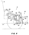
- FIGS. 6 and 7 shown embodiment of the pivot cylinder 34a outside of the insert 20 and arranged above the telescopic arm 16 and grips the vehicle body 12 or 14 at one end and at the other end at a pivot point 36a of the carrier 22a.
- the carrier 22 can be compared to the vehicle chassis 14 lock what is explained with reference to FIG. 8.
- the Lock shown is suitable for all in the figures shown variants.
- the purpose of locking For example, two catch hooks 40 open at the top serve, each offset to the side of the vehicle's longitudinal axis one of the two axis funnels 42 are rigidly attached. At spring-loaded axle, however, it is recommended that the catch hook 40 to fix the vehicle chassis 14.
- the protrusions are up open, slot-like recesses of the catch hook 40 adapted.
- the projections 38 can be received by the recesses become. They can be within the recesses of the Lock catch hook 40.
- the type of locking was not shown in more detail. Locking mechanisms are suitable, for example in the way they are used in quick couplers from Lower links are common.
- the interlock between carrier 22 and vehicle chassis 14 may alternatively be used a castle or by training corresponding Ho
- the carrier 22 carries a three-point suspension with a Upper link 44 and two lateral lower links 46, each hinged to the carrier 22 in the usual manner are.
- the lower links 46 can be associated with the Raise carrier 22 articulated lifting arms 48 and lifting struts 50 and lower.
- the lifting arms 48 are actuated in the usual manner Way by power cylinder 52, one end 53 on the carrier 22 and the other end thereof at one Articulation point 54 of the associated lifting arm 48 articulates.
- the transverse movement of the lower link 46 can be done by usual Limit stabilizing link 47.
- the free ends of the Lower link 46 can be indicated only by one Device mast 56 connected to the free end of the upper link 44 his.
- FIGS. 4 to 8 there is also a PTO shaft 60 indicated that from a PTO gear housing 62nd protrudes.
- the PTO gear housing 62 is not on one flange-mounted transmission housing of the vehicle.
- the PTO 60 is by a common PTO shield 64 covered.
- the lifting cylinder 28, the extension cylinder 30 and the Swivel cylinders 34 can act as double-acting hydraulic cylinders be trained.
- the hydraulic supply takes place via the On-board vehicle hydraulic system. Operation of the Hydraulic cylinder is carried out in the vehicle cabin arranged actuators, over which hydraulic valves operate to adjust the hydraulic oil flows accordingly adjust.
- the power jack cylinders 52 are on usual Actuated or controlled. A well-known, not Level control device shown in more detail is used for control the pivot cylinder 34 and the orientation of the carrier 22 in a desired working position.
- a towing device 70 is shown in FIGS. 9 and 10 out, which is attached to the PTO gear housing 62. It is a conventional height adjustable Towing device 70 with two lateral guide rails 72 the one that is adjustable in height and in different Guide the lockable hitch 74 at high altitudes.
- the Attachment of the hitch 70 on the stationary PTO gear housing 62 has the advantage that the Construction of the telescopic rear interface not through attaching devices is charged.
- FIGS. 11 and 12 An alternative embodiment is shown in FIGS. 11 and 12 for a hitch 76.
- the Trailer coupling 78 attached to the three-point hitch 22.
- This Training is structurally simpler than that in Figures 9 and 10, since the guide rails 72 are omitted can. The height is adjusted via the telescopic arm.
Abstract
Description
Die Erfindung betrifft ein Kraftfahrzeug für industrielle und/oder landwirtschaftliche Arbeiten, insbesondere für einen Ackerschlepper, mit einer einen Dreipunkt-Geräteanbau enthaltenden Anbauschnittstelle an der Fahrzeugrückseite oder an der Fahrzeugvorderseite. Es ist ein an dem Fahrzeugchassis angelenkter teleskopierbarer und um eine horizontale Achse in vertikaler Richtung schwenkbaren Teleskoparm vorgesehen, an dessen freiem ausfahrbaren Ende ein Träger angeordnet ist, der die Anbauschnittstelle mit dem Dreipunkt-Geräteanbau trägt.The invention relates to a motor vehicle for industrial and / or agricultural work, especially for one Agricultural tractor with a three-point implement attachment Mounting interface on the rear of the vehicle or on the Front of the vehicle. It is on the vehicle chassis articulated telescopic and about a horizontal axis in provided in the vertical direction pivotable telescopic arm the free extendable end of a carrier is arranged, the carries the mounting interface with the three-point attachment.
Insbesondere Ackerschlepper, aber auch andere industrielle oder landwirtschaftlich verwendete Arbeitsfahrzeuge dienen neben der Ausführung von Transportarbeiten vor allem als Arbeitsmaschine, durch die sich beispielsweise Arbeiten auf dem Feld ausführen lassen. Zu diesem Zweck läßt sich an das Arbeitsfahrzeug ein für die durchzuführende Arbeit geeignetes Arbeitsgerät anbauen. Der Traktor ist somit im Gegensatz zu Einzweckmaschinen ein offenes System, das erst durch die Kopplung mit einem Arbeitsgerät zu einer arbeitsfähigen Maschine wird.Agricultural tractors in particular, but also other industrial or Agricultural work vehicles are used in addition to Execution of transport work primarily as a work machine, through which, for example, work is carried out in the field to let. For this purpose, the work vehicle can be used Install suitable equipment for the work to be carried out. In contrast to single-purpose machines, the tractor is one open system, which is only possible by coupling with a working device becomes a workable machine.
Da das Kraftfahrzeug für die Durchführung unterschiedlicher Arbeiten mit unterschiedlichen Arbeitsgeräten koppelbar sein soll, kommt der Anbauschnittstelle zwischen Kraftfahrzeug und Arbeitsgerät eine besondere Bedeutung zu. Unter einer Anbauschnittstelle sind alle Einrichtungen zu verstehen, die erforderlich sind, um Arbeitsgeräte an das Kraftfahrzeug anzukoppeln und gegebenenfalls mit Antriebsenergie zu versorgen.Because the motor vehicle for carrying out different Working with different tools can be coupled the interface between the motor vehicle and Work equipment a special meaning. Under a mounting interface all facilities are required to be understood are to couple work tools to the motor vehicle and if necessary to supply them with drive energy.
Eine übliche Anbauschnittstelle, mit der heute die meisten Ackerschlepper und ähnliche landwirtschaftliche Kraftfahrzeuge versehen sind, enthält einen sogenannten Dreipunkt-Geräteanbau, wie er beispielsweise durch ISO 730 oder DIN 9674 definiert ist. Dieser weist zwei über eine Hubwelle miteinander verbundene Hubarme auf, an denen je ein zugehöriger hydraulischer Kraftheberzylinder angreift. Jeder Hubarm ist über eine Hubstange oder eine Hubspindel mit einem zugehörigen Unterlenker verbunden, der einen unteren Kopplungspunkt trägt. Desweiteren enthält der Dreipunkt-Geräteanbau einen am Schlepperrumpf angelenkten Oberlenker mit einem dritten mittigen, oberen Kopplungspunkt.A common mounting interface with which most today Agricultural tractors and similar agricultural vehicles contains a so-called three-point attachment, as defined for example by ISO 730 or DIN 9674 is. This has two connected to each other via a lifting shaft Lift arms on, each with an associated hydraulic Lift cylinder attacks. Each lifting arm is via a lifting rod or a lifting spindle with an associated lower link connected, which carries a lower coupling point. Furthermore the three-point attachment includes one on the tractor body articulated top link with a third middle, upper Coupling point.
Der Dreipunkt-Geräteanbau ermöglicht es, Arbeitsgeräte auf einfache Weise rasch an den Ackerschlepper zu montieren. Hierbei wird der Ackerschlepper an das auf dem Boden abgestellte Arbeitsgerät herangefahren. Die Koppelungspunkte werden an entsprechende Aufnahmen des Anbaugeräts gekoppelt, so daß das Arbeitsfahrzeug und das Arbeitsgerät eine funktionsfähige Prozeßeinheit bilden. Gegebenenfalls wird eine Zapfwelle des Arbeitsfahrzeugs an eine Eingangswelle des Arbeitsgeräts angeschlossen. Desweiteren können zwischen dem Arbeitsfahrzeug und dem Arbeitsgerät elektrische und hydraulische Verbindungen zur Kraft- und Signalübertragung hergestellt werden. Durch Betätigung der Kraftheberzylinder läßt sich das Arbeitsgerät anheben und in seiner Höhenlage innerhalb bestimmter Grenzen einstellen, um das Arbeitsgerät zwischen einer Transportstellung und der gewünschten Arbeitsposition zu bewegen. Das Arbeitsgerät benötigt dabei in vielen Fällen kein eigenes Fahrgestell.The three-point attachment allows tools to be attached easy to assemble quickly on the tractor. Here the tractor is attached to the one on the ground the parked implement. The coupling points are coupled to corresponding recordings of the attachment, so that the work vehicle and the implement are functional Form process unit. If necessary, a PTO of the work vehicle to an input shaft of the implement connected. Furthermore, between the work vehicle and the implement electrical and hydraulic connections for power and signal transmission. By The power tool can be operated by the power cylinder lift and its altitude within certain limits adjust the implement between a transport position and move to the desired work position. The In many cases, the implement does not need its own Chassis.
Trotz des vielseitig anwendbaren Dreipunkt-Geräteanbaus ist das Einsatzspektrum für das Kraftfahrzeug noch begrenzt.Despite the versatile three-point device attachment, that is Range of application for the motor vehicle still limited.
Durch die DE-A-33 33 865 ist ein landwirtschaftlicher Schlepper mit einer heckseitigen und einer frontseitigen Hebevorrichtung bekannt geworden. Die frontseitige Hebevorrichtung enthält einen nach unten gerichteten Profilträger, der sich mittels eines hydraulischen Steuerzylinders um einen horizontalen Querbolzen gegenüber einer fahrzeugfesten Traggabel verschwenken läßt. An der Vorderseite des Profilträgers ist das Außenrohr eines Teleskoprohres angeschweißt. In dem Außenrohr ist ein Innenrohr geführt und läßt sich durch einen hydraulischer Steuerzylinder relativ zum Außenrohr verschieben. DE-A-33 33 865 is an agricultural tractor with a rear and a front lifting device known. The front lifting device contains a downward-facing profile beam, which can be fixed by means of of a hydraulic control cylinder around a horizontal one Cross bolt compared to a vehicle-mounted fork can pivot. This is on the front of the profile beam Welded outer tube of a telescopic tube. In the outer tube is an inner tube and can be through a move the hydraulic control cylinder relative to the outer tube.
Das Innenrohr trägt an seinem unteren Ende einen halbkreisförmig gekrümmten Bügel, an dem eine mittige obere Befestigungszunge und zwei seitliche untere Befestigungszungen angebracht sind. Die Befestigungszungen bilden eine Dreipunkt-Befestigung für Maschinen und Geräte, wie beispielsweise Bodenfräsen. Die bekannte frontseitige Hebevorrichtung ist nicht für Geräte, beispielsweise für Pflüge, geeignet, durch die hohe Zugkräfte in den Schlepper eingeleitet werden.The inner tube carries one at its lower end semicircular curved temple on which a central upper Fastening tongue and two side lower fastening tongues are attached. The fastening tongues form a three-point fastening for machines and devices such as Tillage. The known front lifting device is not suitable for devices such as plows the high tractive forces are introduced into the tractor.
Die der Erfindung zugrunde liegende Aufgabe wird darin gesehen, ein gattungsgemäßes Kraftfahrzeug derart auszubilden, daß sein Einsatzspektrum erweitert wird. Insbesondere soll die Funktionalität der Anbauschnittstelle erweitert werden, um neue Einsatzbereiche für das Kraftfahrzeug zu erschließen.The object underlying the invention is seen in to train a generic motor vehicle in such a way that Range of applications is expanded. In particular, the Functionality of the mounting interface can be expanded to include new ones Open up areas of application for the motor vehicle.
Die Aufgabe wird erfindungsgemäß durch die Lehre des
Patentanspruchs 1 gelöst. Weitere vorteilhafte Ausgestaltungen
und Weiterbildungen der Erfindung gehen aus den Unteransprüchen
hervor.The object is achieved by the teaching of
Das erfindungsgemäße Kraftfahrzeug für industrielle und/oder landwirtschaftliche Arbeiten enthält eine Anbauschnittstelle an der Fahrzeugrückseite oder an der Fahrzeugvorderseite mit einem Dreipunkt-Geräteanbau, der vorzugsweise gemäß ISO 730 oder DIN 9674 ausgebildet sein kann. An dem Fahrzeugchassis, beispielsweise am Fahrzeugrumpf, einem Fahrzeugrahmen oder dem Fahrzeugaufbau, ist ein teleskopierbarer und um eine horizontale Achse in vertikaler Richtung schwenkbarer Teleskoparm angelenkt, an dessen freiem Ende ein Träger angeordnet ist, der die Anbauschnittstelle mit dem Dreipunkt-Geräteanbau trägt. Desweiteren ist eine Verriegelungsvorrichtung vorgesehen, durch die der Träger gegenüber dem Fahrzeugchassis wahlweise fixierbar ist, wenn sich der Teleskoparm beispielsweise in einer eingefahrenen und abgesenkten Arbeitsstellung befindet.The motor vehicle according to the invention for industrial and / or agricultural work includes an attachment interface on the back of the vehicle or on the front of the vehicle with a Three-point attachment, preferably in accordance with ISO 730 or DIN 9674 can be formed. On the vehicle chassis, for example on the vehicle fuselage, a vehicle frame or the vehicle body, is a telescopic and about a horizontal axis Articulated telescopic arm hinged in the vertical direction the free end of which is arranged a carrier which Interface with the three-point device attachment. Furthermore, a locking device is provided by which the carrier can choose from compared to the vehicle chassis is fixable if the telescopic arm, for example, in a retracted and lowered working position.
Durch die erfindungsgemäße teleskopierbare Anbauschnittstelle werden für das Kraftfahrzeug, insbesondere den Ackerschlepper, neue Einsatzbereiche erschlossen. Sie ermöglicht einerseits die Durchführung aller Arbeiten, die mit einem herkömmlichen Dreipunkt-Geräteanbau erledigt werden konnten. Andererseits ist eine große Ladehöhe an der Fahrzeugrückseite bzw. an der Fahrzeugvorderseite ständig verfügbar. Das erfindungsgemäße Kraftfahrzeug ermöglicht das Bewegen von Arbeitsgeräten mit erweiterten Freiheitsgraden und erweitertem Hubbereich. Es läßt sich einerseits als konventionellen Schlepper mit konventioneller Anbauschnittstelle und andererseits als funktionsfähiger Lader einsetzen. Ein bevorzugter Anwendungsfall ist darin zu sehen, daß ein normaler Arbeitsbetrieb (Pflügen) erfolgen kann und daß sich das Arbeitsgerät (Pflug) so weit ausheben läßt, daß seine Ablage auf einem Anhänger oder einer erhöhten Ablage ohne zusätzliche Hilfsmittel möglich ist. Durch das einfache, rasch auszuführende Verladen kann ein rascher Wechsel zwischen räumlich getrennten Arbeitseinsatzorten erfolgen, indem nach einem Arbeitseinsatz das Arbeitsgerät auf einen Anhänger verladen, der Anhänger an das Kraftfahrzeug angehängt und zu einem neuen Einsatzort bei hoher Fahrgeschwindigkeit gefahren wird. Es ist ein Anheben von Geräten bis beispielsweise in Höhe der Kabinenoberkante möglich, so daß die Geräte hoch angehoben und beispielsweise auf Regalen oder auf Anhängern abgelegt werden können, ohne sie zuvor vom Dreipunkt-Geräteanbau zu lösen.Through the telescopic mounting interface according to the invention are used for the motor vehicle, especially the agricultural tractor, opened up new areas of application. On the one hand, it enables Carrying out all work with a conventional Three-point device installation could be done. On the other hand a large loading height on the rear of the vehicle or on the Vehicle front always available. The invention Motor vehicle enables the movement of work equipment extended degrees of freedom and extended stroke range. It leaves on the one hand as a conventional tractor with conventional Interface and on the other hand as a functional Insert the loader. A preferred application is to be seen in the fact that normal work (plowing) can be done and that the implement (plow) so far can dig out that its storage on a trailer or a elevated storage is possible without additional aids. By simple, quick loading can be quicker Change between spatially separated work locations, by putting the implement on one after a job Load trailer, the trailer attached to the motor vehicle and to a new location with high driving speed is driven. It is lifting equipment up for example possible at the top of the cabin, so that the devices raised high and on shelves or on Trailers can be stored without first having to attach the three-point device to solve.
Ein weiterer Vorteil der teleskopierbaren Anbauschnittstelle liegt darin, daß das Koppeln von Anbaugeräten und beispielsweise auch das Graben mit der Erdschaufel durch horizontale Bewegungen des Teleskoparms realisiert werden können, ohne daß der Traktor bewegt werden muß.Another advantage of the telescopic mounting interface is that the coupling of attachments and, for example digging with a shovel through horizontal Movements of the telescopic arm can be realized without the tractor must be moved.
Durch die erfindungsgemäße Verriegelungsvorrichtung läßt sich der Träger, wenn er sich in einer Arbeitsstellung befindet, mit dem Fahrzeugchassis starr verbinden und verriegeln. Bei Transportarbeiten oder bei Arbeiten mit Dreipunktanbau werden damit die auftretenden Lasten von dem Träger aus direkt über die Verriegelungseinrichtung in das Fahrzeugchassis eingeleitet, so daß der Teleskoparm entlastet ist.The locking device according to the invention allows the carrier, when in a working position, with rigidly connect and lock the vehicle chassis. At Transport work or when working with three-point attachment thus the occurring loads directly from the carrier the locking device in the vehicle chassis initiated so that the telescopic arm is relieved.
Die Anbauschnittstelle enthält vorzugsweise neben dem Dreipunkt-Geräteanbau weitere am Träger befestigbare Anbauvorrichtungen und/oder Anhängevorrichtungen. Es lassen sich so die Funktionen der heute üblichen Einpunktanhänge-Vorrichtungen, wie Zughaken, starres Zugpendel, Anhängekupplung und dergleichen nachbilden. Bei allen Ausbildungen können Zugösen eines anzuhängenden Gerätes vom Boden aufgenommen und hydraulisch in Betriebsposition gebracht werden.The mounting interface preferably contains in addition to the Three-point device attachment further attachment devices that can be attached to the carrier and / or hitching devices. It can be so Functions of today's single-point hitching devices, such as tow hook, rigid drawbar, trailer coupling and simulate the like. With all training courses, towing eyes can be used of a device to be attached to the floor and be brought into operating position hydraulically.
Vorzugsweise ist der Teleskoparm hinsichtlich der Quererstreckung des Fahrzeugs mittig, hinter der Fahrerplattform, insbesondere hinter der Kabine, und vor der Hinterachse angebaut, wobei sich eine teleskopierbare Heckschnittstelle ergibt. Das Kraftfahrzeug kann dabei in vorteilhafter Weise als Mittel- oder Frontsitzschlepper ausgebildet sein.The telescopic arm is preferably with respect to the transverse extent of the vehicle in the middle, behind the driver platform, especially behind the cabin, and in front of the rear axle attached, with a telescopic rear interface results. The motor vehicle can advantageously as Middle or front seat tractor be formed.
Gemäß einer bevorzugten Ausgestaltung der erfindungsgemäßen Geräteschnittstelle enthält der Teleskoparm im wesentlichen ein äußeres am Fahrzeugchassis schwenkbar angelenktes Schwenkteil und mindestens einen ausfahrbaren Einschub, der der Längenausdehnung dient. Am freien Ende des Einschubs ist der Träger befestigt, der einen Dreipunkt-Geräteanbau trägt.According to a preferred embodiment of the invention The telescopic arm essentially contains a device interface outer swivel part hinged to the vehicle chassis and at least one retractable slot that the Linear expansion serves. At the free end of the slot is the Carrier attached, which carries a three-point attachment.
Einer besonders einfachen Ausbildung der Erfindung zur Folge, enthält der Teleskoparm zwei konzentrisch ineinanderschiebbare Schüsse. Diese können Rechteckprofile aufweisen, die ein vergleichsweise hohes Widerstandsmoment bieten und eine einfache Konstruktion der Gleitführungen und der Stützpunkte für Hubeinrichtungen ermöglichen. Für besondere Anwendungsfälle kann auch die Verwendung eines Teleskoparms mit wenigstens drei konzentrisch ineinanderschiebbaren Schüssen vorteilhaft sein.According to a particularly simple embodiment of the invention, the telescopic arm contains two concentric telescopes Shots. These can have rectangular profiles, the one offer a comparatively high section modulus and a simple construction of the slide guides and the support points enable for lifting devices. For special applications can also use a telescopic arm with at least three concentrically nested shots can be advantageous.
Die Schwenk- und Ausfahrbewegung des Teleskoparms und gegebenenfalls die Relativbewegung des Trägers gegenüber dem Teleskoparm erfolgt gemäß bevorzugter Weiterbildungen der Erfindung durch Druckmittelkolben-Zylindereinheiten, zweckmäßigerweise durch doppelwirkende Hydraulikzylinder. Diese können durch das Hydrauliksystem des Kraftfahrzeugs mit Hydraulikdruckflüssigkeit versorgt werden. Insbesondere kann zum Aus- und Einfahren der Schüsse wenigstens ein Ausschubzylinder zwischen dem Schwenkteil und einem ausfahrbaren Einschub bzw. jeweils zwischen den Schüssen des Teleskoparms vorgesehen sein. Vorzugsweise greifen zwei wirkungsmäßig parallel angeordnete Hubzylinder einerseits an dem Fahrzeugchassis und andererseits an dem Teleskoparm an, um das Anbaugerät vertikal zu bewegen.The swiveling and extending movement of the telescopic arm and optionally the relative movement of the carrier relative to the Telescopic arm takes place according to preferred further developments of the Invention by pressure medium piston-cylinder units, expediently thanks to double-acting hydraulic cylinders. This can with the hydraulic system of the motor vehicle Hydraulic hydraulic fluid are supplied. In particular, can at least one extension cylinder for extending and retracting the shots between the swivel part and an extendable Insert or between the shots of the telescopic arm be provided. Preferably two are effective parallel lifting cylinders on the one hand on the vehicle chassis and on the other hand on the telescopic arm to the To move the attachment vertically.
Um den Träger in eine gewünschte definierte Ausrichtung zu bringen oder in einer definierten Lage halten zu können, ist es von Vorteil den Träger mit dem freien Ende des Teleskoparms, beispielsweise mit dem freien Ende eines ausfahrbaren Einschubs, gelenkig zu verbinden. Zwischen dem Teleskoparm bzw. dem Fahrzeugaufbau einerseits und dem beweglichen Träger andererseits ist wenigstens ein doppelwirkender Schwenkzylinder angeordnet, durch den sich der Träger verschwenken und ausrichten läßt.To the carrier in a desired defined orientation bring or keep in a defined position, it is advantageous the carrier with the free end of the telescopic arm, for example with the free end of an extendable Insert, articulated to connect. Between the telescopic arm or the vehicle body on the one hand and the movable carrier on the other hand there is at least one double-acting swivel cylinder arranged through which the carrier pivot and aligns.
Bei einer Reihe von Arbeiten soll das Arbeitsgerät eine gewünschte Ausrichtung zum Boden beibehalten, auch wenn der Teleskoparm bewegt wird. Hierfür ist es von besonderem Vorteil wenn das Schwenksystem so ausgebildet ist, daß die Kopplungsebene unabhängig von der Neigung des Teleskoparms senkrecht oder in einer anderen gewünschten Lage gehalten wird. Eine bevorzugte Weiterbildung der Erfindung sieht hierfür eine Niveausteuereinrichtung vor, die den wenigstens einen Schwenkzylinder derart ansteuert, daß das Gerät unabhängig von der Schwenklage des Teleskoparms in einer gewünschten Ausrichtung relativ zum Boden gehalten wird. Zur Ermittlung eines Istwertsignals für die Niveausteuerung kann die Ausrichtung der gewünschten Lage des Geräts durch einen geeigneten Sensor überwacht werden. The implement should perform a series of tasks maintain the desired orientation to the ground, even if the Telescopic arm is moved. It is particularly advantageous for this if the swivel system is designed so that the coupling plane regardless of the inclination of the telescopic arm vertically or held in any other desired position. A preferred development of the invention provides for this Level control device before the at least one Controls the pivot cylinder so that the device is independent of the swivel position of the telescopic arm in a desired Alignment is held relative to the ground. For investigation an actual value signal for level control can Alignment of the desired position of the device with a suitable sensor are monitored.
Es hat sich auch als vorteilhaft herausgestellt, einen an den Dreipunkt-Geräteanbau befestigbaren Adapter vorzusehen, der der Aufnahme von speziellen Geräten dient, deren Anbauschnittstelle beispielsweise nicht durch die oben genannte Norm für einen Dreipunkt-Geräteanbau definiert ist. Durch diese Kombination kann ein konventioneller Frontlader ersetzt werden. Diese Ausbildung ermöglicht beispielsweise die Durchführung aller Arbeiten, die bisher mit einem Frontlader erledigt wurden, sofern die Frontladerwerkzeuge (Erdschaufel, Staplergabel usw.) mittels Spezialadapter an den Dreipunkt-Geräteanbau befestigt werden.It has also proven to be advantageous to send one to the To provide three-point attachment attachable adapter that the Includes special devices, their mounting interface for example not by the above norm for one Three-point device attachment is defined. With this combination a conventional front loader can be replaced. This Training, for example, enables everyone to be carried out Work that was previously done with a front loader if the front loader tools (earth bucket, fork, etc.) attached to the three-point device attachment using a special adapter become.
Anhand der Zeichnung, die Ausführungsbeispiele der Erfindung zeigt, werden nachfolgend die Erfindung sowie weitere Vorteile und vorteilhafte Weiterbildungen und Ausgestaltungen der Erfindung näher beschrieben und erläutert.Based on the drawing, the embodiments of the invention shows, the invention and further advantages are below and advantageous developments and refinements of Invention described and explained in more detail.
Es zeigt:
- Fig. 1
- die schematische Perspektivansicht eines erfindungsgemäßen Kraftfahrzeugs mit teleskopierbarer Heckschnittstelle in Arbeitsstellung,
- Fig. 2
- ein Kraftfahrzeug gemäß Fig. 1 mit abgesenkter Heckschnittstelle,
- Fig. 3
- ein Kraftfahrzeug gemäß Fig. 1 mit angehobener Heckschnittstelle,
- Fig. 4
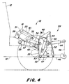
- die schematische Seitenansicht des hinteren Bereichs eines Kraftfahrzeugs mit teleskopierbarer Heckschnittstelle bei abgesenkter Position des Teleskoparms, dessen Träger durch einen inneren Schwenkzylinder verschwenkbar ist,
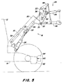
- Fig. 5
- eine der Fig. 4 entsprechende Seitenansicht, in der der Teleskoparm seine höchste Position einnimmt,
- Fig. 6
- die schematische Seitenansicht des hinteren Bereichs eines Kraftfahrzeugs mit teleskopierbarer Heckschnittstelle bei abgesenkter Position des Teleskoparms, dessen Träger durch einen äußeren Schwenkzylinder verschwenkbar ist,
- Fig. 7
- eine der Fig. 6 entsprechende Seitenansicht, in der der Teleskoparm seine höchste Position einnimmt,
- Fig. 8
- die schematische Seitenansicht des hinteren Bereichs eines Kraftfahrzeugs mit teleskopierbarer Heckschnittstelle und Arretiervorrichtung für den Dreipunktanbau,
- Fig. 9
- die schematische Seitenansicht des hinteren Bereichs eines Kraftfahrzeugs mit teleskopierbarer Heckschnittstelle und am Fahrzeugrumpf montierter Anhängevorrichtung,
- Fig. 10
- die Anhängevorrichtung der Fig. 9 von hinten gesehen,
- Fig. 11
- die schematische Seitenansicht des hinteren Bereichs eines Kraftfahrzeugs mit teleskopierbarer Heckschnittstelle und am Dreipunktanbauträger montierter Anhängevorrichtung und
- Fig. 12
- die Anhängevorrichtung der Fig. 11 von hinten gesehen.
- Fig. 1
- the schematic perspective view of a motor vehicle according to the invention with telescopic rear interface in the working position,
- Fig. 2
- 1 with the rear interface lowered,
- Fig. 3
- 1 with raised rear interface,
- Fig. 4
- the schematic side view of the rear area of a motor vehicle with telescopic rear interface when the telescopic arm is in the lowered position, the support of which can be pivoted by an inner pivot cylinder,
- Fig. 5
- 4 shows a side view corresponding to FIG. 4, in which the telescopic arm assumes its highest position,
- Fig. 6
- the schematic side view of the rear area of a motor vehicle with telescopic rear interface when the telescopic arm is in the lowered position, the support of which can be pivoted by an outer pivot cylinder,
- Fig. 7
- 6 shows a side view corresponding to FIG. 6, in which the telescopic arm assumes its highest position,
- Fig. 8
- the schematic side view of the rear area of a motor vehicle with telescopic rear interface and locking device for three-point attachment,
- Fig. 9
- the schematic side view of the rear area of a motor vehicle with a telescopic rear interface and a hitch mounted on the vehicle body,
- Fig. 10
- 9 seen from behind,
- Fig. 11
- the schematic side view of the rear area of a motor vehicle with telescopic rear interface and mounted on the three-point hitch and
- Fig. 12
- the hitch of Fig. 11 seen from behind.
Bei dem in den Figuren 1 bis 3 dargestellten Kraftfahrzeug handelt es sich beispielsweise um einen Mittelsitzschlepper, der nach Art eines heutigen Fast- oder MBtrac ausgebildet ist.In the motor vehicle shown in Figures 1 to 3 it is, for example, a center seat tractor, which is designed in the manner of today's Fast- or MBtrac.
Hinter der Fahrzeugkabine 12 und mittig bezüglich der
Quererstreckung des Fahrzeugs ist am Fahrzeugchassis 14 ein
Teleskoparm 16 angelenkt, der einen Schwenkteil 18 und einen
ausfahrbaren Einschub 20 aufweist. An dem freien Ende des
Ausschubs 20 ist ein Träger 22 angelenkt, auf dem ein
Dreipunkt-Geräteanbau 24 und weitere in den Figuren 1 bis 3
nicht näher dargestellte Anbauvorrichtungen montiert sind,
deren Anbauschnittstellen vorzugsweise den genormten
Bestimmungen entsprechen. Weitere Anbauvorrichtungen können
auch unmittelbar am Fahrzeugchassis montiert sein.Behind the
Die Anbauschnittstelle läßt sich in zwei Betriebsmodi, dem Arbetis- oder Zugmodus und dem Hubmodus, betreiben:The mounting interface can be divided into two operating modes, the Operate Arbetis or train mode and the lift mode:
Für den Arbeitsmodus zeigt Fig. 1 den Teleskoparm 16 in
eingezogener und verriegelter Stellung. Diese Stellung ist die
Transportstellung sowie die Arbeitsstellung für alle Arbeiten
mit Dreipunktanbau. Der Träger 22 ist mit dem Fahrzeugchassis
14 starr verbunden und verriegelt. Alle Lasten werden von dem
Träger 22 aus direkt über die Verriegelung in das
Fahrzeugchassis 14 eingeleitet, so daß der Teleskoparm 16
entlastet ist. In dieser Stellung lassen sich eine in den
Figuren 1 bis 3 nicht gezeigte Zapfwelle des Arbeitsfahrzeugs
an eine Eingangswelle des Arbeitsgeräts anschließen sowie
elektrische und/oder hydraulische Verbindungen zur Kraft- und
Signalübertragung zwischen Arbeitsfahrzeug und Arbeitsgerät
herstellen. Der Arbeitsmodus wird nach dem Ankoppeln des
Gerätes durch Betätigung der Verriegelung aktiviert. Der
Arbeitsmodus entspricht dem eines herkömmlichen Dreipunktanbaus.1 shows the
Der Hubmodus geht aus den Figuren 2 und 3 hervor, in dem der
unverriegelte Träger über Hubzylinder geschwenkt und über
Ausschubzylinder ausgefahren werden kann. Fig. 2 zeigt den
Teleskoparm 16 in ausgefahrener und abgesenkter, unverriegelter
Stellung. Diese Stellung ist geeignet, um Geräte aufzunehmen.
Beispielsweise kann in dieser Stellung die Zugöse eines Geräts
oder Anhängers vom Boden aufgenommen werden. Damit lassen sich
die Funktionen Anhängekupplung und Pick-Up Hitch nachbilden. Je
nach Ausbildung des Teleskoparms können auch die Funktionen
starres Zugpendel (durch teilweises Ausschieben) und höhenverstellbare
Anhängekupplung (durch Anheben/Absenken) nachgebildet
werden.The lifting mode is shown in Figures 2 and 3, in which the
unlocked beams swiveled over lifting cylinders and over
Extension cylinder can be extended. Fig. 2 shows the
Fig. 3 zeigt den Teleskoparm in angehobener und weit ausgefahrener Stellung. Es handelt sich um den Hubmodus zum Durchführen von Hub- und Laderarbeiten oder für das Aufnehmen und Absetzen von hoch abgelegten Arbeitsgräten. Mit diesem Modus lassen sich z. B. Anbaugeräte auf Anhängern aufladen und abladen.Fig. 3 shows the telescopic arm in a raised and wide extended position. It is the lifting mode for Carrying out lifting and loading work or for picking up and dropping high-lying work bones. With this Mode can be z. B. Charge attachments on trailers and unload.
Einzelheiten der teleskopierbaren Heckschnittstelle gehen aus
den Figuren 4 bis 12 hervor. Der in diesen Figuren dargestellte
Teleskoparm 16 besteht im wesentlichen aus zwei konzentrisch
ineinanderschiebbaren Schüssen mit einem Rechteckprofil. Ein
als Schwenkteil 18 ausgebildeter Schuß ist durch eine
chassisfeste Anlenkstelle 26 derart am Fahrzeug angelenkt, daß
er sich um eine horizontale Achse in vertikaler Richtung
verschwenken läßt. Das Verschwenken erfolgt durch zwei
beidseits des Schwenkteils 18 angeordnete Hubzylinder 28, die
jeweils einenends am Fahrzeugchassis 14 und andernends an der
Mantelfläche des Schwenkteils 18 angreifen. Es versteht sich,
daß für die Ausbildung des Teleskoparms anstelle der beiden
Schüsse auch drei, vorzugsweise teleskopartig konzentrisch
ineinanderschiebbare Schüsse verwendet werden können.Details of the telescopic rear interface go out
Figures 4 to 12 emerge. The one shown in these figures
Innerhalb des Schwenkteils 18 ist ein als Einschub 20
ausgebildeter Schuß angeordnet, der sich durch einen Ausschubzylinder
30 innerhalb des Schwenkteils 18 in axialer Richtung
ein- und ausfahren läßt. Zu diesem Zweck ist ein Ende 31 des
Ausschubzylinders 30 an dem Schwenkteil 18 und sein anderes
Ende 33 an dem Einschub 20 befestigt. Der Ausschubzylinder 30
läßt sich raumsparend innerhalb des Einschubs 20 anordnen.Within the
Das aus dem Schwenkteil 18 herausragende freie Ende des
Einschubs 20 trägt ein in Fig. 5 erkennbares nach unten
abgewinkeltes Bauteil 35, welches eine Anlenkstelle 32
aufweist. Über diese Anlenkstelle 32 ist an dem Einschub 20 ein
Träger 22 verschwenkbar befestigt. Zum Verschwenken des Trägers
22 um die horizontal ausgerichtete Anlenkstelle 32 dient ein
Schwenkzylinder 34.The protruding from the
Gemäß den Figuren 4 und 5 verläuft der Schwenkzylinder 34 im
wesentlichen im Inneren des Einschubs 20 und ist mit seinem
einen Ende 37 an dem Einschub 20 und mit seinem anderen Ende an
einer Anlenkstelle 36 des Trägers 22 gelenkig befestigt. Im
Unterschied hierzu ist in der in den Figuren 6 und 7
dargestellten Ausgestaltung der Schwenkzylinder 34a außerhalb
des Einschubs 20 und oberhalb des Teleskoparms 16 angeordnet
und greift einenends an dem Fahrzeugaufbau 12 oder 14 und
anderenends an einer Anlenkstelle 36a des Trägers 22a an.According to FIGS. 4 and 5, the
Durch Betätigung des Schwenkzylinders 34, 34a läßt sich der
Träger 22, 22a um die horizontal verlaufende Anlenkstelle 32 in
und gegen den Uhrzeigersinn aus seiner in den Figuren 4 und 6
dargestellten verriegelten Arbeitsstellung verschwenken.By actuating the
Der Träger 22 läßt sich gegenüber dem Fahrzeugchassis 14
verriegeln, was anhand der Fig. 8 erläutert wird. Die
dargestellte Verriegelung eignet sich für alle in den Figuren
dargestellten Ausführungsvarianten. Dem Zweck der Verriegelung
können beispielsweise zwei nach oben offene Fanghaken 40
dienen, die seitlich versetzt zur Fahrzeuglängsachse je an
einem der beiden Achstrichter 42 starr befestigt sind. Bei
gefederter Achse empfiehlt es sich jedoch, die Fanghaken 40 an
dem Fahrzeugchassis 14 zu befestigen. An dem Träger 22 sind
zwei sich quer zur Fahrzeuglängsrichtung erstreckende
Vorsprünge 38 angebracht. An die Vorsprünge sind nach oben
offene, schlitzartige Ausnehmungen der Fanghaken 40 angepaßt.
Die Vorsprünge 38 können von den Ausnehmungen aufgenommen
werden. Sie lassen sich innerhalb der Ausnehmungen der
Fanghaken 40 verriegeln. Die Art der Verriegelung wurde nicht
näher dargestellt. Es eignen sich beispielsweise Verriegelungsmechanismen
in der Art, wie sie bei Schnellkupplern von
Unterlenkern üblich sind. Die Verriegelung zwischen Träger 22
und Fahrzeugchassis 14 kann alternativ auch durch Verwendung
eines Schlosses oder durch die Ausbildung korrespondierender
Bohrungen und Absteckbolzen erfolgen.The
Durch die Verriegelung zwischen Träger 22 und Fahrzeugchassis
14 kann sichergestellt werden, daß bei Transportfahrten oder
bei Arbeiten mit einem Arbeitsgerät der Träger 22, und mit ihm
die Anbauschnittstelle, gegenüber dem Fahrzeugchassis fixiert
ist und sich nicht relativ zu diesem bewegt. Dies ist besonders
bei Zapfwellenarbeiten vorteilhaft.By locking between the
Bei Verriegelung werden die von dem Träger 22 übertragenen
Kräfte unmittelbar, das heißt ohne Zwischenschaltung des
Teleskoparms 16, in die Hinterachse oder in das Fahrzeugchassis
14 eingeleitet. Damit werden insbesondere bei Zug- und
Transportarbeiten die Zugspannungen unmittelbar an das
Fahrzeugchassis übertragen, so daß der Teleskoparm bei diesen
Betriebsarten entlastet wird und daher auf relativ geringe
Belastungen ausgelegt werden kann.When locked, the transmitted from the
Der Träger 22 trägt eine Dreipunkt -Aufhängung mit einem
Oberlenker 44 und zwei seitlichen Unterlenkern 46, die jeweils
an dem Träger 22 in üblicher Weise verschwenkbar angelenkt
sind. Die Unterlenker 46 lassen sich durch zugehörige, an dem
Träger 22 angelenkte Hubarme 48 und Hubstreben 50 anheben und
absenken. Die Betätigung der Hubarme 48 erfolgt auf übliche
Weise durch Kraftheberzylinder 52, deren jeweils eines Ende 53
an dem Träger 22 und deren jeweils anderes Ende an einer
Anlenkstelle 54 des zugehörigen Hubarms 48 gelenkig angreift.
Die Querbewegung der Unterlenker 46 läßt sich durch übliche
Stabilisierungslenker 47 begrenzen. Die freien Enden der
Unterlenker 46 können durch einen lediglich angedeuteten
Gerätemast 56 mit dem freien Ende des Oberlenkers 44 verbunden
sein. The
In den Figuren 4 bis 8 ist desweiteren eine Zapfwelle 60
angedeutet, die aus einem Zapfwellengetriebegehäuse 62
herausragt. Das Zapfwellengetriebegehäuse 62 ist an einem nicht
näher dargestellten Getriebegehäuse des Fahrzeugs angeflanscht.
Die Zapfwelle 60 ist durch ein übliches Zapfwellenschutzschild
64 abgedeckt.In FIGS. 4 to 8 there is also a
Die Hubzylinder 28, der Ausschubzylinder 30 und der
Schwenkzylinder 34 können als doppelwirkende Hydraulikzylinder
ausgebildet sein. Die Hydraulikversorgung erfolgt über das
bordeigene Fahrzeughydrauliksystem. Die Bedienung der
Hydraulikzylinder erfolgt durch in der Fahrzeugkabine
angeordnete Stellorgane, über die sich Hydraulikventile
betätigen lassen, um die Hydraulikölströme entsprechend
einzustellen. Die Kraftheberzylinder 52 werden auf übliche
Weise betätigt bzw. gesteuert. Eine an sich bekannte, nicht
näher dargestellte Niveauregeleinrichtung dient der Ansteuerung
des Schwenkzylinders 34 und der Ausrichtung des Trägers 22 in
eine gewünschte Arbeitsstellung.The lifting
Aus den Figuren 9 und 10 geht eine Anhängevorrichtung 70
hervor, die an dem Zapfwellengetriebegehäuse 62 befestigt ist.
Es handelt sich um eine konventionelle höhenverstellbare
Anhängevorrichtung 70 mit zwei seitlichen Führungsschienen 72
die eine in der Höhe verschiebbare und in verschiedenen
Höhenlagen arretierbare Anhängekupplung 74 führen. Die
Befestigung der Anhängevorrichtung 70 am stationären
Zapfwellengetriebegehäuse 62 hat den Vorteil, daß die
Konstruktion der teleskopierbaren Heckschnittstelle nicht durch
das Anhängen von Geräten belastet wird.A towing
Aus den Figuren 11 und 12 geht eine alternative Ausgestaltung
für eine Anhängevorrichtung 76 hervor. Hier ist die
Anhängekupplung 78 am Dreipunktanbauträger 22 befestigt. Diese
Ausbildung ist konstruktiv einfacher als die in den Figuren 9
und 10 dargestellte, da die Führungsschienen 72 entfallen
können. Die Höhenverstellung erfolgt über den Teleskoparm. An alternative embodiment is shown in FIGS. 11 and 12
for a
Auch wenn die Erfindung lediglich anhand einiger Ausführungsbeispiele beschrieben wurde, erschließen sich für den Fachmann im Lichte der vorstehenden Beschreibung sowie der Zeichnung viele verschiedenartige Alternativen, Modifikationen und Varianten, die unter die vorliegende Erfindung fallen.Even if the invention is based only on a few Exemplary embodiments have been described, open up for the expert in the light of the above description and the Drawing many different alternatives, modifications and variants which fall under the present invention.
Claims (11)
Applications Claiming Priority (2)
| Application Number | Priority Date | Filing Date | Title |
|---|---|---|---|
| DE19857167 | 1998-12-11 | ||
| DE19857167A DE19857167A1 (en) | 1998-12-11 | 1998-12-11 | Telescopic device attachment of a motor vehicle |
Publications (2)
| Publication Number | Publication Date |
|---|---|
| EP1008284A2 true EP1008284A2 (en) | 2000-06-14 |
| EP1008284A3 EP1008284A3 (en) | 2001-01-10 |
Family
ID=7890723
Family Applications (1)
| Application Number | Title | Priority Date | Filing Date |
|---|---|---|---|
| EP99124372A Withdrawn EP1008284A3 (en) | 1998-12-11 | 1999-12-07 | Telescoping implement connection for motorized vehicle |
Country Status (6)
| Country | Link |
|---|---|
| US (1) | US6764270B1 (en) |
| EP (1) | EP1008284A3 (en) |
| AR (1) | AR021586A1 (en) |
| BR (1) | BR9905837A (en) |
| CA (1) | CA2291390C (en) |
| DE (1) | DE19857167A1 (en) |
Cited By (6)
| Publication number | Priority date | Publication date | Assignee | Title |
|---|---|---|---|---|
| EP1319329A1 (en) * | 2001-12-14 | 2003-06-18 | Hermannus S.F. Reuver | Automotive agricultural working machine |
| EP2072454A3 (en) * | 2007-12-21 | 2009-10-07 | Still Sas | Industrial truck with a lifting device and a trailer device |
| EP2351476A1 (en) * | 2009-10-30 | 2011-08-03 | Sebastian Zunhammer | Three-point suspension and trailer with same |
| US8528700B2 (en) | 2007-12-21 | 2013-09-10 | Still Sas | Industrial truck with a lifting device and a towing device |
| CN104472042A (en) * | 2014-11-25 | 2015-04-01 | 上海长语信息科技有限公司 | Hillside rail base robot system |
| EP3854192A1 (en) * | 2016-02-18 | 2021-07-28 | Seedmaster Manufacturing Ltd. | Implement operating apparatus |
Families Citing this family (12)
| Publication number | Priority date | Publication date | Assignee | Title |
|---|---|---|---|---|
| DE102004051642A1 (en) * | 2004-10-23 | 2006-07-20 | Dtu Deutsche Traktoren Union Gmbh | Coupling and lifting device for tractors, in particular tractors |
| US7461702B2 (en) * | 2005-06-30 | 2008-12-09 | Farnsworth Fred L | Coupling assembly for a three point hitch assembly |
| FR2895211B1 (en) * | 2005-12-22 | 2009-11-20 | Kuhn Sa | AGRICULTURAL ENGINE COMPRISING AN IMPROVED COUPLING |
| US8602153B2 (en) * | 2007-08-06 | 2013-12-10 | Extendquip Llc | Extendable frame work vehicle |
| US7950171B2 (en) * | 2007-09-11 | 2011-05-31 | Harnischfeger Technologies, Inc. | Electric mining shovel saddle block assembly with adjustable wear plates |
| US11147203B2 (en) * | 2014-06-02 | 2021-10-19 | Philip Jensen | Middle mounted implement tractor |
| US10195913B2 (en) * | 2016-02-26 | 2019-02-05 | Vermeer Manufacturing Company | Two-point hitch mount systems |
| US11284553B2 (en) * | 2018-02-13 | 2022-03-29 | Agsoilworks Technology Company, Llc | Agricultural implements and means for engaging the same to a tractor |
| US20200181869A1 (en) * | 2018-12-07 | 2020-06-11 | Deere & Company | Boom Lock |
| US11805735B2 (en) * | 2019-02-11 | 2023-11-07 | Formation Ag LLC | Stalky crop harvesting system and process |
| CN113207343A (en) * | 2021-05-07 | 2021-08-06 | 孙耀科 | Transmission device for agricultural machinery |
| US11547035B1 (en) * | 2022-05-24 | 2023-01-10 | Amos Power, Inc. | Lift assist for an electrically driven hitch on an robotic vehicle |
Citations (1)
| Publication number | Priority date | Publication date | Assignee | Title |
|---|---|---|---|---|
| DE3333865A1 (en) | 1982-09-21 | 1984-03-22 | Patent Concern N.V., Willemstad, Curacao | Agricultural tractor |
Family Cites Families (15)
| Publication number | Priority date | Publication date | Assignee | Title |
|---|---|---|---|---|
| FR1075415A (en) | 1953-02-27 | 1954-10-15 | Hannoversche Maschb Ag Vormals | Tractor, towing vehicle or the like |
| GB797804A (en) | 1954-09-09 | 1958-07-09 | W E Bray & Company Ltd | Bulk loaders |
| FR93073E (en) | 1965-05-14 | 1969-02-07 | Bobard Emile | Self-propelled gantry allowing the incorporation of tools and machines for working the soil, in order to constitute self-propelled machines. |
| US3288316A (en) * | 1965-06-03 | 1966-11-29 | William S West | Boom for loading device |
| US3305118A (en) * | 1966-01-19 | 1967-02-21 | Le Grand H Lull | Load handling carriage |
| US3937339A (en) | 1971-10-29 | 1976-02-10 | Koehring Company | Vehicle having transverse leveling means |
| US4257732A (en) * | 1979-07-20 | 1981-03-24 | Leroy Staffanson | Hay stacker |
| US4340240A (en) * | 1980-02-04 | 1982-07-20 | Anderson Ernest L | Three point hitch adaptor for a tractor |
| JPS618138Y2 (en) * | 1980-08-26 | 1986-03-13 | ||
| NL8303818A (en) * | 1983-11-07 | 1985-06-03 | Lely Nv C Van Der | TRACTOR. |
| US4822237A (en) * | 1985-11-21 | 1989-04-18 | The Gradall Company | Extended reach materials handling apparatus |
| US4746254A (en) * | 1985-12-27 | 1988-05-24 | Westendorf Mfg. Co., Inc. | Material handling attachment for a tractor having a multiple-point hitch assembly including a high-lift mechanism |
| CA2035210A1 (en) * | 1991-01-29 | 1992-07-30 | Lloyd Orser | Lift arm lock down apparatus and method |
| FR2694316A1 (en) | 1992-07-31 | 1994-02-04 | Pel Job Groupe | Loader-excavator-elevator vehicle implement - has arm at free end of shaft and tool mounted on arm |
| GB2289036A (en) | 1994-05-04 | 1995-11-08 | Caterpillar Inc | Work vehicle |
-
1998
- 1998-12-11 DE DE19857167A patent/DE19857167A1/en not_active Ceased
-
1999
- 1999-11-23 US US09/447,363 patent/US6764270B1/en not_active Expired - Fee Related
- 1999-11-30 CA CA002291390A patent/CA2291390C/en not_active Expired - Fee Related
- 1999-12-07 AR ARP990106251A patent/AR021586A1/en active IP Right Grant
- 1999-12-07 EP EP99124372A patent/EP1008284A3/en not_active Withdrawn
- 1999-12-13 BR BR9905837-5A patent/BR9905837A/en not_active IP Right Cessation
Patent Citations (1)
| Publication number | Priority date | Publication date | Assignee | Title |
|---|---|---|---|---|
| DE3333865A1 (en) | 1982-09-21 | 1984-03-22 | Patent Concern N.V., Willemstad, Curacao | Agricultural tractor |
Cited By (8)
| Publication number | Priority date | Publication date | Assignee | Title |
|---|---|---|---|---|
| EP1319329A1 (en) * | 2001-12-14 | 2003-06-18 | Hermannus S.F. Reuver | Automotive agricultural working machine |
| EP2072454A3 (en) * | 2007-12-21 | 2009-10-07 | Still Sas | Industrial truck with a lifting device and a trailer device |
| US8528700B2 (en) | 2007-12-21 | 2013-09-10 | Still Sas | Industrial truck with a lifting device and a towing device |
| EP2351476A1 (en) * | 2009-10-30 | 2011-08-03 | Sebastian Zunhammer | Three-point suspension and trailer with same |
| CN104472042A (en) * | 2014-11-25 | 2015-04-01 | 上海长语信息科技有限公司 | Hillside rail base robot system |
| EP3854192A1 (en) * | 2016-02-18 | 2021-07-28 | Seedmaster Manufacturing Ltd. | Implement operating apparatus |
| US11382253B2 (en) | 2016-02-18 | 2022-07-12 | Dot Technology Corp. | Implement operating apparatus |
| US11812678B2 (en) | 2016-02-18 | 2023-11-14 | Dot Technology Corp. | Implement operating apparatus |
Also Published As
| Publication number | Publication date |
|---|---|
| BR9905837A (en) | 2000-08-29 |
| CA2291390C (en) | 2003-06-17 |
| DE19857167A1 (en) | 2000-06-21 |
| CA2291390A1 (en) | 2000-06-11 |
| US6764270B1 (en) | 2004-07-20 |
| AR021586A1 (en) | 2002-07-24 |
| EP1008284A3 (en) | 2001-01-10 |
Similar Documents
| Publication | Publication Date | Title |
|---|---|---|
| EP1008284A2 (en) | Telescoping implement connection for motorized vehicle | |
| EP2186713B1 (en) | Ballast device and agricultural vehicle with such device | |
| DE19951840A1 (en) | Interface for coupling work equipment to a work vehicle | |
| EP1874108A1 (en) | Three-point linkage for an agricultural or industrial utility vehicle | |
| DE3439048A1 (en) | POWER LIFTER FOR A LIFTING DEVICE | |
| EP1205097B1 (en) | Self-levelling forkhead and towing device unit | |
| DE3107228C2 (en) | Connection and coupling device for a work vehicle, in particular for an agricultural tractor | |
| DE2015792C2 (en) | Agricultural vehicle to be used as an agricultural tractor | |
| EP1068780A1 (en) | Power vehicle pivotable implement connection | |
| EP1163830B1 (en) | Drawn agricultural implement | |
| EP2042410B1 (en) | Agricultural vehicle | |
| DE3218525C2 (en) | Embankment mower | |
| DE19820377C1 (en) | Work vehicle with tiltable driver platform and tilting device | |
| DE102012015556B4 (en) | Semi-trailer with a dump body | |
| DE19703127C1 (en) | Motor vehicle trailer subassembly | |
| DE3630873A1 (en) | EQUIPMENT ATTACHMENT FOR AGRICULTURAL VEHICLES | |
| EP3311640A1 (en) | Towing device for an agricultural towing vehicle, and method of operating the same | |
| DE10120733A1 (en) | Coupling system used e.g. between tractor and plough includes load sensors in linkages for controlled adjustment of their lengths and of frame inclination | |
| DE4130829C2 (en) | Towbar for tractors | |
| EP0594160A1 (en) | Machine for use in tree nurseries, gardens and the like | |
| EP0905008A2 (en) | Carrier vehicle | |
| EP2357287B1 (en) | Work vehicle with at least one attachable frame | |
| DE3644019A1 (en) | Apparatus for connecting implements to the front of motor vehicles which can be used for agriculture, especially farm tractors | |
| EP1004231B1 (en) | Three-point hitch for tractor or the like | |
| EP4101276A1 (en) | Field working attachment |
Legal Events
| Date | Code | Title | Description |
|---|---|---|---|
| PUAI | Public reference made under article 153(3) epc to a published international application that has entered the european phase |
Free format text: ORIGINAL CODE: 0009012 |
|
| AK | Designated contracting states |
Kind code of ref document: A2 Designated state(s): AT DE FI FR GB IT |
|
| AX | Request for extension of the european patent |
Free format text: AL;LT;LV;MK;RO;SI |
|
| PUAL | Search report despatched |
Free format text: ORIGINAL CODE: 0009013 |
|
| AK | Designated contracting states |
Kind code of ref document: A3 Designated state(s): AT BE CH CY DE DK ES FI FR GB GR IE IT LI LU MC NL PT SE |
|
| AX | Request for extension of the european patent |
Free format text: AL;LT;LV;MK;RO;SI |
|
| 17P | Request for examination filed |
Effective date: 20010710 |
|
| AKX | Designation fees paid |
Free format text: AT DE FI FR GB IT |
|
| GRAP | Despatch of communication of intention to grant a patent |
Free format text: ORIGINAL CODE: EPIDOSNIGR1 |
|
| STAA | Information on the status of an ep patent application or granted ep patent |
Free format text: STATUS: THE APPLICATION IS DEEMED TO BE WITHDRAWN |
|
| 18D | Application deemed to be withdrawn |
Effective date: 20080408 |