EP2186441B1 - Foot bottom support structure for bed - Google Patents
Foot bottom support structure for bed Download PDFInfo
- Publication number
- EP2186441B1 EP2186441B1 EP08873049.4A EP08873049A EP2186441B1 EP 2186441 B1 EP2186441 B1 EP 2186441B1 EP 08873049 A EP08873049 A EP 08873049A EP 2186441 B1 EP2186441 B1 EP 2186441B1
- Authority
- EP
- European Patent Office
- Prior art keywords
- support
- section
- leg section
- portions
- thigh
- Prior art date
- Legal status (The legal status is an assumption and is not a legal conclusion. Google has not performed a legal analysis and makes no representation as to the accuracy of the status listed.)
- Not-in-force
Links
Images


Classifications
-
- A—HUMAN NECESSITIES
- A61—MEDICAL OR VETERINARY SCIENCE; HYGIENE
- A61G—TRANSPORT, PERSONAL CONVEYANCES, OR ACCOMMODATION SPECIALLY ADAPTED FOR PATIENTS OR DISABLED PERSONS; OPERATING TABLES OR CHAIRS; CHAIRS FOR DENTISTRY; FUNERAL DEVICES
- A61G7/00—Beds specially adapted for nursing; Devices for lifting patients or disabled persons
-
- A—HUMAN NECESSITIES
- A61—MEDICAL OR VETERINARY SCIENCE; HYGIENE
- A61G—TRANSPORT, PERSONAL CONVEYANCES, OR ACCOMMODATION SPECIALLY ADAPTED FOR PATIENTS OR DISABLED PERSONS; OPERATING TABLES OR CHAIRS; CHAIRS FOR DENTISTRY; FUNERAL DEVICES
- A61G7/00—Beds specially adapted for nursing; Devices for lifting patients or disabled persons
- A61G7/05—Parts, details or accessories of beds
- A61G7/065—Rests specially adapted therefor
- A61G7/075—Rests specially adapted therefor for the limbs
- A61G7/0755—Rests specially adapted therefor for the limbs for the legs or feet
-
- A—HUMAN NECESSITIES
- A47—FURNITURE; DOMESTIC ARTICLES OR APPLIANCES; COFFEE MILLS; SPICE MILLS; SUCTION CLEANERS IN GENERAL
- A47C—CHAIRS; SOFAS; BEDS
- A47C20/00—Head-, foot- or like rests for beds, sofas or the like
- A47C20/04—Head-, foot- or like rests for beds, sofas or the like with adjustable inclination
- A47C20/043—Head-, foot- or like rests for beds, sofas or the like with adjustable inclination by means of peg-and-notch or pawl-and-ratchet mechanism
-
- A—HUMAN NECESSITIES
- A47—FURNITURE; DOMESTIC ARTICLES OR APPLIANCES; COFFEE MILLS; SPICE MILLS; SUCTION CLEANERS IN GENERAL
- A47C—CHAIRS; SOFAS; BEDS
- A47C20/00—Head-, foot- or like rests for beds, sofas or the like
- A47C20/08—Head-, foot- or like rests for beds, sofas or the like with means for adjusting two or more rests simultaneously
-
- A—HUMAN NECESSITIES
- A61—MEDICAL OR VETERINARY SCIENCE; HYGIENE
- A61G—TRANSPORT, PERSONAL CONVEYANCES, OR ACCOMMODATION SPECIALLY ADAPTED FOR PATIENTS OR DISABLED PERSONS; OPERATING TABLES OR CHAIRS; CHAIRS FOR DENTISTRY; FUNERAL DEVICES
- A61G7/00—Beds specially adapted for nursing; Devices for lifting patients or disabled persons
- A61G7/002—Beds specially adapted for nursing; Devices for lifting patients or disabled persons having adjustable mattress frame
- A61G7/015—Beds specially adapted for nursing; Devices for lifting patients or disabled persons having adjustable mattress frame divided into different adjustable sections, e.g. for Gatch position
Definitions
- the present invention relates to a support mechanism for the leg section of a bed.
- Presently widely used medical and household beds are designed for allowing the back bottom section and the knee bottom section (i.e. the thigh section) of each bed to be pivotally raised and lowered so that the bed user can be supported on the bed in his/her comfortable position in response to each case.
- one end of the leg bottom section i.e. the leg section
- the knee bottom section i.e. the thigh section
- a pair of support stays are pivotally rotatably connected with the underside of the other end of the leg section so that the support stays can support the leg section above the bed frame.
- a pair of support stays are pivotally rotatably connected with the underside of the other end of the leg section, and the opposite tips of the support stays are supported by a pair of support means installed on the bed frame so that the other end of the leg section can be supported above the bed frame.
- the pair of support means consist of multiple pairs of engaging recesses disposed in the longitudinal direction of the bed frame and the height of the other end of the leg section can be adjusted by fitting the opposite tips of the support stays into a pair of engaging recesses selected from the multiple pairs of engaging recesses.
- Figs. 13 to 18 typically show an example of the conventional support mechanism for the leg section.
- Symbol a indicates a bed frame, and one end of a thigh section b is supported by the bed frame a so that the thigh section b can be pivotally raised and lowered.
- Symbol c indicates a pair of boost arms pivotally rotatably supported by the bed frame a, and the boost arms c are connected with an actuator e via an action member d so that the actuator can be moved in the right/left direction in the drawings to pivotally raise and lower the thigh section b.
- One end of a leg section f is pivotally rotatably connected with the other end of the thigh section b, and a pair of support stays g are pivotally rotatably connected with the underside of the other end of the leg section f.
- the pair of support stays g are installed on the right and left sides in the transverse direction of the leg section f, and the opposite tips of the support stays g are connected with each other by a connecting rod h.
- the near end portions of the connecting rod h beyond the opposite tips of the support stays g function as support portions i, and the extreme ends beyond the near end portions are cranked to form handle portions j.
- a pair of support members o each having two engaging recesses m and n to be engaged with the support portions i in the longitudinal direction, are provided.
- US 2004/0055088 A1 discloses a support mechanism for a leg section of a bed that is pivotally rotatably connected with an end of a thigh section and that is furthermore provided with support stays at substantially an end portion thereof.
- the free ends of the stays remote from the end pivotally attached to the leg section are received in a pair of transversely-spaced longitudinally extending slots of a bed frame.
- the slots include a plurality of transversely-extending notches along the lower walls thereof for releasably receiving the transversely-extending member such that the member is manually adjustable along the slots to lift the leg section to various positions of elevation. The closer the transversely-extending member is to the foot end of the leg portion, the higher is the elevation of the leg section.
- the slots serve to limit the forward and rearward end of the travel and prevent the lifting from the notches beyond a level necessary to the change the member between the respective notches.
- the object of this invention is to solve the abovementioned problem.
- this invention proposes a support mechanism for the leg section of a bed with the features of claim 1.
- a thigh section (knee bottom section) is supported on a bed frame in such a manner that the thigh section can be pivotally raised and lowered
- one end of a leg section (leg bottom section) is pivotally rotatably connected with the other end of the thigh section
- a support stay is pivotally rotatably connected with the underside of the other end of the leg section
- a support means of supporting the support portion provided at the opposite tip of the support stay is provided on the bed frame
- the support means comprises a guide portion and an engaging portion for movably supporting the support portion of the support stay
- said guide portion can support said support portion moved in relation with the pivotal rotation of the thigh section within the entire pivotal rotation range of the thigh section
- the engaging portion is provided above or below the vacant portion adjacent to the end portion of the guide portion on which the support portion is located when the thigh
- this invention proposes the abovementioned configuration, wherein a pair of support stays, each being the support stay described above, are provided on the right and left sides in the transverse direction of the leg section, and are connected with each other by a connecting rod at the opposite tips of the support stays; and the ends of the connecting rod beyond the support stays form support portions. Furthermore, this invention proposes the abovementioned configuration, wherein the extreme ends of the support portions are bent like hooks. Moreover, this invention proposes the abovementioned configuration, wherein the support portions and the hook portions are fitted with synthetic resin caps.
- each of the guide portions has a slope face and a low step portion at the end portion thereof on which the corresponding support portion is located when the thigh section is pivotally lowered.
- each of the support means for supporting the support portions at the tips of the support stays comprises a guide portion and an engaging portion for movably supporting the corresponding support portion, and the guide portions can support said support portions moved in relation with the pivotal rotation of the thigh section within the entire pivotal rotation range of the thigh section. Therefore, in the state where the support portions are located on the guide portions, the support portions are moved on the guide portions in the longitudinal direction of the bed frame. Consequently, the support stays do not support the other end of the leg section, and this state can be maintained within the entire pivotal rotation range of the thigh section.
- the leg section is raised to let the support portions go beyond the edges of the guide portions, to be disengaged from the guide portions, and to be engaged with the engaging portions provided above or below the vacant portions adjacent to the end portions of the guide portions.
- the support portions are lowered, and the thigh section is pivotally raised from this state.
- the one end of the leg section is moved in the longitudinal direction of the bed frame, being raised along the pivotally rotating locus of the thigh section, while the other end of the leg section moves toward the thigh section. Therefore, the support stays are moved accordingly, and the support portions are engaged with the engaging portions.
- the engaging portions are provided above the vacant portions adjacent to the end portions of the guide portions, the support portions are raised to be engaged with the engaging portions.
- the support stays are pivotally lowered and the thigh section and the leg section are lowered to lie flat.
- the support portions are located on the engaging portions. Therefore, in the case where the thigh section is pivotally raised next, the other end of the leg section can be supported at a high position again in the state where the thigh section is pivotally raised.
- the extreme ends of the support portions are bent like hooks, and in this configuration, the support portions and the hook portions are fitted with synthetic resin caps, so that the support portions can be smoothly moved on the guide portions, to prevent noise occurrence.
- each of the guide portions has a slope face and a low step portion at the end portion thereof where the corresponding support portion is located when the thigh section is pivotally lowered.
- the position of the support portions can be lowered, so that the leg section can be further lowered in height.
- symbol 1 indicates a bed frame, and one end of a thigh section 2 is supported by the bed frame 1 in such a manner that the thigh section 2 can be pivotally raised and lowered.
- symbol 3 indicates a pair of boost arms pivotally rotatably supported by the bed frame 1, and the boost arms 3 are connected with an actuator 5 such as a screwed shaft actuator via an action member 4, and if the actuator 5 is moved in the right/left direction in the drawings, the thigh section 2 can be pivotally raised and lowered.
- one end of a leg section 6 is pivotally rotatably connected with the other end of the thigh section 2, and a pair of support stays 7 are pivotally rotatably connected with the underside of the other end of the leg section 6.
- the pair of support stays 7 are disposed on the right and left sides in the transverse direction of the leg section 6, and the opposite tips of the support stays 7 are connected with each other by a connecting rod 8.
- the near end portions of the connecting rod 8 beyond the opposite tips of the support stays 7 form support portions 9, and the extreme ends of the connecting rod 8 form hook portions 10.
- the support portions 9 and the hook portions 10 are fitted with synthetic resin caps, to allow smoother sliding and to prevent noise occurrence.
- the bed frame 1 is provided with a pair of support means 11 for supporting the support portions 9, and each of the support means 11 consists of a guide portion 12 and an engaging portion 13 for movably supporting the corresponding support portion 9.
- the guide portions 12 can support the support portions 9 moved in relation with the pivotal rotation of the thigh section 2 within the entire pivotal rotation range of the thigh section 2.
- the engaging portions 13 are formed below the vacant portions adjacent to the end portions of the guide portions 12 on which the support portions 9 are located when the thigh section 2 is pivotally lowered. Further, each of the engaging portions 13 has a slope face 14 inclined upward in the direction apart from the abovementioned end of the guide portion 12.
- each of the guide portions 12 has a slope face 15 and a low step portion 16 at the end portion thereof on which the corresponding support portion 9 is located when the thigh section 2 is pivotally lowered.
- the engaging portions 13 can also be provided above the vacant portions adjacent to the end portions of the guide portions 12 on which the support portions 9 are located when the thigh section 2 is pivotally lowered as described above.
- Fig. 3 shows the state where the thigh section 2 is pivotally raised while the support portions 9 are located on the guide portions 12.
- the support portions 9 are located on the guide portions 12 on the left side in the drawing, and the support stays 7 do not support the other end of the leg section 6. Therefore, the one end of the leg section 6 is raised together with the thigh section 2.
- the other end of the leg section 6 is positioned on the bed frame 1, namely, supported at a low position.
- the support portions 9 reach the slope faces 15 as shown in Fig. 5 , and then in the state where the thigh section 2 and the leg section 6 lie flat, the support portions 9 are moved further from the slope faces 15, to be located on the low step portions 16 as shown in Fig. 6 .
- the guide portions 12 can support the support portions 9 moved in relation with the pivotal rotation of the thigh section 2 within the entire pivotal rotation range of the thigh section 2, and even when the thigh section 2 reaches the lowest end in the entire pivotal rotation range, the support portions 9 are located on the guide portions 12. Therefore, in the case where the thigh section 2 is pivotally raised from this state, namely, from the state where the thigh section 2 and the leg section 6 lie flat, the one end of the leg section 6 is raised together with the thigh section 2, taking the course reverse to the course taken when the thigh section 2 is pivotally lowered, and is supported at a high position. On the other hand, the other end of the leg section 6 is supported at a low position on the bed frame 1.
- the support stays 7 are prevented from being pivotally rotated counterclockwise in the drawings beyond the state of Fig. 8 . Therefore, if the leg section 6 is pivotally lowered in this state, the support portions 9 reach the slope faces 14 formed on the right side of the engaging portions 13 as shown in Fig. 9 , and if the leg section 6 is further pivotally lowered, the support portions 9 contact the walls of the engaging portions 13 as shown in Fig. 10 , to be kept engaged with the engaging portions 13.
- the support stays 7 support the other end of the leg section 6. Therefore, in the state where the thigh section 2 is pivotally raised, the other end of the leg section 6 is supported at a high position by the support stays 7.
- the support portions 9 are positioned below the guide portions 12. Therefore, in the case where the thigh section 2 is pivotally raised next, the one end of the leg section 6 is raised together with the thigh section 2, and the other end of the leg section 6 is raised, while being supported by the support stays 7. Thus, as shown in Fig. 10 , the other end of the leg section 6 can be supported at a high position again in the state where the thigh section 2 is pivotally raised.
- the support stays 7 are prevented from being pivotally rotated counterclockwise in the drawings beyond the state of Fig. 8 , and in the configuration where the pivotal rotation is not prevented, this invention can also be applied. That is, in this case, after the leg section 6 is raised, the support stays 7 can be held by hands and pivotally rotated forward, to shift from the state of Fig. 8 to the state of Fig. 9 , for bringing the support portions 9 into the predetermined positions.
- the switching operation between the support mode in which the other end of the leg section 6 is supported at a high position in the state where the thigh section 2 is pivotally raised and the support mode in which the other end of the leg section 6 is supported at a low position in the state where the thigh section 2 is pivotally raised can be performed irrespective of the positions assumed by the thigh section 2 and the leg section 6.
- the switching operation between the support modes can be performed as appropriate by raising both the leg section 6 and the thigh section 2.
- the support mechanism for the leg section of a bed of this invention has such advantages that the leg section support mode at the time of pivotally raising the thigh section can be easily changed and set as desired in response to the physical condition of the user and that the set support mode can be maintained. Therefore, this invention applicable to medical and household beds is highly industrially applicable.
Landscapes
- Health & Medical Sciences (AREA)
- Nursing (AREA)
- General Health & Medical Sciences (AREA)
- Life Sciences & Earth Sciences (AREA)
- Animal Behavior & Ethology (AREA)
- Public Health (AREA)
- Veterinary Medicine (AREA)
- Invalid Beds And Related Equipment (AREA)
Description
- The present invention relates to a support mechanism for the leg section of a bed.
- Presently widely used medical and household beds are designed for allowing the back bottom section and the knee bottom section (i.e. the thigh section) of each bed to be pivotally raised and lowered so that the bed user can be supported on the bed in his/her comfortable position in response to each case.
- In each of the conventional beds, one end of the leg bottom section (i.e. the leg section) is pivotally rotatably connected with the knee bottom section (i.e. the thigh section), and the other end of the leg section is kept supported on the support face of the bed frame or a pair of support stays are pivotally rotatably connected with the underside of the other end of the leg section so that the support stays can support the leg section above the bed frame.
- For example, in
JP 63-125213 A - Another patient support apparatus is disclosed in
US 2004/0055088 . -
Figs. 13 to 18 typically show an example of the conventional support mechanism for the leg section. - Symbol a indicates a bed frame, and one end of a thigh section b is supported by the bed frame a so that the thigh section b can be pivotally raised and lowered. Symbol c indicates a pair of boost arms pivotally rotatably supported by the bed frame a, and the boost arms c are connected with an actuator e via an action member d so that the actuator can be moved in the right/left direction in the drawings to pivotally raise and lower the thigh section b. One end of a leg section f is pivotally rotatably connected with the other end of the thigh section b, and a pair of support stays g are pivotally rotatably connected with the underside of the other end of the leg section f.
- As shown in
Fig. 13 , the pair of support stays g are installed on the right and left sides in the transverse direction of the leg section f, and the opposite tips of the support stays g are connected with each other by a connecting rod h. The near end portions of the connecting rod h beyond the opposite tips of the support stays g function as support portions i, and the extreme ends beyond the near end portions are cranked to form handle portions j. On the other hand, on the bed frame a, a pair of support members o, each having two engaging recesses m and n to be engaged with the support portions i in the longitudinal direction, are provided. - In the above configuration, in the state where the thigh section b is pivotally raised, in the case where the support portions i are engaged with the engaging recesses m as shown in
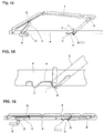
Fig. 15 , the other end of the leg section f is supported at a high position by the support stays g forming a large angle against the bed frame a. - If the thigh section b is pivotally lowered from this state, the movement of the leg section f rightward in the drawings caused by the pivotal lowering of the thigh section b can be absorbed by the pivotal rotation of the support stays g forming a large angle against the
bed frame 1, and as shown inFig. 16 , while the support portions i are engaged with the engaging recesses m, the thigh section b and the leg section f can be pivotally lowered to lie flat. Therefore, if the thigh section b is pivotally raised from this state, the other end of the leg section f is supported at a high position again as shown inFig. 14 . - On the other hand, in the state where the thigh section b is pivotally raised, in the case where the support portions i are engaged with the engaging recesses n as shown in
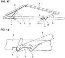
Fig. 18 , the other end of the leg section f is supported at a low position by the support stays g forming a small angle against thebed frame 1 as shown inFig. 17 . - If the thigh section b is pivotally lowered from this state, the movement of the leg section f rightward in the drawings caused by the pivotal lowering of the thigh section b cannot be absorbed by the pivotal rotation of the support stays g forming a small angle against the bed frame a. Therefore, the support portions i are gradually moved rightward in the drawings as indicated by an arrow in
Fig. 18 , and when the thigh section b and the leg section become flat, the support portions i moved from the engaging recesses n to the engaging recesses m are finally engaged with the engaging recesses m, to reach the state as shown inFig. 16 . - Therefore, if the thigh section b is next pivotally raised from this state, the state as shown in
Fig. 17 where the other end of the leg section f is supported at a low position by the support stays g forming a small angle against the bed frame a cannot be obtained, and only the state as shown inFig. 14 where the other end of the leg section f is supported at a high position can be obtained. - Further, in the state where the thigh section b and the leg section f lie flat as shown in
Fig. 16 , the support portions i cannot be moved to be engaged with the engaging recesses n, and can be moved to achieve this engagement only after the thigh section b is pivotally raised. Therefore, the operation for obtaining the bottom state as shown inFig. 17 is troublesome. -
US 2004/0055088 A1 discloses a support mechanism for a leg section of a bed that is pivotally rotatably connected with an end of a thigh section and that is furthermore provided with support stays at substantially an end portion thereof. The free ends of the stays remote from the end pivotally attached to the leg section are received in a pair of transversely-spaced longitudinally extending slots of a bed frame. The slots include a plurality of transversely-extending notches along the lower walls thereof for releasably receiving the transversely-extending member such that the member is manually adjustable along the slots to lift the leg section to various positions of elevation. The closer the transversely-extending member is to the foot end of the leg portion, the higher is the elevation of the leg section. The slots serve to limit the forward and rearward end of the travel and prevent the lifting from the notches beyond a level necessary to the change the member between the respective notches. - The object of this invention is to solve the abovementioned problem.
- To solve the abovementioned problem, this invention proposes a support mechanism for the leg section of a bed with the features of
claim 1. In this support mechanism one end of a thigh section (knee bottom section) is supported on a bed frame in such a manner that the thigh section can be pivotally raised and lowered, one end of a leg section (leg bottom section) is pivotally rotatably connected with the other end of the thigh section, a support stay is pivotally rotatably connected with the underside of the other end of the leg section, a support means of supporting the support portion provided at the opposite tip of the support stay is provided on the bed frame, the support means comprises a guide portion and an engaging portion for movably supporting the support portion of the support stay, said guide portion can support said support portion moved in relation with the pivotal rotation of the thigh section within the entire pivotal rotation range of the thigh section, and the engaging portion is provided above or below the vacant portion adjacent to the end portion of the guide portion on which the support portion is located when the thigh section is pivotally lowered. - Further, this invention proposes the abovementioned configuration, wherein a pair of support stays, each being the support stay described above, are provided on the right and left sides in the transverse direction of the leg section, and are connected with each other by a connecting rod at the opposite tips of the support stays; and the ends of the connecting rod beyond the support stays form support portions. Furthermore, this invention proposes the abovementioned configuration, wherein the extreme ends of the support portions are bent like hooks. Moreover, this invention proposes the abovementioned configuration, wherein the support portions and the hook portions are fitted with synthetic resin caps.
- Still furthermore, this invention proposes the abovementioned configuration, wherein each of the guide portions has a slope face and a low step portion at the end portion thereof on which the corresponding support portion is located when the thigh section is pivotally lowered.
- In this invention, each of the support means for supporting the support portions at the tips of the support stays comprises a guide portion and an engaging portion for movably supporting the corresponding support portion, and the guide portions can support said support portions moved in relation with the pivotal rotation of the thigh section within the entire pivotal rotation range of the thigh section. Therefore, in the state where the support portions are located on the guide portions, the support portions are moved on the guide portions in the longitudinal direction of the bed frame. Consequently, the support stays do not support the other end of the leg section, and this state can be maintained within the entire pivotal rotation range of the thigh section.
- Therefore, in the case where the thigh section is pivotally raised from the state where the thigh section and the leg section lie flat, one end of the leg section is raised along the pivotally rotating locus of the thigh section, but the other end of the leg section is supported at a low position above the bed frame while it is moved toward the thigh section in the longitudinal direction of the bed frame.
- If the thigh is pivotally lowered from this state, the other end of the leg section is moved in the direction to leave from the thigh section, and the support portions are moved on the guide portions. Thus, even if the thigh section and the leg section lie flat, the support portions are located on the guide portions.
- Therefore, if the thigh section is pivotally raised from this state, the action as described above occurs, and in the state where the thigh section is pivotally raised, the other end of the leg section can be supported again at a low position above the bed frame.
- Next, in the case where it is desired to keep the other end of the leg section at a high position when the thigh section is pivotally raised, the leg section is raised to let the support portions go beyond the edges of the guide portions, to be disengaged from the guide portions, and to be engaged with the engaging portions provided above or below the vacant portions adjacent to the end portions of the guide portions.
- In the case where the engaging portions are provided below the vacant portions adjacent to the end portions of the guide portions for example, the support portions are lowered, and the thigh section is pivotally raised from this state. As a result, the one end of the leg section is moved in the longitudinal direction of the bed frame, being raised along the pivotally rotating locus of the thigh section, while the other end of the leg section moves toward the thigh section. Therefore, the support stays are moved accordingly, and the support portions are engaged with the engaging portions. Further, in the case where the engaging portions are provided above the vacant portions adjacent to the end portions of the guide portions, the support portions are raised to be engaged with the engaging portions.
- If the thigh section is further pivotally raised from this state, the support portions engaged with the engaging portions act as fulcrums, to pivotally raise the support stays and to thereby pivotally raise the one end [NOTE: This expression, "the one end" is correct in translation, but the expression should be "the other end" in terms of the content.] of the leg section. Thus, in the state where the thigh section is pivotally raised,
the other end of the leg section is supported at a high position. - If the thigh section is pivotally lowered, in the action reverse to the abovementioned action, the support stays are pivotally lowered and the thigh section and the leg section are lowered to lie flat. In this
state, the support portions are located on the engaging portions. Therefore, in the case where the thigh section is pivotally raised next, the other end of
the leg section can be supported at a high position again in the state where the thigh section is pivotally raised. - In this invention, the extreme ends of the support portions are bent like hooks, and in this configuration, the support portions and the hook portions are fitted with synthetic resin caps, so that the support portions can be smoothly moved on the guide portions, to prevent noise occurrence.
- Further, in this invention, each of the guide portions has a slope face and a low step portion at the end portion thereof where the corresponding support portion is located when the thigh section is pivotally lowered. In this configuration, when the leg section lies flat, the position of the support portions can be lowered, so that the leg section can be further lowered in height.
-
- [
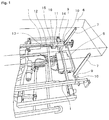
Fig. 1 ] is a typical perspective view showing an essential portion of an embodiment of this invention. - [
Fig. 2 ] is a typical side view showing an essential portion of the embodiment of this invention. - [
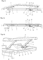
Fig. 3 ] is a typical side view showing the embodiment of this invention. - [
Fig. 4 ] is a typical side view showing an aspect different from that ofFig. 3 . - [
Fig. 5 ] is a typical side view showing an aspect further different from those of the above drawings. - [
Fig. 6 ] is a typical side view showing an aspect further different from those of the above drawings. - [
Fig. 7 ] is a typical side view showing an aspect further different from those of the above drawings. - [
Fig. 8 ] is a typical side view showing an aspect further different from those of the above drawings. - [
Fig. 9 ] is a typical side view showing an aspect further different from those of the above drawings. - [
Fig. 10 ] is a typical side view showing an aspect further different from those of the above drawings. - [
Fig. 11 ] is a typical side view showing an aspect further different from those of the above drawings. - [
Fig. 12 ] is a typical side view showing an aspect further different from those of the above drawings. - [
Fig. 13 ] is a typical perspective view showing an essential portion of a conventional support mechanism for a leg section. - [
Fig. 14 ] is a typical side view showing the action of the conventional support mechanism. - [
Fig. 15 ] is an expanded view showing an essential portion ofFig. 14 . - [
Fig. 16 ] is a typical side view showing another aspect of the action of the conventional support mechanism. - [
Fig. 17 ] is a typical side view showing a further other aspect of the action of the conventional support mechanism. - [
Fig. 18 ] is an expanded view showing an essential portion ofFig. 17 . -
- 1
- bed frame
- 2
- thigh section
- 3
- boost arm
- 4
- action member
- 5
- actuator
- 6
- leg section
- 7
- support stay
- 8
- connecting rod
- 9
- support portion
- 10
- hook portion
- 11
- support means
- 12
- guide portion
- 13
- engaging portion
- 14
- slope face
- 15
- slope face
- 16
- low step
- b
- thigh section
- c
- boost arm
- d
- action member
- e
- actuator
- f
- leg section
- g
- support stay
- h
- connecting rod
- i
- support portion
- j
- cranked handle portion
- m, n
- engaging recess
- o
- support member
- An embodiment of the support mechanism for the leg section of a bed of this invention is explained below in reference to
Figs. 1 to 12 . - In the drawings,
symbol 1 indicates a bed frame, and one end of athigh section 2 is supported by thebed frame 1 in such a manner that thethigh section 2 can be pivotally raised and lowered.Symbol 3 indicates a pair of boost arms pivotally rotatably supported by thebed frame 1, and theboost arms 3 are connected with anactuator 5 such as a screwed shaft actuator via anaction member 4, and if theactuator 5 is moved in the right/left direction in the drawings, thethigh section 2 can be pivotally raised and lowered. Further, one end of aleg section 6 is pivotally rotatably connected with the other end of thethigh section 2, and a pair of support stays 7 are pivotally rotatably connected with the underside of the other end of theleg section 6. - As shown in
Fig. 1 , the pair of support stays 7 are disposed on the right and left sides in the transverse direction of theleg section 6, and the opposite tips of the support stays 7 are connected with each other by a connectingrod 8. The near end portions of the connectingrod 8 beyond the opposite tips of the support stays 7form support portions 9, and the extreme ends of the connectingrod 8form hook portions 10. Though not shown in the drawings, thesupport portions 9 and thehook portions 10 are fitted with synthetic resin caps, to allow smoother sliding and to prevent noise occurrence. - On the other hand, the
bed frame 1 is provided with a pair of support means 11 for supporting thesupport portions 9, and each of the support means 11 consists of aguide portion 12 and an engagingportion 13 for movably supporting thecorresponding support portion 9. As can be seen from the action described later, theguide portions 12 can support thesupport portions 9 moved in relation with the pivotal rotation of thethigh section 2 within the entire pivotal rotation range of thethigh section 2. The engagingportions 13 are formed below the vacant portions adjacent to the end portions of theguide portions 12 on which thesupport portions 9 are located when thethigh section 2 is pivotally lowered. Further, each of the engagingportions 13 has aslope face 14 inclined upward in the direction apart from the abovementioned end of theguide portion 12. On the other hand, each of theguide portions 12 has aslope face 15 and alow step portion 16 at the end portion thereof on which thecorresponding support portion 9 is located when thethigh section 2 is pivotally lowered. Meanwhile, the engagingportions 13 can also be provided above the vacant portions adjacent to the end portions of theguide portions 12 on which thesupport portions 9 are located when thethigh section 2 is pivotally lowered as described above. - The action of this invention in the abovementioned configuration is explained below.
- First of all,
Fig. 3 shows the state where thethigh section 2 is pivotally raised while thesupport portions 9 are located on theguide portions 12. In this state, thesupport portions 9 are located on theguide portions 12 on the left side in the drawing, and the support stays 7 do not support the other end of theleg section 6. Therefore, the one end of theleg section 6 is raised together with thethigh section 2. However, the other end of theleg section 6 is positioned on thebed frame 1, namely, supported at a low position. - If the
thigh section 2 is pivotally lowered from this state, the other end of theleg 6 is moved rightward as shown inFig. 4 , being supported on thebed frame 1, and together with it, thesupport portions 9 are also moved rightward on theguide portions 12. - If the
thigh section 2 is pivotally lowered further from the state ofFig. 4 , thesupport portions 9 reach the slope faces 15 as shown inFig. 5 , and then in the state where thethigh section 2 and theleg section 6 lie flat, thesupport portions 9 are moved further from the slope faces 15, to be located on thelow step portions 16 as shown inFig. 6 . - As described above, the
guide portions 12 can support thesupport portions 9 moved in relation with the pivotal rotation of thethigh section 2 within the entire pivotal rotation range of thethigh section 2, and even when thethigh section 2 reaches the lowest end in the entire pivotal rotation range, thesupport portions 9 are located on theguide portions 12. Therefore, in the case where thethigh section 2 is pivotally raised from this state, namely, from the state where thethigh section 2 and theleg section 6 lie flat, the one end of theleg section 6 is raised together with thethigh section 2, taking the course reverse to the course taken when thethigh section 2 is pivotally lowered, and is supported at a high position. On the other hand, the other end of theleg section 6 is supported at a low position on thebed frame 1. - Next, for example, in the state of
Fig. 3 , if the other end of theleg section 6 is pivotally raised as shown inFig. 7 , thesupport portions 9 are moved rightward on theguide portions 12 and finally reach the vacant positions adjacent to the end portions of theguide portions 12 as shown inFig. 8 . - In the case of this embodiment, the support stays 7 are prevented from being pivotally rotated counterclockwise in the drawings beyond the state of
Fig. 8 . Therefore, if theleg section 6 is pivotally lowered in this state, thesupport portions 9 reach the slope faces 14 formed on the right side of the engagingportions 13 as shown inFig. 9 , and if theleg section 6 is further pivotally lowered, thesupport portions 9 contact the walls of the engagingportions 13 as shown inFig. 10 , to be kept engaged with the engagingportions 13. - While the
support portions 9 are engaged with the engagingportions 13, the support stays 7 support the other end of theleg section 6. Therefore, in the state where thethigh section 2 is pivotally raised, the other end of theleg section 6 is supported at a high position by the support stays 7. - If the
thigh section 2 is pivotally lowered from this state, the other end of theleg section 6 is moved in the direction to be apart from thethigh section 2, while being supported by the support stays 7. Thethigh section 2 and theleg section 6 undergo the state ofFig. 11 and lie flat as shown inFig. 12 . - In this state, the
support portions 9 are positioned below theguide portions 12. Therefore, in the case where thethigh section 2 is pivotally raised next, the one end of theleg section 6 is raised together with thethigh section 2, and the other end of theleg section 6 is raised, while being supported by the support stays 7. Thus, as shown inFig. 10 , the other end of theleg section 6 can be supported at a high position again in the state where thethigh section 2 is pivotally raised. - Meanwhile, as described above, in the case of this embodiment, the support stays 7 are prevented from being pivotally rotated counterclockwise in the drawings beyond the state of
Fig. 8 , and in the configuration where the pivotal rotation is not prevented, this invention can also be applied. That is, in this case, after theleg section 6 is raised, the support stays 7 can be held by hands and pivotally rotated forward, to shift from the state ofFig. 8 to the state ofFig. 9 , for bringing thesupport portions 9 into the predetermined positions. - Next in the case where it is desired to shift from the support mode in which the other end of the
leg section 6 is supported at a high position in the state where thethigh section 2 is pivotally raised, to the support mode in which the other end of theleg section 6 is supported at a low position in the state where thethigh section 2 is pivotally raised, it is only required to raise the other end of theleg section 6 and to hold the support stays 7 by hands, for pivotally rotating the support stays 7 forward in order to move thesupport portions 9 adjacent to the ends of the engagingportions 13 onto theguide portions 12. - Therefore, in the case where the pivotal raising of the
leg section 6 relatively to thethigh section 2 is possible in the state where thethigh section 2 and theleg section 6 lie flat, the switching operation between the support mode in which the other end of theleg section 6 is supported at a high position in the state where thethigh section 2 is pivotally raised and the support mode in which the other end of theleg section 6 is supported at a low position in the state where thethigh section 2 is pivotally raised can be performed irrespective of the positions assumed by thethigh section 2 and theleg section 6. - Also in the case where the pivotal raising of the
leg section 6 relatively to thethigh section 2 is impossible in the state where thethigh section 2 and theleg section 6 lie flat, the switching operation between the support modes can be performed as appropriate by raising both theleg section 6 and thethigh section 2. - As described above, the support mechanism for the leg section of a bed of this invention has such advantages that the leg section support mode at the time of pivotally raising the thigh section can be easily changed and set as desired in response to the physical condition of the user and that the set support mode can be maintained. Therefore, this invention applicable to medical and household beds is highly industrially applicable.
Claims (6)
- A support mechanism for a leg section (6) of a bed, comprising:a bed frame (1),a thigh section (2) supported with one end thereof on the bed frame (1) in such a manner that the thigh section (2) can be pivotally raised and lowered,a leg section (6) pivotally rotatably connected with one end thereof to the other end of the thigh section (2),a support stay (7) pivotally rotatably connected with the underside of the other end of the leg section (6),a support means (11) for supporting a support portion (9) provided at the opposite tip of the support stay (7) provided on the bed frame (1),wherein the support means (11) comprises a guide portion (12) and an engaging portion (13) for movably supporting the support portion (9) of the support stay (7),
wherein said guide portion (12) is arranged such that it can support said support portion (9) located on the guide portion (12) as the support portion (9) is moved in relation with the pivotal rotation of the thigh section (2) within the entire pivotal rotation range of the thigh section (2), and
wherein the engaging portion (13) is provided above or below a vacant portion adjacent to an end portion (16) of the guide portion (12) on which the support portion (9) is located when the thigh section (2) is pivotally lowered and reaches the lowest end in the pivotal range where the leg section (6) and the thigh section (2) lie flat. - A support mechanism for the leg section (6) of a bed according to claim 1, wherein
a pair of said support stays (7) are provided on the right and left sides in the transverse direction of the leg section (6), and are connected with each other at the opposite tips of the stays (7) by a connecting rod (8); and
the ends of the connecting rod (8) extending beyond the support stays (7) form respective support portions (9) supported on a respective support means (11). - A support mechanism for the leg section (6) of a bed according to claim 2, wherein the extreme ends of the support portions (9) are bent like hooks (10).
- A support mechanism for the leg section (6) of a bed according to claim 3, wherein the support portions (9) and the hook portions (10) are fitted with synthetic resin caps.
- A support mechanism for the leg section (6) of a bed according to any one of claims 1 through 4, wherein the guide portion (12) has a slope face (15) and a low step portion (16) at the end portion of the guide portion (12) on which the corresponding support portion (9) is located when the thigh section (2) is pivotally lowered and reaches the lowest end in the pivotal range where the leg section (6) and the thigh section (2) lie flat.
- A support mechanism for the leg section (6) of a bed according to any one of claims 1 through 5, wherein the engaging portion (13) has a slope face (14) inclined upward in a direction apart from the end portion (16) of the guide portion (12).
Applications Claiming Priority (2)
| Application Number | Priority Date | Filing Date | Title |
|---|---|---|---|
| JP2008052500A JP5084562B2 (en) | 2008-03-03 | 2008-03-03 | Foot bottom support mechanism in bed |
| PCT/JP2008/065980 WO2009110121A1 (en) | 2008-03-03 | 2008-09-04 | Foot bottom support structure for bed |
Publications (3)
| Publication Number | Publication Date |
|---|---|
| EP2186441A1 EP2186441A1 (en) | 2010-05-19 |
| EP2186441A4 EP2186441A4 (en) | 2014-09-10 |
| EP2186441B1 true EP2186441B1 (en) | 2016-03-16 |
Family
ID=41055695
Family Applications (1)
| Application Number | Title | Priority Date | Filing Date |
|---|---|---|---|
| EP08873049.4A Not-in-force EP2186441B1 (en) | 2008-03-03 | 2008-09-04 | Foot bottom support structure for bed |
Country Status (6)
| Country | Link |
|---|---|
| US (1) | US8938827B2 (en) |
| EP (1) | EP2186441B1 (en) |
| JP (1) | JP5084562B2 (en) |
| KR (1) | KR101469699B1 (en) |
| CN (1) | CN101873816B (en) |
| WO (1) | WO2009110121A1 (en) |
Families Citing this family (9)
| Publication number | Priority date | Publication date | Assignee | Title |
|---|---|---|---|---|
| KR100950162B1 (en) * | 2008-03-05 | 2010-03-30 | 유영선 | Body stretching bed |
| US8966687B2 (en) * | 2012-05-22 | 2015-03-03 | Civco Medical Instruments Co., Inc. | Joint assembly for connecting a long extension panel to a patient support panel of a radiation therapy table and a two-piece patient support table formed thereby |
| US10406050B2 (en) * | 2012-06-18 | 2019-09-10 | Hill-Rom Services, Inc. | Occupant support with a knee lift |
| GB2504108A (en) * | 2012-07-18 | 2014-01-22 | Huntleigh Technology Ltd | Apparatus for selectively supporting a bed section in a raised position |
| JP2014226368A (en) * | 2013-05-23 | 2014-12-08 | パラマウントベッド株式会社 | Foot bottom support mechanism in bed device |
| JP6668179B2 (en) * | 2016-06-24 | 2020-03-18 | パラマウントベッド株式会社 | Foot bottom support structure and bed apparatus |
| JP7474022B2 (en) * | 2018-03-06 | 2024-04-24 | パラマウントベッド株式会社 | Bed apparatus leg raising mechanism and bed apparatus |
| JP7312655B2 (en) * | 2019-09-19 | 2023-07-21 | パラマウントベッド株式会社 | Bottom angle changing mechanism and bed device |
| US11684164B2 (en) * | 2020-04-21 | 2023-06-27 | Nisco Co., Ltd | Adjustable bed with slidable assemblies |
Family Cites Families (11)
| Publication number | Priority date | Publication date | Assignee | Title |
|---|---|---|---|---|
| JPS63125213A (en) | 1986-11-14 | 1988-05-28 | 日本ベツド製造株式会社 | Bed |
| JPH0829123B2 (en) * | 1992-01-20 | 1996-03-27 | パラマウントベッド株式会社 | bed |
| JPH10243837A (en) | 1997-03-04 | 1998-09-14 | Tsunayoshi Morikawa | Reclining bed with waist-sliding structure |
| US6643873B2 (en) * | 2001-04-27 | 2003-11-11 | Hill-Rom Services, Inc. | Patient support apparatus having auto contour |
| JP2003265544A (en) * | 2002-03-18 | 2003-09-24 | Paramount Bed Co Ltd | A method for suppressing pressure and slippage on the body when adjusting the bottom up and down in a bed etc. |
| JP2003265541A (en) * | 2002-03-18 | 2003-09-24 | Paramount Bed Co Ltd | A method for suppressing pressure and slippage on the body during bottom adjustment of beds |
| JP2004057217A (en) * | 2002-07-24 | 2004-02-26 | France Bed Co Ltd | Wake-up beds and mattresses |
| JP4146682B2 (en) * | 2002-07-24 | 2008-09-10 | フランスベッド株式会社 | Wake-up bed equipment |
| KR200400925Y1 (en) * | 2005-08-19 | 2005-11-09 | 정경채 | A bed with joint structure of human body |
| CN200938966Y (en) * | 2006-07-25 | 2007-08-29 | 宁波市科富家居制品有限公司 | Electric bed |
| JP4986887B2 (en) * | 2008-03-03 | 2012-07-25 | パラマウントベッド株式会社 | Foot bottom support mechanism in bed |
-
2008
- 2008-03-03 JP JP2008052500A patent/JP5084562B2/en not_active Expired - Fee Related
- 2008-09-04 US US12/742,326 patent/US8938827B2/en not_active Expired - Fee Related
- 2008-09-04 EP EP08873049.4A patent/EP2186441B1/en not_active Not-in-force
- 2008-09-04 CN CN2008800185566A patent/CN101873816B/en not_active Expired - Fee Related
- 2008-09-04 KR KR1020097022995A patent/KR101469699B1/en not_active Expired - Fee Related
- 2008-09-04 WO PCT/JP2008/065980 patent/WO2009110121A1/en not_active Ceased
Also Published As
| Publication number | Publication date |
|---|---|
| US8938827B2 (en) | 2015-01-27 |
| KR101469699B1 (en) | 2014-12-05 |
| CN101873816B (en) | 2012-08-22 |
| KR20100125166A (en) | 2010-11-30 |
| WO2009110121A1 (en) | 2009-09-11 |
| CN101873816A (en) | 2010-10-27 |
| JP5084562B2 (en) | 2012-11-28 |
| US20100251483A1 (en) | 2010-10-07 |
| EP2186441A1 (en) | 2010-05-19 |
| EP2186441A4 (en) | 2014-09-10 |
| JP2009207626A (en) | 2009-09-17 |
Similar Documents
| Publication | Publication Date | Title |
|---|---|---|
| EP2186441A1 (en) | Foot bottom support structure for bed | |
| US8209801B2 (en) | Leg lift mechanism for electric bed or chair | |
| EP3206650B1 (en) | Bed for hospital stays | |
| KR101437374B1 (en) | Variable type wheel chair | |
| US6854141B2 (en) | Lifting control method for lying furniture such as a bed | |
| JP4986887B2 (en) | Foot bottom support mechanism in bed | |
| JP5024887B2 (en) | Back knee bottom interlocking mechanism | |
| EP3651711B1 (en) | Healthcare bed | |
| CN104470483B (en) | Device for selectively supporting bed sections | |
| JP6193607B2 (en) | Bed equipment | |
| CN100581519C (en) | Electric bed | |
| JP5304440B2 (en) | Reclining bed drive | |
| JP5651501B2 (en) | Bed equipment | |
| EP2873399B1 (en) | Person support apparatus | |
| JP2006346045A (en) | Electric bed | |
| WO2018137986A1 (en) | Bed for hospital stays | |
| JP2010227393A (en) | Bed equipment | |
| JP2005052539A (en) | Soft gatch bed | |
| JP2004057218A (en) | Wake-up bed equipment | |
| KR20170060568A (en) | Bed | |
| JPH0467814A (en) | Bed | |
| JP2005218590A (en) | Bed | |
| JP2007151837A (en) | Movable bed | |
| JP2006314603A (en) | Back-up bed equipment |
Legal Events
| Date | Code | Title | Description |
|---|---|---|---|
| PUAI | Public reference made under article 153(3) epc to a published international application that has entered the european phase |
Free format text: ORIGINAL CODE: 0009012 |
|
| 17P | Request for examination filed |
Effective date: 20091022 |
|
| AK | Designated contracting states |
Kind code of ref document: A1 Designated state(s): AT BE BG CH CY CZ DE DK EE ES FI FR GB GR HR HU IE IS IT LI LT LU LV MC MT NL NO PL PT RO SE SI SK TR |
|
| AX | Request for extension of the european patent |
Extension state: AL BA MK RS |
|
| DAX | Request for extension of the european patent (deleted) | ||
| A4 | Supplementary search report drawn up and despatched |
Effective date: 20140812 |
|
| RIC1 | Information provided on ipc code assigned before grant |
Ipc: A47C 20/04 20060101ALI20140806BHEP Ipc: A47C 20/08 20060101AFI20140806BHEP Ipc: A61G 7/00 20060101ALI20140806BHEP Ipc: A61G 7/075 20060101ALI20140806BHEP Ipc: A61G 7/015 20060101ALI20140806BHEP |
|
| RIC1 | Information provided on ipc code assigned before grant |
Ipc: A61G 7/015 20060101ALI20150730BHEP Ipc: A61G 7/075 20060101ALI20150730BHEP Ipc: A47C 20/08 20060101AFI20150730BHEP Ipc: A47C 20/04 20060101ALI20150730BHEP Ipc: A61G 7/00 20060101ALI20150730BHEP |
|
| GRAP | Despatch of communication of intention to grant a patent |
Free format text: ORIGINAL CODE: EPIDOSNIGR1 |
|
| INTG | Intention to grant announced |
Effective date: 20150917 |
|
| GRAS | Grant fee paid |
Free format text: ORIGINAL CODE: EPIDOSNIGR3 |
|
| GRAA | (expected) grant |
Free format text: ORIGINAL CODE: 0009210 |
|
| AK | Designated contracting states |
Kind code of ref document: B1 Designated state(s): AT BE BG CH CY CZ DE DK EE ES FI FR GB GR HR HU IE IS IT LI LT LU LV MC MT NL NO PL PT RO SE SI SK TR |
|
| REG | Reference to a national code |
Ref country code: GB Ref legal event code: FG4D |
|
| REG | Reference to a national code |
Ref country code: CH Ref legal event code: EP |
|
| REG | Reference to a national code |
Ref country code: IE Ref legal event code: FG4D |
|
| REG | Reference to a national code |
Ref country code: AT Ref legal event code: REF Ref document number: 780399 Country of ref document: AT Kind code of ref document: T Effective date: 20160415 |
|
| REG | Reference to a national code |
Ref country code: DE Ref legal event code: R096 Ref document number: 602008042968 Country of ref document: DE |
|
| REG | Reference to a national code |
Ref country code: NL Ref legal event code: MP Effective date: 20160316 |
|
| REG | Reference to a national code |
Ref country code: LT Ref legal event code: MG4D |
|
| PG25 | Lapsed in a contracting state [announced via postgrant information from national office to epo] |
Ref country code: FI Free format text: LAPSE BECAUSE OF FAILURE TO SUBMIT A TRANSLATION OF THE DESCRIPTION OR TO PAY THE FEE WITHIN THE PRESCRIBED TIME-LIMIT Effective date: 20160316 Ref country code: HR Free format text: LAPSE BECAUSE OF FAILURE TO SUBMIT A TRANSLATION OF THE DESCRIPTION OR TO PAY THE FEE WITHIN THE PRESCRIBED TIME-LIMIT Effective date: 20160316 Ref country code: NO Free format text: LAPSE BECAUSE OF FAILURE TO SUBMIT A TRANSLATION OF THE DESCRIPTION OR TO PAY THE FEE WITHIN THE PRESCRIBED TIME-LIMIT Effective date: 20160616 Ref country code: GR Free format text: LAPSE BECAUSE OF FAILURE TO SUBMIT A TRANSLATION OF THE DESCRIPTION OR TO PAY THE FEE WITHIN THE PRESCRIBED TIME-LIMIT Effective date: 20160617 |
|
| REG | Reference to a national code |
Ref country code: AT Ref legal event code: MK05 Ref document number: 780399 Country of ref document: AT Kind code of ref document: T Effective date: 20160316 |
|
| PG25 | Lapsed in a contracting state [announced via postgrant information from national office to epo] |
Ref country code: LV Free format text: LAPSE BECAUSE OF FAILURE TO SUBMIT A TRANSLATION OF THE DESCRIPTION OR TO PAY THE FEE WITHIN THE PRESCRIBED TIME-LIMIT Effective date: 20160316 Ref country code: NL Free format text: LAPSE BECAUSE OF FAILURE TO SUBMIT A TRANSLATION OF THE DESCRIPTION OR TO PAY THE FEE WITHIN THE PRESCRIBED TIME-LIMIT Effective date: 20160316 Ref country code: LT Free format text: LAPSE BECAUSE OF FAILURE TO SUBMIT A TRANSLATION OF THE DESCRIPTION OR TO PAY THE FEE WITHIN THE PRESCRIBED TIME-LIMIT Effective date: 20160316 Ref country code: SE Free format text: LAPSE BECAUSE OF FAILURE TO SUBMIT A TRANSLATION OF THE DESCRIPTION OR TO PAY THE FEE WITHIN THE PRESCRIBED TIME-LIMIT Effective date: 20160316 |
|
| REG | Reference to a national code |
Ref country code: FR Ref legal event code: PLFP Year of fee payment: 9 |
|
| PG25 | Lapsed in a contracting state [announced via postgrant information from national office to epo] |
Ref country code: PL Free format text: LAPSE BECAUSE OF FAILURE TO SUBMIT A TRANSLATION OF THE DESCRIPTION OR TO PAY THE FEE WITHIN THE PRESCRIBED TIME-LIMIT Effective date: 20160316 Ref country code: IS Free format text: LAPSE BECAUSE OF FAILURE TO SUBMIT A TRANSLATION OF THE DESCRIPTION OR TO PAY THE FEE WITHIN THE PRESCRIBED TIME-LIMIT Effective date: 20160716 Ref country code: EE Free format text: LAPSE BECAUSE OF FAILURE TO SUBMIT A TRANSLATION OF THE DESCRIPTION OR TO PAY THE FEE WITHIN THE PRESCRIBED TIME-LIMIT Effective date: 20160316 |
|
| PGFP | Annual fee paid to national office [announced via postgrant information from national office to epo] |
Ref country code: GB Payment date: 20160921 Year of fee payment: 9 |
|
| PG25 | Lapsed in a contracting state [announced via postgrant information from national office to epo] |
Ref country code: AT Free format text: LAPSE BECAUSE OF FAILURE TO SUBMIT A TRANSLATION OF THE DESCRIPTION OR TO PAY THE FEE WITHIN THE PRESCRIBED TIME-LIMIT Effective date: 20160316 Ref country code: CZ Free format text: LAPSE BECAUSE OF FAILURE TO SUBMIT A TRANSLATION OF THE DESCRIPTION OR TO PAY THE FEE WITHIN THE PRESCRIBED TIME-LIMIT Effective date: 20160316 Ref country code: ES Free format text: LAPSE BECAUSE OF FAILURE TO SUBMIT A TRANSLATION OF THE DESCRIPTION OR TO PAY THE FEE WITHIN THE PRESCRIBED TIME-LIMIT Effective date: 20160316 Ref country code: RO Free format text: LAPSE BECAUSE OF FAILURE TO SUBMIT A TRANSLATION OF THE DESCRIPTION OR TO PAY THE FEE WITHIN THE PRESCRIBED TIME-LIMIT Effective date: 20160316 Ref country code: SK Free format text: LAPSE BECAUSE OF FAILURE TO SUBMIT A TRANSLATION OF THE DESCRIPTION OR TO PAY THE FEE WITHIN THE PRESCRIBED TIME-LIMIT Effective date: 20160316 Ref country code: PT Free format text: LAPSE BECAUSE OF FAILURE TO SUBMIT A TRANSLATION OF THE DESCRIPTION OR TO PAY THE FEE WITHIN THE PRESCRIBED TIME-LIMIT Effective date: 20160718 |
|
| PGFP | Annual fee paid to national office [announced via postgrant information from national office to epo] |
Ref country code: FR Payment date: 20160922 Year of fee payment: 9 |
|
| REG | Reference to a national code |
Ref country code: DE Ref legal event code: R097 Ref document number: 602008042968 Country of ref document: DE |
|
| PG25 | Lapsed in a contracting state [announced via postgrant information from national office to epo] |
Ref country code: IT Free format text: LAPSE BECAUSE OF FAILURE TO SUBMIT A TRANSLATION OF THE DESCRIPTION OR TO PAY THE FEE WITHIN THE PRESCRIBED TIME-LIMIT Effective date: 20160316 Ref country code: BE Free format text: LAPSE BECAUSE OF FAILURE TO SUBMIT A TRANSLATION OF THE DESCRIPTION OR TO PAY THE FEE WITHIN THE PRESCRIBED TIME-LIMIT Effective date: 20160316 |
|
| PLBE | No opposition filed within time limit |
Free format text: ORIGINAL CODE: 0009261 |
|
| STAA | Information on the status of an ep patent application or granted ep patent |
Free format text: STATUS: NO OPPOSITION FILED WITHIN TIME LIMIT |
|
| PG25 | Lapsed in a contracting state [announced via postgrant information from national office to epo] |
Ref country code: DK Free format text: LAPSE BECAUSE OF FAILURE TO SUBMIT A TRANSLATION OF THE DESCRIPTION OR TO PAY THE FEE WITHIN THE PRESCRIBED TIME-LIMIT Effective date: 20160316 |
|
| PGFP | Annual fee paid to national office [announced via postgrant information from national office to epo] |
Ref country code: DE Payment date: 20160928 Year of fee payment: 9 |
|
| 26N | No opposition filed |
Effective date: 20161219 |
|
| PG25 | Lapsed in a contracting state [announced via postgrant information from national office to epo] |
Ref country code: BG Free format text: LAPSE BECAUSE OF FAILURE TO SUBMIT A TRANSLATION OF THE DESCRIPTION OR TO PAY THE FEE WITHIN THE PRESCRIBED TIME-LIMIT Effective date: 20160616 |
|
| PG25 | Lapsed in a contracting state [announced via postgrant information from national office to epo] |
Ref country code: MC Free format text: LAPSE BECAUSE OF FAILURE TO SUBMIT A TRANSLATION OF THE DESCRIPTION OR TO PAY THE FEE WITHIN THE PRESCRIBED TIME-LIMIT Effective date: 20160316 |
|
| REG | Reference to a national code |
Ref country code: CH Ref legal event code: PL |
|
| PG25 | Lapsed in a contracting state [announced via postgrant information from national office to epo] |
Ref country code: SI Free format text: LAPSE BECAUSE OF FAILURE TO SUBMIT A TRANSLATION OF THE DESCRIPTION OR TO PAY THE FEE WITHIN THE PRESCRIBED TIME-LIMIT Effective date: 20160316 |
|
| REG | Reference to a national code |
Ref country code: IE Ref legal event code: MM4A |
|
| PG25 | Lapsed in a contracting state [announced via postgrant information from national office to epo] |
Ref country code: CH Free format text: LAPSE BECAUSE OF NON-PAYMENT OF DUE FEES Effective date: 20160930 Ref country code: LI Free format text: LAPSE BECAUSE OF NON-PAYMENT OF DUE FEES Effective date: 20160930 Ref country code: IE Free format text: LAPSE BECAUSE OF NON-PAYMENT OF DUE FEES Effective date: 20160904 |
|
| PG25 | Lapsed in a contracting state [announced via postgrant information from national office to epo] |
Ref country code: LU Free format text: LAPSE BECAUSE OF NON-PAYMENT OF DUE FEES Effective date: 20160904 |
|
| REG | Reference to a national code |
Ref country code: DE Ref legal event code: R119 Ref document number: 602008042968 Country of ref document: DE |
|
| GBPC | Gb: european patent ceased through non-payment of renewal fee |
Effective date: 20170904 |
|
| PG25 | Lapsed in a contracting state [announced via postgrant information from national office to epo] |
Ref country code: CY Free format text: LAPSE BECAUSE OF FAILURE TO SUBMIT A TRANSLATION OF THE DESCRIPTION OR TO PAY THE FEE WITHIN THE PRESCRIBED TIME-LIMIT Effective date: 20160316 Ref country code: HU Free format text: LAPSE BECAUSE OF FAILURE TO SUBMIT A TRANSLATION OF THE DESCRIPTION OR TO PAY THE FEE WITHIN THE PRESCRIBED TIME-LIMIT; INVALID AB INITIO Effective date: 20080904 |
|
| PG25 | Lapsed in a contracting state [announced via postgrant information from national office to epo] |
Ref country code: TR Free format text: LAPSE BECAUSE OF FAILURE TO SUBMIT A TRANSLATION OF THE DESCRIPTION OR TO PAY THE FEE WITHIN THE PRESCRIBED TIME-LIMIT Effective date: 20160316 Ref country code: MT Free format text: LAPSE BECAUSE OF NON-PAYMENT OF DUE FEES Effective date: 20160930 |
|
| REG | Reference to a national code |
Ref country code: FR Ref legal event code: ST Effective date: 20180531 |
|
| PG25 | Lapsed in a contracting state [announced via postgrant information from national office to epo] |
Ref country code: GB Free format text: LAPSE BECAUSE OF NON-PAYMENT OF DUE FEES Effective date: 20170904 Ref country code: DE Free format text: LAPSE BECAUSE OF NON-PAYMENT OF DUE FEES Effective date: 20180404 |
|
| PG25 | Lapsed in a contracting state [announced via postgrant information from national office to epo] |
Ref country code: FR Free format text: LAPSE BECAUSE OF NON-PAYMENT OF DUE FEES Effective date: 20171002 |