EP2186380B1 - Electric heater - Google Patents
Electric heater Download PDFInfo
- Publication number
- EP2186380B1 EP2186380B1 EP08778779.2A EP08778779A EP2186380B1 EP 2186380 B1 EP2186380 B1 EP 2186380B1 EP 08778779 A EP08778779 A EP 08778779A EP 2186380 B1 EP2186380 B1 EP 2186380B1
- Authority
- EP
- European Patent Office
- Prior art keywords
- heating
- unit
- electric heater
- heating elements
- disposed
- Prior art date
- Legal status (The legal status is an assumption and is not a legal conclusion. Google has not performed a legal analysis and makes no representation as to the accuracy of the status listed.)
- Revoked
Links
Images



Classifications
-
- H—ELECTRICITY
- H05—ELECTRIC TECHNIQUES NOT OTHERWISE PROVIDED FOR
- H05B—ELECTRIC HEATING; ELECTRIC LIGHT SOURCES NOT OTHERWISE PROVIDED FOR; CIRCUIT ARRANGEMENTS FOR ELECTRIC LIGHT SOURCES, IN GENERAL
- H05B3/00—Ohmic-resistance heating
- H05B3/68—Heating arrangements specially adapted for cooking plates or analogous hot-plates
-
- H—ELECTRICITY
- H05—ELECTRIC TECHNIQUES NOT OTHERWISE PROVIDED FOR
- H05B—ELECTRIC HEATING; ELECTRIC LIGHT SOURCES NOT OTHERWISE PROVIDED FOR; CIRCUIT ARRANGEMENTS FOR ELECTRIC LIGHT SOURCES, IN GENERAL
- H05B3/00—Ohmic-resistance heating
- H05B3/68—Heating arrangements specially adapted for cooking plates or analogous hot-plates
- H05B3/74—Non-metallic plates, e.g. vitroceramic, ceramic or glassceramic hobs, also including power or control circuits
- H05B3/748—Resistive heating elements, i.e. heating elements exposed to the air, e.g. coil wire heater
Definitions
- the present invention relates to an electric heater, and more particularly, to an electric heater which is capable of preventing damage to a heating unit.
- an electric heater is a heating apparatus which uses heat generated when a current is conducted through a heating element.
- Electric heaters are typically manufactured by winding or processing heating wires in a specific shape.
- the electric heaters may have a structure, in which heating wires wound onto a mica plate or wound in a certain shape are placed inside a quartz tube, or in which a specific material is filled between heating wires and a stainless tube having a certain distance therebetween after the heating wires are placed in the stainless tube.
- the related art electric heater i.e., the heater using the heating wires, may have a problem of oxidation caused by direct contacting by air when heated as well as a structural problem to support the heating wires.
- a so-called plane heater which is formed by coating a heating element onto a substrate of a ceramic, glass, aluminum, stainless steel, etc. has recently been used.
- Such a plane heater facilitates a space utilization due to its thinness, and is good for an instantaneous heating due to its short heat transfer path, thereby being increasingly used.
- an electric heater 20 may include a plate-shaped base 21 installed to be exposed on an upper surface of a table or a kitchen counter 10, or the like, a heating unit 31 formed on a surface of the base 21, and a power connection unit 41 for supplying power to the heating unit 31.
- the base 21 is made of a glass member and is formed to have a plate shape. Generally, cooking utensils (not shown) are placed on the surface of the base 21, i.e., on an upper surface of the base 21.
- the heating unit 31 and the power connection unit 41 are disposed at another surface of the base 21, i.e., at a lower surface of the base 21.
- Indication lines 22 for indicating the positions where the cooking utensils are to be placed and a plurality of manipulation buttons 24 for manipulating the heating unit 31, are provided on the upper surface of the base 21.
- the heating unit 31 may include an electric resistor implemented as arc-shaped portions 32 and concentrically spaced from each other in a radial direction from the central portion, and curved portions 33 for connecting the arc-shaped portions 32, thereby forming a consecutively connected curved line shape.
- the heating unit 31 is connected to the power connection unit 41 so as to be connected to the mains power.
- FIG. 3 is an exemplary bottom view showing another related art electric heater.
- an electric heater 50 may include a base 51 disposed to be exposed on an upper surface of a kitchen counter, a table, etc., and a heating unit 61 disposed on a plate surface of the base 51.
- the heating unit 61 configured to heat a cooking utensil is formed at another surface of the base 51, i.e., at a lower surface thereof.
- the heating unit 61 may include arc-shaped portions 63 having an arc shape and concentrically disposed with respect to each other, and connecting portions 65 connecting the arc-shaped portions 63.
- the heating unit 61 is connected to a power connection unit 71 so as to be connected to the mains power.
- the heating unit 61, i.e., the arc-shaped portions 63 and the connection portions 65 are implemented as an electric resistor having a large electrical resistance value.
- the cooking utensil may be placed eccentrically, without being aligned onto the center of the heating unit 61.
- the heating unit 61 may be divided into two areas comprised of a contact area 68 contacted by the cooking utensil and capable of heat conduction to the cooking utensil, and a non-contact area 69 not contacted by the cooking utensil and thusly incapable of heat conduction to the cooking utensil.
- the interface formed between the contact area 68 and the non-contact area 69 increases the probability of a thermal/electrical breakdown due to an increase in the temperature gradient.
- the heating unit 61 is concentrically disposed in a long-and-thin arc shape.
- the interface between the contact area 68 and the non-contact area 69 becomes long, thereby increasing the probability of a thermal/electrical breakdown. Accordingly, damage or cracking easily occurs, thus to reduce its life.
- connection portions 65 connecting the arc-shaped portions 63 are structured to have a relatively small radius of curvature, thereby causing a concentration of the thermal stress (or temperature stress), thus to generate cracking or a dielectric breakdown even at a relatively low power level. Accordingly, there is a limit to enhance the output by more than a certain level.
- an electrical heating unit having a flat utensil-supporting plate of glass-ceramic or other electrical non-conductive material. On the underside of this plate are bonded multiple undulating coil electrical resistance film heaters arranged in a generally closed loop. Each coil or loop is of substantially equal length to have about the same watts density and provide a generally uniform temperature distribution over the top surface of the heating unit.
- Heating element comprises the application of one or more thick film resistive tracks that include small curvatures to the surface of an electrically insulative substrate and further includes the application of at least one compensating thick film resistive track to the surface of the substrate which is electrically disconnected from said one or more thick film resistive tracks at the time of application.
- EP 1161120 A2 relates to a thick film electric heater comprising an insulating substrate provided with a thick film resistive heating track.
- the resistive track comprises at least two discrete sections connected by a bridge of a material having a resistivity lower than that of the resistive track, such as silver.
- an electric heater including: a base; and a heating unit having a plurality of unit heating elements disposed on a plate surface of the base, and at least one of heating connection portions configured to heat and conductively connecting the unit heating elements to each other and non-heating connection portions configured not to heat and conductively connecting the unit heating elements to each other.
- unit heating elements may be disposed radially.
- the unit heating elements are connected to a first power connection portion for supplying power.
- the unit heating elements may be formed to have a linear or curved line shape.
- the heating unit may include a first heating portion, and a second heating portion disposed inside the first heating portion.
- the second heating portion may have unit heating elements in a linear or curved line shape.
- unit heating elements of the second heating portion may be connected by non-heating connection portions configured not to heat.
- the second heating portion may further include a second power connection portion for supplying power.
- FIG. 4 is a bottom view showing an electric heater according to a first exemplary embodiment.
- the electric heater 110 may include a base 111, and a heating unit 121 having a plurality of unit heating elements 123 each implemented as an electrical resistor and spaced from each other on a plate surface of the base 111, and non-heating connection portions 125 conductively connecting the unit heating elements 123 to each other.
- the base 111 is made of a glass member and is formed to have a rectangular plate shape. Cooking utensils, etc. may be placed on a surface of the base 111, i.e., on an upper surface thereof.
- the unit heating elements 123 and the non-heating connection portions 125 are formed by a method of coating, etc. at another surface of the base 111, i.e., at a lower surface thereof.
- the base 111 may be formed of a stainless steel, ceramic, aluminum, or the like.
- the heating unit 121 is disposed to be insulated with the base 111.
- the heating unit 121 is provided with the plurality of unit heating elements 123 in a circular ring shape having one end thereof open and concentrically disposed to each other, and the non-heating connection portions 125 conductively connecting the unit heating elements 123 to each other.
- Each of the unit heating elements 123 has a uniform width, and is spaced from one another with a certain gap therebetween. This is to uniformly heat over the entire area.
- the non-heating connection portions 125 are formed of a material having a low electrical resistance (e.g., Ag, silver alloy, etc.), compared to the unit heating elements 123. This is to reduce a heating value when powered, compared to the unit heating elements 123, thereby preventing cracking and/or dielectric breakdown due to a temperature increase in the connection area of the heating unit 121 when heated.
- a material having a low electrical resistance e.g., Ag, silver alloy, etc.
- a plurality of heating units 121 may be provided so as to control the heating value.
- Each of the heating units 121 is connected to respective power connection units 127 for supplying power.
- a control circuit (not shown) for controlling the heating units 121 is respectively connected to the power connection units 127. This is to supply power either separately or simultaneously, by a combination of the power connection units 127, and thus to allow each of the heating units 121 to heat individually or simultaneously, thereby controlling the heating value according to a cooking type or cooked status.
- the power connection units 127 are not for heating, but for power supply. Accordingly, the power connection units 127 may be formed of the same material as the non-heating connection portions 125.
- the non-heating connection portions 125 have a small heating value when powered, thereby not causing cracking and dielectric breakdown due to a temperature increase. Based on this, an operation may be stably performed even at a relatively high power level, thereby enhancing the capacity of the electric heater.
- FIG. 5 is a bottom view showing an electric heater according to a second exemplary embodiment.
- the electric heater 150 may include a base 151, and a heating unit 161 having a plurality of unit heating elements 165 each implemented as an electrical resistor and spaced from each other on a plate surface of the base 151, and non-heating connection portions 167 conductively connecting the unit heating elements 165 to each other.
- the base 151 is formed of a glass member
- the non-heating connection portions 167 are formed of a material having a low electrical resistance (e.g., Ag, silver alloy, etc.) so as to have a small heating value, compared to the unit heating elements 165 implemented as electrical resistors.
- the unit heating elements 165 are each formed to have a bar shape having a certain width and length, and are disposed in parallel. This is to prevent a damage due to a temperature gradient in case a cooking utensil is eccentrically placed with respect to the unit heating elements 165. That is, as shown in the dashed circle 171 in Fig. 5 , when a cooking utensil is eccentrically placed, some of the unit heating elements 165 have an interface between a contact area 172 having heat transfer with the cooking utensil and a non-contact area 173 having no heat transfer.
- the unit heating elements 165 are formed to have a bar shape, thereby reducing the size of the interface and also preventing the occurrence of thermal/electrical damage due to a temperature gradient increase at the interface.
- the heating unit 161 is provided with a first heating portion 162a and a second heating portion 162b for being separately supplied with power so as to control the heating value.
- the first heating portion 162a and the second heating portion 162b are respectively connected to first power connection portions 181 and second power connection portions 183 so as to be connected to the power.
- the first power connection portions 181 and the second power connection portions 183 may be connected to the power selectively or simultaneously, thereby controlling the heating value.
- the non-heating connection portions 167 of both the first heating portion 162a and the second heating portion 162b have a relatively small heating value when powered. Accordingly, the temperature does not increase too high, thus to prevent the occurrence of cracking and dielectric breakdown due to a high temperature.
- the first and second heating portions 162a, 162b may be used to simultaneously heat different cooking utensils or a cooking utensil of a large size.
- the unit heating elements 165 of both the first heating portion 162a and the second heating portion 162b are formed to have a bar shape, in case a cooking utensil is eccentrically placed, damage caused by a temperature increase can be prevented.
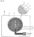
- FIG. 6 is a bottom view showing an electric heater according to a first embodiment of the present invention.
- the electric heater 210 may include a base 211, and a heating unit 221 having a plurality of unit heating elements 225, 235 each implemented as an electrical resistor and spaced from each other on a plate surface of the base 211, and non-heating connection portions 227, 237 conductively connecting the unit heating elements 225, 235 to each other.
- the heating unit 221 is provided with a first heating portion 222 disposed in a radiating direction, and a second heating portion 232 disposed radially inside of the first heating portion 222.
- the first heating portion 222 and the second heating portion 232 are respectively connected to first power connection portions 241 and second power connection portions 243 for separately being supplied with power.
- the first heating portion 222 is configured to have a plurality of unit heating elements 225 each having a bar shape and disposed outside the second heating portion 232 so that inner and outer ends thereof can respectively form circular shapes, and non-heating connection portions 227 configured not to heat and conductively connecting the unit heating elements 225 to each other.
- the second heating portion 232 is configured to have a plurality of unit heating elements 235 each having a bar shape and disposed parallel so that the outer ends thereof can form a circular shape, and non-heating connection portions 237 configured not to heat and conductively connecting the unit heating elements 235 to each other.
- Each of the unit heating elements 235 of the second heating portion 232 is formed to have a different length so that outer ends thereof can form a circular shape.
- the heating values of the first heating portion 222 and the second heating portion 232 may be appropriately controlled, by selectively connecting power to one of the first power connection portions 241 and the second power connection portions 243, or by simultaneously connecting to the first and second power connection portions 241, 243.
- each of the non-heating connection portions 227, 237 of the first and second heating portions 222, 232 does not have a high temperature when powered, thereby not generating cracking and dielectric breakdown as well as performing a stable operation even at a high power level.
- cooking utensils of different sizes may be heated by separately using the first and second heating portions 222, 232.
- first and second heating portions 222, 232 are simultaneously used, a cooking utensil of a large size can be quickly heated.
- each of the unit heating elements 225, 235 of the first and second heating portions 222, 232 has a bar shape, thereby preventing damage caused by a high temperature when cooking utensils are eccentrically positioned.
- FIG. 7 is a bottom view showing an electric heater according to a second embodiment of the present invention.
- the electric heater 250 according to the present invention may include a base 251, and a heating unit 261 having a plurality of unit heating elements 265, 275 each implemented as an electrical resistor and spaced from each other on a plate surface of the base 251, and non-heating connection portions 267, 277 conductively connecting the unit heating elements 265, 275 to each other.
- the base 251 is made of a glass member, and is formed to have a rectangular plate shape.
- the unit heating elements 265, 275 and the non-heating connection portions 267, 277 are disposed at a lower surface of the base 251.
- the heating unit 261 is provided with, according to its position, a first heating portion 262, and a second heating portion 272 disposed inside with respect to the first heating portion 262.
- the first heating portion 262 is provided with a plurality of unit heating elements 265 disposed outside of the second heating portion 272 in a radial shape, and non-heating connection portions 267 configured not to heat and conductively connecting the unit heating elements 265 to each other.
- the second heating portion 272 is provided with a plurality of unit heating elements 275 having an arc-shape and concentrically disposed with respect to each other, and non-heating connection portions 267 configured not to heat and conductively connecting the unit heating elements 275 to each other.
- the first and second heating portions 262, 272 are respectively connected to first power connection portions 281 and second power connection portions 283 so as to be connected to power.
- a control circuit (not shown) for selectively supplying power is respectively connected to the first and second heating portions 262, 272.
- the first and second heating portions 262, 272 are prevented from a temperature increase by the non-heating connection portions 267, 277, thereby preventing the occurrence of cracking and dielectric breakdown.
- the unit heating elements 265 of the first heating portion 262 have a relatively small non-contact area, which has no heat transfer with the cooking utensil. Thus, thermal/electrical damage due to a high temperature can be prevented.
- FIG 8 is a bottom view showing an electric heater according to a third exemplary embodiment.
- Figure 9 is a diagram showing an operation state when a cooking utensil is disposed eccentrically on the electric heater in Fig. 8 .
- the electric heater 310 may include a base 311, a plurality of unit heating elements 325, 335 each implemented as an electrical resistor and radially disposed on the base 311, and first and second power connection portions 371, 372 for supplying power to the unit heating elements 325, 335.
- the base 311 is made of a glass member, and is formed to have a rectangular plate shape. Cooking utensils may be placed on an upper surface of the base 311.
- a heating unit 320 is disposed at a lower surface of the base 311 so as to heat the cooking utensils when power is supplied.
- the heating unit 320 includes a first heating portion 321 disposed in a radiating direction, and a second heating portion 351 disposed radially inside with respect to the first heating portion 321.
- the first heating portion 321 is configured to have an outer heating section 322 disposed in a radiating direction, and an inner heating section 332 disposed radially inside of the outer heating section 322.
- the outer heating section 322 is provided with a plurality of unit heating elements 325 each formed to have a bar or rectangular plate shape and disposed radially, and heating connection portions 326 conductively connecting the unit heating elements 325 to each other and configured to heat when conducted.
- the unit heating elements 325 are each implemented as a heating element having a large electrical resistance value and are spaced from each other in a circumferential direction with a certain width and interval.
- the heating connection portions 326 may be integrally formed by using the same material as the unit heating elements 325 so as to heat when powered.
- the inner heating section 332 is provided with a plurality of unit heating elements 335 each having a bar or rectangular plate shape and radially disposed, and heating connection portions 336 conductively connecting the unit heating elements 335 to each other and being configured to heat when powered.
- the second heating portion 351 is provided with a plurality of unit heating elements 355 each having an arc shape and spaced from each other in a radial direction, and heating connection portions 356 connecting the unit heating elements 355.
- first and second heating portions 321, 351 are respectively connected to first power connection portions 371 and second power connection portions 373 so as to be connected to power.
- a control circuit (not shown) is respectively connected to the first and second power connection portions 371, 373.
- the control circuit may be configured to control a heating value by allowing the first and second heating portions 321, 351 to heat simultaneously or according to its connected state.
- FIG 10 is a bottom view showing an electric heater according to a fourth exemplary embodiment.
- Figure 11 is a diagram showing an operation state when a cooking utensil is disposed eccentrically on the electric heater in Fig. 10 .
- the electric heater 410 may include a base 411, and first and second heating units 421, 431 spaced from each other in a radial direction on a plate surface of the base 411. And, the first and second heating units 421, 431 are provided with unit heating elements 425, 435 disposed radially, and connection portions 426, 436 conductively connecting the unit heating elements 425, 435 to each other.
- the unit heating elements 425, 435 are each implemented as a heating element, and the connection portions 426, 436, as a heating element, are integrally formed with the unit heating elements 425, 435, thereby heating when powered.
- the unit heating elements 425 when a cooking utensil is placed eccentrically on an upper surface of the base 411, the unit heating elements 425 have a relatively small interface between an area contacting a bottom of the cooking utensil and a non-contact area, thereby having a small temperature increase and preventing damage due to a temperature increase.
- the second heating unit 431 when the second heating unit 431 is used to heat a relatively small-sized cooking utensil, as shown in the dashed line 441 in Fig. 11 , even though the cooking utensil is placed eccentrically, the unit heating elements 435 of the second heating unit 431 are radially disposed. Accordingly, the interface between a contact area 442 contacting the cooking utensil and a non-contact area 443 not contacting the cooking utensil becomes small, thereby preventing damage due to a temperature increase.
- FIG 12 is a bottom view showing an electric heater according to a third embodiment of the present invention.
- the electric heater 510 may include a base 511, and a heating unit having a first and second heating portions 521, 531 spaced from each other in a radial direction on a plate surface of the base 511. And, the first and second heating portions 521, 531 are provided with radially disposed unit heating elements 525, 535, and non-heating connection portions 526, 536 conductively connecting the unit heating elements 525, 535 to each other.
- the unit heating elements 525, 535 are each implemented as a heating element, and the non-heating connection portions 526, 536 are formed of a material having a small heating value (e.g., Ag, silver alloy, etc.) compared to the heating elements, not so as to generate heat when powered.
- the first heating portion 521 and the second heating portion 531 are connected to first power connection portions 541 and second power connection portions 542, respectively, for separately receiving a power.
- the unit heating elements 525 of the first heating portion 521 being radially disposed, thereby form only a small interface between a contact area contacting with the cooking utensil and a non-contact area. Accordingly, the temperature does not increase too high, and damage due to a temperature increase can be prevented.
- the unit heating elements 535 of the second heating portion 531 being radially disposed, thereby form a small interface between a contact area contacting with the cooking utensil and a non-contact area , thus to prevent damage due to a temperature increase.
- non-heating connection portions 526, 536 connecting the unit heating elements 525, 535 of the first and second heating portions 521, 531 generate less heat when powered. Therefore, even though a thermal stress concentration is focussed thereat, the temperature is not too high, thereby not generating cracking and/or di-electric breakdown, thus to stably operate even at a relatively high level power.
- the electric heater according to the present invention may be used for cooking utensils such as an electric rice-cooker, an electric kettle as well as for so-called "cook-tops" disposed on a kitchen counter and/or a table of a kitchen.
- the electric heater according to the present invention may be used for electric appliances such as an electric iron, a dish washer, a drum washing machine and/or a heating mat, beauty aid as well as an industrial electric heater.
Landscapes
- Chemical & Material Sciences (AREA)
- Engineering & Computer Science (AREA)
- Ceramic Engineering (AREA)
- Resistance Heating (AREA)
- Electric Stoves And Ranges (AREA)
Description
- The present invention relates to an electric heater, and more particularly, to an electric heater which is capable of preventing damage to a heating unit.
- In general, an electric heater is a heating apparatus which uses heat generated when a current is conducted through a heating element. Electric heaters are typically manufactured by winding or processing heating wires in a specific shape. For instance, the electric heaters may have a structure, in which heating wires wound onto a mica plate or wound in a certain shape are placed inside a quartz tube, or in which a specific material is filled between heating wires and a stainless tube having a certain distance therebetween after the heating wires are placed in the stainless tube.
- The related art electric heater, i.e., the heater using the heating wires, may have a problem of oxidation caused by direct contacting by air when heated as well as a structural problem to support the heating wires.
- Considering these problems, a so-called plane heater which is formed by coating a heating element onto a substrate of a ceramic, glass, aluminum, stainless steel, etc. has recently been used. Such a plane heater facilitates a space utilization due to its thinness, and is good for an instantaneous heating due to its short heat transfer path, thereby being increasingly used.
-
Figure 1 is an exemplary perspective view of a related art electric heater, andFigure 2 is an enlarged view showing the main parts of the electric heater inFig. 1 . As shown in the drawings, anelectric heater 20 may include a plate-shaped base 21 installed to be exposed on an upper surface of a table or akitchen counter 10, or the like, aheating unit 31 formed on a surface of thebase 21, and apower connection unit 41 for supplying power to theheating unit 31. - The
base 21 is made of a glass member and is formed to have a plate shape. Generally, cooking utensils (not shown) are placed on the surface of thebase 21, i.e., on an upper surface of thebase 21. Theheating unit 31 and thepower connection unit 41 are disposed at another surface of thebase 21, i.e., at a lower surface of thebase 21. Indication lines 22 for indicating the positions where the cooking utensils are to be placed and a plurality ofmanipulation buttons 24 for manipulating theheating unit 31, are provided on the upper surface of thebase 21. - Further, the
heating unit 31 may include an electric resistor implemented as arc-shaped portions 32 and concentrically spaced from each other in a radial direction from the central portion, and curvedportions 33 for connecting the arc-shaped portions 32, thereby forming a consecutively connected curved line shape. Theheating unit 31 is connected to thepower connection unit 41 so as to be connected to the mains power. - However, in the related art electric heater, when the
heating unit 31 is formed in the consecutively curved line shape, a plurality ofcurved portions 33 having a relatively small curvature (radius of curvature) are formed, which easily leads to a thermal stress concentration therein. Accordingly, cracking, dielectric breakdown, etc. may easily occur at thecurved portions 33 or at a periphery of thecurved portions 33, compared to at the arc-shaped portions 31 or at a periphery of the arc-shaped portions 31, thus to cause a problem of reducing its service life. -
Figure 3 is an exemplary bottom view showing another related art electric heater. As shown inFig. 3 , anelectric heater 50 may include abase 51 disposed to be exposed on an upper surface of a kitchen counter, a table, etc., and aheating unit 61 disposed on a plate surface of thebase 51. - The
heating unit 61 configured to heat a cooking utensil is formed at another surface of thebase 51, i.e., at a lower surface thereof. Theheating unit 61 may include arc-shaped portions 63 having an arc shape and concentrically disposed with respect to each other, and connectingportions 65 connecting the arc-shaped portions 63. Theheating unit 61 is connected to apower connection unit 71 so as to be connected to the mains power. Theheating unit 61, i.e., the arc-shaped portions 63 and theconnection portions 65 are implemented as an electric resistor having a large electrical resistance value. - Meanwhile, the cooking utensil may be placed eccentrically, without being aligned onto the center of the
heating unit 61. As shown in thedashed line 67 inFig. 3 , if the cooking utensil is placed eccentrically, theheating unit 61 may be divided into two areas comprised of acontact area 68 contacted by the cooking utensil and capable of heat conduction to the cooking utensil, and anon-contact area 69 not contacted by the cooking utensil and thusly incapable of heat conduction to the cooking utensil. Here, the interface formed between thecontact area 68 and thenon-contact area 69 increases the probability of a thermal/electrical breakdown due to an increase in the temperature gradient. - In the related art electric heater, however, the
heating unit 61 is concentrically disposed in a long-and-thin arc shape. Thus, the interface between thecontact area 68 and thenon-contact area 69 becomes long, thereby increasing the probability of a thermal/electrical breakdown. Accordingly, damage or cracking easily occurs, thus to reduce its life. - In addition, the
connection portions 65 connecting the arc-shaped portions 63 are structured to have a relatively small radius of curvature, thereby causing a concentration of the thermal stress (or temperature stress), thus to generate cracking or a dielectric breakdown even at a relatively low power level. Accordingly, there is a limit to enhance the output by more than a certain level. - In
US4002883 an electrical heating unit is disclosed having a flat utensil-supporting plate of glass-ceramic or other electrical non-conductive material. On the underside of this plate are bonded multiple undulating coil electrical resistance film heaters arranged in a generally closed loop. Each coil or loop is of substantially equal length to have about the same watts density and provide a generally uniform temperature distribution over the top surface of the heating unit. - In
WO 96/17496 -
EP 1161120 A2 relates to a thick film electric heater comprising an insulating substrate provided with a thick film resistive heating track. The resistive track comprises at least two discrete sections connected by a bridge of a material having a resistivity lower than that of the resistive track, such as silver. - Therefore, it is an object of the present invention to provide an electric heater which can prevent damage to a heating unit.
- It is another object of the present invention to provide an electric heater which can prevent damage to a heating unit by controlling a thermal stress concentration and can enhance the output of the electric heater.
- It is another object of the present invention to provide an electric heater which can prevent damage to a heating unit due to eccentric placement of a cooking utensil.
- This object is solved by the features of the independent claim 1.
- To achieve these and other advantages and in accordance with the purpose of the present invention, as embodied and broadly described herein, there is provided an electric heater, including: a base; and a heating unit having a plurality of unit heating elements disposed on a plate surface of the base, and at least one of heating connection portions configured to heat and conductively connecting the unit heating elements to each other and non-heating connection portions configured not to heat and conductively connecting the unit heating elements to each other.
- Further, the unit heating elements may be disposed radially.
- In addition, the unit heating elements are connected to a first power connection portion for supplying power.
- Also, the unit heating elements may be formed to have a linear or curved line shape.
- Also, the heating unit may include a first heating portion, and a second heating portion disposed inside the first heating portion.
- Further, the second heating portion may have unit heating elements in a linear or curved line shape.
- Further, the unit heating elements of the second heating portion may be connected by non-heating connection portions configured not to heat.
- Also, the second heating portion may further include a second power connection portion for supplying power.
- In the drawings:
-
Figure 1 is a plan view showing an installation of a related art electric heater; -
Figure 2 is an enlarged view showing main parts of the electric heater inFig. 1 ; -
Figure 3 is an exemplary bottom view showing another related art electric heater; -
Figure 4 is a bottom view showing an electric heater according to a first exemplary embodiment; -
Figure 5 is a bottom view showing an electric heater according to a second exemplary embodiment; -
Figure 6 is a bottom view showing an electric heater according to a first embodiment of the present invention; -
Figure 7 is a bottom view showing an electric heater according to a second embodiment of the present invention; -
Figure 8 is a bottom view showing an electric heater according to a third exemplary embodiment; -
Figure 9 is a diagram showing an operation state when a cooking utensil is eccentrically disposed on the electric heater inFig. 8 ; -
Figure 10 is a bottom view showing an electric heater according to a fourth exemplary embodiment; -
Figure 11 is a diagram showing an operation state when a cooking utensil is eccentrically disposed on the electric heater inFig. 10 ; and -
Figure 12 is a bottom view showing an electric heater according to a third embodiment of the present invention. - Reference will now be made in detail to embodiments of the present disclosure, examples of which are illustrated in the accompanying drawings.
- Hereinafter, an electric heater according to the present invention will be explained.
-
Figure 4 is a bottom view showing an electric heater according to a first exemplary embodiment. As shown in the drawing, theelectric heater 110 may include abase 111, and aheating unit 121 having a plurality ofunit heating elements 123 each implemented as an electrical resistor and spaced from each other on a plate surface of thebase 111, andnon-heating connection portions 125 conductively connecting theunit heating elements 123 to each other. - The
base 111 is made of a glass member and is formed to have a rectangular plate shape. Cooking utensils, etc. may be placed on a surface of thebase 111, i.e., on an upper surface thereof. Theunit heating elements 123 and thenon-heating connection portions 125 are formed by a method of coating, etc. at another surface of thebase 111, i.e., at a lower surface thereof. Here, thebase 111 may be formed of a stainless steel, ceramic, aluminum, or the like. Theheating unit 121 is disposed to be insulated with thebase 111. - The
heating unit 121 is provided with the plurality ofunit heating elements 123 in a circular ring shape having one end thereof open and concentrically disposed to each other, and thenon-heating connection portions 125 conductively connecting theunit heating elements 123 to each other. Each of theunit heating elements 123 has a uniform width, and is spaced from one another with a certain gap therebetween. This is to uniformly heat over the entire area. - Meanwhile, the
non-heating connection portions 125 are formed of a material having a low electrical resistance (e.g., Ag, silver alloy, etc.), compared to theunit heating elements 123. This is to reduce a heating value when powered, compared to theunit heating elements 123, thereby preventing cracking and/or dielectric breakdown due to a temperature increase in the connection area of theheating unit 121 when heated. - A plurality of
heating units 121 may be provided so as to control the heating value. Each of theheating units 121 is connected to respectivepower connection units 127 for supplying power. A control circuit (not shown) for controlling theheating units 121 is respectively connected to thepower connection units 127. This is to supply power either separately or simultaneously, by a combination of thepower connection units 127, and thus to allow each of theheating units 121 to heat individually or simultaneously, thereby controlling the heating value according to a cooking type or cooked status. It should be noted that thepower connection units 127 are not for heating, but for power supply. Accordingly, thepower connection units 127 may be formed of the same material as thenon-heating connection portions 125. - With this construction, the
non-heating connection portions 125 have a small heating value when powered, thereby not causing cracking and dielectric breakdown due to a temperature increase. Based on this, an operation may be stably performed even at a relatively high power level, thereby enhancing the capacity of the electric heater. -
Figure 5 is a bottom view showing an electric heater according to a second exemplary embodiment. As shown in the drawing, theelectric heater 150 may include abase 151, and aheating unit 161 having a plurality ofunit heating elements 165 each implemented as an electrical resistor and spaced from each other on a plate surface of thebase 151, andnon-heating connection portions 167 conductively connecting theunit heating elements 165 to each other. Here, thebase 151 is formed of a glass member, and thenon-heating connection portions 167 are formed of a material having a low electrical resistance (e.g., Ag, silver alloy, etc.) so as to have a small heating value, compared to theunit heating elements 165 implemented as electrical resistors. - The
unit heating elements 165 are each formed to have a bar shape having a certain width and length, and are disposed in parallel. This is to prevent a damage due to a temperature gradient in case a cooking utensil is eccentrically placed with respect to theunit heating elements 165. That is, as shown in the dashedcircle 171 inFig. 5 , when a cooking utensil is eccentrically placed, some of theunit heating elements 165 have an interface between acontact area 172 having heat transfer with the cooking utensil and anon-contact area 173 having no heat transfer. Here, theunit heating elements 165 are formed to have a bar shape, thereby reducing the size of the interface and also preventing the occurrence of thermal/electrical damage due to a temperature gradient increase at the interface. - Meanwhile, the
heating unit 161 is provided with afirst heating portion 162a and asecond heating portion 162b for being separately supplied with power so as to control the heating value. Thefirst heating portion 162a and thesecond heating portion 162b are respectively connected to firstpower connection portions 181 and secondpower connection portions 183 so as to be connected to the power. Here, the firstpower connection portions 181 and the secondpower connection portions 183 may be connected to the power selectively or simultaneously, thereby controlling the heating value. - With this construction, the
non-heating connection portions 167 of both thefirst heating portion 162a and thesecond heating portion 162b have a relatively small heating value when powered. Accordingly, the temperature does not increase too high, thus to prevent the occurrence of cracking and dielectric breakdown due to a high temperature. Meanwhile, the first andsecond heating portions unit heating elements 165 of both thefirst heating portion 162a and thesecond heating portion 162b are formed to have a bar shape, in case a cooking utensil is eccentrically placed, damage caused by a temperature increase can be prevented. -
Figure 6 is a bottom view showing an electric heater according to a first embodiment of the present invention. As shown in the drawing, theelectric heater 210 according to the present invention may include abase 211, and aheating unit 221 having a plurality ofunit heating elements base 211, andnon-heating connection portions unit heating elements - The
heating unit 221 is provided with afirst heating portion 222 disposed in a radiating direction, and asecond heating portion 232 disposed radially inside of thefirst heating portion 222. Thefirst heating portion 222 and thesecond heating portion 232 are respectively connected to firstpower connection portions 241 and secondpower connection portions 243 for separately being supplied with power. - Meanwhile, the
first heating portion 222 is configured to have a plurality ofunit heating elements 225 each having a bar shape and disposed outside thesecond heating portion 232 so that inner and outer ends thereof can respectively form circular shapes, andnon-heating connection portions 227 configured not to heat and conductively connecting theunit heating elements 225 to each other. - The
second heating portion 232 is configured to have a plurality ofunit heating elements 235 each having a bar shape and disposed parallel so that the outer ends thereof can form a circular shape, andnon-heating connection portions 237 configured not to heat and conductively connecting theunit heating elements 235 to each other. Each of theunit heating elements 235 of thesecond heating portion 232 is formed to have a different length so that outer ends thereof can form a circular shape. - The heating values of the
first heating portion 222 and thesecond heating portion 232 may be appropriately controlled, by selectively connecting power to one of the firstpower connection portions 241 and the secondpower connection portions 243, or by simultaneously connecting to the first and secondpower connection portions - With such configuration, each of the
non-heating connection portions second heating portions second heating portions second heating portions unit heating elements second heating portions -
Figure 7 is a bottom view showing an electric heater according to a second embodiment of the present invention. As shown in the drawing, theelectric heater 250 according to the present invention may include abase 251, and aheating unit 261 having a plurality ofunit heating elements base 251, andnon-heating connection portions unit heating elements - The
base 251 is made of a glass member, and is formed to have a rectangular plate shape. Theunit heating elements non-heating connection portions base 251. - The
heating unit 261 is provided with, according to its position, afirst heating portion 262, and asecond heating portion 272 disposed inside with respect to thefirst heating portion 262. - The
first heating portion 262 is provided with a plurality ofunit heating elements 265 disposed outside of thesecond heating portion 272 in a radial shape, andnon-heating connection portions 267 configured not to heat and conductively connecting theunit heating elements 265 to each other. - The
second heating portion 272 is provided with a plurality ofunit heating elements 275 having an arc-shape and concentrically disposed with respect to each other, andnon-heating connection portions 267 configured not to heat and conductively connecting theunit heating elements 275 to each other. - The first and
second heating portions power connection portions 281 and secondpower connection portions 283 so as to be connected to power. A control circuit (not shown) for selectively supplying power is respectively connected to the first andsecond heating portions - With such configuration, the first and
second heating portions non-heating connection portions unit heating elements 265 of thefirst heating portion 262 have a relatively small non-contact area, which has no heat transfer with the cooking utensil. Thus, thermal/electrical damage due to a high temperature can be prevented. -
Figure 8 is a bottom view showing an electric heater according to a third exemplary embodiment.Figure 9 is a diagram showing an operation state when a cooking utensil is disposed eccentrically on the electric heater inFig. 8 . As shown in the drawings, theelectric heater 310 may include abase 311, a plurality ofunit heating elements base 311, and first and secondpower connection portions unit heating elements - The
base 311 is made of a glass member, and is formed to have a rectangular plate shape. Cooking utensils may be placed on an upper surface of thebase 311. - Further, a
heating unit 320 is disposed at a lower surface of the base 311 so as to heat the cooking utensils when power is supplied. Theheating unit 320 includes afirst heating portion 321 disposed in a radiating direction, and asecond heating portion 351 disposed radially inside with respect to thefirst heating portion 321. - The
first heating portion 321 is configured to have anouter heating section 322 disposed in a radiating direction, and aninner heating section 332 disposed radially inside of theouter heating section 322. Theouter heating section 322 is provided with a plurality ofunit heating elements 325 each formed to have a bar or rectangular plate shape and disposed radially, andheating connection portions 326 conductively connecting theunit heating elements 325 to each other and configured to heat when conducted. Theunit heating elements 325 are each implemented as a heating element having a large electrical resistance value and are spaced from each other in a circumferential direction with a certain width and interval. Theheating connection portions 326 may be integrally formed by using the same material as theunit heating elements 325 so as to heat when powered. - The
inner heating section 332 is provided with a plurality ofunit heating elements 335 each having a bar or rectangular plate shape and radially disposed, andheating connection portions 336 conductively connecting theunit heating elements 335 to each other and being configured to heat when powered. - The
second heating portion 351 is provided with a plurality ofunit heating elements 355 each having an arc shape and spaced from each other in a radial direction, andheating connection portions 356 connecting theunit heating elements 355. - Further, the first and
second heating portions power connection portions 371 and secondpower connection portions 373 so as to be connected to power. A control circuit (not shown) is respectively connected to the first and secondpower connection portions second heating portions - With such construction, when cooking utensil is eccentrically placed on an upper surface of the
base 311, as shown in the dashedline 341 inFig. 9 , theunit heating elements first heating portion 321 are radially disposed. Accordingly, only a very short interface is formed between acontact area 342 of theunit heating elements 325 contacting the cooking utensil and anon-contact area 343, thereby preventing the occurrence of cracking and dielectric breakdown, by reducing the probability of a localized hot spot. -
Figure 10 is a bottom view showing an electric heater according to a fourth exemplary embodiment.Figure 11 is a diagram showing an operation state when a cooking utensil is disposed eccentrically on the electric heater inFig. 10 . As shown in the drawings, theelectric heater 410 may include abase 411, and first andsecond heating units base 411. And, the first andsecond heating units unit heating elements connection portions unit heating elements - The
unit heating elements connection portions unit heating elements - With such construction, when a cooking utensil is placed eccentrically on an upper surface of the
base 411, theunit heating elements 425 have a relatively small interface between an area contacting a bottom of the cooking utensil and a non-contact area, thereby having a small temperature increase and preventing damage due to a temperature increase. In addition, when thesecond heating unit 431 is used to heat a relatively small-sized cooking utensil, as shown in the dashedline 441 inFig. 11 , even though the cooking utensil is placed eccentrically, theunit heating elements 435 of thesecond heating unit 431 are radially disposed. Accordingly, the interface between acontact area 442 contacting the cooking utensil and anon-contact area 443 not contacting the cooking utensil becomes small, thereby preventing damage due to a temperature increase. -
Figure 12 is a bottom view showing an electric heater according to a third embodiment of the present invention. As shown in the drawing, theelectric heater 510 according to the present invention may include abase 511, and a heating unit having a first andsecond heating portions base 511. And, the first andsecond heating portions unit heating elements non-heating connection portions unit heating elements - The
unit heating elements non-heating connection portions first heating portion 521 and thesecond heating portion 531 are connected to firstpower connection portions 541 and secondpower connection portions 542, respectively, for separately receiving a power. - With such configuration, when a cooking utensil is disposed eccentrically on the upper surface of the
base 511, theunit heating elements 525 of thefirst heating portion 521, being radially disposed, thereby form only a small interface between a contact area contacting with the cooking utensil and a non-contact area. Accordingly, the temperature does not increase too high, and damage due to a temperature increase can be prevented. - Also, when the
second heating portion 531 is used for a small-sized cooking utensil, even if the cooking utensil is disposed eccentrically, theunit heating elements 535 of thesecond heating portion 531, being radially disposed, thereby form a small interface between a contact area contacting with the cooking utensil and a non-contact area , thus to prevent damage due to a temperature increase. - In addition, the
non-heating connection portions unit heating elements second heating portions - The foregoing embodiments and advantages are merely exemplary and are not to be construed as limiting the present disclosure. The present teachings can be readily applied to other types of apparatuses. This description is intended to be illustrative, and not to limit the scope of the claims. Many alternatives, modifications, and variations will be apparent to those skilled in the art. The features, structures, methods, and other characteristics of the exemplary embodiments described herein may be combined in various ways to obtain additional and/or alternative exemplary embodiments.
- As the present features may be embodied in several forms without departing from the characteristics thereof, it should also be understood that the above-described embodiments are not limited by any of the details of the foregoing description, unless otherwise specified, but rather should be construed broadly within its scope as defined in the appended claims, and therefore all changes and modifications that fall within the metes and bounds of the claims, or equivalents of such metes and bounds are therefore intended to be embraced by the appended claims.
- The electric heater according to the present invention may be used for cooking utensils such as an electric rice-cooker, an electric kettle as well as for so-called "cook-tops" disposed on a kitchen counter and/or a table of a kitchen.
- The electric heater according to the present invention may be used for electric appliances such as an electric iron, a dish washer, a drum washing machine and/or a heating mat, beauty aid as well as an industrial electric heater.
Claims (7)
- An electric heater, comprising:a base (211, 251, 511); anda heatingunit (221, 261), the heating unit (221, 261)havinga plurality of unit heating elements (225, 235, 265, 275,525,535) disposed on a plate surface of the base (211, 251,511), and at least one non-heating connection portion (227, 237, 267, 277, 526, 536) configured not to heat and conductively connecting the unit heating elements (225, 235, 265, 275, 525, 535)to each other;characterized in that the heating unit (221, 261) further comprises:a first heating portion (222, 262, 521) of which inner and outer ends thereof form circular shapes and provided with the plurality of unit heating elements (225, 265, 525), each unit heating elements (225, 265, 525) having a bar shape, anda second heating portion (232, 272, 531) disposed radially inside of the first heating portion (222, 262, 521);wherein the non-heating connection portion (227,237, 267, 277, 526, 536,) is formed of a material having a low electrical resistance compared to the unit heating elements (225, 235, 265, 275, 525, 535).
- The electric heater of claim 1, wherein the unit heating elements (225, 235, 265, 275, 525, 535) are formed to have a uniform width.
- The electric heater of claim 1, wherein the unit heating
elements (225, 235, 265, 275, 525, 535) are spaced from each other by a predetermined interval. - The electric heater of claim 1, further comprising:a first power connection portion (241, 281, 541) for supplying power to the unit heating elements of the first heating portion (222, 262, 521).
- The electric heater of claim 1, further comprising:first (241, 281, 541) and second (243, 283, 542) power connection portions for respectively supplying power to the first (222, 262, 521) and second (232, 272, 531) heating portions.
- The electric heater of claim 1, wherein the second heating portion (232) is provided with a plurality of unit heating elements (225) formed to have a bar shape and disposed such that outer ends thereof form a circular shape.
- The electric heater of claim 1, wherein the second heating portion (272) is provided with a plurality of unit heating elements (275) having an arc shape and disposed concentrically to each other.
Applications Claiming Priority (3)
| Application Number | Priority Date | Filing Date | Title |
|---|---|---|---|
| KR1020070073024A KR101378881B1 (en) | 2007-07-20 | 2007-07-20 | Electric heater |
| KR1020070073022A KR101412578B1 (en) | 2007-07-20 | 2007-07-20 | Electric heater |
| PCT/KR2008/004121 WO2009014333A1 (en) | 2007-07-20 | 2008-07-14 | Electric heater |
Publications (3)
| Publication Number | Publication Date |
|---|---|
| EP2186380A1 EP2186380A1 (en) | 2010-05-19 |
| EP2186380A4 EP2186380A4 (en) | 2012-05-09 |
| EP2186380B1 true EP2186380B1 (en) | 2016-06-22 |
Family
ID=40281543
Family Applications (1)
| Application Number | Title | Priority Date | Filing Date |
|---|---|---|---|
| EP08778779.2A Revoked EP2186380B1 (en) | 2007-07-20 | 2008-07-14 | Electric heater |
Country Status (3)
| Country | Link |
|---|---|
| US (1) | US8269150B2 (en) |
| EP (1) | EP2186380B1 (en) |
| WO (1) | WO2009014333A1 (en) |
Families Citing this family (20)
| Publication number | Priority date | Publication date | Assignee | Title |
|---|---|---|---|---|
| JP6758143B2 (en) * | 2016-09-29 | 2020-09-23 | 日本特殊陶業株式会社 | Heating device |
| JP6767833B2 (en) * | 2016-09-29 | 2020-10-14 | 日本特殊陶業株式会社 | Heating device |
| US10679873B2 (en) * | 2016-09-30 | 2020-06-09 | Ngk Spark Plug Co., Ltd. | Ceramic heater |
| EP3451791B1 (en) * | 2017-09-04 | 2020-03-25 | E.G.O. Elektro-Gerätebau GmbH | Heater and method for manufacturing same |
| DE102017222958A1 (en) | 2017-09-04 | 2019-03-07 | E.G.O. Elektro-Gerätebau GmbH | Heating device and method for producing a heating device |
| KR102091251B1 (en) * | 2018-08-21 | 2020-03-19 | 엘지전자 주식회사 | Electric Heater |
| KR102056084B1 (en) | 2018-08-21 | 2019-12-16 | 엘지전자 주식회사 | Electric Heater |
| KR102159802B1 (en) | 2018-08-21 | 2020-09-25 | 엘지전자 주식회사 | Electric Heater |
| KR102159800B1 (en) * | 2018-08-21 | 2020-09-25 | 엘지전자 주식회사 | Electric Heater |
| KR102110417B1 (en) * | 2018-08-21 | 2020-05-13 | 엘지전자 주식회사 | Electric Heater |
| KR102110410B1 (en) * | 2018-08-21 | 2020-05-14 | 엘지전자 주식회사 | Electric Heater |
| KR102123677B1 (en) * | 2018-08-21 | 2020-06-17 | 엘지전자 주식회사 | Electric Heater |
| KR102048733B1 (en) * | 2018-08-21 | 2019-11-27 | 엘지전자 주식회사 | Electric Heater |
| KR102111332B1 (en) * | 2018-10-11 | 2020-05-15 | 엘지전자 주식회사 | Electric Heater |
| KR102177948B1 (en) * | 2018-10-16 | 2020-11-12 | 엘지전자 주식회사 | Electric Heater |
| CN110167207A (en) * | 2019-07-02 | 2019-08-23 | 厦门美图之家科技有限公司 | Beauty instrument and method for heating and controlling |
| EP3764738B1 (en) * | 2019-07-11 | 2024-02-07 | Vorwerk & Co. Interholding GmbH | Food preparation device with ptc resistors in parallel |
| US11371748B2 (en) | 2019-08-05 | 2022-06-28 | The Merchant Of Tennis, Inc. | Portable heater with ceramic substrate |
| JP2022109781A (en) * | 2021-01-15 | 2022-07-28 | 東芝ライテック株式会社 | Heater, and image forming apparatus |
| KR102561807B1 (en) * | 2022-05-13 | 2023-08-01 | 주식회사 미코세라믹스 | Ceramic heater |
Citations (8)
| Publication number | Priority date | Publication date | Assignee | Title |
|---|---|---|---|---|
| GB860213A (en) | 1958-08-08 | 1961-02-01 | Allen William Baldwin | Improvements in or relating to electrical heating elements |
| US4002883A (en) | 1975-07-23 | 1977-01-11 | General Electric Company | Glass-ceramic plate with multiple coil film heaters |
| WO1996017496A1 (en) | 1994-11-26 | 1996-06-06 | Pifco Limited | Improvements to thick film elements |
| EP0853444A2 (en) | 1997-01-10 | 1998-07-15 | E.G.O. ELEKTRO-GERÄTEBAU GmbH | Cooking system with an electric cooking-plate, transferring heat by conduction |
| EP1161120A2 (en) * | 1997-02-17 | 2001-12-05 | Strix Limited | Electric heaters |
| DE10356790A1 (en) | 2003-12-04 | 2005-07-07 | BSH Bosch und Siemens Hausgeräte GmbH | Heating device for fluids, water heaters and process for their preparation |
| WO2007008705A2 (en) | 2005-07-09 | 2007-01-18 | Aviza Technology, Inc. | Uniform batch film deposition process and films so produced |
| WO2007008075A2 (en) * | 2005-07-11 | 2007-01-18 | Ferro Techniek Holding B.V. | Heating element for application in a device for heating liquids |
Family Cites Families (7)
| Publication number | Priority date | Publication date | Assignee | Title |
|---|---|---|---|---|
| JP2948357B2 (en) | 1991-05-14 | 1999-09-13 | 信越化学工業株式会社 | Multilayer ceramic heater |
| JPH10213981A (en) | 1997-01-30 | 1998-08-11 | Canon Inc | Heating fixing heater |
| US6616767B2 (en) * | 1997-02-12 | 2003-09-09 | Applied Materials, Inc. | High temperature ceramic heater assembly with RF capability |
| JP4040814B2 (en) * | 1998-11-30 | 2008-01-30 | 株式会社小松製作所 | Disk heater and temperature control device |
| KR100431655B1 (en) * | 2001-08-28 | 2004-05-17 | 삼성전자주식회사 | Heater assembly for heating a wafer |
| JP3856293B2 (en) * | 2001-10-17 | 2006-12-13 | 日本碍子株式会社 | Heating device |
| JP4806179B2 (en) * | 2004-10-08 | 2011-11-02 | 古河スカイ株式会社 | Heater plate manufacturing method |
-
2008
- 2008-07-14 EP EP08778779.2A patent/EP2186380B1/en not_active Revoked
- 2008-07-14 WO PCT/KR2008/004121 patent/WO2009014333A1/en not_active Ceased
- 2008-07-14 US US12/669,622 patent/US8269150B2/en active Active
Patent Citations (8)
| Publication number | Priority date | Publication date | Assignee | Title |
|---|---|---|---|---|
| GB860213A (en) | 1958-08-08 | 1961-02-01 | Allen William Baldwin | Improvements in or relating to electrical heating elements |
| US4002883A (en) | 1975-07-23 | 1977-01-11 | General Electric Company | Glass-ceramic plate with multiple coil film heaters |
| WO1996017496A1 (en) | 1994-11-26 | 1996-06-06 | Pifco Limited | Improvements to thick film elements |
| EP0853444A2 (en) | 1997-01-10 | 1998-07-15 | E.G.O. ELEKTRO-GERÄTEBAU GmbH | Cooking system with an electric cooking-plate, transferring heat by conduction |
| EP1161120A2 (en) * | 1997-02-17 | 2001-12-05 | Strix Limited | Electric heaters |
| DE10356790A1 (en) | 2003-12-04 | 2005-07-07 | BSH Bosch und Siemens Hausgeräte GmbH | Heating device for fluids, water heaters and process for their preparation |
| WO2007008705A2 (en) | 2005-07-09 | 2007-01-18 | Aviza Technology, Inc. | Uniform batch film deposition process and films so produced |
| WO2007008075A2 (en) * | 2005-07-11 | 2007-01-18 | Ferro Techniek Holding B.V. | Heating element for application in a device for heating liquids |
Also Published As
| Publication number | Publication date |
|---|---|
| US20100193502A1 (en) | 2010-08-05 |
| US8269150B2 (en) | 2012-09-18 |
| EP2186380A1 (en) | 2010-05-19 |
| WO2009014333A1 (en) | 2009-01-29 |
| EP2186380A4 (en) | 2012-05-09 |
Similar Documents
| Publication | Publication Date | Title |
|---|---|---|
| US8269150B2 (en) | Electric heater | |
| EP0830803B1 (en) | Electrical heating elements | |
| EP3614807B1 (en) | Electric heater | |
| EP3614805B1 (en) | Electric heater | |
| US20230266015A1 (en) | Electric Heater And Cooking Appliance Having Same | |
| KR102690907B1 (en) | Induction heater for countertop | |
| KR20200021783A (en) | Electric Heater | |
| US20160010873A1 (en) | High performance surface unit for heating | |
| US11638330B2 (en) | Food preparation apparatus with electrical PTC thermistors connected in parallel | |
| KR101470395B1 (en) | Heating device for instant warm water | |
| KR20090009600A (en) | Electric heater | |
| KR20200021796A (en) | Electric Heater | |
| JP2011523174A (en) | Self-regulating electric resistance heating element | |
| KR101412578B1 (en) | Electric heater | |
| CN101437334B (en) | Induction heating cooking device | |
| KR20100011873U (en) | Electric range having circular ceramic heater | |
| EP2099343B1 (en) | Cooking device | |
| CN111656864B (en) | Induction heater for furnace roof | |
| GB2280578A (en) | Dual portion heating element | |
| CN210093592U (en) | Flat thick film heater of electric cooker | |
| JP4231803B2 (en) | Induction heating cooker | |
| EP0855131A1 (en) | Electric heaters | |
| JP4843460B2 (en) | Induction heating cooker | |
| CN113749507A (en) | Pot base module for kitchen machines | |
| GB2347058A (en) | Resistive track heater having intermediate electrical connection locations |
Legal Events
| Date | Code | Title | Description |
|---|---|---|---|
| PUAI | Public reference made under article 153(3) epc to a published international application that has entered the european phase |
Free format text: ORIGINAL CODE: 0009012 |
|
| 17P | Request for examination filed |
Effective date: 20100219 |
|
| AK | Designated contracting states |
Kind code of ref document: A1 Designated state(s): AT BE BG CH CY CZ DE DK EE ES FI FR GB GR HR HU IE IS IT LI LT LU LV MC MT NL NO PL PT RO SE SI SK TR |
|
| AX | Request for extension of the european patent |
Extension state: AL BA MK RS |
|
| DAX | Request for extension of the european patent (deleted) | ||
| A4 | Supplementary search report drawn up and despatched |
Effective date: 20120405 |
|
| RIC1 | Information provided on ipc code assigned before grant |
Ipc: H05B 3/16 20060101AFI20120330BHEP |
|
| 17Q | First examination report despatched |
Effective date: 20130927 |
|
| GRAP | Despatch of communication of intention to grant a patent |
Free format text: ORIGINAL CODE: EPIDOSNIGR1 |
|
| INTG | Intention to grant announced |
Effective date: 20160107 |
|
| GRAS | Grant fee paid |
Free format text: ORIGINAL CODE: EPIDOSNIGR3 |
|
| GRAA | (expected) grant |
Free format text: ORIGINAL CODE: 0009210 |
|
| AK | Designated contracting states |
Kind code of ref document: B1 Designated state(s): AT BE BG CH CY CZ DE DK EE ES FI FR GB GR HR HU IE IS IT LI LT LU LV MC MT NL NO PL PT RO SE SI SK TR |
|
| REG | Reference to a national code |
Ref country code: GB Ref legal event code: FG4D |
|
| REG | Reference to a national code |
Ref country code: CH Ref legal event code: EP |
|
| REG | Reference to a national code |
Ref country code: IE Ref legal event code: FG4D |
|
| REG | Reference to a national code |
Ref country code: AT Ref legal event code: REF Ref document number: 808306 Country of ref document: AT Kind code of ref document: T Effective date: 20160715 |
|
| REG | Reference to a national code |
Ref country code: FR Ref legal event code: PLFP Year of fee payment: 9 |
|
| REG | Reference to a national code |
Ref country code: DE Ref legal event code: R096 Ref document number: 602008044801 Country of ref document: DE |
|
| REG | Reference to a national code |
Ref country code: LT Ref legal event code: MG4D |
|
| REG | Reference to a national code |
Ref country code: NL Ref legal event code: MP Effective date: 20160622 |
|
| PG25 | Lapsed in a contracting state [announced via postgrant information from national office to epo] |
Ref country code: NO Free format text: LAPSE BECAUSE OF FAILURE TO SUBMIT A TRANSLATION OF THE DESCRIPTION OR TO PAY THE FEE WITHIN THE PRESCRIBED TIME-LIMIT Effective date: 20160922 Ref country code: LT Free format text: LAPSE BECAUSE OF FAILURE TO SUBMIT A TRANSLATION OF THE DESCRIPTION OR TO PAY THE FEE WITHIN THE PRESCRIBED TIME-LIMIT Effective date: 20160622 Ref country code: FI Free format text: LAPSE BECAUSE OF FAILURE TO SUBMIT A TRANSLATION OF THE DESCRIPTION OR TO PAY THE FEE WITHIN THE PRESCRIBED TIME-LIMIT Effective date: 20160622 |
|
| REG | Reference to a national code |
Ref country code: AT Ref legal event code: MK05 Ref document number: 808306 Country of ref document: AT Kind code of ref document: T Effective date: 20160622 |
|
| PG25 | Lapsed in a contracting state [announced via postgrant information from national office to epo] |
Ref country code: GR Free format text: LAPSE BECAUSE OF FAILURE TO SUBMIT A TRANSLATION OF THE DESCRIPTION OR TO PAY THE FEE WITHIN THE PRESCRIBED TIME-LIMIT Effective date: 20160923 Ref country code: NL Free format text: LAPSE BECAUSE OF FAILURE TO SUBMIT A TRANSLATION OF THE DESCRIPTION OR TO PAY THE FEE WITHIN THE PRESCRIBED TIME-LIMIT Effective date: 20160622 Ref country code: LV Free format text: LAPSE BECAUSE OF FAILURE TO SUBMIT A TRANSLATION OF THE DESCRIPTION OR TO PAY THE FEE WITHIN THE PRESCRIBED TIME-LIMIT Effective date: 20160622 Ref country code: SE Free format text: LAPSE BECAUSE OF FAILURE TO SUBMIT A TRANSLATION OF THE DESCRIPTION OR TO PAY THE FEE WITHIN THE PRESCRIBED TIME-LIMIT Effective date: 20160622 Ref country code: HR Free format text: LAPSE BECAUSE OF FAILURE TO SUBMIT A TRANSLATION OF THE DESCRIPTION OR TO PAY THE FEE WITHIN THE PRESCRIBED TIME-LIMIT Effective date: 20160622 |
|
| PG25 | Lapsed in a contracting state [announced via postgrant information from national office to epo] |
Ref country code: BE Free format text: LAPSE BECAUSE OF NON-PAYMENT OF DUE FEES Effective date: 20160731 |
|
| PG25 | Lapsed in a contracting state [announced via postgrant information from national office to epo] |
Ref country code: EE Free format text: LAPSE BECAUSE OF FAILURE TO SUBMIT A TRANSLATION OF THE DESCRIPTION OR TO PAY THE FEE WITHIN THE PRESCRIBED TIME-LIMIT Effective date: 20160622 Ref country code: IT Free format text: LAPSE BECAUSE OF FAILURE TO SUBMIT A TRANSLATION OF THE DESCRIPTION OR TO PAY THE FEE WITHIN THE PRESCRIBED TIME-LIMIT Effective date: 20160622 Ref country code: RO Free format text: LAPSE BECAUSE OF FAILURE TO SUBMIT A TRANSLATION OF THE DESCRIPTION OR TO PAY THE FEE WITHIN THE PRESCRIBED TIME-LIMIT Effective date: 20160622 Ref country code: SK Free format text: LAPSE BECAUSE OF FAILURE TO SUBMIT A TRANSLATION OF THE DESCRIPTION OR TO PAY THE FEE WITHIN THE PRESCRIBED TIME-LIMIT Effective date: 20160622 Ref country code: IS Free format text: LAPSE BECAUSE OF FAILURE TO SUBMIT A TRANSLATION OF THE DESCRIPTION OR TO PAY THE FEE WITHIN THE PRESCRIBED TIME-LIMIT Effective date: 20161022 Ref country code: CZ Free format text: LAPSE BECAUSE OF FAILURE TO SUBMIT A TRANSLATION OF THE DESCRIPTION OR TO PAY THE FEE WITHIN THE PRESCRIBED TIME-LIMIT Effective date: 20160622 |
|
| PG25 | Lapsed in a contracting state [announced via postgrant information from national office to epo] |
Ref country code: AT Free format text: LAPSE BECAUSE OF FAILURE TO SUBMIT A TRANSLATION OF THE DESCRIPTION OR TO PAY THE FEE WITHIN THE PRESCRIBED TIME-LIMIT Effective date: 20160622 Ref country code: PT Free format text: LAPSE BECAUSE OF FAILURE TO SUBMIT A TRANSLATION OF THE DESCRIPTION OR TO PAY THE FEE WITHIN THE PRESCRIBED TIME-LIMIT Effective date: 20161024 Ref country code: ES Free format text: LAPSE BECAUSE OF FAILURE TO SUBMIT A TRANSLATION OF THE DESCRIPTION OR TO PAY THE FEE WITHIN THE PRESCRIBED TIME-LIMIT Effective date: 20160622 Ref country code: PL Free format text: LAPSE BECAUSE OF FAILURE TO SUBMIT A TRANSLATION OF THE DESCRIPTION OR TO PAY THE FEE WITHIN THE PRESCRIBED TIME-LIMIT Effective date: 20160622 Ref country code: BE Free format text: LAPSE BECAUSE OF FAILURE TO SUBMIT A TRANSLATION OF THE DESCRIPTION OR TO PAY THE FEE WITHIN THE PRESCRIBED TIME-LIMIT Effective date: 20160622 |
|
| REG | Reference to a national code |
Ref country code: CH Ref legal event code: PL |
|
| REG | Reference to a national code |
Ref country code: DE Ref legal event code: R026 Ref document number: 602008044801 Country of ref document: DE |
|
| PLBI | Opposition filed |
Free format text: ORIGINAL CODE: 0009260 |
|
| PG25 | Lapsed in a contracting state [announced via postgrant information from national office to epo] |
Ref country code: MC Free format text: LAPSE BECAUSE OF FAILURE TO SUBMIT A TRANSLATION OF THE DESCRIPTION OR TO PAY THE FEE WITHIN THE PRESCRIBED TIME-LIMIT Effective date: 20160622 |
|
| 26 | Opposition filed |
Opponent name: E.G.O. ELEKTRO-GERAETEBAU GMBH Effective date: 20170320 |
|
| PLAX | Notice of opposition and request to file observation + time limit sent |
Free format text: ORIGINAL CODE: EPIDOSNOBS2 |
|
| PG25 | Lapsed in a contracting state [announced via postgrant information from national office to epo] |
Ref country code: CH Free format text: LAPSE BECAUSE OF NON-PAYMENT OF DUE FEES Effective date: 20160731 Ref country code: LI Free format text: LAPSE BECAUSE OF NON-PAYMENT OF DUE FEES Effective date: 20160731 |
|
| REG | Reference to a national code |
Ref country code: IE Ref legal event code: MM4A |
|
| PG25 | Lapsed in a contracting state [announced via postgrant information from national office to epo] |
Ref country code: DK Free format text: LAPSE BECAUSE OF FAILURE TO SUBMIT A TRANSLATION OF THE DESCRIPTION OR TO PAY THE FEE WITHIN THE PRESCRIBED TIME-LIMIT Effective date: 20160622 |
|
| REG | Reference to a national code |
Ref country code: FR Ref legal event code: PLFP Year of fee payment: 10 |
|
| PG25 | Lapsed in a contracting state [announced via postgrant information from national office to epo] |
Ref country code: IE Free format text: LAPSE BECAUSE OF NON-PAYMENT OF DUE FEES Effective date: 20160714 |
|
| PG25 | Lapsed in a contracting state [announced via postgrant information from national office to epo] |
Ref country code: SI Free format text: LAPSE BECAUSE OF FAILURE TO SUBMIT A TRANSLATION OF THE DESCRIPTION OR TO PAY THE FEE WITHIN THE PRESCRIBED TIME-LIMIT Effective date: 20160622 Ref country code: LU Free format text: LAPSE BECAUSE OF NON-PAYMENT OF DUE FEES Effective date: 20160714 |
|
| PLBB | Reply of patent proprietor to notice(s) of opposition received |
Free format text: ORIGINAL CODE: EPIDOSNOBS3 |
|
| PG25 | Lapsed in a contracting state [announced via postgrant information from national office to epo] |
Ref country code: HU Free format text: LAPSE BECAUSE OF FAILURE TO SUBMIT A TRANSLATION OF THE DESCRIPTION OR TO PAY THE FEE WITHIN THE PRESCRIBED TIME-LIMIT; INVALID AB INITIO Effective date: 20080714 Ref country code: CY Free format text: LAPSE BECAUSE OF FAILURE TO SUBMIT A TRANSLATION OF THE DESCRIPTION OR TO PAY THE FEE WITHIN THE PRESCRIBED TIME-LIMIT Effective date: 20160622 |
|
| REG | Reference to a national code |
Ref country code: FR Ref legal event code: PLFP Year of fee payment: 11 |
|
| PG25 | Lapsed in a contracting state [announced via postgrant information from national office to epo] |
Ref country code: MT Free format text: LAPSE BECAUSE OF NON-PAYMENT OF DUE FEES Effective date: 20160731 Ref country code: TR Free format text: LAPSE BECAUSE OF FAILURE TO SUBMIT A TRANSLATION OF THE DESCRIPTION OR TO PAY THE FEE WITHIN THE PRESCRIBED TIME-LIMIT Effective date: 20160622 |
|
| PG25 | Lapsed in a contracting state [announced via postgrant information from national office to epo] |
Ref country code: BG Free format text: LAPSE BECAUSE OF FAILURE TO SUBMIT A TRANSLATION OF THE DESCRIPTION OR TO PAY THE FEE WITHIN THE PRESCRIBED TIME-LIMIT Effective date: 20160622 |
|
| APBM | Appeal reference recorded |
Free format text: ORIGINAL CODE: EPIDOSNREFNO |
|
| APBP | Date of receipt of notice of appeal recorded |
Free format text: ORIGINAL CODE: EPIDOSNNOA2O |
|
| APAH | Appeal reference modified |
Free format text: ORIGINAL CODE: EPIDOSCREFNO |
|
| APBM | Appeal reference recorded |
Free format text: ORIGINAL CODE: EPIDOSNREFNO |
|
| APBP | Date of receipt of notice of appeal recorded |
Free format text: ORIGINAL CODE: EPIDOSNNOA2O |
|
| APBQ | Date of receipt of statement of grounds of appeal recorded |
Free format text: ORIGINAL CODE: EPIDOSNNOA3O |
|
| APBQ | Date of receipt of statement of grounds of appeal recorded |
Free format text: ORIGINAL CODE: EPIDOSNNOA3O |
|
| APAH | Appeal reference modified |
Free format text: ORIGINAL CODE: EPIDOSCREFNO |
|
| PGFP | Annual fee paid to national office [announced via postgrant information from national office to epo] |
Ref country code: FR Payment date: 20210609 Year of fee payment: 14 |
|
| PGFP | Annual fee paid to national office [announced via postgrant information from national office to epo] |
Ref country code: GB Payment date: 20210609 Year of fee payment: 14 |
|
| PGFP | Annual fee paid to national office [announced via postgrant information from national office to epo] |
Ref country code: DE Payment date: 20220603 Year of fee payment: 15 |
|
| GBPC | Gb: european patent ceased through non-payment of renewal fee |
Effective date: 20220714 |
|
| REG | Reference to a national code |
Ref country code: DE Ref legal event code: R103 Ref document number: 602008044801 Country of ref document: DE Ref country code: DE Ref legal event code: R064 Ref document number: 602008044801 Country of ref document: DE |
|
| APBU | Appeal procedure closed |
Free format text: ORIGINAL CODE: EPIDOSNNOA9O |
|
| PG25 | Lapsed in a contracting state [announced via postgrant information from national office to epo] |
Ref country code: FR Free format text: LAPSE BECAUSE OF NON-PAYMENT OF DUE FEES Effective date: 20220731 |
|
| PG25 | Lapsed in a contracting state [announced via postgrant information from national office to epo] |
Ref country code: GB Free format text: LAPSE BECAUSE OF NON-PAYMENT OF DUE FEES Effective date: 20220714 |
|
| RDAF | Communication despatched that patent is revoked |
Free format text: ORIGINAL CODE: EPIDOSNREV1 |
|
| STAA | Information on the status of an ep patent application or granted ep patent |
Free format text: STATUS: PATENT REVOKED |
|
| RDAG | Patent revoked |
Free format text: ORIGINAL CODE: 0009271 |
|
| 27W | Patent revoked |
Effective date: 20230424 |