EP2184763B1 - Spectromètre de masse - Google Patents
Spectromètre de masse Download PDFInfo
- Publication number
- EP2184763B1 EP2184763B1 EP10000200A EP10000200A EP2184763B1 EP 2184763 B1 EP2184763 B1 EP 2184763B1 EP 10000200 A EP10000200 A EP 10000200A EP 10000200 A EP10000200 A EP 10000200A EP 2184763 B1 EP2184763 B1 EP 2184763B1
- Authority
- EP
- European Patent Office
- Prior art keywords
- mass
- signal
- intensity
- charge ratio
- arrival time
- Prior art date
- Legal status (The legal status is an assumption and is not a legal conclusion. Google has not performed a legal analysis and makes no representation as to the accuracy of the status listed.)
- Active
Links
Images


Classifications
-
- H—ELECTRICITY
- H01—ELECTRIC ELEMENTS
- H01J—ELECTRIC DISCHARGE TUBES OR DISCHARGE LAMPS
- H01J49/00—Particle spectrometers or separator tubes
- H01J49/0027—Methods for using particle spectrometers
- H01J49/0036—Step by step routines describing the handling of the data generated during a measurement
-
- H—ELECTRICITY
- H01—ELECTRIC ELEMENTS
- H01J—ELECTRIC DISCHARGE TUBES OR DISCHARGE LAMPS
- H01J49/00—Particle spectrometers or separator tubes
- H01J49/26—Mass spectrometers or separator tubes
- H01J49/34—Dynamic spectrometers
- H01J49/40—Time-of-flight spectrometers
Definitions
- the present invention relates to a mass spectrometer and a method of mass spectrometry.
- the preferred embodiment relates to an ion detector system and method of detecting ions.
- TDC Time to Digital Converters
- ADC Analogue to Digital Converters
- Time of Flight instruments incorporating Time to Digital Converters are known wherein signals resulting from ions arriving at an ion detector are recorded. Signals which satisfy defined detection criteria are recorded as a single binary value and are associated with a particular arrival time relative to a trigger event. A fixed amplitude threshold may be used to trigger recording of an ion arrival event. Ion arrival events which are subsequently recorded resulting from subsequent trigger events are combined to form a histogram of ion arrival events. The histogram of ion arrival events is then presented as a spectrum for further processing. Time to Digital Converters have the advantage of being able to detect relatively weak signals so long as the probability of multiple ions arriving at the ion detector in close temporal proximity remains relatively low. One disadvantage of Time to Digital Converters is that once an ion event has been recorded then there is a significant time interval or dead-time following the ion arrival event during which time no further ion arrival events can be recorded.
- Time to Digital Converters are unable to distinguish between a signal resulting from the arrival of a single ion at the ion detector and a signal resulting from the simultaneous arrival of multiple ions at the ion detector. This is due to the fact that the signal will only cross the threshold once irrespective of whether a single ion arrived at the ion detector or whether multiple ions arrived simultaneously at the ion detector. Both situations result in only a single ion arrival event being recorded.
- Time of Flight instruments which incorporate Analogue to Digital Converters are also known.
- An Analogue to Digital Converter is arranged to digitise signals resulting from ions arriving at the ion detector relative to a trigger event. The digitised signals resulting from subsequent trigger events are summed or averaged to produce a spectrum for further processing.
- a known signal averager is capable of digitising the output from ion detector electronics at a frequency of 3-4 GHz with eight or ten bit intensity resolution.
- One advantage of using an Analogue to Digital Converter as part of an ion detector system is that multiple ions which arrive substantially simultaneously at an ion detector and at relatively high signal intensities can be recorded without the ion detector suffering from distortion or saturation effects.
- the detection of low intensity signals is generally limited by electronic noise from the digitiser electronics, the ion detector and the amplifier system. The problem of electronic noise also effectively limits the dynamic range of the ion detector system.
- an Analogue to Digital Converter as part of an ion detector system (as opposed to using a Time to Digital Converter as part of the ion detector system) is that the analogue width of the signal generated by a single ion adds to the width of the ion arrival envelope for a particular mass to charge value in the final spectrum.
- a Time to Digital Converter only ion arrival times are recorded and hence the width of mass peaks in the final spectrum is determined only by the spread in ion arrival times for each mass peak and by variation in the voltage pulse height produced by an ion arrival relative to the signal threshold.
- a method of increasing the dynamic range of a transient recorder by using two Analogue to Digital Converters is known.
- a transient signal from an ion detector is amplified using two amplifiers having different gains.
- the two transients are digitized and the digitized data is combined on a time sample by time sample basis. High gain samples are used unless saturation is determined to occur at which point low gain data is substituted.
- the low gain data is scaled by the difference in gain between the two amplifiers.
- the result is a combined transient having a higher dynamic range than that obtainable using a single Analogue to Digital Converter.
- the combined transient is added to other transients which were collected previously using a known averager method. Once a preset number of transients have been averaged the resulting spectrum is stored to disk.
- US-2006/020400 describes a detector with increased dynamic range.
- the Known method also suffers from the same problems as a standard averaging Analogue to Digital Converter system in terms of reduced dynamic range due to the averaging of noise at low signal intensities and degraded resolution due to the digitization of the analogue ion peak width.
- WO-2006/129094 discloses a mass spectrometer.
- the step of determining the first intensity and arrival time, mass or mass to charge ratio data preferably further comprises marking or flagging each peak or ion arrival event in the first set of peaks or ion arrival events when the maximum digitised signal within a peak or ion arrival event is determined as equalling or approaching a maximum or full scale digitised output or is otherwise saturated or approaching saturation.
- the step of determining the second intensity and arrival time, mass or mass to charge ratio data preferably further comprises marking or flagging each peak or ion arrival event in the second set of peaks or ion arrival events when the maximum digitised signal within a peak or ion arrival event is determined as equalling or approaching a maximum or full scale digitised output or is otherwise saturated or approaching saturation.
- the step of combining the first summed spectrum and the second summed spectrum to form a final spectrum preferably further comprises:
- the method preferably further comprises scaling the peaks or ion arrival events selected from the first summed spectrum by a scale factor.
- the scale factor preferably corresponds with, is close to or is otherwise related to the ratio of the second gain to the first gain.
- an ion detector system comprising:
- the method preferably further comprises processing the first digitised signal to detect a first set of peaks or ion arrival events and/or processing the second digitised signal to detect a second set of peaks or ion arrival events.
- the step of determining the first intensity and arrival time, mass or mass to charge ratio data from the first digitised signal further comprises determining first intensity and arrival time, mass or mass to charge ratio data for each or at least some peaks or ion arrival events in the first set of peaks or ion arrival events; and/or the step of determining the second intensity and arrival time, mass or mass to charge ratio data from the second digitised signal further comprises determining second intensity and arrival time, mass or mass to charge ratio data for each or at least some peaks or ion arrival events in the second set of peaks or ion arrival events.
- the step of determining the first intensity and arrival time, mass or mass to charge ratio data preferably further comprises marking or flagging each peak or ion arrival event in the first set of peaks or ion arrival events when the maximum digitised signal within a peak or ion arrival event is determined as equalling or approaching a maximum or full scale digitised output or is otherwise saturated or approaching saturation.
- the step of determining the second intensity and arrival time, mass or mass to charge ratio data preferably further comprises marking or flagging each peak or ion arrival event in the second set of peaks or ion arrival events when the maximum digitised signal within a peak or ion arrival event is determined as equalling or approaching a maximum or full scale digitised output or is otherwise saturated or approaching saturation.
- the step of combining the first intensity and arrival time, mass or mass to charge ratio data and the second intensity and arrival time, mass or mass to charge ratio data preferably further comprises:
- the method preferably further comprises scaling the peaks or ion arrival events selected from the first set of peaks or ion arrival events by a scale factor.
- the scale factor preferably corresponds with, is close to or is otherwise related to the ratio of the second gain to the first gain.
- the method preferably further comprises summing the combined data set with a plurality of other corresponding combined data sets to form a final spectrum.
- the method preferably further comprises processing the first summed digitised signal to detect a first set of peaks or ion arrival events and/or processing the second summed digitised signal to detect a second set of peaks or ion arrival events.
- the step of determining the first summed intensity and arrival time, mass or mass to charge ratio data from the first summed digitised signal preferably further comprises determining first summed intensity and arrival time, mass or mass to charge ratio data for each or at least some peaks or ion arrival events in the first set of peaks or ion arrival events.
- the step of determining the second summed intensity and arrival time, mass or mass to charge ratio data from the second summed digitised signal preferably further comprises determining second summed intensity and arrival time, mass or mass to charge ratio data for each or at least some peaks or ion arrival events in the second set of peaks or ion arrival events.
- the step of determining the first summed intensity and arrival time, mass or mass to charge ratio data preferably further comprises marking or flagging each peak or ion arrival event In the first set of peaks or ion arrival events when the maximum digitised signal within a peak or ion arrival event is determined as equalling or approaching a maximum or full scale digitised output or is otherwise saturated or approaching saturation.
- the step of determining the second summed intensity and arrival time, mass or mass to charge ratio data preferably further comprises marking or flagging each peak or ion arrival event in the second set of peaks or ion arrival events when the maximum digitised signal within a peak or ion arrival event is determined as equalling or approaching a maximum or full scale digitised output or is otherwise saturated or approaching saturation.
- the step of combining the first summed intensity and arrival time, mass or mass to charge ratio data and the second summed intensity and arrival time, mass or mass to charge ratio data preferably further comprises:
- the method preferably further comprises scaling the peaks or ion arrival events selected from the first set of peaks or ion arrival events by a scale factor.
- the scale factor preferably corresponds with, is close to or is otherwise related to the ratio of the second gain to the first gain.
- the method preferably further comprises processing the combined digitised signal to detect a set of peaks or ion arrival events.
- the step of determining the intensity and arrival time, mass or mass to charge ratio data from the combined digitised signal preferably further comprises determining intensity and arrival time, mass or mass to charge ratio data for each or at least some peaks or ion arrival events in the set of peaks or ion arrival events.
- the step of determining the intensity and arrival time, mass or mass to charge ratio data preferably further comprises marking or flagging each peak or ion arrival event in the first digitised signal when the maximum digitised signal within a peak or ion arrival event is determined as equalling or approaching a maximum or full scale digitised output or is otherwise saturated or approaching saturation.
- the step of determining the intensity and arrival time, mass or mass to charge ratio data preferably further comprises marking or flagging each peak or ion arrival event in the second digitised signal when the maximum digitised signal within a peak or ion arrival event is determined as equalling or approaching a maximum or full scale digitised output or is otherwise saturated or approaching saturation.
- the step of combining the first digitised signal and the second digitised signal preferably further comprises:
- the method preferably further comprises scaling the peaks or ion arrival events selected from the first digitised signal by a scale factor.
- the scale factor preferably corresponds with, is close to or is otherwise related to the ratio of the second gain to the first gain.
- the method preferably further comprises processing the first digitised signal to detect a first set of peaks or ion arrival events and/or processing the second digitised signal to detect a second set of peaks or ion arrival events.
- the step of determining the first summed intensity and arrival time, mass or mass to charge ratio data from the first summed digitised signal preferably further comprises determining intensity and arrival time, mass or mass to charge ratio data for each or at least some peaks or ion arrival events in the first set of peaks or ion arrival events.
- the step of determining the second summed intensity and arrival time, mass or mass to charge ratio data from the second summed digitised signal preferably further comprises determining intensity and arrival time, mass or mass to charge ratio data for each or at least some peaks or ion arrival events in the second set of peaks or ion arrival events.
- the step of determining the first summed intensity and arrival time, mass or mass to charge ratio data preferably further comprises marking or flagging each peak or ion arrival event in the first set of peaks or ion arrival events when the maximum digitised signal within a peak or ion arrival event is determined as equalling or approaching a maximum or full scale digitised output or is otherwise saturated or approaching saturation.
- the step of determining the second summed intensity and arrival time, mass or mass to charge ratio data preferably further comprises marking or flagging each peak or ion arrival event in the second set of peaks or ion arrival events when the maximum digitised signal within a peak or ion arrival event is determined as equalling or approaching a maximum or full scale digitised output or is otherwise saturated or approaching saturation.
- the step of combining the first summed spectrum and the second summed spectrum to form a final spectrum preferably further comprises:
- the method preferably further comprises scaling the peaks or ion arrival events selected from the first summed spectrum by a scale factor.
- the scale factor preferably corresponds with, is close to or is otherwise related to the ratio of the second gain to the first gain.
- the step of outputting the first signal and the second signal may comprise monitoring or outputting the signal from an ion detector at least two different positions or locations in or along one or more dynodes or another part of an ion detector.
- the first gain may be substantially greater than the second gain or more preferably the second gain may be substantially greater than the first gain.
- the ratio of the first gain to the second gain is preferably selected from the group consisting of: (i) ⁇ 2; (ii) 2-5; (iii) 5-10; (iv) 10-15: (v) 15-20; (vi) 20-25; (vii) 25-30; (viii) 30-35; (ix) 35-40; (x) 40-45; (xi) 45-50; (xii) 50-60; (xiii) 60-70; (xiv) 70-88; (xv) 80-90; (xvi) 90-100; and (xvii) > 100.
- the ratio of the second gain to the first gain is preferably selected from the group consisting of: (i) ⁇ 2; (ii) 2-5; (iii) 5-10; (iv) 10-15; (v) 15-20; (vi) 20-25; (vii) 25-30; (viii) 30-35; (ix) 35-40; (x) 40-45; (xi) 45-50: (xii) 50-60; (xiii) 60-70; (xiv) 70-80; (xv) 80-90; (xvi) 90-100; and (xvii) > 100.
- the steps of digitizing the first signal and digitising the second signal are preferably performed substantially simultaneously.
- the step of digitising the first signal preferably comprises using a first Analogue to Digital Converter and/or the step of digitising the second signal comprises using a second Analogue to Digital Converter.
- the first Analogue to Digital Converter and/or the second Analogue to Digital Converter are preferably arranged to convert an analogue voltage to a digital output.
- the first Analogue to Digital Converter and/or the second Analogue to Digital Converter are preferably arranged to operate, in use, at a digitisation rate selected from the group consisting of: (i) ⁇ 1 GHz; (ii) 1-2 GHz; (iii) 2-3 GHz; (iv) 3-4 GHz; (v) 4-5 GHz; (vi) 5-6 GHz; (vii) 6-7 GHz; (viii) 7-8 GHz; (ix) 8-9 GHz; (x) 9-10 GHz; and (xi) > 10 GHz.
- the first Analogue to Digital Converter and/or the second Analogue to Digital Converter preferably comprise a resolution selected from the group consisting of: (i) at least 4 bits; (ii) at least 5 bits; (iii) at least 6 bits; (iv) at least 7 bits; (v) at least 8 bits; (vi) at least 9 bits; (vii) at least 10 bits; (viii) at least 11 bits; (ix) at least 12 bits; (x) at least 13 bits; (xi) at least 14 bits; (xii) at least 15 bits; and (xiii) at least 16 bits.
- the method preferably further comprises flagging data in the first digitised signal and/or the second digitised signal which Is determined as corresponding to data which was obtained when an ion detector was saturated or nearing saturation.
- the method may comprise outputting a signal from an ion detector, wherein the signal is multiplied or amplified by a first gain to give the first (amplified) signal and outputting another signal which is multiplied or amplified by a second preferably higher gain to give the second (amplified) signal.
- a mass spectrometer comprising an ion detector system as described above.
- the mass spectrometer preferably further comprises either:
- a mass spectrometer comprising an ion detector.
- the ion current arriving at the ion detector preferably varies in magnitude as a function of time.
- the output current from the ion detector is preferably passed to a voltage converter and amplifier.
- Two or more output voltages are preferably provided or output from the amplifier.
- Two or more Analogue to Digital Converters (ADCs) are preferably provided which preferably convert the two or more output voltages to digital outputs. Further processing of the digital outputs preferably produces one or more sets of data which preferably comprise time and intensity pairs (or mass or mass to charge ratio and intensity pairs).
- each of the two or more digital outputs may be processed to produce a first and second set of time and intensity pairs (or a first and second set of mass or mass to charge ratio and intensity pairs).
- a multitude of first sets of time and intensity pairs (or mass or mass to charge ratio and intensity pairs) are preferably summed to form a single combined set of first sets of time and intensity pairs (or mass or mass to charge ratio and intensity pairs).
- a multitude of second sets of time and intensity pairs (or mass or mass to charge ratio and intensity pairs) are preferably summed to form a single combined set of second sets of time and intensity pairs (or mass or mass to charge ratio and intensity pairs).
- the first and second combined sets of time and intensity pairs (or mass or mass to charge ratio and intensity pairs) are preferably combined to yield a single combined set of time and intensity pairs (or mass or mass to charge ratio and intensity pairs) having an increased dynamic range.
- each of the two or more digital outputs are preferably processed to produce sets of time and intensity pairs (or sets of mass or mass to charge ratio and intensity pairs).
- the sets of time and intensity pairs are preferably combined to yield a single set of time and intensity pairs (or a single set of mass or mass to charge ratio and intensity pairs) wherein the single set of data preferably has an increased dynamic range.
- the two digital outputs from the two Analogue to Digital Converters may be combined into a single digital output or transient having an increased dynamic range.
- the single digital output or transient is then preferably processed to produce a set of time and intensity pairs (or a set of mass or mass to charge ratio and intensity pairs).
- a multitude of corresponding sets of time and intensity pairs (or a multitude of sets of mass or mass to charge ratio and intensity pairs) are preferably combined to form a summed spectrum comprising time and intensity pairs (or mass or mass to charge ratio and intensity pairs).
- the ion current to voltage converter and the amplifier is preferably arranged to have a linear output voltage with respect to the input current.
- the output voltage may vary in a substantially non-linear manner with respect to the input current and may, for example, be continuous or discontinuous.
- the relationship between the output voltage and the input current may comprise a logarithmic function, a square function, a square root function, a power function, an exponential function, a stepped function or a function incorporating one or more linear functions and/or one or more non-linear functions and/or one or more step functions and/or any combination thereof.
- the mass spectrometer preferably comprises a Time of Flight mass spectrometer or mass analyser.
- the mass spectrometer or mass analyser may comprise another type of mass spectrometer which provides an ion current that varies in magnitude as a function of time.
- the transient signal from the ion detector is preferably converted, split or output into two separate transient signals.
- the first transient signal is preferably amplified with or by a gain of A and the second transient signal is preferably amplified with or by a gain of B.
- the two transient signals are preferably simultaneously digitised and processed to determine the arrival time (or mass or mass to charge ratio) and intensity of all of the ion events occurring. As a result two lists are preferably produced. During this processing sequence any event determined to include a digital sample that has an amplitude which saturates the Analogue to Digital Converter is preferably identified and flagged.
- the first list is preferably examined to select or identify any events determined to be suffering from saturation effects. If saturation is determined to have occurred then the event is preferably replaced with the arrival time and intensity of the corresponding event or events from the second transient with the intensity multiplied by the ratio of the two gains A/B (or B/A).
- the events in this combined list are preferably combined with those collected in or from previous or other transients. Once a predetermined number of transients has been collected and combined, the resultant combined spectrum is preferably transferred for storage to disk and the process is preferably repeated.
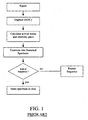
- FIG. 1 A flow diagram illustrating a known Analogue to Digital Converter ion detector system is shown in Fig. 1 .
- An input transient signal resulting from a trigger event is digitised and converted into arrival time and intensity pairs at the end of each transients predefined record length.
- a series of arrival time and intensity pairs are combined with those of other mass spectra within a predefined integration period or scan time to form a single mass spectrum.
- Each mass spectrum may comprise many tens of thousands of transients.
- a significant disadvantage of the known method is that it has a limited dynamic range and at relatively high signal intensities the Analogue to Digital Converter will suffer from saturation effects. It is also difficult to determine with any certainty whether or not the signal within an individual transient has saturated the Analogue to Digital Converter especially if the input signal changes significantly in intensity during the scan time. This frequently occurs, for example, on the leading or falling edge of an eluting LC peak. This can lead to inaccuracies in mass measurement and quantitation which are difficult to detect in the final data set.
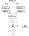
- a single transient signal output from the ion detector is preferably converted into two transient signals.
- the first transient signal is preferably emplified by or with a first voltage gain A and the second transient signal is preferably amplified by or with a second voltage gain of B.
- the first voltage gain A is preferably greater than the second voltage gain B (i.e. A > B).
- the second voltage gain B may be greater than the first voltage gain A.
- the two transient signals are then preferably digitised using two Analogue to Digital Converters.
- the lower gain (B) may be set 25 times lower.
- the two resulting digitised transients are then preferably processed to determine the arrival time (or mass or mass to charge ratio) and intensity of all detected ion arrival events.
- two lists of ion arrival times (or mass or mass to charge ratio) and corresponding intensity values are produced.
- this preferably involves an event detection step to identify regions relating to ion arrival events followed by a centroid measurement of the arrival time (or mass or mass to charge ratio) and corresponding intensity.
- Other methods of ion arrival event measurement and evaluation may be employed.
- each of the high gain transient digitised samples in the region of an ion arrival event being processed is preferably checked to see whether the Analogue to Digital Converter is suffering from saturation. For example, for an 8 bit Analogue to Digital Converter the output may be checked for values equal to 255. If the result of this check is TRUE, then the arrival time (or mass or mass to charge ratio) and corresponding intensity values for this event are preferably marked or tagged (by setting a bit associated with the registered event), The result is, in this example, two lists of events with high gain transient events that have saturated data embedded within them being tagged or flagged.
- ion arrival events which have been recorded wherein the Analogue to Digital Converter suffers from saturation are preferably identified and replaced with the corresponding event or events as recorded in the low gain transient list by scaling the intensity by the appropriate gain ratio A/B (or B/A). There may be more than one event in the low gain data which corresponds to a single saturated event in the high gain data.
- the preferred embodiment preferably results in a list of arrival time (or mass or mass to charge ratio) and intensity pairs having a higher dynamic range then either of the two original arrival time (or mass or mass to charge ratio) and intensity pair lists.
- the high dynamic range list may be combined with corresponding lists or data obtained from previous transients using a known method.
- Other less preferred methods of combining the transient signal event data may be employed.
- a histogram approach may be employed.
- detector signals may be monitored at more than one point in a dynode chain or in the case of a detector employing a dynode strip the signal may be monitored at various positions or locations along the dynode strip.
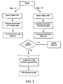
- Fig. 3 An examplary arrangement is shown in Fig. 3 .
- the signal from the ion detector is preferably split and amplified according to the method described above.
- the two transients are preferably combined to form a single high dynamic range transient.
- the high dynamic range transient is then preferably processed in order to produce a single list of events comprising arrival time (or mass or mass to charge ratio) and intensity pairs.
- the list of arrival time (or mass or mass to charge ratio) and intensity pairs is then preferably combined with other corresponding transient data as described above to form a summed spectrum.
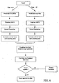
- Fig. 4 shows an embodiment of the present invention.
- the two transient data streams are preferably kept separate throughout the process and are both preferably written to disk on a scan by scan basis.
- a high dynamic range spectrum is then preferably constructed by combining the two transient data streams as a post processing operation.
- This method has the slight disadvantage that the potential of high speed parallel processing which is potentially afforded by fast Field-Programmable Gate Array (FPGA) devices is not fully utilised.
- FPGA Field-Programmable Gate Array
- Fig. 5 shows an embodiment which more fully utilises the fast processing capabilities of Field-Programmable Gate Array devices. According to this embodiment an improvement in performance relative to the embodiment described above with reference to Fig. 4 is preferably observable.
- both methods have the slight disadvantage that it may be difficult to determine at what point saturation effects occur.
- a detector signal may be processed that changes from a low ion arrival rate for the first half of an integration period or scan to a high ion arrival rate (thereby saturating the Analogue to Digital Converter) for the remainder. Examination just of the average ion arrival rate may suggest that the high gain data does not suffer from saturation effects whereas in fact the high gain data may suffer from saturation effects and will result in corrupted data.
- non-linear analogue or amplifier processing stages are preferably provided prior to digitisation.
- the gain associated with these stages may, for example, comprise an intensity dependent gain (e.g. as in a logarithmic amplifier) or an intensity switched gain.
- the gain may reduce when the input signal exceeds a given threshold value and may increase when the signal falls below a given value.
- the gain switch may be registered by a processing Field-Programmable Gate Array.
- the changes induced by the non-linear stages are preferably reversed.
- the antilog of the digitised transient may be calculated.
- the digitised transient may be multiplied or divided by an appropriate factor when the gain was determined to switch.
- a person skilled in the art may construct other advantageous non-linear analogue blocks.
- non-linear amplifiers as described above with reference to Fig. 6 may also be incorporated in the various embodiments as described above with reference to Figs. 4-5 .
- Reversing the gain changes imposed by non-linear amplification prior to combining individual transient signals has advantages over performing this operation on the final spectrum produced at the end of a scan period particularly for situations where the average ion arrival rate changes during the can period as previously described.
Landscapes
- Chemical & Material Sciences (AREA)
- Analytical Chemistry (AREA)
- Other Investigation Or Analysis Of Materials By Electrical Means (AREA)
- Electron Tubes For Measurement (AREA)
Claims (7)
- Procédé de détection d'ions consistant à:- émettre un premier signal et un second signal depuis un détecteur d'ions, ladite étape d'émission dudit premier signal et dudit second signal consistant à convertir, partager ou diviser un signal émis depuis un détecteur d'ions en ledit premier signal et ledit second signal, lequel premier signal correspond à un signal multiplié ou amplifié par un premier gain tandis que ledit second signal correspond à un signal multiplié ou amplifié par un second gain différent ; et- numériser ledit premier signal en utilisant un premier convertisseur analogique-numérique afin de produire un premier signal numérisé, et numériser ledit second signal en utilisant un second convertisseur analogique-numérique afin de produire un second signal numérisé ; caractérisé en ce qu'il consiste à :- déterminer des premières intensité et données correspondantes de temps d'arrivée, de masse ou de rapport masse-charge à partir dudit premier signal numérisé, laquelle étape de détermination desdites premières intensité et données correspondantes de temps d'arrivée, de masse ou de rapport masse-charge consiste en outre à traiter ledit premier signal numérisé afin de détecter un premier ensemble de pics et à déterminer l'intensité ainsi que les données de temps d'arrivée, de masse ou de rapport masse-charge pour chacun ou au moins certains des pics dans ledit premier ensemble de pics ;- déterminer des secondes intensité et données correspondantes de temps d'arrivée, de masse ou de rapport masse-charge à partir dudit second signal numérisé, laquelle étape de détermination desdites secondes intensité et données correspondantes de temps d'arrivée, de masse ou de rapport masse-charge consiste en outre à traiter ledit second signal numérisé afin de détecter un second ensemble de pics et à déterminer l'intensité ainsi que les données de temps d'arrivée, de masse ou de rapport masse-charge pour chacun ou au moins certains des pics dans ledit second ensemble de pics ;- additionner lesdites premières intensité et données de temps d'arrivée, de masse ou de rapport masse-charge à plusieurs autres premières intensité et données de temps d'arrivée, de masse ou de rapport masse-charge correspondantes de manière à former un premier spectre additionné ;- additionner lesdites secondes intensité et données de temps d'arrivée, de masse ou de rapport masse-charge à plusieurs autres secondes intensité et données de temps d'arrivée, de masse ou de rapport masse-charge correspondantes de manière à former un second spectre additionné ; et- combiner ledit premier spectre additionné et ledit second spectre additionné de manière à former un spectre final.
- Procédé selon la revendication 1, dans lequel :- (a) ladite étape consistant à déterminer lesdites premières intensité et données de temps d'arrivée, de masse ou de rapport masse-charge consiste en outre à marquer ou jalonner chaque pic dans ledit premier ensemble de pics lorsque l'on détermine que le signal numérisé maximal dans un pic est égal à ou se rapproche d'une sortie numérisée maximale ou pleine échelle ou qu'il est saturé ou proche de la saturation ; et- (b) ladite étape consistant à déterminer lesdites secondes intensité et données de temps d'arrivée, de masse ou de rapport masse-charge consiste en outre à marquer ou jalonner chaque pic dans ledit second ensemble de pics lorsque l'on détermine que le signal numérisé maximal dans un pic est égal à ou se rapproche d'une sortie numérisée maximale ou pleine échelle ou qu'il est saturé ou proche de la saturation.
- Procédé selon la revendication 1 ou 2, dans lequel ladite étape consistant à combiner ledit premier spectre additionné et ledit second spectre additionné de manière à former un spectre final consiste en outre à : - (a) choisir une intensité de pic et des données de temps d'arrivée, de masse ou de rapport masse-charge à partir dudit second spectre additionné pour chacun ou au moins certains des pics qui ne sont pas marqués ni jalonnés ou qui ne sont pas reportés comme étant saturés ou proches de la saturation ; et- (b) choisir une intensité de pic et des données de temps d'arrivée, de masse ou de rapport masse-charge à partir dudit premier spectre additionné lorsque le pic le plus proche ou qu'un pic proche ayant le temps d'arrivée le plus proche ou un temps d'arrivée proche dans ledit second spectre additionné est marqué ou jalonné ou est reporté comme étant saturé ou proche de la saturation,
- Procédé selon la revendication 3, consistant en outre à échelonner lesdits pics choisis à partir dudit premier spectre additionné à l'aide d'un facteur d'échelle.
- Procédé selon la revendication 4, dans lequel ledit facteur d'échelle correspond, est proche ou est autrement lié au rapport entre ledit second gain et ledit premier gain.
- Procédé selon l'une quelconque des revendications précédentes, consistant en outre à jalonner des données dans ledit premier signal numérisé et/ou ledit second signal numérisé déterminées comme correspondantes aux données obtenues lorsque le détecteur d'ions était saturé ou proche de la saturation, lequel procédé consiste en outre à ;- (a) soit remplacer une partie au moins dudit premier signal numérisé par une partie au moins dudit second signal numérisé s'il est établi que cette partie au moins dudit premier signal numérisé subit des effets de saturation ;- (b) soit remplacer une partie au moins dudit second signal numérisé par une partie au moins dudit premier signal numérisé s'il est établi que cette partie au moins dudit second signal numérisé subit des effets de saturation.
- Système de détecteur d'ions comprenant :- un dispositif conçu et adapté pour convertir, partager ou diviser une sortie de signal provenant d'un détecteur d'ions en un premier signal et un second signal, lequel premier signal correspond à un signal multiplié ou amplifié par un premier gain tandis que ledit second signal correspond à un signal multiplié ou amplifié par un second gain différent ;- un premier convertisseur analogique-numérique conçu et adapté pour numériser ledit premier signal afin de produire un premier signal numérisé, et un second convertisseur analogique-numérique conçu et adapté pour numériser ledit second signal afin de produire un second signal numérisé ;caractérisé en ce que ledit système comprend en outre :- un dispositif conçu et adapté pour déterminer des premières intensité et données correspondantes de temps d'arrivée, de masse ou de rapport masse-charge à partir dudit premier signal numérisé, laquelle étape de détermination desdites premières intensité et données correspondantes de temps d'arrivée, de masse ou de rapport masse-charge consiste à traiter ledit premier signal numérisé afin de détecter un premier ensemble de pics et à déterminer l'intensité ainsi que les données de temps d'arrivée, de masse ou de rapport masse-charge pour chacun ou au moins certains des pics dans ledit premier ensemble de pics ;- un dispositif conçu et adapté pour déterminer des secondes intensité et données correspondantes de temps d'arrivée, de masse ou de rapport masse-charge à partir dudit second signal numérisé, laquelle étape de détermination desdites secondes intensité et données correspondantes de temps d'arrivée, de masse ou de rapport masse-charge consiste à traiter ledit second signal numérisé afin de détecter un second ensemble de pics et à déterminer l'intensité ainsi que les données de temps d'arrivée, de masse ou de rapport masse-charge pour chacun ou au moins certains des pics dans ledit second ensemble de pics ;- un dispositif conçu et adapté pour additionner lesdites premières intensité et données de temps d'arrivée, de masse ou de rapport masse-charge à plusieurs autres premières intensité et données de temps d'arrivée, de masse ou de rapport masse-charge correspondantes de manière à former un premier spectre additionné ;- un dispositif conçu et adapté pour additionner lesdites secondes intensité et données de temps d'arrivée, de masse ou de rapport masse-charge à plusieurs autres secondes intensité et données de temps d'arrivée, de masse ou de rapport masse-charge correspondantes de manière à former un second spectre additionné ; et- un dispositif conçu et adapté pour combiner ledit premier spectre additionné et ledit second spectre additionné de manière à former un spectre final.
Applications Claiming Priority (3)
| Application Number | Priority Date | Filing Date | Title |
|---|---|---|---|
| GB0709799A GB0709799D0 (en) | 2007-05-22 | 2007-05-22 | Mass spectrometer |
| US94621107P | 2007-06-26 | 2007-06-26 | |
| EP08750679A EP2156460B1 (fr) | 2007-05-22 | 2008-05-22 | Spectromètre de masse |
Related Parent Applications (1)
| Application Number | Title | Priority Date | Filing Date |
|---|---|---|---|
| EP08750679.6 Division | 2008-05-22 |
Publications (3)
| Publication Number | Publication Date |
|---|---|
| EP2184763A2 EP2184763A2 (fr) | 2010-05-12 |
| EP2184763A3 EP2184763A3 (fr) | 2010-07-07 |
| EP2184763B1 true EP2184763B1 (fr) | 2012-07-18 |
Family
ID=38234872
Family Applications (3)
| Application Number | Title | Priority Date | Filing Date |
|---|---|---|---|
| EP10000200A Active EP2184763B1 (fr) | 2007-05-22 | 2008-05-22 | Spectromètre de masse |
| EP11194978A Withdrawn EP2434526A1 (fr) | 2007-05-22 | 2008-05-22 | Spectromètre de masse |
| EP08750679A Active EP2156460B1 (fr) | 2007-05-22 | 2008-05-22 | Spectromètre de masse |
Family Applications After (2)
| Application Number | Title | Priority Date | Filing Date |
|---|---|---|---|
| EP11194978A Withdrawn EP2434526A1 (fr) | 2007-05-22 | 2008-05-22 | Spectromètre de masse |
| EP08750679A Active EP2156460B1 (fr) | 2007-05-22 | 2008-05-22 | Spectromètre de masse |
Country Status (6)
| Country | Link |
|---|---|
| US (3) | US8354634B2 (fr) |
| EP (3) | EP2184763B1 (fr) |
| JP (1) | JP5528331B2 (fr) |
| CA (1) | CA2687420C (fr) |
| GB (2) | GB0709799D0 (fr) |
| WO (1) | WO2008142418A2 (fr) |
Families Citing this family (42)
| Publication number | Priority date | Publication date | Assignee | Title |
|---|---|---|---|---|
| GB0709799D0 (en) * | 2007-05-22 | 2007-06-27 | Micromass Ltd | Mass spectrometer |
| GB0909289D0 (en) * | 2009-05-29 | 2009-07-15 | Micromass Ltd | Method of processing mass spectral data |
| IT1395787B1 (it) * | 2009-09-16 | 2012-10-19 | Dani Instr Spa | Spettrometro di massa ad ampio intervallo di dinamica. |
| US9330892B2 (en) | 2009-12-31 | 2016-05-03 | Spectro Analytical Instruments Gmbh | Simultaneous inorganic mass spectrometer and method of inorganic mass spectrometry |
| DE102010056152A1 (de) * | 2009-12-31 | 2011-07-07 | Spectro Analytical Instruments GmbH, 47533 | Simultanes anorganisches Massenspektrometer und Verfahren zur anorganischen Massenspektrometrie |
| JP5781545B2 (ja) * | 2010-02-02 | 2015-09-24 | ディーエイチ テクノロジーズ デベロップメント プライベート リミテッド | 飛行時間型質量分析検出システムを操作する方法およびシステム |
| GB201002447D0 (en) | 2010-02-12 | 2010-03-31 | Micromass Ltd | Mass spectrometer |
| DE102010011974B4 (de) | 2010-03-19 | 2016-09-15 | Bruker Daltonik Gmbh | Sättigungskorrektur für Ionensignale in Flugzeitmassenspektrometern |
| CN103270575B (zh) | 2010-12-17 | 2016-10-26 | 塞莫费雪科学(不来梅)有限公司 | 用于质谱法的数据采集系统和方法 |
| GB201106689D0 (en) * | 2011-04-20 | 2011-06-01 | Micromass Ltd | Function switching with fast asynchronous acquisition |
| CN103582929B (zh) * | 2011-06-03 | 2016-10-19 | Dh科技发展私人贸易有限公司 | 使用可变窗口带通过滤从测量扫描移除离子以改善扫描内动态范围 |
| GB201208841D0 (en) * | 2012-05-18 | 2012-07-04 | Micromass Ltd | Calibrating dual adc acquisition system |
| US10354849B2 (en) * | 2013-07-09 | 2019-07-16 | Micromass Uk Limited | Method of recording ADC saturation |
| GB201312266D0 (en) * | 2013-07-09 | 2013-08-21 | Micromass Ltd | Method of recording ADC saturation |
| WO2015004457A1 (fr) * | 2013-07-09 | 2015-01-15 | Micromass Uk Limited | Amélioration de plage dynamique intelligente |
| US9899200B2 (en) * | 2014-05-13 | 2018-02-20 | Micromass Uk Limited | Multi-dimensional ion separation |
| GB201410382D0 (en) * | 2014-06-11 | 2014-07-23 | Micromass Ltd | Flagging ADC coalescence |
| DE112015002758T5 (de) | 2014-06-11 | 2017-04-20 | Micromass Uk Limited | Markieren von ADC-Koaleszenz |
| GB201514643D0 (en) * | 2015-08-18 | 2015-09-30 | Micromass Ltd | Mass Spectrometer data acquisition |
| GB201515357D0 (en) | 2015-08-28 | 2015-10-14 | Micromass Ltd | Mass spectrometer with digitial step attenuator |
| GB2544959B (en) * | 2015-09-17 | 2019-06-05 | Thermo Fisher Scient Bremen Gmbh | Mass spectrometer |
| US10026598B2 (en) * | 2016-01-04 | 2018-07-17 | Rohde & Schwarz Gmbh & Co. Kg | Signal amplitude measurement and calibration with an ion trap |
| CN105609401B (zh) * | 2016-02-17 | 2017-10-24 | 广州禾信分析仪器有限公司 | 一种提高飞行时间质谱仪器动态检测范围的方法及系统 |
| US20170263426A1 (en) * | 2016-03-10 | 2017-09-14 | Leco Corporation | Dynamic Baseline Adjuster |
| GB201613988D0 (en) | 2016-08-16 | 2016-09-28 | Micromass Uk Ltd And Leco Corp | Mass analyser having extended flight path |
| GB201618023D0 (en) * | 2016-10-25 | 2016-12-07 | Micromass Uk Limited | Ion detection system |
| GB2567794B (en) | 2017-05-05 | 2023-03-08 | Micromass Ltd | Multi-reflecting time-of-flight mass spectrometers |
| GB2563571B (en) | 2017-05-26 | 2023-05-24 | Micromass Ltd | Time of flight mass analyser with spatial focussing |
| US11239067B2 (en) | 2017-08-06 | 2022-02-01 | Micromass Uk Limited | Ion mirror for multi-reflecting mass spectrometers |
| WO2019030471A1 (fr) | 2017-08-06 | 2019-02-14 | Anatoly Verenchikov | Guide d'ions à l'intérieur de convertisseurs pulsés |
| US11049712B2 (en) | 2017-08-06 | 2021-06-29 | Micromass Uk Limited | Fields for multi-reflecting TOF MS |
| WO2019030476A1 (fr) | 2017-08-06 | 2019-02-14 | Anatoly Verenchikov | Injection d'ions dans des spectromètres de masse à passages multiples |
| US11211238B2 (en) | 2017-08-06 | 2021-12-28 | Micromass Uk Limited | Multi-pass mass spectrometer |
| US11817303B2 (en) | 2017-08-06 | 2023-11-14 | Micromass Uk Limited | Accelerator for multi-pass mass spectrometers |
| EP3662502A1 (fr) | 2017-08-06 | 2020-06-10 | Micromass UK Limited | Miroir ionique à circuit imprimé avec compensation |
| GB201806507D0 (en) | 2018-04-20 | 2018-06-06 | Verenchikov Anatoly | Gridless ion mirrors with smooth fields |
| GB201807605D0 (en) | 2018-05-10 | 2018-06-27 | Micromass Ltd | Multi-reflecting time of flight mass analyser |
| GB201807626D0 (en) | 2018-05-10 | 2018-06-27 | Micromass Ltd | Multi-reflecting time of flight mass analyser |
| GB201808530D0 (en) | 2018-05-24 | 2018-07-11 | Verenchikov Anatoly | TOF MS detection system with improved dynamic range |
| GB201810573D0 (en) | 2018-06-28 | 2018-08-15 | Verenchikov Anatoly | Multi-pass mass spectrometer with improved duty cycle |
| GB201901411D0 (en) | 2019-02-01 | 2019-03-20 | Micromass Ltd | Electrode assembly for mass spectrometer |
| GB202110412D0 (en) * | 2021-07-20 | 2021-09-01 | Micromass Ltd | Mass spectrometer for generating and summing mass spectral data |
Citations (3)
| Publication number | Priority date | Publication date | Assignee | Title |
|---|---|---|---|---|
| US4490806A (en) * | 1982-06-04 | 1984-12-25 | Research Corporation | High repetition rate transient recorder with automatic integration |
| US20040084613A1 (en) * | 2001-04-03 | 2004-05-06 | Bateman Robert Harold | Mass spectrometer and method of mass spectrometry |
| WO2006129094A2 (fr) * | 2005-06-03 | 2006-12-07 | Micromass Uk Limited | Spectrometre de masse |
Family Cites Families (14)
| Publication number | Priority date | Publication date | Assignee | Title |
|---|---|---|---|---|
| JPS5760654A (en) | 1980-09-26 | 1982-04-12 | Jeol Ltd | Spectral detecting method |
| JPS61207962A (ja) | 1985-03-12 | 1986-09-16 | Jeol Ltd | 質量分析計の質量較正方法 |
| JPH09184823A (ja) * | 1995-12-28 | 1997-07-15 | Shimadzu Corp | 分析装置の検出信号処理装置 |
| ATE319855T1 (de) | 1996-12-10 | 2006-03-15 | Sequenom Inc | Abspaltbare, nicht-flüchtige moleküle zur massenmarkierung |
| US6259101B1 (en) * | 1997-09-23 | 2001-07-10 | University Of Delaware | Method and instruments for the on-line detection, sizing or analysis of aerosol particles |
| US6195031B1 (en) | 1998-12-28 | 2001-02-27 | Siemens Aktiengesellschaft | Analog-to-digital converter with level converter and level recognition unit and correction memory |
| GB9920711D0 (en) * | 1999-09-03 | 1999-11-03 | Hd Technologies Limited | High dynamic range mass spectrometer |
| EP1405055A4 (fr) * | 2001-05-25 | 2007-05-23 | Analytica Of Branford Inc | Systeme de detectton multiples |
| DE10206173B4 (de) | 2002-02-14 | 2006-08-31 | Bruker Daltonik Gmbh | Hochauflösende Detektion für Flugzeitmassenspektrometer |
| CA2571206A1 (fr) | 2004-07-01 | 2006-01-19 | Ciphergen Biosystems, Inc. | Amplificateurs de signaux non lineaires et utilisations de ces amplificateurs dans un dispositif spectrometre de masse |
| US7238936B2 (en) * | 2004-07-02 | 2007-07-03 | Thermo Finnigan Llc | Detector with increased dynamic range |
| US7423259B2 (en) * | 2006-04-27 | 2008-09-09 | Agilent Technologies, Inc. | Mass spectrometer and method for enhancing dynamic range |
| US7501621B2 (en) | 2006-07-12 | 2009-03-10 | Leco Corporation | Data acquisition system for a spectrometer using an adaptive threshold |
| GB0709799D0 (en) * | 2007-05-22 | 2007-06-27 | Micromass Ltd | Mass spectrometer |
-
2007
- 2007-05-22 GB GB0709799A patent/GB0709799D0/en not_active Ceased
-
2008
- 2008-05-22 CA CA2687420A patent/CA2687420C/fr not_active Expired - Fee Related
- 2008-05-22 EP EP10000200A patent/EP2184763B1/fr active Active
- 2008-05-22 GB GB0809338.7A patent/GB2457112C/en active Active
- 2008-05-22 EP EP11194978A patent/EP2434526A1/fr not_active Withdrawn
- 2008-05-22 US US12/601,094 patent/US8354634B2/en active Active
- 2008-05-22 WO PCT/GB2008/001756 patent/WO2008142418A2/fr active Application Filing
- 2008-05-22 JP JP2010508903A patent/JP5528331B2/ja active Active
- 2008-05-22 EP EP08750679A patent/EP2156460B1/fr active Active
-
2013
- 2013-01-10 US US13/738,507 patent/US8754364B2/en active Active
-
2014
- 2014-05-06 US US14/270,433 patent/US8941056B2/en active Active
Patent Citations (3)
| Publication number | Priority date | Publication date | Assignee | Title |
|---|---|---|---|---|
| US4490806A (en) * | 1982-06-04 | 1984-12-25 | Research Corporation | High repetition rate transient recorder with automatic integration |
| US20040084613A1 (en) * | 2001-04-03 | 2004-05-06 | Bateman Robert Harold | Mass spectrometer and method of mass spectrometry |
| WO2006129094A2 (fr) * | 2005-06-03 | 2006-12-07 | Micromass Uk Limited | Spectrometre de masse |
Also Published As
| Publication number | Publication date |
|---|---|
| JP2010528280A (ja) | 2010-08-19 |
| WO2008142418A2 (fr) | 2008-11-27 |
| EP2156460B1 (fr) | 2013-01-30 |
| US20140326867A1 (en) | 2014-11-06 |
| EP2184763A2 (fr) | 2010-05-12 |
| US8754364B2 (en) | 2014-06-17 |
| EP2434526A1 (fr) | 2012-03-28 |
| GB0709799D0 (en) | 2007-06-27 |
| EP2156460A2 (fr) | 2010-02-24 |
| EP2184763A3 (fr) | 2010-07-07 |
| US20100213361A1 (en) | 2010-08-26 |
| US8354634B2 (en) | 2013-01-15 |
| GB2457112B (en) | 2010-02-03 |
| US8941056B2 (en) | 2015-01-27 |
| US20130119247A1 (en) | 2013-05-16 |
| WO2008142418A3 (fr) | 2009-11-05 |
| CA2687420A1 (fr) | 2008-11-27 |
| GB0809338D0 (en) | 2008-07-02 |
| GB2457112A (en) | 2009-08-05 |
| CA2687420C (fr) | 2016-09-13 |
| JP5528331B2 (ja) | 2014-06-25 |
| GB2457112C (en) | 2016-02-03 |
Similar Documents
| Publication | Publication Date | Title |
|---|---|---|
| EP2184763B1 (fr) | Spectromètre de masse | |
| US9053911B2 (en) | Method of processing mass spectral data | |
| US8598513B2 (en) | Mass spectrometer | |
| US8809767B2 (en) | Time of flight mass spectrometer with analog to digital converter and method of using | |
| US9673031B2 (en) | Conversion of ion arrival times or ion intensities into multiple intensities or arrival times in a mass spectrometer | |
| GB2429110A (en) | Determining the arrival times of ions at an ion detector |
Legal Events
| Date | Code | Title | Description |
|---|---|---|---|
| PUAI | Public reference made under article 153(3) epc to a published international application that has entered the european phase |
Free format text: ORIGINAL CODE: 0009012 |
|
| AC | Divisional application: reference to earlier application |
Ref document number: 2156460 Country of ref document: EP Kind code of ref document: P |
|
| AK | Designated contracting states |
Kind code of ref document: A2 Designated state(s): AT BE BG CH CY CZ DE DK EE ES FI FR GB GR HR HU IE IS IT LI LT LU LV MC MT NL NO PL PT RO SE SI SK TR |
|
| AX | Request for extension of the european patent |
Extension state: AL BA MK RS |
|
| PUAL | Search report despatched |
Free format text: ORIGINAL CODE: 0009013 |
|
| AK | Designated contracting states |
Kind code of ref document: A3 Designated state(s): AT BE BG CH CY CZ DE DK EE ES FI FR GB GR HR HU IE IS IT LI LT LU LV MC MT NL NO PL PT RO SE SI SK TR |
|
| AX | Request for extension of the european patent |
Extension state: AL BA MK RS |
|
| 17P | Request for examination filed |
Effective date: 20110107 |
|
| GRAP | Despatch of communication of intention to grant a patent |
Free format text: ORIGINAL CODE: EPIDOSNIGR1 |
|
| GRAS | Grant fee paid |
Free format text: ORIGINAL CODE: EPIDOSNIGR3 |
|
| GRAA | (expected) grant |
Free format text: ORIGINAL CODE: 0009210 |
|
| AC | Divisional application: reference to earlier application |
Ref document number: 2156460 Country of ref document: EP Kind code of ref document: P |
|
| AK | Designated contracting states |
Kind code of ref document: B1 Designated state(s): AT BE BG CH CY CZ DE DK EE ES FI FR GB GR HR HU IE IS IT LI LT LU LV MC MT NL NO PL PT RO SE SI SK TR |
|
| REG | Reference to a national code |
Ref country code: GB Ref legal event code: FG4D |
|
| REG | Reference to a national code |
Ref country code: CH Ref legal event code: EP |
|
| REG | Reference to a national code |
Ref country code: AT Ref legal event code: REF Ref document number: 567203 Country of ref document: AT Kind code of ref document: T Effective date: 20120815 Ref country code: IE Ref legal event code: FG4D |
|
| REG | Reference to a national code |
Ref country code: DE Ref legal event code: R096 Ref document number: 602008017326 Country of ref document: DE Effective date: 20120913 |
|
| REG | Reference to a national code |
Ref country code: NL Ref legal event code: VDEP Effective date: 20120718 |
|
| REG | Reference to a national code |
Ref country code: AT Ref legal event code: MK05 Ref document number: 567203 Country of ref document: AT Kind code of ref document: T Effective date: 20120718 |
|
| REG | Reference to a national code |
Ref country code: LT Ref legal event code: MG4D Effective date: 20120711 |
|
| PG25 | Lapsed in a contracting state [announced via postgrant information from national office to epo] |
Ref country code: CY Free format text: LAPSE BECAUSE OF FAILURE TO SUBMIT A TRANSLATION OF THE DESCRIPTION OR TO PAY THE FEE WITHIN THE PRESCRIBED TIME-LIMIT Effective date: 20120718 Ref country code: HR Free format text: LAPSE BECAUSE OF FAILURE TO SUBMIT A TRANSLATION OF THE DESCRIPTION OR TO PAY THE FEE WITHIN THE PRESCRIBED TIME-LIMIT Effective date: 20120718 Ref country code: FI Free format text: LAPSE BECAUSE OF FAILURE TO SUBMIT A TRANSLATION OF THE DESCRIPTION OR TO PAY THE FEE WITHIN THE PRESCRIBED TIME-LIMIT Effective date: 20120718 Ref country code: IS Free format text: LAPSE BECAUSE OF FAILURE TO SUBMIT A TRANSLATION OF THE DESCRIPTION OR TO PAY THE FEE WITHIN THE PRESCRIBED TIME-LIMIT Effective date: 20121118 Ref country code: BE Free format text: LAPSE BECAUSE OF FAILURE TO SUBMIT A TRANSLATION OF THE DESCRIPTION OR TO PAY THE FEE WITHIN THE PRESCRIBED TIME-LIMIT Effective date: 20120718 Ref country code: LT Free format text: LAPSE BECAUSE OF FAILURE TO SUBMIT A TRANSLATION OF THE DESCRIPTION OR TO PAY THE FEE WITHIN THE PRESCRIBED TIME-LIMIT Effective date: 20120718 Ref country code: NO Free format text: LAPSE BECAUSE OF FAILURE TO SUBMIT A TRANSLATION OF THE DESCRIPTION OR TO PAY THE FEE WITHIN THE PRESCRIBED TIME-LIMIT Effective date: 20121018 Ref country code: AT Free format text: LAPSE BECAUSE OF FAILURE TO SUBMIT A TRANSLATION OF THE DESCRIPTION OR TO PAY THE FEE WITHIN THE PRESCRIBED TIME-LIMIT Effective date: 20120718 |
|
| PG25 | Lapsed in a contracting state [announced via postgrant information from national office to epo] |
Ref country code: SI Free format text: LAPSE BECAUSE OF FAILURE TO SUBMIT A TRANSLATION OF THE DESCRIPTION OR TO PAY THE FEE WITHIN THE PRESCRIBED TIME-LIMIT Effective date: 20120718 Ref country code: LV Free format text: LAPSE BECAUSE OF FAILURE TO SUBMIT A TRANSLATION OF THE DESCRIPTION OR TO PAY THE FEE WITHIN THE PRESCRIBED TIME-LIMIT Effective date: 20120718 Ref country code: PL Free format text: LAPSE BECAUSE OF FAILURE TO SUBMIT A TRANSLATION OF THE DESCRIPTION OR TO PAY THE FEE WITHIN THE PRESCRIBED TIME-LIMIT Effective date: 20120718 Ref country code: SE Free format text: LAPSE BECAUSE OF FAILURE TO SUBMIT A TRANSLATION OF THE DESCRIPTION OR TO PAY THE FEE WITHIN THE PRESCRIBED TIME-LIMIT Effective date: 20120718 Ref country code: GR Free format text: LAPSE BECAUSE OF FAILURE TO SUBMIT A TRANSLATION OF THE DESCRIPTION OR TO PAY THE FEE WITHIN THE PRESCRIBED TIME-LIMIT Effective date: 20121019 Ref country code: PT Free format text: LAPSE BECAUSE OF FAILURE TO SUBMIT A TRANSLATION OF THE DESCRIPTION OR TO PAY THE FEE WITHIN THE PRESCRIBED TIME-LIMIT Effective date: 20121119 |
|
| PG25 | Lapsed in a contracting state [announced via postgrant information from national office to epo] |
Ref country code: NL Free format text: LAPSE BECAUSE OF FAILURE TO SUBMIT A TRANSLATION OF THE DESCRIPTION OR TO PAY THE FEE WITHIN THE PRESCRIBED TIME-LIMIT Effective date: 20120718 |
|
| PG25 | Lapsed in a contracting state [announced via postgrant information from national office to epo] |
Ref country code: RO Free format text: LAPSE BECAUSE OF FAILURE TO SUBMIT A TRANSLATION OF THE DESCRIPTION OR TO PAY THE FEE WITHIN THE PRESCRIBED TIME-LIMIT Effective date: 20120718 Ref country code: EE Free format text: LAPSE BECAUSE OF FAILURE TO SUBMIT A TRANSLATION OF THE DESCRIPTION OR TO PAY THE FEE WITHIN THE PRESCRIBED TIME-LIMIT Effective date: 20120718 Ref country code: CZ Free format text: LAPSE BECAUSE OF FAILURE TO SUBMIT A TRANSLATION OF THE DESCRIPTION OR TO PAY THE FEE WITHIN THE PRESCRIBED TIME-LIMIT Effective date: 20120718 Ref country code: ES Free format text: LAPSE BECAUSE OF FAILURE TO SUBMIT A TRANSLATION OF THE DESCRIPTION OR TO PAY THE FEE WITHIN THE PRESCRIBED TIME-LIMIT Effective date: 20121029 Ref country code: DK Free format text: LAPSE BECAUSE OF FAILURE TO SUBMIT A TRANSLATION OF THE DESCRIPTION OR TO PAY THE FEE WITHIN THE PRESCRIBED TIME-LIMIT Effective date: 20120718 |
|
| PLBE | No opposition filed within time limit |
Free format text: ORIGINAL CODE: 0009261 |
|
| STAA | Information on the status of an ep patent application or granted ep patent |
Free format text: STATUS: NO OPPOSITION FILED WITHIN TIME LIMIT |
|
| PG25 | Lapsed in a contracting state [announced via postgrant information from national office to epo] |
Ref country code: IT Free format text: LAPSE BECAUSE OF FAILURE TO SUBMIT A TRANSLATION OF THE DESCRIPTION OR TO PAY THE FEE WITHIN THE PRESCRIBED TIME-LIMIT Effective date: 20120718 Ref country code: SK Free format text: LAPSE BECAUSE OF FAILURE TO SUBMIT A TRANSLATION OF THE DESCRIPTION OR TO PAY THE FEE WITHIN THE PRESCRIBED TIME-LIMIT Effective date: 20120718 |
|
| 26N | No opposition filed |
Effective date: 20130419 |
|
| PG25 | Lapsed in a contracting state [announced via postgrant information from national office to epo] |
Ref country code: BG Free format text: LAPSE BECAUSE OF FAILURE TO SUBMIT A TRANSLATION OF THE DESCRIPTION OR TO PAY THE FEE WITHIN THE PRESCRIBED TIME-LIMIT Effective date: 20121018 |
|
| REG | Reference to a national code |
Ref country code: DE Ref legal event code: R097 Ref document number: 602008017326 Country of ref document: DE Effective date: 20130419 |
|
| PG25 | Lapsed in a contracting state [announced via postgrant information from national office to epo] |
Ref country code: MC Free format text: LAPSE BECAUSE OF FAILURE TO SUBMIT A TRANSLATION OF THE DESCRIPTION OR TO PAY THE FEE WITHIN THE PRESCRIBED TIME-LIMIT Effective date: 20120718 |
|
| REG | Reference to a national code |
Ref country code: CH Ref legal event code: PL |
|
| PG25 | Lapsed in a contracting state [announced via postgrant information from national office to epo] |
Ref country code: CH Free format text: LAPSE BECAUSE OF NON-PAYMENT OF DUE FEES Effective date: 20130531 Ref country code: LI Free format text: LAPSE BECAUSE OF NON-PAYMENT OF DUE FEES Effective date: 20130531 |
|
| REG | Reference to a national code |
Ref country code: IE Ref legal event code: MM4A |
|
| PG25 | Lapsed in a contracting state [announced via postgrant information from national office to epo] |
Ref country code: IE Free format text: LAPSE BECAUSE OF NON-PAYMENT OF DUE FEES Effective date: 20130522 |
|
| PG25 | Lapsed in a contracting state [announced via postgrant information from national office to epo] |
Ref country code: MT Free format text: LAPSE BECAUSE OF FAILURE TO SUBMIT A TRANSLATION OF THE DESCRIPTION OR TO PAY THE FEE WITHIN THE PRESCRIBED TIME-LIMIT Effective date: 20120718 |
|
| PG25 | Lapsed in a contracting state [announced via postgrant information from national office to epo] |
Ref country code: TR Free format text: LAPSE BECAUSE OF FAILURE TO SUBMIT A TRANSLATION OF THE DESCRIPTION OR TO PAY THE FEE WITHIN THE PRESCRIBED TIME-LIMIT Effective date: 20120718 |
|
| PG25 | Lapsed in a contracting state [announced via postgrant information from national office to epo] |
Ref country code: HU Free format text: LAPSE BECAUSE OF FAILURE TO SUBMIT A TRANSLATION OF THE DESCRIPTION OR TO PAY THE FEE WITHIN THE PRESCRIBED TIME-LIMIT; INVALID AB INITIO Effective date: 20080522 Ref country code: LU Free format text: LAPSE BECAUSE OF NON-PAYMENT OF DUE FEES Effective date: 20130522 |
|
| REG | Reference to a national code |
Ref country code: FR Ref legal event code: PLFP Year of fee payment: 9 |
|
| REG | Reference to a national code |
Ref country code: FR Ref legal event code: PLFP Year of fee payment: 10 |
|
| REG | Reference to a national code |
Ref country code: FR Ref legal event code: PLFP Year of fee payment: 11 |
|
| PGFP | Annual fee paid to national office [announced via postgrant information from national office to epo] |
Ref country code: FR Payment date: 20180423 Year of fee payment: 11 |
|
| PG25 | Lapsed in a contracting state [announced via postgrant information from national office to epo] |
Ref country code: FR Free format text: LAPSE BECAUSE OF NON-PAYMENT OF DUE FEES Effective date: 20190531 |
|
| REG | Reference to a national code |
Ref country code: DE Ref legal event code: R082 Ref document number: 602008017326 Country of ref document: DE |
|
| P01 | Opt-out of the competence of the unified patent court (upc) registered |
Effective date: 20230506 |
|
| PGFP | Annual fee paid to national office [announced via postgrant information from national office to epo] |
Ref country code: DE Payment date: 20230419 Year of fee payment: 16 |
|
| PGFP | Annual fee paid to national office [announced via postgrant information from national office to epo] |
Ref country code: GB Payment date: 20230420 Year of fee payment: 16 |