EP2184455B1 - Structure de montage d'injecteur - Google Patents
Structure de montage d'injecteur Download PDFInfo
- Publication number
- EP2184455B1 EP2184455B1 EP08720508.4A EP08720508A EP2184455B1 EP 2184455 B1 EP2184455 B1 EP 2184455B1 EP 08720508 A EP08720508 A EP 08720508A EP 2184455 B1 EP2184455 B1 EP 2184455B1
- Authority
- EP
- European Patent Office
- Prior art keywords
- injector
- exhaust gas
- adapter
- urea water
- side end
- Prior art date
- Legal status (The legal status is an assumption and is not a legal conclusion. Google has not performed a legal analysis and makes no representation as to the accuracy of the status listed.)
- Not-in-force
Links
- WTHDKMILWLGDKL-UHFFFAOYSA-N urea;hydrate Chemical compound O.NC(N)=O WTHDKMILWLGDKL-UHFFFAOYSA-N 0.000 claims description 25
- 239000007789 gas Substances 0.000 description 50
- 239000003054 catalyst Substances 0.000 description 25
- QGZKDVFQNNGYKY-UHFFFAOYSA-N Ammonia Chemical compound N QGZKDVFQNNGYKY-UHFFFAOYSA-N 0.000 description 16
- 229910021529 ammonia Inorganic materials 0.000 description 8
- 238000007254 oxidation reaction Methods 0.000 description 7
- CURLTUGMZLYLDI-UHFFFAOYSA-N Carbon dioxide Chemical compound O=C=O CURLTUGMZLYLDI-UHFFFAOYSA-N 0.000 description 4
- 238000010276 construction Methods 0.000 description 4
- 239000000446 fuel Substances 0.000 description 4
- 230000003647 oxidation Effects 0.000 description 4
- 238000011144 upstream manufacturing Methods 0.000 description 3
- QVGXLLKOCUKJST-UHFFFAOYSA-N atomic oxygen Chemical compound [O] QVGXLLKOCUKJST-UHFFFAOYSA-N 0.000 description 2
- 229910002092 carbon dioxide Inorganic materials 0.000 description 2
- 239000001569 carbon dioxide Substances 0.000 description 2
- 239000003638 chemical reducing agent Substances 0.000 description 2
- 230000000694 effects Effects 0.000 description 2
- 239000001301 oxygen Substances 0.000 description 2
- 229910052760 oxygen Inorganic materials 0.000 description 2
- 230000035484 reaction time Effects 0.000 description 2
- 230000008929 regeneration Effects 0.000 description 2
- 238000011069 regeneration method Methods 0.000 description 2
- 238000006243 chemical reaction Methods 0.000 description 1
- 239000006185 dispersion Substances 0.000 description 1
- 239000000284 extract Substances 0.000 description 1
- 239000011491 glass wool Substances 0.000 description 1
- 238000002347 injection Methods 0.000 description 1
- 239000007924 injection Substances 0.000 description 1
- 239000011810 insulating material Substances 0.000 description 1
- 239000012212 insulator Substances 0.000 description 1
- 238000004519 manufacturing process Methods 0.000 description 1
- 239000002245 particle Substances 0.000 description 1
- 238000005192 partition Methods 0.000 description 1
- 230000002093 peripheral effect Effects 0.000 description 1
- 238000000197 pyrolysis Methods 0.000 description 1
- 239000000243 solution Substances 0.000 description 1
- 230000001629 suppression Effects 0.000 description 1
- 238000003466 welding Methods 0.000 description 1
Images


Classifications
-
- F—MECHANICAL ENGINEERING; LIGHTING; HEATING; WEAPONS; BLASTING
- F01—MACHINES OR ENGINES IN GENERAL; ENGINE PLANTS IN GENERAL; STEAM ENGINES
- F01N—GAS-FLOW SILENCERS OR EXHAUST APPARATUS FOR MACHINES OR ENGINES IN GENERAL; GAS-FLOW SILENCERS OR EXHAUST APPARATUS FOR INTERNAL COMBUSTION ENGINES
- F01N3/00—Exhaust or silencing apparatus having means for purifying, rendering innocuous, or otherwise treating exhaust
- F01N3/08—Exhaust or silencing apparatus having means for purifying, rendering innocuous, or otherwise treating exhaust for rendering innocuous
- F01N3/10—Exhaust or silencing apparatus having means for purifying, rendering innocuous, or otherwise treating exhaust for rendering innocuous by thermal or catalytic conversion of noxious components of exhaust
- F01N3/18—Exhaust or silencing apparatus having means for purifying, rendering innocuous, or otherwise treating exhaust for rendering innocuous by thermal or catalytic conversion of noxious components of exhaust characterised by methods of operation; Control
- F01N3/20—Exhaust or silencing apparatus having means for purifying, rendering innocuous, or otherwise treating exhaust for rendering innocuous by thermal or catalytic conversion of noxious components of exhaust characterised by methods of operation; Control specially adapted for catalytic conversion ; Methods of operation or control of catalytic converters
- F01N3/2066—Selective catalytic reduction [SCR]
-
- F—MECHANICAL ENGINEERING; LIGHTING; HEATING; WEAPONS; BLASTING
- F01—MACHINES OR ENGINES IN GENERAL; ENGINE PLANTS IN GENERAL; STEAM ENGINES
- F01N—GAS-FLOW SILENCERS OR EXHAUST APPARATUS FOR MACHINES OR ENGINES IN GENERAL; GAS-FLOW SILENCERS OR EXHAUST APPARATUS FOR INTERNAL COMBUSTION ENGINES
- F01N13/00—Exhaust or silencing apparatus characterised by constructional features ; Exhaust or silencing apparatus, or parts thereof, having pertinent characteristics not provided for in, or of interest apart from, groups F01N1/00 - F01N5/00, F01N9/00, F01N11/00
- F01N13/009—Exhaust or silencing apparatus characterised by constructional features ; Exhaust or silencing apparatus, or parts thereof, having pertinent characteristics not provided for in, or of interest apart from, groups F01N1/00 - F01N5/00, F01N9/00, F01N11/00 having two or more separate purifying devices arranged in series
-
- F—MECHANICAL ENGINEERING; LIGHTING; HEATING; WEAPONS; BLASTING
- F01—MACHINES OR ENGINES IN GENERAL; ENGINE PLANTS IN GENERAL; STEAM ENGINES
- F01N—GAS-FLOW SILENCERS OR EXHAUST APPARATUS FOR MACHINES OR ENGINES IN GENERAL; GAS-FLOW SILENCERS OR EXHAUST APPARATUS FOR INTERNAL COMBUSTION ENGINES
- F01N13/00—Exhaust or silencing apparatus characterised by constructional features ; Exhaust or silencing apparatus, or parts thereof, having pertinent characteristics not provided for in, or of interest apart from, groups F01N1/00 - F01N5/00, F01N9/00, F01N11/00
- F01N13/14—Exhaust or silencing apparatus characterised by constructional features ; Exhaust or silencing apparatus, or parts thereof, having pertinent characteristics not provided for in, or of interest apart from, groups F01N1/00 - F01N5/00, F01N9/00, F01N11/00 having thermal insulation
-
- F—MECHANICAL ENGINEERING; LIGHTING; HEATING; WEAPONS; BLASTING
- F01—MACHINES OR ENGINES IN GENERAL; ENGINE PLANTS IN GENERAL; STEAM ENGINES
- F01N—GAS-FLOW SILENCERS OR EXHAUST APPARATUS FOR MACHINES OR ENGINES IN GENERAL; GAS-FLOW SILENCERS OR EXHAUST APPARATUS FOR INTERNAL COMBUSTION ENGINES
- F01N3/00—Exhaust or silencing apparatus having means for purifying, rendering innocuous, or otherwise treating exhaust
- F01N3/02—Exhaust or silencing apparatus having means for purifying, rendering innocuous, or otherwise treating exhaust for cooling, or for removing solid constituents of, exhaust
- F01N3/021—Exhaust or silencing apparatus having means for purifying, rendering innocuous, or otherwise treating exhaust for cooling, or for removing solid constituents of, exhaust by means of filters
- F01N3/033—Exhaust or silencing apparatus having means for purifying, rendering innocuous, or otherwise treating exhaust for cooling, or for removing solid constituents of, exhaust by means of filters in combination with other devices
- F01N3/035—Exhaust or silencing apparatus having means for purifying, rendering innocuous, or otherwise treating exhaust for cooling, or for removing solid constituents of, exhaust by means of filters in combination with other devices with catalytic reactors, e.g. catalysed diesel particulate filters
-
- F—MECHANICAL ENGINEERING; LIGHTING; HEATING; WEAPONS; BLASTING
- F01—MACHINES OR ENGINES IN GENERAL; ENGINE PLANTS IN GENERAL; STEAM ENGINES
- F01N—GAS-FLOW SILENCERS OR EXHAUST APPARATUS FOR MACHINES OR ENGINES IN GENERAL; GAS-FLOW SILENCERS OR EXHAUST APPARATUS FOR INTERNAL COMBUSTION ENGINES
- F01N2250/00—Combinations of different methods of purification
- F01N2250/02—Combinations of different methods of purification filtering and catalytic conversion
-
- F—MECHANICAL ENGINEERING; LIGHTING; HEATING; WEAPONS; BLASTING
- F01—MACHINES OR ENGINES IN GENERAL; ENGINE PLANTS IN GENERAL; STEAM ENGINES
- F01N—GAS-FLOW SILENCERS OR EXHAUST APPARATUS FOR MACHINES OR ENGINES IN GENERAL; GAS-FLOW SILENCERS OR EXHAUST APPARATUS FOR INTERNAL COMBUSTION ENGINES
- F01N2260/00—Exhaust treating devices having provisions not otherwise provided for
- F01N2260/20—Exhaust treating devices having provisions not otherwise provided for for heat or sound protection, e.g. using a shield or specially shaped outer surface of exhaust device
-
- F—MECHANICAL ENGINEERING; LIGHTING; HEATING; WEAPONS; BLASTING
- F01—MACHINES OR ENGINES IN GENERAL; ENGINE PLANTS IN GENERAL; STEAM ENGINES
- F01N—GAS-FLOW SILENCERS OR EXHAUST APPARATUS FOR MACHINES OR ENGINES IN GENERAL; GAS-FLOW SILENCERS OR EXHAUST APPARATUS FOR INTERNAL COMBUSTION ENGINES
- F01N2610/00—Adding substances to exhaust gases
- F01N2610/02—Adding substances to exhaust gases the substance being ammonia or urea
-
- F—MECHANICAL ENGINEERING; LIGHTING; HEATING; WEAPONS; BLASTING
- F01—MACHINES OR ENGINES IN GENERAL; ENGINE PLANTS IN GENERAL; STEAM ENGINES
- F01N—GAS-FLOW SILENCERS OR EXHAUST APPARATUS FOR MACHINES OR ENGINES IN GENERAL; GAS-FLOW SILENCERS OR EXHAUST APPARATUS FOR INTERNAL COMBUSTION ENGINES
- F01N2610/00—Adding substances to exhaust gases
- F01N2610/14—Arrangements for the supply of substances, e.g. conduits
- F01N2610/1453—Sprayers or atomisers; Arrangement thereof in the exhaust apparatus
-
- Y—GENERAL TAGGING OF NEW TECHNOLOGICAL DEVELOPMENTS; GENERAL TAGGING OF CROSS-SECTIONAL TECHNOLOGIES SPANNING OVER SEVERAL SECTIONS OF THE IPC; TECHNICAL SUBJECTS COVERED BY FORMER USPC CROSS-REFERENCE ART COLLECTIONS [XRACs] AND DIGESTS
- Y02—TECHNOLOGIES OR APPLICATIONS FOR MITIGATION OR ADAPTATION AGAINST CLIMATE CHANGE
- Y02A—TECHNOLOGIES FOR ADAPTATION TO CLIMATE CHANGE
- Y02A50/00—TECHNOLOGIES FOR ADAPTATION TO CLIMATE CHANGE in human health protection, e.g. against extreme weather
- Y02A50/20—Air quality improvement or preservation, e.g. vehicle emission control or emission reduction by using catalytic converters
-
- Y—GENERAL TAGGING OF NEW TECHNOLOGICAL DEVELOPMENTS; GENERAL TAGGING OF CROSS-SECTIONAL TECHNOLOGIES SPANNING OVER SEVERAL SECTIONS OF THE IPC; TECHNICAL SUBJECTS COVERED BY FORMER USPC CROSS-REFERENCE ART COLLECTIONS [XRACs] AND DIGESTS
- Y02—TECHNOLOGIES OR APPLICATIONS FOR MITIGATION OR ADAPTATION AGAINST CLIMATE CHANGE
- Y02T—CLIMATE CHANGE MITIGATION TECHNOLOGIES RELATED TO TRANSPORTATION
- Y02T10/00—Road transport of goods or passengers
- Y02T10/10—Internal combustion engine [ICE] based vehicles
- Y02T10/12—Improving ICE efficiencies
Definitions
- the present invention relates to an injector mounting structure for an injector which adds urea water as reducing agent so as to reduce and depurate NO x upstream of a selective reduction catalyst.
- a particulate filter for capturing particulates in exhaust gas is incorporated in an exhaust pipe and a selective reduction catalyst capable of selectively reacting NO x with ammonia even in the presence of oxygen is arranged downstream of the particulate filter, urea water as reducing agent being added between the selective reduction catalyst and the particulate filter, thereby attaining reduction of both the particulates and NO x .
- Such addition of the urea water to the selective reduction catalyst is conducted between the particulate filter and the selective reduction catalyst.
- it is necessary to prolong a distance between a urea water added position and the selective reduction catalyst.
- such arrangement of the particulate filter and the selective reduction catalyst substantially spaced apart from each other will extremely impair the mountability on a vehicle.
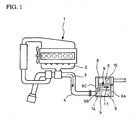
- a compact exhaust emission control device as shown in Figs. 1 and 2 has been proposed by the inventor as Japanese patent application No. 2007-29923 .
- a particulate filter 5 housed in a casing 7 to capture particles in the exhaust gas 3; arranged downstream of and in parallel with the particulate filter 5 and housed in a casing 8 is a selective reduction catalyst 6 having a property capable of selectively reacting NO x with ammonia even in the presence of oxygen.
- An exit-side end of the particulate filter 5 is connected to an entry-side end of the selective reduction catalyst 6 through an S-shaped communication passage 9 such that the exhaust gas 3 discharged through the exit-side end of the particulate filter 5 is reversely curved back into the entry-side end of the adjacent selective reduction catalyst 6.
- the communication passage 9 is the S-shaped structure comprising a gas gathering chamber 9A which encircles the exit-side end of the particulate filter 5 to gather the exhaust gas 3 through substantially perpendicular turnabout of the gas just discharged from the exit-side end of the particulate filter 5, a mixing pipe 9B which extracts the gathered exhaust gas 3 from the chamber 9A in a direction reverse to that of the exhaust gas flow in the filter 5 and which is provided with an injector 11 for urea water addition (urea water addition means) intermediately of the mixing pipe and a gas dispersing chamber 9C which encircles the entry-side end of the selective reduction catalyst 6 so as to disperse the gas 3 guided by the mixing pipe 9B through substantially perpendicular turnabout into the entry-side end of the selective reduction catalyst 6.
- a gas gathering chamber 9A which encircles the exit-side end of the particulate filter 5 to gather the exhaust gas 3 through substantially perpendicular turnabout of the gas just discharged from the exit-side end of the particulate filter 5,
- an oxidation catalyst 14 for oxidization treatment of unburned fuel in the exhaust gas 3.
- an ammonia reducing catalyst 15 for oxidization treatment of surplus ammonia.
- particulates in the exhaust gas 3 are captured by the particulate filter 5.
- the urea water is added intermediately of the mixing pipe 9B and downstream of the filter into the exhaust gas 3 by the injector 11 and is pyrolyzed into ammonia and carbon dioxide gas, so that NO x in the exhaust gas 3 is satisfactorily reduced and depurated by the ammonia on the selective reduction catalyst 6. As a result, both the particulates and NO x in the exhaust gas 3 are reduced.
- the exhaust gas 3 discharged from the exit-side end of the particulate filter 5 is reversely curved back by the communication passage 9 into the entry-side end of the adjacent selective reduction catalyst 6.
- enough reaction time is ensured for production of ammonia from the urea water since a long distance between the urea water added position intermediately of the communication passage 9 and the selective reduction catalyst 6 is ensured and the flow of the exhaust gas 3 becomes turbulent due to the reversed curving to facilitate mixing of the urea water with the exhaust gas 3.
- the particulate filter 5 and selective reduction catalyst 6 are arranged in parallel with each other and the communication passage 9 is arranged between and along the particulate filter 5 and selective reduction catalyst 6, so that the whole structure becomes compact in size to substantially improve its mountability on a vehicle.
- urea water to the selective reduction catalyst 6 at between the particulate filter 5 and the selective reduction catalyst 6 is conducted in such a manner that a boss 10 is provided intermediately of and branched obliquely from the mixing pipe 9B to be directed upstream, the injector 11 for addition of urea water being fitted into the boss 10 from outside of the mixing pipe 9B, urea water being added with the injector 11 being protected so as not to be directly exposed to the flow of the hot exhaust gas 3.
- the energetic flow of the exhaust gas 3 may urge the urea water added through the injector 11 to be biased against and along an inner wall of the mixing pipe 9B, resulting in failure of satisfactorily dispersion of the urea water.
- a downstream end 9a of the gas gathering chamber 9A is changed in its connection with the entry-side end of the mixing pipe 9B to surround the latter in a properly spaced manner with an open edge of the entry-side end being closed.
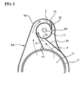
- the entry-side end of the mixing pipe 9B is formed with first and second openings 12 and 13 and is provided with first, second and third partitions 16, 17 and 18, so that the exhaust gas 3 from the particulate filter 5 swirls in one direction around the entry-side end of the mixing pipe 9B and guided tangentially into the same through the first and second openings 12 and 13; the injector 11 is fitted at and axially of the entry-side end of the mixing pipe 9B for addition of the urea water by the injector 11 axially of the entry-side end of the mixing pipe 9B (this application has been filed and allotted Japanese patent application No. 2007-56963 ).
- swirling flow is effectively formed in the mixing pipe B by inflow of the exhaust gas 3 through the first and second openings 12 and 13; the urea water is added by the injector 11 axially into the entry-side end of the mixing pipe 9B where the swirling flow is most energetic, so that the added urea water is satisfactorily dispersed into the exhaust gas 3 by the swirling flow to substantially enhance the mixing with the exhaust gas 3.
- Patent Literature 1 As a prior art literature pertinent to the invention, there exists, for example, the following Patent Literature 1.
- the opening edge of the entry-side end of the mixing pipe 9B is closed by an adapter to which the injector 11 is bolted.
- the adapter is directly exposed to the flow of the exhaust gas 3 and has increased thermal load, which may impair reliability of the injector 11 due to overheat.
- regeneration of the filter 5 is attained in such a manner that fuel is added to the exhaust gas 3 by the diesel engine 1 through, for example, post injection, the added fuel (HC) undergoing oxidation reaction on the upstream-side oxidation catalyst 14, the exhaust temperature being elevated by the reaction heat to increase the catalyst floor temperature of the particulate filter 5 to thereby burn out any captured particulates.
- HC added fuel
- An injector for injecting fuel is known from document EP 1 662 108 .
- the injector is mounted to the exhaust gas passage via an adapter flange.
- the adapter flange is mounted on the exhaust gas passage via a thermal insulator.
- the invention was made in view of the above and has its object to suppress heat transfer from an adapter to an injector so as to make it possible to favorably ensure the reliability of the injector for a long time.
- the invention is directed to an injector mounting structure, the injector being incorporated in an exhaust passage through an adapter so as to add urea water to exhaust gas, characterized in that an inner surface of said adapter to be exposed to the exhaust gas flow is shielded by a heat-resisting plate to interpose a heat insulating layer between said plate and said inner surface.
- the inner surface of the adapter to be exposed to the flow of the exhaust gas is shielded by the heat-resisting plate and heat transfer from the adapter to the injector is significantly suppressed by the heat insulating layer interposed between the plate and the inner surface of the adapter, so that the injector is prevented from being damaged due to overheat.
- parts for fastening the adapter and the injector together are air-tightly shielded by the plate, which brings about suppression of heat transfer to the fastening parts for the adapter and injector and which also causes the plate to serve as gas seal for the fastening parts.
- An injector mounting structure according to the invention as mentioned in the above can bring about various meritorious effects as mentioned in the below.
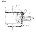
- FIG. 6 shows the embodiment of the invention which has a structure substantially similar to that shown in Figs. 4 and 5 , a downstream end 9a of a gas gathering chamber 9A being connected to an entry-side end of a mixing pipe 9B (exhaust passage), an injector 11 for urea water addition being fitted axially of the entry-side end of the mixing pipe 9B.
- a disc-like adapter 19 is fitted into the opening edge of the entry-side end of the mixing pipe 9B, so that the opening edge of the entry-side end of the mixing pipe 9B is closed by the adapter 19.
- the injector 11 is fastened to an outer surface of the adapter 19 by means of a stud bolt 20 and a nut 21 (fastening parts).
- thermoelectric plate 22 An inner surface of the adapter 19 to be exposed to the exhaust gas 3 is shielded by a heat-resisting plate 22 so that a space only including air is interposed between the plate 22 and the inner surface as heat insulating layer 23 (alternatively, heat-insulating material such as glass wool may be charged into the heat insulating layer 23).
- the adapter 19 is axially formed with a lead-in opening 24 which guides urea water injected through the injector 11 into the mixing pipe 9B, a portion of the inner surface of the adapter 19 surrounding the lead-in opening 24 is raised to provide a step against its periphery, the step being utilized to provide a heat insulating layer 23 between the plate 22 and the inner surface of the adapter 19.
- An outer periphery of the plate 22 extends over an outer periphery of the adapter 19 to an outer side surface of the adapter 19 where it is fixed in welding to the entry-side end of the mixing pipe 9B throughout the periphery so as to keep air-tightness.
- the inner surface of the adapter 19 to be exposed to the flow of the exhaust gas 3 is shielded by the heat-resisting plate 22 and moreover heat transfer from the adapter 19 to the injector 11 is significantly suppressed by the heat insulating layer 23 interposed between the plate 22 and the inner surface of the adapter 19, so that the injector 11 is prevented from being damaged due to overheat.
- the fastening parts in the form of the stud bolt 20 and nut 21 for the adapter 19 and injector 11 are air-tightly shielded by the plate 22, so that heat transfer to the fastening parts for the adapter 19 and injector 11 is also suppressed and moreover the plate 22 also serves as gas seal for the fastening parts.
- the inner surface of the adapter 19 to be exposed to the flow of the exhaust gas 3 is shielded by the heat-resisting plate 22 and the heat insulating layer 23 is interposed between the plate 22 and the inner surface, so that heat transfer from the adapter 19 to the injector 11 can be significantly suppressed and the injector 11 can be prevented from being damaged due to overheat, so that reliability of the injector 11 can be satisfactorily ensured for a long time.
- the fastening parts in the form of the stud bolt 20 and nut 21 for the adapter 19 and injector 11 can be suppressed and the plate 22 can also serve as gas seal for the fastening parts, so that the fastening parts are protected against heat of the exhaust gas 3 and corrosive components.
- the stud bolt 20 and nut 21 can be prevented from being damaged due to seizure, high-temperature oxidation and the like.
- the invention is not always limited to the connection of particulate filter and selective reduction catalyst arranged in parallel with each other through the S-shaped communication passage.
- the urea water added position and its peripheral construction are not limited to those in the embodiment illustrated.
- the fastening parts are not always a combination of stud bolt and nut.
Landscapes
- Engineering & Computer Science (AREA)
- Chemical & Material Sciences (AREA)
- Combustion & Propulsion (AREA)
- Mechanical Engineering (AREA)
- General Engineering & Computer Science (AREA)
- Chemical Kinetics & Catalysis (AREA)
- Health & Medical Sciences (AREA)
- Toxicology (AREA)
- Exhaust Gas After Treatment (AREA)
- Processes For Solid Components From Exhaust (AREA)
Claims (1)
- Structure de montage d'injecteur (11), l'injecteur (11) étant incorporé dans un passage de gaz d'échappement par le biais d'un adaptateur (19), moyennant quoi une surface interne dudit adaptateur (19) à exposer à l'écoulement de gaz d'échappement (3) est protégée par une plaque résistant à la chaleur (22) en intercalant une couche d'isolation thermique (23) entre ladite plaque (22) et ladite surface interne, caractérisée en ce que l'injecteur est adapté pour ajouter une solution d'urée-eau au gaz d'échappement (3) et en ce que les pièces pour fixer l'adaptateur (19) et l'injecteur (11) ensemble sont protégées de manière étanche à l'air par la plaque (22).
Applications Claiming Priority (2)
| Application Number | Priority Date | Filing Date | Title |
|---|---|---|---|
| JP2007228641A JP4886636B2 (ja) | 2007-09-04 | 2007-09-04 | インジェクタの取付構造 |
| PCT/JP2008/000623 WO2009031252A1 (fr) | 2007-09-04 | 2008-03-18 | Structure de montage d'injecteur |
Publications (3)
| Publication Number | Publication Date |
|---|---|
| EP2184455A1 EP2184455A1 (fr) | 2010-05-12 |
| EP2184455A4 EP2184455A4 (fr) | 2011-06-22 |
| EP2184455B1 true EP2184455B1 (fr) | 2013-06-19 |
Family
ID=40428576
Family Applications (1)
| Application Number | Title | Priority Date | Filing Date |
|---|---|---|---|
| EP08720508.4A Not-in-force EP2184455B1 (fr) | 2007-09-04 | 2008-03-18 | Structure de montage d'injecteur |
Country Status (5)
| Country | Link |
|---|---|
| US (1) | US8402752B2 (fr) |
| EP (1) | EP2184455B1 (fr) |
| JP (1) | JP4886636B2 (fr) |
| CN (2) | CN101796274B (fr) |
| WO (1) | WO2009031252A1 (fr) |
Families Citing this family (27)
| Publication number | Priority date | Publication date | Assignee | Title |
|---|---|---|---|---|
| DE202008001547U1 (de) | 2007-07-24 | 2008-04-10 | Emcon Technologies Germany (Augsburg) Gmbh | Baugruppe zur Einbringung eines Reduktionsmittels in die Abgasleitung einer Abgasanlage einer Verbrennungskraftmaschine |
| GB0908690D0 (en) * | 2009-05-20 | 2009-07-01 | Delphi Tech Inc | Mounting system for an exhaust system |
| DE102009027181A1 (de) * | 2009-06-25 | 2010-12-30 | Robert Bosch Gmbh | Dichteinheit |
| BR112013025571A2 (pt) * | 2011-04-04 | 2016-12-27 | Mack Trucks | injetor refrigerado por fluido e sistema de pós-tratamento de exaustão, veículo e método utilizando um injetor refrigerado por fluido |
| JP5349575B2 (ja) | 2011-12-27 | 2013-11-20 | 株式会社小松製作所 | 還元剤水溶液ミキシング装置及び排気ガス後処理装置 |
| US8916100B2 (en) | 2011-12-27 | 2014-12-23 | Komatsu Ltd. | Reducing agent aqueous solution mixing device and exhaust gas post-treatment device |
| US8932530B2 (en) | 2011-12-27 | 2015-01-13 | Komatsu Ltd. | Reducing agent aqueous solution mixing device and exhaust gas post-treatment device |
| US9133601B2 (en) * | 2012-10-16 | 2015-09-15 | Komatsu Ltd. | Hydraulic excavator |
| KR101360161B1 (ko) | 2013-01-17 | 2014-02-12 | 가부시키가이샤 고마쓰 세이사쿠쇼 | 환원제 수용액 믹싱 장치 및 이것을 구비한 배기 가스 후처리 장치 |
| WO2014112073A1 (fr) | 2013-01-17 | 2014-07-24 | 株式会社小松製作所 | Dispositif de mélange de solution aqueuse d'agent réducteur ainsi que dispositif de post-traitement de gaz d'échappement mettant en oeuvre ce dispositif de mélange |
| US8893481B2 (en) | 2013-01-17 | 2014-11-25 | Komatsu Ltd. | Reductant aqueous solution mixing device and exhaust aftertreatment device provided with the same |
| KR20140102122A (ko) | 2013-01-17 | 2014-08-21 | 가부시키가이샤 고마쓰 세이사쿠쇼 | 환원제 수용액 믹싱 장치 및 이것을 구비한 배기 가스 후처리 장치 |
| CA2900801C (fr) | 2013-02-15 | 2021-01-26 | Donaldson Company, Inc. | Agencement de dosage et de melange destine a etre utilise dans le traitement postcombustion des gaz d'echappement |
| EP3152419B1 (fr) | 2014-06-03 | 2020-03-04 | Faurecia Emissions Control Technologies, USA, LLC | Agencement de doseur cônique |
| DE102015002974A1 (de) * | 2015-03-10 | 2016-09-15 | Man Truck & Bus Ag | Vorrichtung zur Nachbehandlung von Abgas eines Kraftfahrzeugs |
| US9719397B2 (en) | 2015-04-30 | 2017-08-01 | Faurecia Emissions Control Technologies Usa, Llc | Mixer with integrated doser cone |
| WO2016176076A1 (fr) | 2015-04-30 | 2016-11-03 | Faurecia Emissions Control Technologies, Usa, Llc | Mélangeur à rotation complète |
| US9714598B2 (en) | 2015-04-30 | 2017-07-25 | Faurecia Emissions Control Technologies, Usa, Llc | Mixer with integrated doser cone |
| US9534525B2 (en) | 2015-05-27 | 2017-01-03 | Tenneco Automotive Operating Company Inc. | Mixer assembly for exhaust aftertreatment system |
| SE539834C2 (en) * | 2016-04-11 | 2017-12-12 | Scania Cv Ab | An injection arrangement for injection of a urea solution into an exhaust gas passage |
| CN106014560B (zh) * | 2016-06-01 | 2019-07-23 | 佛吉亚排气控制技术开发(上海)有限公司 | 用于混合排气和处理流体的混合器及车辆排气后处理装置 |
| JP2017218916A (ja) * | 2016-06-03 | 2017-12-14 | 日野自動車株式会社 | ミキシング構造 |
| WO2018075061A1 (fr) | 2016-10-21 | 2018-04-26 | Faurecia Emissions Control Technologies Usa, Llc | Mélangeur d'agent réducteur |
| DE102018103368A1 (de) | 2018-02-15 | 2019-08-22 | Man Truck & Bus Ag | Vorrichtung zum Mischen von Abgas und einem Additiv |
| US10787946B2 (en) | 2018-09-19 | 2020-09-29 | Faurecia Emissions Control Technologies, Usa, Llc | Heated dosing mixer |
| MX2021001593A (es) * | 2018-09-30 | 2021-05-12 | Weichai Power Co Ltd | Conjunto de montaje de boquilla y sistema de postratamiento. |
| US11286828B1 (en) * | 2020-09-25 | 2022-03-29 | Dinex A/S | Diesel exhaust treatment apparatus and methods |
Family Cites Families (16)
| Publication number | Priority date | Publication date | Assignee | Title |
|---|---|---|---|---|
| US354890A (en) * | 1886-12-28 | dickeeman | ||
| US355210A (en) * | 1886-12-28 | Spinning-machine | ||
| US356759A (en) * | 1887-02-01 | Paul gmehlikt | ||
| GB759524A (en) | 1952-12-30 | 1956-10-17 | Emmerich Satzger | An improved fuel injection nozzle for fuel injection internal combustion engines |
| JPS59115860A (ja) * | 1982-12-23 | 1984-07-04 | Konishiroku Photo Ind Co Ltd | インクジエツト記録装置 |
| JPS59115860U (ja) * | 1983-01-25 | 1984-08-04 | いすゞ自動車株式会社 | 副室式デイ−ゼルエンジンにおけるノズルヒ−トシ−ルド |
| DE19806265C5 (de) | 1998-02-16 | 2004-07-22 | Siemens Ag | Dosiersystem |
| DE19856366C1 (de) * | 1998-12-07 | 2000-04-20 | Siemens Ag | Vorrichtung und Verfahren zum Nachbehandeln von Abgasen einer mit Luftüberschuß arbeitenden Brennkraftmaschine |
| JP3532430B2 (ja) * | 1998-12-10 | 2004-05-31 | 三菱電機株式会社 | 燃料噴射弁 |
| GB0113226D0 (en) * | 2001-06-01 | 2001-07-25 | Nelson Burgess Ltd | Catalytic converter |
| GB2381218B (en) * | 2001-10-25 | 2004-12-15 | Eminox Ltd | Gas treatment apparatus |
| DE10332114A1 (de) * | 2003-07-09 | 2005-01-27 | Robert Bosch Gmbh | Gekühlte Vorrichtung zur Dosierung von Reduktionsmittel zum Abgas eines Verbrennungsmotors |
| JP2005127318A (ja) * | 2003-09-19 | 2005-05-19 | Nissan Diesel Motor Co Ltd | エンジンの排気浄化装置 |
| JP2005155404A (ja) | 2003-11-25 | 2005-06-16 | Komatsu Ltd | 内燃機関の排気ガス浄化装置 |
| DE102004056791B4 (de) | 2004-11-24 | 2007-04-19 | J. Eberspächer GmbH & Co. KG | Abgasanlage |
| EP2538048B1 (fr) * | 2007-03-30 | 2015-03-04 | Continental Automotive Systems US, Inc. | Unité de distribution d'agent réducteur pour réduction catalytique sélective |
-
2007
- 2007-09-04 JP JP2007228641A patent/JP4886636B2/ja active Active
-
2008
- 2008-03-18 EP EP08720508.4A patent/EP2184455B1/fr not_active Not-in-force
- 2008-03-18 CN CN2008801056878A patent/CN101796274B/zh active Active
- 2008-03-18 WO PCT/JP2008/000623 patent/WO2009031252A1/fr active Application Filing
- 2008-03-18 US US12/676,056 patent/US8402752B2/en active Active
- 2008-03-18 CN CN2010102339534A patent/CN101892890B/zh active Active
Also Published As
| Publication number | Publication date |
|---|---|
| EP2184455A4 (fr) | 2011-06-22 |
| JP2009062816A (ja) | 2009-03-26 |
| EP2184455A1 (fr) | 2010-05-12 |
| US20100186393A1 (en) | 2010-07-29 |
| JP4886636B2 (ja) | 2012-02-29 |
| CN101892890A (zh) | 2010-11-24 |
| US8402752B2 (en) | 2013-03-26 |
| CN101796274B (zh) | 2013-12-04 |
| WO2009031252A1 (fr) | 2009-03-12 |
| CN101892890B (zh) | 2012-12-26 |
| CN101796274A (zh) | 2010-08-04 |
Similar Documents
| Publication | Publication Date | Title |
|---|---|---|
| EP2184455B1 (fr) | Structure de montage d'injecteur | |
| US8245504B2 (en) | Exhaust emission control device | |
| US8353152B2 (en) | Exhaust emission control device | |
| EP2119885B1 (fr) | Dispositif de controle d'émission d'échappement | |
| EP2841727B1 (fr) | Module de post-traitement doté d'un agencement de montage de capteur | |
| US8377383B2 (en) | Exhaust emission control device | |
| CN101821486B (zh) | 用于对稀燃发动机的排气进行后处理的系统 | |
| EP3102801B1 (fr) | Structure de systeme des gaz d'echappement pour des moteurs a combustion interne | |
| US8813481B2 (en) | Exhaust emission control device | |
| US20140196442A1 (en) | Reductant aqueous solution mixing device and exhaust aftertreatment device provided with the same | |
| US20110225969A1 (en) | Compressor bypass to exhaust for particulate trap regeneration | |
| EP3364006A1 (fr) | Dispositif de purification des gaz d'échappement | |
| JP2009091983A (ja) | 排気浄化装置 | |
| US9816427B2 (en) | Catalytic converter device for a stationary internal combustion engine | |
| JP2020041528A (ja) | 排気ガス浄化システム | |
| EP3358158B1 (fr) | Dispositif de purification de gaz d'échappement | |
| CN115875119A (zh) | 用于内燃机的排气设备 | |
| CN112752898A (zh) | 喷嘴安装组件及后处理系统 |
Legal Events
| Date | Code | Title | Description |
|---|---|---|---|
| PUAI | Public reference made under article 153(3) epc to a published international application that has entered the european phase |
Free format text: ORIGINAL CODE: 0009012 |
|
| 17P | Request for examination filed |
Effective date: 20100225 |
|
| AK | Designated contracting states |
Kind code of ref document: A1 Designated state(s): AT BE BG CH CY CZ DE DK EE ES FI FR GB GR HR HU IE IS IT LI LT LU LV MC MT NL NO PL PT RO SE SI SK TR |
|
| AX | Request for extension of the european patent |
Extension state: AL BA MK RS |
|
| DAX | Request for extension of the european patent (deleted) | ||
| REG | Reference to a national code |
Ref country code: DE Ref legal event code: R079 Ref document number: 602008025419 Country of ref document: DE Free format text: PREVIOUS MAIN CLASS: F01N0003080000 Ipc: F01N0003200000 |
|
| A4 | Supplementary search report drawn up and despatched |
Effective date: 20110524 |
|
| RIC1 | Information provided on ipc code assigned before grant |
Ipc: F01N 3/20 20060101AFI20110518BHEP |
|
| REG | Reference to a national code |
Ref country code: DE Ref legal event code: R079 Ref document number: 602008025419 Country of ref document: DE Free format text: PREVIOUS MAIN CLASS: F01N0003200000 Ipc: F01N0003035000 |
|
| RIC1 | Information provided on ipc code assigned before grant |
Ipc: F01N 13/14 20100101ALI20121128BHEP Ipc: F01N 3/20 20060101ALI20121128BHEP Ipc: F01N 3/035 20060101AFI20121128BHEP |
|
| GRAP | Despatch of communication of intention to grant a patent |
Free format text: ORIGINAL CODE: EPIDOSNIGR1 |
|
| GRAS | Grant fee paid |
Free format text: ORIGINAL CODE: EPIDOSNIGR3 |
|
| GRAA | (expected) grant |
Free format text: ORIGINAL CODE: 0009210 |
|
| AK | Designated contracting states |
Kind code of ref document: B1 Designated state(s): AT BE BG CH CY CZ DE DK EE ES FI FR GB GR HR HU IE IS IT LI LT LU LV MC MT NL NO PL PT RO SE SI SK TR |
|
| REG | Reference to a national code |
Ref country code: GB Ref legal event code: FG4D |
|
| REG | Reference to a national code |
Ref country code: CH Ref legal event code: EP |
|
| REG | Reference to a national code |
Ref country code: AT Ref legal event code: REF Ref document number: 617782 Country of ref document: AT Kind code of ref document: T Effective date: 20130715 |
|
| REG | Reference to a national code |
Ref country code: IE Ref legal event code: FG4D |
|
| REG | Reference to a national code |
Ref country code: DE Ref legal event code: R096 Ref document number: 602008025419 Country of ref document: DE Effective date: 20130814 |
|
| PG25 | Lapsed in a contracting state [announced via postgrant information from national office to epo] |
Ref country code: SI Free format text: LAPSE BECAUSE OF FAILURE TO SUBMIT A TRANSLATION OF THE DESCRIPTION OR TO PAY THE FEE WITHIN THE PRESCRIBED TIME-LIMIT Effective date: 20130619 Ref country code: NO Free format text: LAPSE BECAUSE OF FAILURE TO SUBMIT A TRANSLATION OF THE DESCRIPTION OR TO PAY THE FEE WITHIN THE PRESCRIBED TIME-LIMIT Effective date: 20130919 Ref country code: FI Free format text: LAPSE BECAUSE OF FAILURE TO SUBMIT A TRANSLATION OF THE DESCRIPTION OR TO PAY THE FEE WITHIN THE PRESCRIBED TIME-LIMIT Effective date: 20130619 Ref country code: LT Free format text: LAPSE BECAUSE OF FAILURE TO SUBMIT A TRANSLATION OF THE DESCRIPTION OR TO PAY THE FEE WITHIN THE PRESCRIBED TIME-LIMIT Effective date: 20130619 Ref country code: GR Free format text: LAPSE BECAUSE OF FAILURE TO SUBMIT A TRANSLATION OF THE DESCRIPTION OR TO PAY THE FEE WITHIN THE PRESCRIBED TIME-LIMIT Effective date: 20130920 Ref country code: SE Free format text: LAPSE BECAUSE OF FAILURE TO SUBMIT A TRANSLATION OF THE DESCRIPTION OR TO PAY THE FEE WITHIN THE PRESCRIBED TIME-LIMIT Effective date: 20130619 Ref country code: ES Free format text: LAPSE BECAUSE OF FAILURE TO SUBMIT A TRANSLATION OF THE DESCRIPTION OR TO PAY THE FEE WITHIN THE PRESCRIBED TIME-LIMIT Effective date: 20130930 |
|
| REG | Reference to a national code |
Ref country code: AT Ref legal event code: MK05 Ref document number: 617782 Country of ref document: AT Kind code of ref document: T Effective date: 20130619 |
|
| REG | Reference to a national code |
Ref country code: LT Ref legal event code: MG4D |
|
| PG25 | Lapsed in a contracting state [announced via postgrant information from national office to epo] |
Ref country code: BG Free format text: LAPSE BECAUSE OF FAILURE TO SUBMIT A TRANSLATION OF THE DESCRIPTION OR TO PAY THE FEE WITHIN THE PRESCRIBED TIME-LIMIT Effective date: 20130919 Ref country code: HR Free format text: LAPSE BECAUSE OF FAILURE TO SUBMIT A TRANSLATION OF THE DESCRIPTION OR TO PAY THE FEE WITHIN THE PRESCRIBED TIME-LIMIT Effective date: 20130619 |
|
| REG | Reference to a national code |
Ref country code: NL Ref legal event code: VDEP Effective date: 20130619 |
|
| PG25 | Lapsed in a contracting state [announced via postgrant information from national office to epo] |
Ref country code: LV Free format text: LAPSE BECAUSE OF FAILURE TO SUBMIT A TRANSLATION OF THE DESCRIPTION OR TO PAY THE FEE WITHIN THE PRESCRIBED TIME-LIMIT Effective date: 20130619 |
|
| PG25 | Lapsed in a contracting state [announced via postgrant information from national office to epo] |
Ref country code: PT Free format text: LAPSE BECAUSE OF FAILURE TO SUBMIT A TRANSLATION OF THE DESCRIPTION OR TO PAY THE FEE WITHIN THE PRESCRIBED TIME-LIMIT Effective date: 20131021 Ref country code: IS Free format text: LAPSE BECAUSE OF FAILURE TO SUBMIT A TRANSLATION OF THE DESCRIPTION OR TO PAY THE FEE WITHIN THE PRESCRIBED TIME-LIMIT Effective date: 20131019 Ref country code: EE Free format text: LAPSE BECAUSE OF FAILURE TO SUBMIT A TRANSLATION OF THE DESCRIPTION OR TO PAY THE FEE WITHIN THE PRESCRIBED TIME-LIMIT Effective date: 20130619 Ref country code: CY Free format text: LAPSE BECAUSE OF FAILURE TO SUBMIT A TRANSLATION OF THE DESCRIPTION OR TO PAY THE FEE WITHIN THE PRESCRIBED TIME-LIMIT Effective date: 20130828 Ref country code: BE Free format text: LAPSE BECAUSE OF FAILURE TO SUBMIT A TRANSLATION OF THE DESCRIPTION OR TO PAY THE FEE WITHIN THE PRESCRIBED TIME-LIMIT Effective date: 20130619 Ref country code: SK Free format text: LAPSE BECAUSE OF FAILURE TO SUBMIT A TRANSLATION OF THE DESCRIPTION OR TO PAY THE FEE WITHIN THE PRESCRIBED TIME-LIMIT Effective date: 20130619 Ref country code: CZ Free format text: LAPSE BECAUSE OF FAILURE TO SUBMIT A TRANSLATION OF THE DESCRIPTION OR TO PAY THE FEE WITHIN THE PRESCRIBED TIME-LIMIT Effective date: 20130619 Ref country code: AT Free format text: LAPSE BECAUSE OF FAILURE TO SUBMIT A TRANSLATION OF THE DESCRIPTION OR TO PAY THE FEE WITHIN THE PRESCRIBED TIME-LIMIT Effective date: 20130619 |
|
| PG25 | Lapsed in a contracting state [announced via postgrant information from national office to epo] |
Ref country code: PL Free format text: LAPSE BECAUSE OF FAILURE TO SUBMIT A TRANSLATION OF THE DESCRIPTION OR TO PAY THE FEE WITHIN THE PRESCRIBED TIME-LIMIT Effective date: 20130619 Ref country code: NL Free format text: LAPSE BECAUSE OF FAILURE TO SUBMIT A TRANSLATION OF THE DESCRIPTION OR TO PAY THE FEE WITHIN THE PRESCRIBED TIME-LIMIT Effective date: 20130619 Ref country code: RO Free format text: LAPSE BECAUSE OF FAILURE TO SUBMIT A TRANSLATION OF THE DESCRIPTION OR TO PAY THE FEE WITHIN THE PRESCRIBED TIME-LIMIT Effective date: 20130619 |
|
| PG25 | Lapsed in a contracting state [announced via postgrant information from national office to epo] |
Ref country code: CY Free format text: LAPSE BECAUSE OF FAILURE TO SUBMIT A TRANSLATION OF THE DESCRIPTION OR TO PAY THE FEE WITHIN THE PRESCRIBED TIME-LIMIT Effective date: 20130619 |
|
| PLBE | No opposition filed within time limit |
Free format text: ORIGINAL CODE: 0009261 |
|
| STAA | Information on the status of an ep patent application or granted ep patent |
Free format text: STATUS: NO OPPOSITION FILED WITHIN TIME LIMIT |
|
| PG25 | Lapsed in a contracting state [announced via postgrant information from national office to epo] |
Ref country code: DK Free format text: LAPSE BECAUSE OF FAILURE TO SUBMIT A TRANSLATION OF THE DESCRIPTION OR TO PAY THE FEE WITHIN THE PRESCRIBED TIME-LIMIT Effective date: 20130619 |
|
| 26N | No opposition filed |
Effective date: 20140320 |
|
| PG25 | Lapsed in a contracting state [announced via postgrant information from national office to epo] |
Ref country code: IT Free format text: LAPSE BECAUSE OF FAILURE TO SUBMIT A TRANSLATION OF THE DESCRIPTION OR TO PAY THE FEE WITHIN THE PRESCRIBED TIME-LIMIT Effective date: 20130619 |
|
| REG | Reference to a national code |
Ref country code: DE Ref legal event code: R097 Ref document number: 602008025419 Country of ref document: DE Effective date: 20140320 |
|
| PG25 | Lapsed in a contracting state [announced via postgrant information from national office to epo] |
Ref country code: LU Free format text: LAPSE BECAUSE OF FAILURE TO SUBMIT A TRANSLATION OF THE DESCRIPTION OR TO PAY THE FEE WITHIN THE PRESCRIBED TIME-LIMIT Effective date: 20140318 |
|
| REG | Reference to a national code |
Ref country code: CH Ref legal event code: PL |
|
| REG | Reference to a national code |
Ref country code: FR Ref legal event code: ST Effective date: 20141128 |
|
| REG | Reference to a national code |
Ref country code: IE Ref legal event code: MM4A |
|
| PG25 | Lapsed in a contracting state [announced via postgrant information from national office to epo] |
Ref country code: CH Free format text: LAPSE BECAUSE OF NON-PAYMENT OF DUE FEES Effective date: 20140331 Ref country code: LI Free format text: LAPSE BECAUSE OF NON-PAYMENT OF DUE FEES Effective date: 20140331 Ref country code: IE Free format text: LAPSE BECAUSE OF NON-PAYMENT OF DUE FEES Effective date: 20140318 Ref country code: FR Free format text: LAPSE BECAUSE OF NON-PAYMENT OF DUE FEES Effective date: 20140331 |
|
| PG25 | Lapsed in a contracting state [announced via postgrant information from national office to epo] |
Ref country code: MT Free format text: LAPSE BECAUSE OF FAILURE TO SUBMIT A TRANSLATION OF THE DESCRIPTION OR TO PAY THE FEE WITHIN THE PRESCRIBED TIME-LIMIT Effective date: 20130619 |
|
| PG25 | Lapsed in a contracting state [announced via postgrant information from national office to epo] |
Ref country code: MC Free format text: LAPSE BECAUSE OF FAILURE TO SUBMIT A TRANSLATION OF THE DESCRIPTION OR TO PAY THE FEE WITHIN THE PRESCRIBED TIME-LIMIT Effective date: 20130619 |
|
| PG25 | Lapsed in a contracting state [announced via postgrant information from national office to epo] |
Ref country code: HU Free format text: LAPSE BECAUSE OF FAILURE TO SUBMIT A TRANSLATION OF THE DESCRIPTION OR TO PAY THE FEE WITHIN THE PRESCRIBED TIME-LIMIT; INVALID AB INITIO Effective date: 20080318 Ref country code: TR Free format text: LAPSE BECAUSE OF FAILURE TO SUBMIT A TRANSLATION OF THE DESCRIPTION OR TO PAY THE FEE WITHIN THE PRESCRIBED TIME-LIMIT Effective date: 20130619 |
|
| PGFP | Annual fee paid to national office [announced via postgrant information from national office to epo] |
Ref country code: GB Payment date: 20170315 Year of fee payment: 10 |
|
| GBPC | Gb: european patent ceased through non-payment of renewal fee |
Effective date: 20180318 |
|
| PG25 | Lapsed in a contracting state [announced via postgrant information from national office to epo] |
Ref country code: GB Free format text: LAPSE BECAUSE OF NON-PAYMENT OF DUE FEES Effective date: 20180318 |
|
| PGFP | Annual fee paid to national office [announced via postgrant information from national office to epo] |
Ref country code: DE Payment date: 20220314 Year of fee payment: 15 |
|
| REG | Reference to a national code |
Ref country code: DE Ref legal event code: R119 Ref document number: 602008025419 Country of ref document: DE |
|
| PG25 | Lapsed in a contracting state [announced via postgrant information from national office to epo] |
Ref country code: DE Free format text: LAPSE BECAUSE OF NON-PAYMENT OF DUE FEES Effective date: 20231003 |