EP2184116A1 - Method for discharging sheet metal from stamping machines - Google Patents
Method for discharging sheet metal from stamping machines Download PDFInfo
- Publication number
- EP2184116A1 EP2184116A1 EP08019520A EP08019520A EP2184116A1 EP 2184116 A1 EP2184116 A1 EP 2184116A1 EP 08019520 A EP08019520 A EP 08019520A EP 08019520 A EP08019520 A EP 08019520A EP 2184116 A1 EP2184116 A1 EP 2184116A1
- Authority
- EP
- European Patent Office
- Prior art keywords
- punch
- tool
- sheet metal
- metal part
- punching
- Prior art date
- Legal status (The legal status is an assumption and is not a legal conclusion. Google has not performed a legal analysis and makes no representation as to the accuracy of the status listed.)
- Granted
Links
- 238000000034 method Methods 0.000 title claims abstract description 37
- 239000002184 metal Substances 0.000 title claims abstract description 31
- 238000007599 discharging Methods 0.000 title description 6
- 238000004080 punching Methods 0.000 claims abstract description 44
- 210000000078 claw Anatomy 0.000 description 6
- 239000000463 material Substances 0.000 description 3
- 238000000926 separation method Methods 0.000 description 3
- 229910000831 Steel Inorganic materials 0.000 description 1
- 238000010276 construction Methods 0.000 description 1
- 230000001419 dependent effect Effects 0.000 description 1
- 238000011161 development Methods 0.000 description 1
- 230000018109 developmental process Effects 0.000 description 1
- 230000002349 favourable effect Effects 0.000 description 1
- 230000005484 gravity Effects 0.000 description 1
- 238000003754 machining Methods 0.000 description 1
- 239000010959 steel Substances 0.000 description 1
- 239000002699 waste material Substances 0.000 description 1
Images

Classifications
-
- B—PERFORMING OPERATIONS; TRANSPORTING
- B21—MECHANICAL METAL-WORKING WITHOUT ESSENTIALLY REMOVING MATERIAL; PUNCHING METAL
- B21D—WORKING OR PROCESSING OF SHEET METAL OR METAL TUBES, RODS OR PROFILES WITHOUT ESSENTIALLY REMOVING MATERIAL; PUNCHING METAL
- B21D28/00—Shaping by press-cutting; Perforating
- B21D28/02—Punching blanks or articles with or without obtaining scrap; Notching
- B21D28/12—Punching using rotatable carriers
-
- B—PERFORMING OPERATIONS; TRANSPORTING
- B21—MECHANICAL METAL-WORKING WITHOUT ESSENTIALLY REMOVING MATERIAL; PUNCHING METAL
- B21D—WORKING OR PROCESSING OF SHEET METAL OR METAL TUBES, RODS OR PROFILES WITHOUT ESSENTIALLY REMOVING MATERIAL; PUNCHING METAL
- B21D28/00—Shaping by press-cutting; Perforating
- B21D28/02—Punching blanks or articles with or without obtaining scrap; Notching
-
- B—PERFORMING OPERATIONS; TRANSPORTING
- B21—MECHANICAL METAL-WORKING WITHOUT ESSENTIALLY REMOVING MATERIAL; PUNCHING METAL
- B21D—WORKING OR PROCESSING OF SHEET METAL OR METAL TUBES, RODS OR PROFILES WITHOUT ESSENTIALLY REMOVING MATERIAL; PUNCHING METAL
- B21D28/00—Shaping by press-cutting; Perforating
- B21D28/24—Perforating, i.e. punching holes
- B21D28/26—Perforating, i.e. punching holes in sheets or flat parts
- B21D28/265—Perforating, i.e. punching holes in sheets or flat parts with relative movement of sheet and tools enabling the punching of holes in predetermined locations of the sheet, e.g. holes punching with template
-
- B—PERFORMING OPERATIONS; TRANSPORTING
- B21—MECHANICAL METAL-WORKING WITHOUT ESSENTIALLY REMOVING MATERIAL; PUNCHING METAL
- B21D—WORKING OR PROCESSING OF SHEET METAL OR METAL TUBES, RODS OR PROFILES WITHOUT ESSENTIALLY REMOVING MATERIAL; PUNCHING METAL
- B21D43/00—Feeding, positioning or storing devices combined with, or arranged in, or specially adapted for use in connection with, apparatus for working or processing sheet metal, metal tubes or metal profiles; Associations therewith of cutting devices
- B21D43/02—Advancing work in relation to the stroke of the die or tool
- B21D43/04—Advancing work in relation to the stroke of the die or tool by means in mechanical engagement with the work
- B21D43/14—Advancing work in relation to the stroke of the die or tool by means in mechanical engagement with the work by turning devices, e.g. turn-tables
-
- B—PERFORMING OPERATIONS; TRANSPORTING
- B21—MECHANICAL METAL-WORKING WITHOUT ESSENTIALLY REMOVING MATERIAL; PUNCHING METAL
- B21D—WORKING OR PROCESSING OF SHEET METAL OR METAL TUBES, RODS OR PROFILES WITHOUT ESSENTIALLY REMOVING MATERIAL; PUNCHING METAL
- B21D43/00—Feeding, positioning or storing devices combined with, or arranged in, or specially adapted for use in connection with, apparatus for working or processing sheet metal, metal tubes or metal profiles; Associations therewith of cutting devices
- B21D43/28—Associations of cutting devices therewith
- B21D43/282—Discharging crop ends or the like
Definitions
- the invention relates to a method for discharging sheet metal parts from punching machines.
- the use of handling systems with grippers is made difficult on the one hand by the different sizes of the parts, and on the other hand by different orientations, even with the same parts.
- One way to unload the parts from the machine is the use of handling systems with suction pads.
- the use of these grippers is problematic in sheet metal parts with punched, especially in this area of the dimensions.
- the process offers the possibility of removing the sheet metal parts from the punching machine via the parts flap.
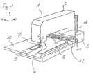
- a punching machine 1 for carrying out a method for discharging sheet metal parts is shown.
- An essential part of the punching machine 1 is a C-frame 2.
- the C-frame 2 consists of a torsion-resistant welded steel construction.
- a hydraulic unit 3 is provided, with which a plunger 6 is hydraulically driven.
- the drive of the plunger may also be provided by other drive means, e.g. an electric drive, done.
- a lower tool holder 4 On the lower inside of the C-frame 2, a lower tool holder 4 is provided for receiving tool lower parts 5 of later-described punching tools.
- the lower tool part 5 is rotatable about a first, not shown rotary drive in the X-Y plane through 360 ° and lockable in any angular position.
- the plunger 6 On the upper inside of the C-frame 2, the plunger 6 is provided.
- the plunger 6 receives a tool upper part 7 of the punching tool.
- the plunger 6 is also rotatable by 360 ° and can also be found in any angular position. For a second, not shown rotary drive is available.
- the rotary actuators are controlled by a machine control device, not shown, which is provided in a separate cabinet. Furthermore, a plunger control, as well as all linear drives for moving a sheet 8 and actuators for special functions, such as the folding and folding up a partial flap 9, controlled by the machine control device.
- the control device has as input and output means a keyboard and a monitor. The control functions are performed by microcontrollers. Processing programs and operating parameters are stored in a memory area of the control device.
- the control device controls the plunger 6 so that a predefined stroke is moved, and the position can be maintained, so that a defined distance between the upper tool part 7 and the lower tool part 5 is adjustable. Thus, a defined progress of a separation process of the sheet 9 can be adjusted.
- a machine table 10 On the lower inside of the C-frame 2 is a machine table 10, which has, centrally between its front end and the lower tool holder 4, the partial flap 9, and, arranged rear, a cross rail 11 with a linear magazine 12.
- clamping claws 13 are arranged for holding the sheet 8.
- the clamping claws 13 can be attached to the cross rail 11 at suitable locations.
- the clamping claws can be offset so that the sheet 8 is held securely, but the sheet 8 is not gripped on a surface to be machined.
- recordings for several punching tools 14 are available.
- the machine table 10 moves in a Y-direction together with the cross rail 11 to which the clamps 13 are fixed, with which the sheet 8 is held in a defined position, and the cross rail 11 moves in the X direction in the defined Position, with the sheet 8 over the machine table 10 slides. Then, a punching stroke is performed by the plunger 6. Following this, the next punching position is approached according to the same principle.
- the punching tools 14 are automatically changed, controlled by the machine control device, changed.
- the cross rail 11, driven by a linear drive, not shown, moves into a position in an X direction, so that the X position of the tool to be loaded corresponds to the X position of the lower tool holder 4.
- the cross rail 11 then moves together with the machine table 10, driven by a further linear drive, in a position in the Y direction in which a center axis of the lower tool part 5 and the upper part 7 with a central axis of the lower tool holder 4 and the plunger 6 match so that the lower tool part 5 can be received in the lower tool holder 4, and the upper tool part 7 can be accommodated in the plunger 6. If a tool is present in the plunger 6 and the lower tool holder 4, this is previously given to a free space in the linear magazine.
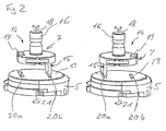
- the punching tool 14 is shown in an embodiment capable of punching at two different positions without moving the sheet 8, or changing the tool.
- the upper tool part 7 is received in a form-fitting and play-free manner in the plunger 6 via the stamp shank 16. With the aid of a sliding block 17, which is also in a positive, play-free engagement with the plunger 6, the upper tool part 7 can be positioned about an axis 18 in any orientation.
- a Stamp 15 provided at the bottom of the upper tool part 7 .
- the stamp has a rectangular contour with a defined width and thickness.
- the lower tool part 5 receives a die 19.
- two openings 20a, 20b are provided. These are symmetrical to an axis 21, about which the tool lower part 5 can be rotated, offset by 180 °.
- the contour of the openings 20a, 20b in the die 19 correspond to the contour of the punch 15, but are larger in size, depending on the sheet thickness to be processed, by a few tenths of a millimeter to produce a required cutting gap.
- the lower tool part 5 is received by its contour in the lower tool holder 4 positively and without play.
- the lower tool part 5 can be positioned rotated about an axis 21 in any orientation.
- the punching tool 14 is designed so that the punch 15 of the tool top part 7, as shown in the left-hand illustration, fits into the opening 20b of the die in one position, and after a rotation of 180 °, the punch 15 into the other opening 20a of FIG Die fits.
- a rectangular punched in the intermediate sheet 8 FIG. Fig. 1 ).
- the upper tool part not only one, but a plurality of stamp.
- the desired stamp is then activated for the machining process.
- the corresponding matrices are provided to the punches and the upper tool and the lower part of the tool are rotated according to the pitch angle.
- the contour of the punches and the dies can be executed except in a rectangular shape in one, in the context of the technical possibilities, any shape.
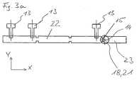
- Fig. 3a to 3d is a method for discharging a sheet metal part, explained here using the example of a residual strip of the sheet 8.
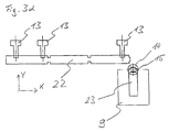
- a first punching operation, or a separation process in the discharge of a residual strip 22 is shown.
- the remaining strip 22 of the sheet 8 is held by a skeleton-free processing by at least two clamping claws 13.
- the remaining strip is positioned in a first method step so that the remaining strip comes to lie completely below the punch 15 of the punching tool with regard to its width (Y direction).
- the distance in the longitudinal direction (X-direction) to the nearest end is to be selected so that a section 23 is separated, which has a length up to the size of the partial flap.
- notches shown in the remaining strips are not mandatory.
- the residual strip 22, and thus the portion 23 to be separated and slipped off, are positioned in a region of the rotation axis 18, 21.
- the tool upper part 7 moves down, and by the punch 15 and the opening 20a in the die 19 is in a first working position from the remaining strip 22, a piece of sheet metal, a so-called stamped, punched out whose width (in the X direction) almost identical with the thickness (in the X direction) of the stamp is.
- the width (in the Y direction) of the punch 15 is greater than the width (in the Y direction) of the residual strip 22 at the location where the punching is performed.
- the section 23 is thereby separated from the residual strip 22.
- the stamping like other small punching waste, falls through an opening in the die down into a container.
- the upper tool part 7 then moves back to its upper position.
- the remnant strip 22 and the section 23 are moved in neither the X nor the Y direction.
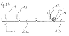
- Fig. 3b is the second punching and the ejection shown.
- the upper tool part 7 of the punching tool 14 is rotated by 180 ° about the axis 18 in a second working position, and the upper tool part 7 is moved down again.
- a second punch-out is produced by the punch by punching out a further punching tool.
- the width (in the Y direction) of the punch 15 is smaller than the width (in the Y direction) of the residual strip at the location where the punching is performed.
- the tool upper part 7 retains the lower position in a third method step, and the punch 15 remains in the opening 20b of the die 19, so that the punch 15 in the cut-out in the section 23 forms a positive connection between the punching tool 14 and generated in section 23.
- the movement of the tool upper part 7 can be controlled in an alternative 2nd method step so that the downward movement of the tool upper part is stopped when the punch 15 the section 23 touched and between the punch 15, the section 23 and the tool lower part 5 is a non-positive connection.
- This allows a damage-free surface, which is not a priority with residual strips 22, but allows for further use good parts a discharge without damage.
- the width of the punch 15 is less than the width of sheet metal part, here the remaining strip 22. In this case, the coincidence of the contour of the punch and the die is not required.
- the section 23 is only punched. This means that the movement of the upper tool part 7 is stopped when the underside of the punch 15 has penetrated approximately half the sheet thickness and only a portion of the sheet thickness has penetrated into the die 19. After the fourth method step described below, the stopped movement can then be continued up to the bottom dead center and thus a punching required for a component can be completed. For the section 23 of the residual strip 22 this has no relevance.
- the punch and the die with which the portion 23 is cut off have a shape and orientation such that, with respect to the axis 18, 21, the cutout on the side of the portion 23 results in a smaller opening than on the side of FIG ReststMails 22, the punch and the die can be arranged centrally to the axis 18, 21.
- the contour of the punch on the side of the portion 23 then outside the contour of the punch, so is greater than the punch, and therefore can clamp the portion 23 in the second process step.
- Fig. 3c It is shown how the remnant strip 22 is moved away from the section 23 held by the punching tool by means of the clamping claws 13 provided on the cross rail 11 and holding the residual strip 22 rearwardly in the Y direction. This retraction is required to prevent a collision between the residual strip 22 and the section 23 moved in the subsequently described method step 4. In other shaped punched out, in which no collision occurs in a 4th process step, the free driving is not required.
- Fig. 3d shows the tool 14 with the positive or non-positive connected to the punching tool 15 section 23 after step 4.
- the punch 14 is rotated by the lower tool holder 4 and the plunger 6 by 90 °. Due to the form or adhesion of the section 23 is also pivoted by 90 °. As a result, he assumes a position in which he is above the parts flap 9 of the punching machine 1 (see Fig. 1 ).
- the section 23 or the components are discharged via the flap folded down part 9. Below the parts flap 9, a corresponding receptacle is provided.
- the punching machine can also have a shaft.
- the components can also be removed by a removal system from the punching machine, wherein the components are brought in a suitable orientation by the pivoting movement.
- the tool upper part 7 is moved upward again.
- the positive or positive connection dissolves and the section 23 or a component to be ejected tilts, due to the position of its center of gravity, down to the parts flap 9, and slides along the parts flap 9 in the container.
- Metal sheets to be processed, from which further components are punched, are also positioned for the next processing operation.
- a sorting device is arranged below the parts flap, which, controlled by the machine control device, sorts the parts into the corresponding containers.
Abstract
Description
Die Erfindung betrifft ein Verfahren zum Ausschleusen von Blechteilen aus Stanzmaschinen.The invention relates to a method for discharging sheet metal parts from punching machines.
Blechteile mit Abmessungen in einem Bereich von ca. 5 cm bis 50 cm, die durch Stanzen in einer Stanzmaschine hergestellt werden, können nur schwer automatisiert aus der Stanzmaschine entnommen werden. Der Einsatz von Handlingsystemen mit Greifern wird zum Einen durch die verschiedenen Größen der Teile, und zum Anderen durch verschiedenen Orientierungen, selbst bei gleichen Teilen erschwert. Eine Möglichkeit, die Teile aus der Maschine zu entladen, ist der Einsatz von Handlingsystemen mit Sauggreifern. Der Einsatz dieser Greifer ist jedoch bei Blechteilen mit Ausstanzungen, insbesondere in diesem Bereich der Abmessungen, problematisch.Sheet metal parts with dimensions in a range of about 5 cm to 50 cm, which are produced by punching in a punching machine, are difficult to remove automatically from the punching machine. The use of handling systems with grippers is made difficult on the one hand by the different sizes of the parts, and on the other hand by different orientations, even with the same parts. One way to unload the parts from the machine is the use of handling systems with suction pads. However, the use of these grippers is problematic in sheet metal parts with punched, especially in this area of the dimensions.
Des Weiteren besteht das Problem, dass nach der Bearbeitung einer Blechtafel auf einer Stanzmaschine bei einer optimalen Materialausnutzung der Rest des in der Maschine verbleibenden Materials sehr klein ist. In günstigen Fällen bleibt durch eine solche restgitterfreie Bearbeitung nur noch ein Reststeifen, der durch die Spannpratzen festgehalten wird. Dieser Reststreifen ist automatisiert nur schwer prozesssicher zu entfernen, da er auf Grund seiner Länge nur schwer handhabbar ist. Bestehende Systeme haben sich nicht durchgesetzt, so dass die restgitterfreie Bearbeitung nicht unterstützt wird.Furthermore, there is the problem that after processing a metal sheet on a punching machine with an optimal material utilization, the rest of the remaining material in the machine material is very small. In favorable cases remains by such skeleton-free processing only a residual stiffness, which is held by the clamping claws. This residual strip is difficult to remove automatically with high process reliability, as it is difficult to handle due to its length. Existing systems have not prevailed, so that skeleton-free processing is not supported.
Daraus ergibt sich das Problem, dass der Reststreifen manuell entfernt werden muss, was eine vollautomatische Bearbeitung verhindert, und daher ein großes Kostenpotential darstellen kann.This results in the problem that the residual strip must be removed manually, which prevents fully automatic processing, and therefore can represent a large cost potential.
Es ist die Aufgabe der vorliegenden Erfindung, ein Verfahren zum automatisierten Ausschleusen von Blechteilen, und zum automatisierten Ausschleusen des Reststreifens, der nach einer restgitterfreien Bearbeitung in der Stanzmaschine verbleibt, zur Verfügung zu stellen.It is the object of the present invention to provide a method for the automated removal of sheet metal parts, and for the automated removal of the residual strip, which remains after a skeleton-free processing in the punching machine to provide.
Die Aufgabe wird durch das in Anspruch 1 beschriebene Verfahren gelöst. Weiterentwicklungen der Erfindung sind in den abhängigen Ansprüchen beschrieben.The object is achieved by the method described in
Das Verfahren bietet durch Freistanzen und Drehen der Blechteile die Möglichkeit, die Blechteile über die Teileklappe aus der Stanzmaschine zu entfernen.By free punching and turning of the sheet metal parts, the process offers the possibility of removing the sheet metal parts from the punching machine via the parts flap.
Die Erfindung wird unter Bezugnahme auf die beigefügten Zeichnungen erklärt.
- Fig. 1
- stellt eine Stanzmaschine in perspektivischer Ansicht dar;
- Fig. 2
- zeigt ein Stanzwerkzeug, das Stanzen in einer ersten und einer zweiten Position ermöglicht, ohne das zu stanzende Blech zu bewegen;
- Fig. 3a
- zeigt den ersten Stanzvorgang des Verfahrens, bzw. den Trennvorgang bei der Ausschleusung eines Reststrei- fens;
- Fig. 3b
- zeigt den zweiten Stanzvorgang;
- Fig. 3c
- zeigt das Freifahren des auszuschleusenden Blechteils;
- Fig. 3d
- zeigt das auszuschleusende Blechteil in der Position über der Teileklappe.
- Fig. 1
- shows a punching machine in perspective view;
- Fig. 2
- shows a punch that allows punching in a first and a second position without moving the sheet to be punched;
- Fig. 3a
- shows the first punching process of the process, or the separation process in the discharge of a residual strip;
- Fig. 3b
- shows the second punching operation;
- Fig. 3c
- shows the retraction of auszuschleusenden sheet metal part;
- Fig. 3d
- shows the auszuschleusende sheet metal part in the position above the parts flap.
In
Am hinteren Ende des C-Rahmens 2 ist ein Hydraulikaggregat 3 vorgesehen, mit dem ein Stößel 6 hydraulisch angetrieben wird.At the rear end of the C-frame 2, a
In alternativen Ausführungsformen kann der Antrieb des Stößels auch durch andere Antriebsmittel, z.B. einen elektrischen Antrieb, erfolgen.In alternative embodiments, the drive of the plunger may also be provided by other drive means, e.g. an electric drive, done.
Auf der unteren Innenseite des C-Rahmens 2 ist eine untere Werkzeugaufnahme 4 zum Aufnehmen von Werkzeugunterteilen 5 von später beschriebenen Stanzwerkzeugen vorgesehen. Das Werkzeugunterteil 5 ist über einen ersten nicht gezeigten Drehantrieb in der X-Y-Ebene um 360° drehbar und in jeder beliebigen Winkellage feststellbar.On the lower inside of the C-frame 2, a
Auf der oberen Innenseite des C-Rahmens 2 ist der Stößel 6 vorgesehen. Der Stößel 6 nimmt ein Werkzeugoberteil 7 des Stanzwerkzeugs auf. Der Stößel 6 ist ebenfalls um 360° drehbar und kann ebenfalls in jeder beliebigen Winkellage festgestellt werden. Dafür ist ein zweiter nicht gezeigter Drehantrieb vorhanden.On the upper inside of the C-frame 2, the plunger 6 is provided. The plunger 6 receives a tool
Die Drehantriebe werden von einer nicht gezeigten Maschinensteuerungsvorrichtung gesteuert, die in einem separaten Schaltschrank vorgesehen ist. Weiterhin wird auch eine Stößelsteuerung, sowie sämtliche Linearantriebe zur Bewegung eines Blechs 8 und Aktuatoren für Sonderfunktionen, beispielsweise das Ab- und Hochklappen einer Teileklappe 9, durch die Maschinensteuerungsvorrichtung gesteuert. Die Steuerungsvorrichtung weist als Ein- und Ausgabemittel eine Tastatur und einen Monitor auf. Die Steuerungsfunktionen werden von Mikrocontrollern ausgeführt. Bearbeitungsprogramme und Betriebsparameter sind in einem Speicherbereich der Steuerungsvorrichtung abgespeichert.The rotary actuators are controlled by a machine control device, not shown, which is provided in a separate cabinet. Furthermore, a plunger control, as well as all linear drives for moving a
Die Steuerungsvorrichtung steuert den Stößel 6 so, dass ein vordefinierter Hubweg verfahren wird, und die Position eingehalten werden kann, so dass ein definierter Abstand zwischen dem Werkzeugoberteil 7 und dem Werkzeugunterteil 5 einstellbar ist. Damit kann ein definierter Fortschritt eines Trennvorgangs des Blechs 9 eingestellt werden.The control device controls the plunger 6 so that a predefined stroke is moved, and the position can be maintained, so that a defined distance between the
Auf der unteren Innenseite des C-Rahmens 2 ist ein Maschinentisch 10, der zentral, zwischen seinem vorderen Ende und der unteren Werkzeugaufnahme 4, die Teileklappe 9 aufweist, und, hinten angeordnet, eine Querschiene 11 mit einem Linearmagazin 12 aufweist. An der Querschiene 11 sind Spannpratzen 13 zum Festhalten des Blechs 8 angeordnet. Die Spannpratzen 13 können an geeigneten Stellen an der Querschiene 11 befestigt werden. Die Spannpratzen können so versetzt werden, dass das Blech 8 sicher gehalten wird, aber das Blech 8 nicht an einer zu bearbeitenden Fläche gegriffen wird. In dem Linearmagazin 12 sind Aufnahmen für mehrere Stanzwerkzeuge 14 vorhanden.On the lower inside of the C-frame 2 is a machine table 10, which has, centrally between its front end and the
Zum Stanzen fährt der Maschinentisch 10 in einer Y-Richtung gemeinsam mit der Querschiene 11, an der die Spannpratzen 13 befestigt sind, mit denen das Blech 8 gehalten wird, in eine definierte Position, und die Querschiene 11 fährt in X-Richtung in die definierte Position, wobei das Blech 8 über den Maschinentisch 10 gleitet. Dann wird von dem Stößel 6 ein Stanzhub durchgeführt. Im Anschluss daran wird nach dem selben Prinzip die nächste Stanzposition angefahren.For punching the machine table 10 moves in a Y-direction together with the cross rail 11 to which the
Die Stanzwerkzeuge 14 werden automatisch, durch die Maschinensteuerungsvorrichtung angesteuert, gewechselt. Dazu fährt die Querschiene 11, angetrieben von einem nicht gezeigten Linearantrieb, in eine Position in einer X-Richtung, so dass die X-Position des einzuwechselnden Werkzeugs der X-Position der unteren Werkzeugaufnahme 4 entspricht. Die Querschiene 11 fährt dann gemeinsam mit dem Maschinentisch 10, von einem weiteren Linearantrieb angetrieben, in eine Position in der Y-Richtung, in der eine Mittelachse des Werkzeugunterteils 5 und des Werkzeugoberteil 7 mit einer Mittelachse der unteren Werkzeugaufnahme 4 und dem Stößel 6 übereinstimmen, so dass das Werkzeugunterteil 5 in die untere Werkzeugaufnahme 4 aufgenommen werden kann, und das Werkzeugoberteil 7 in den Stößel 6 aufgenommen werden kann. Sofern in dem Stößel 6 und der unteren Werkzeugaufnahme 4 ein Werkzeug vorhanden ist, wird dieses vorher an einen freien Platz im Linearmagazin abgegeben.The
In
Das Werkzeugoberteil 7 wird über den Stempelschaft 16 formschlüssig und spielfrei in dem Stößel 6 aufgenommen. Mit Hilfe eines Nutensteins 17, der mit dem Stößel 6 ebenfalls in einem formschlüssigen, spielfreien Eingriff ist, ist das Werkzeugoberteil 7 in einer beliebigen Orientierung um eine Achse 18 positionierbar. An der Unterseite des Werkzeugoberteils 7 ist ein Stempel 15 vorgesehen. Der Stempel besitzt eine rechteckige Kontur mit einer definierten Breite und Dicke.The
Das Werkzeugunterteil 5 nimmt eine Matrize 19 auf. In der Matrize sind zwei Öffnungen 20a, 20b vorgesehen. Diese sind symmetrisch zu einer Achse 21, um die das Werkzeugunterteil 5 gedreht werden kann, um 180° versetzt. Die Kontur der Öffnungen 20a, 20b in der Matrize 19 entsprechen der Kontur des Stempels 15, sind aber in ihren Abmessungen, abhängig von der zu bearbeitenden Blechstärke, um wenige Zehntelmillimeter größer, um einen erforderlichen Schneidspalt zu erzeugen.The
Das Werkzeugunterteil 5 ist durch seine Kontur in der unteren Werkzeugaufnahme 4 formschlüssig und spielfrei aufgenommen. Damit kann das Werkzeugunterteil 5 um eine Achse 21 gedreht in einer beliebigen Orientierung positioniert werden.The
Das Stanzwerkzeug 14 ist so ausgeführt, dass der Stempel 15 des Werkzeugoberteils 7, wie in der linken Darstellung gezeigt, in einer Stellung in die Öffnung 20b der Matrize passt, und nach einer Drehung von 180°, der Stempel 15 in die andere Öffnung 20a der Matrize passt. Beim Ineinander fahren der beiden Werkzeugteile 5, 7 entsteht eine rechteckige Ausstanzung in dem dazwischen liegenden Blech 8 (
In weiteren Ausführungsformen weist das Werkzeugoberteil nicht nur einen, sondern mehrere Stempel auf. Für den Bearbeitungsvorgang wird dann jeweils der gewünschte Stempel aktiviert. Im Werkzeugunterteil sind dann die entsprechenden Matrizen zu den Stempeln vorgesehen und das Werkzeugoberteil und das Werkzeugunterteil werden entsprechend der Teilungswinkel verdreht.In further embodiments, the upper tool part not only one, but a plurality of stamp. The desired stamp is then activated for the machining process. In the lower part of the tool then the corresponding matrices are provided to the punches and the upper tool and the lower part of the tool are rotated according to the pitch angle.
Die Kontur der Stempel und der Matrizen kann außer in einer rechteckigen Form auch in einer, im Rahmen der technischen Möglichkeiten, beliebigen Form ausgeführt sein.The contour of the punches and the dies can be executed except in a rectangular shape in one, in the context of the technical possibilities, any shape.
In den
In
Wie vorstehend ausgeführt, werden der Reststreifen 22 und damit der abzutrennende und zu auszuschleusende Abschnitt 23 in einem Bereich der Drehachse 18, 21 positioniert. Dies bedeutet, dass sich die Position des Stempels 15 vor dem später beschriebenen 2. Verfahrensschritt bezüglich der Achse 18, 21 auf der Seite des Reststreifens 22 des auszuschleusenden Teils befindet. Danach fährt das Werkzeugoberteil 7 nach unten, und durch den Stempel 15 und die Öffnung 20a in der Matrize 19 wird in einer ersten Arbeitsposition aus dem Reststreifen 22 ein Blechstück, ein so genannter Stanzbutzen, ausgestanzt, dessen Breite (in X-Richtung) fast identisch mit der Dicke (in X-Richtung) des Stempels ist. Die Breite (in Y-Richtung) des Stempels 15 ist größer als die Breite (in Y-Richtung) des Reststreifens 22 an der Stelle, an der die Stanzung durchgeführt wird. Der Abschnitt 23 wird dadurch vom Reststreifen 22 abgetrennt. Der Stanzbutzen fällt, wie auch andere kleine Stanzabfälle, durch eine Öffnung in der Matrize nach unten in einen Behälter. Das Werkzeugoberteil 7 fährt dann wieder in seine obere Position. Der Reststreifen 22 und der Abschnitt 23 werden weder in der X- noch in der Y-Richtung bewegt.As stated above, the
In
Nach der Stanzbewegung behält das Werkzeugoberteil 7 in einem 3. Verfahrenschritt die untere Stellung bei, und der Stempel 15 verbleibt in der Öffnung 20b der Matrize 19, so dass der Stempel 15 in der Ausstanzung in dem Abschnitt 23 eine formschlüssige Verbindung zwischen dem Stanzwerkzeug 14 und dem Abschnitt 23 erzeugt.After the punching movement, the tool
Alternativ zu dem Stanzvorgang des 2. Verfahrenschritts, bei dem ein Stanzbutzen aus dem Reststreifen 22 herausgestanzt wird, kann die Bewegung des Werkzeugoberteils 7 in einem alternativen 2. Verfahrensschritt so gesteuert sein, dass die Abwärtsbewegung des Werkzeugoberteils gestoppt wird, wenn der Stempel 15 den Abschnitt 23 berührt und zwischen dem Stempel 15, dem Abschnitt 23 und dem Werkzeugunterteil 5 eine kraftschlüssige Verbindung besteht. Dies ermöglicht eine beschädigungsfreie Oberfläche, was zwar bei Reststreifen 22 nicht von Priorität ist, aber bei weiterzuverwendenden Gutteilen ein Ausschleusen ohne Beschädigungen ermöglicht. Außerdem ist es hierbei nicht erforderlich, dass die Breite des Stempels 15 geringer ist als die Breite es Blechteils, hier des Reststreifens 22. In diesem Fall ist die Übereinstimmung der Kontur des Stempels und der Matrize nicht erforderlich.As an alternative to the punching operation of the second method step, in which a punched slug is punched out of the
In einer weiteren Alternative des 2. Verfahrensschritts wird der Abschnitt 23 nur angestanzt. Das heißt, dass die Bewegung des Werkzeugoberteils 7 gestoppt wird, wenn die Unterseite des Stempels 15 ca. die halbe Blechstärke durchdrungen hat und nur ein Teil der Blechstärke in die Matrize 19 eingedrungen ist. Nach dem nachfolgend beschriebenen 4. Verfahrensschritt kann dann die angehaltene Bewegung bis zu dem unteren Totpunkt fortgesetzt werden und so eine für ein Bauteil benötigte Ausstanzung vervollständigt werden. Für den Abschnitt 23 des Reststreifens 22 hat dies keine Relevanz.In a further alternative of the second method step, the
In dem Fall, in dem der Stempel und die Matrize mit denen der Abschnitt 23 abgetrennt wird, eine Form und Orientierung aufweisen, so dass bezüglich der Achse 18, 21 die Ausstanzung auf der Seite des Abschnitts 23 eine kleinere Öffnung ergibt als auf der Seite des Reststreifens 22, können der Stempel und die Matrize zentrisch zu der Achse 18, 21 angeordnet sein. Bei einer Drehung um 180°, oder einen anderen geeigneten Drehwinkel, liegt die Kontur des Stempels auf der Seite des Abschnitts 23 dann außerhalb der Kontur der Ausstanzung, ist also größer als die Ausstanzung, und kann daher den Abschnitt 23 im zweiten Verfahrensschritt klemmen.In the case where the punch and the die with which the
Weiterhin kann bei der Verwendung eines Werkzeugoberteils 7 mit mehreren Stempeln 15, zum Abtrennen des Abschnitts 23 ein anderer Stempel, als im zweiten Verfahrensschritt verwendet werden.Furthermore, when using a tool
In
Beim Ausschleusen von Bauteilen über die Teileklappe 9 ist, falls diese Situation nicht bereits vorliegt, eine Schwenkbewegung durchzuführen, so dass sich die Bauteile nach der Schwenkbewegung im Wesentlichen über der Teileklappe 9 befinden.When removing components via the
Der Abschnitt 23 wird oder die Bauteile werden über die nach unten geklappte Teileklappe 9 ausgeschleust. Unterhalb der Teileklappe 9 ist ein entsprechender Auffangbehälter vorgesehen. Alternativ zu dem Ausschleusen über die Teileklappe 9 kann die Stanzmaschine auch einen Schacht aufweisen. Weiterhin können die Bauteile auch durch ein Entnahmesystem aus der Stanzmaschine entnommen werden, wobei durch die Schwenkbewegung die Bauteile in eine geeignete Orientierung gebracht werden.The
Im Verfahrensschritt 5 wird das Werkzeugoberteil 7 wieder nach oben bewegt. Dabei löst sich die kraft- oder formschlüssige Verbindung und der Abschnitt 23 oder ein auszuschleusendes Bauteil kippt, bedingt durch die Lage seines Schwerpunkts, nach unten auf die Teileklappe 9, und gleitet entlang der Teileklappe 9 in den Behälter.In
Anschließend wird im Falle des Ausschleusens des Reststreifens 22 dieser für den nächsten Abtrenn- und Ausschleusvorgang positioniert, und der Vorgang wiederholt, bis der Reststreifen vollständig ausgeschleust ist.Subsequently, in the case of discharging the
Zu bearbeitende Blechtafeln, aus denen weitere Bauteile ausgestanzt werden, werden ebenfalls für den nächsten Bearbeitungsvorgang positioniert.Metal sheets to be processed, from which further components are punched, are also positioned for the next processing operation.
Optional ist bei einem Ausschleusen von Blech-Bauteilen eine Sortiervorrichtung unterhalb der Teileklappe angeordnet, die, von der Maschinensteuerungsvorrichtung angesteuert, die Teile in die entsprechenden Behälter sortiert.Optionally, when sorting sheet metal components, a sorting device is arranged below the parts flap, which, controlled by the machine control device, sorts the parts into the corresponding containers.
Claims (12)
Priority Applications (3)
| Application Number | Priority Date | Filing Date | Title |
|---|---|---|---|
| PL08019520T PL2184116T3 (en) | 2008-11-07 | 2008-11-07 | Method for discharging sheet metal from stamping machines |
| EP08019520A EP2184116B1 (en) | 2008-11-07 | 2008-11-07 | Method for discharging sheet metal from stamping machines |
| AT08019520T ATE515335T1 (en) | 2008-11-07 | 2008-11-07 | METHOD FOR EXHAUSTING SHEET METAL PARTS FROM PUNCHING MACHINES |
Applications Claiming Priority (1)
| Application Number | Priority Date | Filing Date | Title |
|---|---|---|---|
| EP08019520A EP2184116B1 (en) | 2008-11-07 | 2008-11-07 | Method for discharging sheet metal from stamping machines |
Publications (2)
| Publication Number | Publication Date |
|---|---|
| EP2184116A1 true EP2184116A1 (en) | 2010-05-12 |
| EP2184116B1 EP2184116B1 (en) | 2011-07-06 |
Family
ID=40374222
Family Applications (1)
| Application Number | Title | Priority Date | Filing Date |
|---|---|---|---|
| EP08019520A Active EP2184116B1 (en) | 2008-11-07 | 2008-11-07 | Method for discharging sheet metal from stamping machines |
Country Status (3)
| Country | Link |
|---|---|
| EP (1) | EP2184116B1 (en) |
| AT (1) | ATE515335T1 (en) |
| PL (1) | PL2184116T3 (en) |
Cited By (7)
| Publication number | Priority date | Publication date | Assignee | Title |
|---|---|---|---|---|
| WO2012028549A1 (en) * | 2010-08-31 | 2012-03-08 | Trumpf Werkzeugmaschinen Gmbh + Co. Kg | Method for machining a workpiece on a machine tool |
| CN107876623A (en) * | 2017-11-28 | 2018-04-06 | 安徽机电职业技术学院 | A kind of single hole punched device of thin discs |
| CN107983822A (en) * | 2018-01-07 | 2018-05-04 | 安徽合力股份有限公司 | A kind of trimming blanking apparatus of forklift truck water tank cover plate |
| CN113649491A (en) * | 2021-08-10 | 2021-11-16 | 鄂尔多斯市冠盛汽车部件有限公司 | Continuous stamping equipment for automobile body inner plates |
| CN113878027A (en) * | 2021-09-23 | 2022-01-04 | 江西乔源科技有限公司 | Panel punching device for computer case |
| FR3121622A1 (en) * | 2021-04-12 | 2022-10-14 | Siif | HEAD FOR GRIPPING AND PUNCHING A PART ALLOWING ITS DRIVE IN ROTATION FOR ITS MACHINING |
| CN116967354A (en) * | 2023-09-22 | 2023-10-31 | 新乡天丰机械制造有限公司 | Online flaring machine for plate processing |
Citations (5)
| Publication number | Priority date | Publication date | Assignee | Title |
|---|---|---|---|---|
| US3979985A (en) | 1973-08-06 | 1976-09-14 | U.S. Amada, Ltd. | Sheet transfer between a turret punch press and an adjacent apparatus |
| US4602541A (en) * | 1984-12-06 | 1986-07-29 | Trumpf Gmbh & Co. | Punch press with means for rotating the workpiece and method of using same and tooling therefor |
| US4690021A (en) * | 1977-07-15 | 1987-09-01 | Strippit/Di-Acro-Houdaille, Inc. | Automatic load unload turret punch |
| JPH0452036A (en) * | 1990-06-15 | 1992-02-20 | Oki Electric Ind Co Ltd | Sorting device into product and waste in working machine |
| EP0845314A1 (en) * | 1996-11-29 | 1998-06-03 | Murata Kikai Kabushiki Kaisha | Punch press machine and method of repositioning the workpiece on the table of such machine |
-
2008
- 2008-11-07 PL PL08019520T patent/PL2184116T3/en unknown
- 2008-11-07 AT AT08019520T patent/ATE515335T1/en active
- 2008-11-07 EP EP08019520A patent/EP2184116B1/en active Active
Patent Citations (5)
| Publication number | Priority date | Publication date | Assignee | Title |
|---|---|---|---|---|
| US3979985A (en) | 1973-08-06 | 1976-09-14 | U.S. Amada, Ltd. | Sheet transfer between a turret punch press and an adjacent apparatus |
| US4690021A (en) * | 1977-07-15 | 1987-09-01 | Strippit/Di-Acro-Houdaille, Inc. | Automatic load unload turret punch |
| US4602541A (en) * | 1984-12-06 | 1986-07-29 | Trumpf Gmbh & Co. | Punch press with means for rotating the workpiece and method of using same and tooling therefor |
| JPH0452036A (en) * | 1990-06-15 | 1992-02-20 | Oki Electric Ind Co Ltd | Sorting device into product and waste in working machine |
| EP0845314A1 (en) * | 1996-11-29 | 1998-06-03 | Murata Kikai Kabushiki Kaisha | Punch press machine and method of repositioning the workpiece on the table of such machine |
Cited By (11)
| Publication number | Priority date | Publication date | Assignee | Title |
|---|---|---|---|---|
| WO2012028549A1 (en) * | 2010-08-31 | 2012-03-08 | Trumpf Werkzeugmaschinen Gmbh + Co. Kg | Method for machining a workpiece on a machine tool |
| CN103237612A (en) * | 2010-08-31 | 2013-08-07 | 通快机床两合公司 | Method for machining a workpiece on a machine tool |
| US8887366B2 (en) | 2010-08-31 | 2014-11-18 | Trumpf Werkzeugmaschinen Gmbh + Co. Kg | Processing workpieces on machine tools |
| CN103237612B (en) * | 2010-08-31 | 2015-03-18 | 通快机床两合公司 | Method for machining a workpiece on a machine tool |
| CN107876623A (en) * | 2017-11-28 | 2018-04-06 | 安徽机电职业技术学院 | A kind of single hole punched device of thin discs |
| CN107876623B (en) * | 2017-11-28 | 2019-09-24 | 绍兴市米莉农业科技有限公司 | A kind of single hole punched device of thin discs |
| CN107983822A (en) * | 2018-01-07 | 2018-05-04 | 安徽合力股份有限公司 | A kind of trimming blanking apparatus of forklift truck water tank cover plate |
| FR3121622A1 (en) * | 2021-04-12 | 2022-10-14 | Siif | HEAD FOR GRIPPING AND PUNCHING A PART ALLOWING ITS DRIVE IN ROTATION FOR ITS MACHINING |
| CN113649491A (en) * | 2021-08-10 | 2021-11-16 | 鄂尔多斯市冠盛汽车部件有限公司 | Continuous stamping equipment for automobile body inner plates |
| CN113878027A (en) * | 2021-09-23 | 2022-01-04 | 江西乔源科技有限公司 | Panel punching device for computer case |
| CN116967354A (en) * | 2023-09-22 | 2023-10-31 | 新乡天丰机械制造有限公司 | Online flaring machine for plate processing |
Also Published As
| Publication number | Publication date |
|---|---|
| EP2184116B1 (en) | 2011-07-06 |
| PL2184116T3 (en) | 2011-12-30 |
| ATE515335T1 (en) | 2011-07-15 |
Similar Documents
| Publication | Publication Date | Title |
|---|---|---|
| EP2184116B1 (en) | Method for discharging sheet metal from stamping machines | |
| EP2340147B1 (en) | Processing machine for six-sided processing | |
| EP1964653A1 (en) | Plate partitioning facility for partitioning plate-shaped workpieces and method for its operation | |
| EP0906161B1 (en) | Shaping machine for sheet-like workpieces, especially for bending the edges of sheet-steel components | |
| DE102009013437A1 (en) | Eject tool for machining workpieces | |
| EP2656937B1 (en) | Method for introducing a deformation in a plate-like workpiece | |
| EP1683601B1 (en) | Process for laser cutting of sheets and laser cutting device for carrying out the process | |
| EP2452790A1 (en) | Processing station for a stamping machine and method for removing a test blank | |
| EP2198991B1 (en) | Sheet metal loading and unloading unit with a tool holder for sheet metal processing machines | |
| CH662295A5 (en) | METHOD FOR CUTTING OUT OR SEPARATING PARTS FROM A WORKPIECE PANEL ON A CUTTING PRESS, AND CUTTING PRESS FOR CARRYING OUT THE PROCESS. | |
| EP3078432B1 (en) | Tool for a processing machine | |
| DE10019368B4 (en) | Method and device for producing sheet metal | |
| EP2184118B1 (en) | Stepped holding down clamp and method of removing sheet metal parts from punching machines | |
| EP3790681B1 (en) | Device and method for the removal of a workpiece | |
| DE3730446C2 (en) | Tool changing device for a machine tool, in particular a punch press | |
| DE3312233C1 (en) | Punching machine and notching machine | |
| EP3362201B1 (en) | Method for operating a bending press and such a bending press | |
| EP2532452A1 (en) | Method and tool for punching and straightening sheet metal | |
| EP0276634A1 (en) | Method and installation for manufacturing work pieces | |
| WO2018210722A1 (en) | Feeding device and feeding method | |
| EP0585576B1 (en) | Punching machine | |
| DE2152784A1 (en) | Apparatus and method for inserting self-clinching nuts into a workpiece | |
| DE10009974B4 (en) | Device and method for separating individual circuit boards from multiple panels | |
| DE10340794B4 (en) | Follower tool for producing a complex shaped and provided with openings in different planes component | |
| DE102008051804B4 (en) | Method and device for shearing through pins |
Legal Events
| Date | Code | Title | Description |
|---|---|---|---|
| PUAI | Public reference made under article 153(3) epc to a published international application that has entered the european phase |
Free format text: ORIGINAL CODE: 0009012 |
|
| AK | Designated contracting states |
Kind code of ref document: A1 Designated state(s): AT BE BG CH CY CZ DE DK EE ES FI FR GB GR HR HU IE IS IT LI LT LU LV MC MT NL NO PL PT RO SE SI SK TR |
|
| AX | Request for extension of the european patent |
Extension state: AL BA MK RS |
|
| 17P | Request for examination filed |
Effective date: 20100712 |
|
| 17Q | First examination report despatched |
Effective date: 20100816 |
|
| AKX | Designation fees paid |
Designated state(s): AT BE BG CH CY CZ DE DK EE ES FI FR GB GR HR HU IE IS IT LI LT LU LV MC MT NL NO PL PT RO SE SI SK TR |
|
| GRAP | Despatch of communication of intention to grant a patent |
Free format text: ORIGINAL CODE: EPIDOSNIGR1 |
|
| GRAS | Grant fee paid |
Free format text: ORIGINAL CODE: EPIDOSNIGR3 |
|
| GRAA | (expected) grant |
Free format text: ORIGINAL CODE: 0009210 |
|
| AK | Designated contracting states |
Kind code of ref document: B1 Designated state(s): AT BE BG CH CY CZ DE DK EE ES FI FR GB GR HR HU IE IS IT LI LT LU LV MC MT NL NO PL PT RO SE SI SK TR |
|
| REG | Reference to a national code |
Ref country code: GB Ref legal event code: FG4D Free format text: NOT ENGLISH |
|
| REG | Reference to a national code |
Ref country code: CH Ref legal event code: EP |
|
| REG | Reference to a national code |
Ref country code: CH Ref legal event code: NV Representative=s name: NOVAGRAAF INTERNATIONAL SA |
|
| REG | Reference to a national code |
Ref country code: IE Ref legal event code: FG4D Free format text: LANGUAGE OF EP DOCUMENT: GERMAN |
|
| REG | Reference to a national code |
Ref country code: DE Ref legal event code: R096 Ref document number: 502008004094 Country of ref document: DE Effective date: 20110825 |
|
| REG | Reference to a national code |
Ref country code: NL Ref legal event code: VDEP Effective date: 20110706 |
|
| PG25 | Lapsed in a contracting state [announced via postgrant information from national office to epo] |
Ref country code: SI Free format text: LAPSE BECAUSE OF FAILURE TO SUBMIT A TRANSLATION OF THE DESCRIPTION OR TO PAY THE FEE WITHIN THE PRESCRIBED TIME-LIMIT Effective date: 20110706 |
|
| REG | Reference to a national code |
Ref country code: PL Ref legal event code: T3 |
|
| PG25 | Lapsed in a contracting state [announced via postgrant information from national office to epo] |
Ref country code: IS Free format text: LAPSE BECAUSE OF FAILURE TO SUBMIT A TRANSLATION OF THE DESCRIPTION OR TO PAY THE FEE WITHIN THE PRESCRIBED TIME-LIMIT Effective date: 20111106 Ref country code: SE Free format text: LAPSE BECAUSE OF FAILURE TO SUBMIT A TRANSLATION OF THE DESCRIPTION OR TO PAY THE FEE WITHIN THE PRESCRIBED TIME-LIMIT Effective date: 20110706 Ref country code: NO Free format text: LAPSE BECAUSE OF FAILURE TO SUBMIT A TRANSLATION OF THE DESCRIPTION OR TO PAY THE FEE WITHIN THE PRESCRIBED TIME-LIMIT Effective date: 20111006 Ref country code: NL Free format text: LAPSE BECAUSE OF FAILURE TO SUBMIT A TRANSLATION OF THE DESCRIPTION OR TO PAY THE FEE WITHIN THE PRESCRIBED TIME-LIMIT Effective date: 20110706 Ref country code: HR Free format text: LAPSE BECAUSE OF FAILURE TO SUBMIT A TRANSLATION OF THE DESCRIPTION OR TO PAY THE FEE WITHIN THE PRESCRIBED TIME-LIMIT Effective date: 20110706 Ref country code: PT Free format text: LAPSE BECAUSE OF FAILURE TO SUBMIT A TRANSLATION OF THE DESCRIPTION OR TO PAY THE FEE WITHIN THE PRESCRIBED TIME-LIMIT Effective date: 20111107 Ref country code: FI Free format text: LAPSE BECAUSE OF FAILURE TO SUBMIT A TRANSLATION OF THE DESCRIPTION OR TO PAY THE FEE WITHIN THE PRESCRIBED TIME-LIMIT Effective date: 20110706 Ref country code: LT Free format text: LAPSE BECAUSE OF FAILURE TO SUBMIT A TRANSLATION OF THE DESCRIPTION OR TO PAY THE FEE WITHIN THE PRESCRIBED TIME-LIMIT Effective date: 20110706 |
|
| REG | Reference to a national code |
Ref country code: IE Ref legal event code: FD4D |
|
| PG25 | Lapsed in a contracting state [announced via postgrant information from national office to epo] |
Ref country code: GR Free format text: LAPSE BECAUSE OF FAILURE TO SUBMIT A TRANSLATION OF THE DESCRIPTION OR TO PAY THE FEE WITHIN THE PRESCRIBED TIME-LIMIT Effective date: 20111007 Ref country code: LV Free format text: LAPSE BECAUSE OF FAILURE TO SUBMIT A TRANSLATION OF THE DESCRIPTION OR TO PAY THE FEE WITHIN THE PRESCRIBED TIME-LIMIT Effective date: 20110706 Ref country code: CY Free format text: LAPSE BECAUSE OF FAILURE TO SUBMIT A TRANSLATION OF THE DESCRIPTION OR TO PAY THE FEE WITHIN THE PRESCRIBED TIME-LIMIT Effective date: 20110706 |
|
| PG25 | Lapsed in a contracting state [announced via postgrant information from national office to epo] |
Ref country code: SK Free format text: LAPSE BECAUSE OF FAILURE TO SUBMIT A TRANSLATION OF THE DESCRIPTION OR TO PAY THE FEE WITHIN THE PRESCRIBED TIME-LIMIT Effective date: 20110706 Ref country code: IE Free format text: LAPSE BECAUSE OF FAILURE TO SUBMIT A TRANSLATION OF THE DESCRIPTION OR TO PAY THE FEE WITHIN THE PRESCRIBED TIME-LIMIT Effective date: 20110706 |
|
| PLBE | No opposition filed within time limit |
Free format text: ORIGINAL CODE: 0009261 |
|
| STAA | Information on the status of an ep patent application or granted ep patent |
Free format text: STATUS: NO OPPOSITION FILED WITHIN TIME LIMIT |
|
| BERE | Be: lapsed |
Owner name: TRUMPF WERKZEUGMASCHINEN G.M.B.H. + CO. KG Effective date: 20111130 |
|
| PG25 | Lapsed in a contracting state [announced via postgrant information from national office to epo] |
Ref country code: RO Free format text: LAPSE BECAUSE OF FAILURE TO SUBMIT A TRANSLATION OF THE DESCRIPTION OR TO PAY THE FEE WITHIN THE PRESCRIBED TIME-LIMIT Effective date: 20110706 Ref country code: EE Free format text: LAPSE BECAUSE OF FAILURE TO SUBMIT A TRANSLATION OF THE DESCRIPTION OR TO PAY THE FEE WITHIN THE PRESCRIBED TIME-LIMIT Effective date: 20110706 |
|
| 26N | No opposition filed |
Effective date: 20120411 |
|
| PG25 | Lapsed in a contracting state [announced via postgrant information from national office to epo] |
Ref country code: MC Free format text: LAPSE BECAUSE OF NON-PAYMENT OF DUE FEES Effective date: 20111130 Ref country code: DK Free format text: LAPSE BECAUSE OF FAILURE TO SUBMIT A TRANSLATION OF THE DESCRIPTION OR TO PAY THE FEE WITHIN THE PRESCRIBED TIME-LIMIT Effective date: 20110706 |
|
| REG | Reference to a national code |
Ref country code: DE Ref legal event code: R097 Ref document number: 502008004094 Country of ref document: DE Effective date: 20120411 |
|
| PG25 | Lapsed in a contracting state [announced via postgrant information from national office to epo] |
Ref country code: BE Free format text: LAPSE BECAUSE OF NON-PAYMENT OF DUE FEES Effective date: 20111130 |
|
| PG25 | Lapsed in a contracting state [announced via postgrant information from national office to epo] |
Ref country code: MT Free format text: LAPSE BECAUSE OF FAILURE TO SUBMIT A TRANSLATION OF THE DESCRIPTION OR TO PAY THE FEE WITHIN THE PRESCRIBED TIME-LIMIT Effective date: 20110706 |
|
| PG25 | Lapsed in a contracting state [announced via postgrant information from national office to epo] |
Ref country code: ES Free format text: LAPSE BECAUSE OF FAILURE TO SUBMIT A TRANSLATION OF THE DESCRIPTION OR TO PAY THE FEE WITHIN THE PRESCRIBED TIME-LIMIT Effective date: 20111017 |
|
| PG25 | Lapsed in a contracting state [announced via postgrant information from national office to epo] |
Ref country code: LU Free format text: LAPSE BECAUSE OF NON-PAYMENT OF DUE FEES Effective date: 20111107 |
|
| PG25 | Lapsed in a contracting state [announced via postgrant information from national office to epo] |
Ref country code: BG Free format text: LAPSE BECAUSE OF FAILURE TO SUBMIT A TRANSLATION OF THE DESCRIPTION OR TO PAY THE FEE WITHIN THE PRESCRIBED TIME-LIMIT Effective date: 20111006 |
|
| PG25 | Lapsed in a contracting state [announced via postgrant information from national office to epo] |
Ref country code: TR Free format text: LAPSE BECAUSE OF FAILURE TO SUBMIT A TRANSLATION OF THE DESCRIPTION OR TO PAY THE FEE WITHIN THE PRESCRIBED TIME-LIMIT Effective date: 20110706 |
|
| PG25 | Lapsed in a contracting state [announced via postgrant information from national office to epo] |
Ref country code: HU Free format text: LAPSE BECAUSE OF FAILURE TO SUBMIT A TRANSLATION OF THE DESCRIPTION OR TO PAY THE FEE WITHIN THE PRESCRIBED TIME-LIMIT Effective date: 20110706 |
|
| REG | Reference to a national code |
Ref country code: FR Ref legal event code: PLFP Year of fee payment: 8 |
|
| REG | Reference to a national code |
Ref country code: FR Ref legal event code: PLFP Year of fee payment: 9 |
|
| REG | Reference to a national code |
Ref country code: FR Ref legal event code: PLFP Year of fee payment: 10 |
|
| PGFP | Annual fee paid to national office [announced via postgrant information from national office to epo] |
Ref country code: AT Payment date: 20211119 Year of fee payment: 14 Ref country code: DE Payment date: 20211118 Year of fee payment: 14 Ref country code: CZ Payment date: 20211108 Year of fee payment: 14 Ref country code: FR Payment date: 20211122 Year of fee payment: 14 Ref country code: GB Payment date: 20211118 Year of fee payment: 14 |
|
| PGFP | Annual fee paid to national office [announced via postgrant information from national office to epo] |
Ref country code: IT Payment date: 20211119 Year of fee payment: 14 Ref country code: CH Payment date: 20211119 Year of fee payment: 14 |
|
| PGFP | Annual fee paid to national office [announced via postgrant information from national office to epo] |
Ref country code: PL Payment date: 20211020 Year of fee payment: 14 |
|
| REG | Reference to a national code |
Ref country code: DE Ref legal event code: R119 Ref document number: 502008004094 Country of ref document: DE |
|
| REG | Reference to a national code |
Ref country code: CH Ref legal event code: PL |
|
| REG | Reference to a national code |
Ref country code: AT Ref legal event code: MM01 Ref document number: 515335 Country of ref document: AT Kind code of ref document: T Effective date: 20221107 |
|
| GBPC | Gb: european patent ceased through non-payment of renewal fee |
Effective date: 20221107 |
|
| PG25 | Lapsed in a contracting state [announced via postgrant information from national office to epo] |
Ref country code: LI Free format text: LAPSE BECAUSE OF NON-PAYMENT OF DUE FEES Effective date: 20221130 Ref country code: CZ Free format text: LAPSE BECAUSE OF NON-PAYMENT OF DUE FEES Effective date: 20221107 Ref country code: CH Free format text: LAPSE BECAUSE OF NON-PAYMENT OF DUE FEES Effective date: 20221130 Ref country code: AT Free format text: LAPSE BECAUSE OF NON-PAYMENT OF DUE FEES Effective date: 20221107 |
|
| PG25 | Lapsed in a contracting state [announced via postgrant information from national office to epo] |
Ref country code: IT Free format text: LAPSE BECAUSE OF NON-PAYMENT OF DUE FEES Effective date: 20221107 Ref country code: GB Free format text: LAPSE BECAUSE OF NON-PAYMENT OF DUE FEES Effective date: 20221107 Ref country code: DE Free format text: LAPSE BECAUSE OF NON-PAYMENT OF DUE FEES Effective date: 20230601 |
|
| PG25 | Lapsed in a contracting state [announced via postgrant information from national office to epo] |
Ref country code: FR Free format text: LAPSE BECAUSE OF NON-PAYMENT OF DUE FEES Effective date: 20221130 |