EP2183993B1 - Foldable table - Google Patents
Foldable table Download PDFInfo
- Publication number
- EP2183993B1 EP2183993B1 EP09175667A EP09175667A EP2183993B1 EP 2183993 B1 EP2183993 B1 EP 2183993B1 EP 09175667 A EP09175667 A EP 09175667A EP 09175667 A EP09175667 A EP 09175667A EP 2183993 B1 EP2183993 B1 EP 2183993B1
- Authority
- EP
- European Patent Office
- Prior art keywords
- leg supports
- guiding rod
- foldable
- top sections
- parasol
- Prior art date
- Legal status (The legal status is an assumption and is not a legal conclusion. Google has not performed a legal analysis and makes no representation as to the accuracy of the status listed.)
- Not-in-force
Links
- 230000007246 mechanism Effects 0.000 claims description 11
- 238000010276 construction Methods 0.000 claims 1
- 230000000295 complement effect Effects 0.000 description 1
- 230000000694 effects Effects 0.000 description 1
- 239000004744 fabric Substances 0.000 description 1
Images


Classifications
-
- A—HUMAN NECESSITIES
- A47—FURNITURE; DOMESTIC ARTICLES OR APPLIANCES; COFFEE MILLS; SPICE MILLS; SUCTION CLEANERS IN GENERAL
- A47B—TABLES; DESKS; OFFICE FURNITURE; CABINETS; DRAWERS; GENERAL DETAILS OF FURNITURE
- A47B3/00—Folding or stowable tables
- A47B3/08—Folding or stowable tables with legs pivoted to top or underframe
- A47B3/083—Folding or stowable tables with legs pivoted to top or underframe with foldable top leaves
- A47B3/087—Folding or stowable tables with legs pivoted to top or underframe with foldable top leaves with struts supporting the legs
Definitions
- the invention relates to foldable tables and also to foldable tables with parasols.
- Foldable tables have been designed, for example, to casually create extra table-top surfaces during larger events and to be able to more easily stow away the table when it is no longer needed. Others have been designed for the purpose of more easily being transported. Folding the tables means that a new task has emerged when handling a table, a task that can be especially troublesome when large tables is handled by few people or only one person.
- a known foldable table is illustrated in publication US 3 476 061A .
- Foldable parasols and unbrellas are also previously known. They require a certain handling as well, especially if they have a large size. Larger parasols can be designed as a so called double parasol, comprising two parasol poles that carry a common oval cloth for protection against the sun. Such an oval parasol have been suitable especially for oblong, rectangular or oval tables having space for several people. A problem is that the handling of the parasol creates difficulties that grows when the size grows.
- An aim of the invention is to create a foldable table that is easy to handle.
- An aim is to create a table for use by a plurality of people but do not require a plurality of people to be folded.
- Another aim is to create a table that can be unfolded and folded in a fast and easy way.
- a further aim is to create a foldable table having a parasol, where the table and the parasol can be unfolded simultaneously.
- the invention provides for these purposes a foldable table comprising a first and a second table-top sections, at least two leg supports and a guiding rod centrally arranged between the leg supports, the at least two leg supports is arranged on opposite sides of the guiding rod and each one of the first and second table-top sections extends between the guiding rod and a respective one of the leg supports, each table-top section being rotatably attached to the guiding rod and its respective one of the leg supports.
- the table is designed so that it can be in a folded position where the table rests on the leg supports with the guiding rod vertically raised in relation to the leg supports and with the table-top sections extending vertically between the guiding rod and each respective leg support, and an unfolded position where the table rests on the leg supports having the table-top sections horizontally extended between the guiding rod and each respective leg support.
- the folded storing position utilises the height for storing the table-top sections och the handling can mainly be carried out by raising the guiding rod between the leg supports.
- the two leg supports and the guiding rod have substantially the same height, and, in the unfolded position, the table rests on the leg supports and the guiding rod.
- the table rests on the guiding rod in the unfolded position, but an alternative is that the guiding rod is fastened against movement in another way in the unfolded position of the table, for example by means of a locking mechanism described in greater detail below.
- the table is also provided with a first and a second supporting arm, each one of the supporting arms being arranged between the lower part of a respective leg support and the lower part of the central guiding rod, rotatably attached at each respectice leg support and at the guiding rod.
- the leg supports are supported by these arms so that they are kept parallel more easily, parallel to the guiding rod, and these arms also contributes to further to a fascilitated handling.
- the table is also provided with two guide struts arranged symmetrically, each one extending between the guiding rod and a respective one of the table-top sections, the guiding struts being vertically slidable and rotatably attached to the guiding rod and rotatably attached to the respective table-top section.
- the vertical orientation of the leg supports is maintained during handling of the table.
- These guide struts can preferably be fixed by a locking mechanism that prevents the vertical movement of the guiding rod, so that the table and the guiding rod kan be locked in the position of use.
- Other parts of the table can also be adapted for mutual interlocking, as a complement or as an alternativer to the locking of the guide struts to the guiding rod.
- the foldable table is preferably also provided with upper horisontal plates in each one of the leg supports, which horisontal plates create a table top together with the table-top sections in the unfolded position of the table.
- the horizontal plates are always horisontal, also in the folded storage position.
- Each of these upper horisontal plates preferably comprises a support for, for example, a parasol pole. Since they are attached to the leg supports and moves horizontally without rotation during handling of the table, one and the same parasol can stand upright in the plate in the folded as well as in the unforlded position and during the handling between these positions.
- the horizontal movement of the leg supports and thereby also the movement of parasol poles can be used for opening, for example, a double parasol.
- This can, e.g., be provided by connecting a wire or rope between the opening mechanisms in the two halves of the double parasol, so that this wire or rope is tensioned and opens the halves of the parasol when the parasol poles and the leg supports are moved simultaneously horizontally away from each other when the table is unfolded.
- the invention also provides an arrangement of a foldable table and a double parasol, where the table and the double parasol can be unfolded simultaneously. This is achieved by attaching the double parasol to leg supports of the table, which leg supports and thereby also the parasol poles, moves in relation to each other when the table is put in place and by means of the interconnection of the opening mechanisms of the double parasol and use the relative movement for manoeuvring the opening mechanisms.
- the double parasol comprises two poles, each one of which is attached to a respective one of the leg supports.
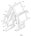
- Figure 1-3 illustrates an example of a foldable table 1 in accordance with the invention.
- the table is illustrated in the folded position in figure 1 .
- Figure 2 illustrates the same table as is illustrated in figure 1 , wherein figure 2 the table is illustrated in an intermediate position when handling the table; between folded and unfolded position, and figure 3 shows the table in the unfolded position.
- the table is rectangular and its parts are essentially symmetrically arranged in its two halves.
- the table comprises four table-top section 2a-d, which essentially form a rectangular surface in the unfolded position, two leg supports or stands 4a, 4b and a guiding rod 3 centrally arranged between the leg supports 4a, 4b and below the table-top sections 2a-d.
- Each leg support 4a, 4b comprises two legs having lateral beams in-between.
- the guiding rod 3 and the leg supports 4a, 4b are provided with a respective upper plate 6, 8a, 8b, which upper plates, together with the table-top sections 2a-d, form the surface of the table in the unfolded position.
- the table rest on the leg supports 4a, 4b and suitably also on the guide rod 3, which are mutually parallel and vertically arranged.
- the inner edges of the table-top sections 2a-d, towards the guiding rod 3, are rotatably fixed through joints 11a-b to the guiding rod.
- the outer edges of the table-top sections 2a-d, towards the inner leg supports 4a-b, are rotatably attached to the leg supports through joints 12a, b.
- the table-top sections are vertically arranged, in the folded position of the table, and horizontally arranged in the unfolded position of the table.
- the leg supports 4a, 4b are vertically arranged in both the folded as well as in the unfolded position.
- the centrally arranged guiding rod 3 is vertically arranged in both the folded as well as in the unfolded position.
- the upper plates 6, 8a-b are horizontally arranged in both the folded as well as in the unfolded position.
- the table is folded by lifting the centrally arranged guiding rod 3.
- the table-top sections 2a, b are rotated, and the inner edges follow the guiding rod 3 in its movement upwards.
- the sideways arranged leg supports are carried horizontally inwards during the folding motion together with the outer edges of the table-top sections.
- the lower portion of the guiding rod is provided with support arms 9a, 9b that are parallel to the table-top portions 2a-d and rotatably attached in their endings in the guiding rod 3 and to the leg supports 4a, 4b, one support arm 9a-b between each leg support 4a-b and the guiding rod 3.
- These support arms 9a-b holds the leg supports mutually parallel.
- the guiding rod is provided with two guide struts 5a, 5b rotatably arranged and having their inner ends in a slideable hold, in a slit or slide track 7.
- the outer ends of the guide struts are fixed by joints to a respective table-top section 2a-b.
- the table is also provided with outer table-top sections 2c, 2d that are rotatably, attached by joint to the leg supports.
- the outer table-top sections 2c, 2d are arranged outside the leg supports.
- support arms 13a, 13b are illustrated for the outer table-top sections, that are attached below, attached to and follows the movements of the inner table-top sections 2a, 2b.
- the support arms extends from the inner table-top sections 2a, 2b outwardly below and inside the outer sections 2c-d in unfolded and folded position, respectively.
- the support arms are directed down, when the inner table-top sections are horizontal, the support arms 13a-b are directed horizontally outwards and carry the outer table-top sections the horizontal direction.
- the outer sections 2c-d are illustrates in the figure as being rectangular, but can alternatively be designed in other ways and be of a semicircular or oval shape.
- the leg supports In the folded position, the storing position that is illustrated in figure 1 , the leg supports rest on the ground, such as a floor, oriented in a vertical direction and carries the table. In this position the guiding rod 3 is raised from the floor and extends vertically.
- the table-top sections 2a-d are also vertical, the inner 2a-b as well as the outer 2c-d table-top sections.
- the guiding rod 3 is raised a distance corresponding to the width of the inner table-top sections 2a-b from the guiding rod to the leg supports.
- the outer table-top sections can be longer than illustrated in the figure and extend from the stands 4a, 4b down to the floor.
- the inner table-top sections can also be longer than illustrated, for example longer than the outer table-top sections.
- the leg supports are positioned inserted in the horizontal direction towards the guide rod, their upper plates 8a, 8b, which plates are a part of the surface of the table when the table is unfolded, are directed horizontally differing from the vertically oriented table-top sections.
- the upper plates 8a-b in the leg supports 4a-b are provided with holds in the form of holes 15a-b.
- the upper plates 8a-b do not rotate when the table is unfolded and their holds move only horizontally outwardly.
- FIG 2 which also illustrates when the table is folded in, in a position between the folded and unfolded position
- the leg supports have moved horizontally outwards from the guide rod and the guiding rod has moved vertically downwards.
- the table-top sections 2a-d have been rotated to an angled position, between vertical and horizontal.
- the inner edges of the inner table-top sections 2a-b have followed the guide rod vertically downwards and the outer edges of the inner table-top sections have followed the leg supports horizontally outwards.
- the outer table-top portions which are attached to the leg supports 2a-b by means of a joint 12c-d follow the leg supports 2a-b horizontally outwards and are angled up by being lifted by the support arms 13a-b that are attached to the inner table-top sections 2a-b.
- the upper plates 8a-b are horizontal during the motion and follow the leg supports 2a-b horizontally outwards and remain in the same height during the movement.
- the direction and height of the holds, illustrated by the vertical holes 15a-b, in the upper plates remain the same.
- the upper plate 6 in the central guiding rod 3 moves downwards and is oriented horizontally all the time.
- the lower support arms 9a, 9b hold the leg supports 4a-b parallel during the movement and the guide struts 5a, 5b move vertically in a slit 7, which form a slide path, and have an upraising effect on the leg supports.
- the table-top sections are horizontal and form together with the horizontal upper plates 6, 8a-b a table surface.
- the table rests on the guiding rod 3 as well as on the leg supports 4a, 4b, which are of the same length and rest on the floor.
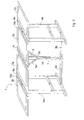
- FIG. 4 and 5 shows a table 1 in accordance with the invention, in a side view and cross section, provided with a double parasol 21.
- the double parasol 21 comprises two poles 22 that are attached to the table, by means of standing in the holes 15a, b in the upper plates 8a, 8b in the leg supports and they also stand in the lower parts of the leg supports 4a, 4b in holes 15c-f, arranged in lateral struts or beams 17a, 17b in the leg supports and in lateral foot plates 18a, 18b in the leg supports.
- both poles 22a-b of the double parasol 21 follows with the horizontal movement of the leg supports outwardly.
- the double parasol comprises an opening mechanism 24a-b in each half of the parasol.
- the illustrated mechanism comprises a downwardly directed opening struts 25a-b and opens the parasol by being brought downwards.
- An alternative is to use a double parasol having upwardly directed opening struts, which opens the parasol when they are brought upwards.
- the double parasol is provided with two wires 23a, 23b that runs inside the poles 22a-b (one in each) to a respective one of the opening mechanisms 24a-b.
- wires 23a-b are coupled to a part that moves in relation to the leg supports during the unfolding of the table, for example the guide pole 3, the opposite leg support, opposite wire, the opening mechanism of the other half of the parasol or, as is illustrated in figure 4 and in figure 5 , to a respective support arm 9a-b.
- the extension and length of the wire is adapted so that the mutual movement will pull the wire so that it unfolds the double parasol completely when the table reaches its fully unfolded position ( figure 5 ) having horizontal table-top sections. In this position the table can, and with the table the double parasol, be secured by means of the locking mechanism 14 of guide struts 5a, 5b in the slit 7 in the guiding rod 3.
- the wire is suitably lead to a wheel on an axle in the top of the parasol pole and downwards to the opening strut, so that this is pulled upwards by the wire when it is pulled and tensioned.
- the wire can be arranged on the outside of the pole.
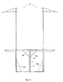
- Figure 6 illustrates a foldable table according to the invention, which comprises three leg supports 4a-c and to support rods 3a-b.
- the table in figure 6 comprises two tables 1a-b, each having two table-top sections 2a-d between two leg supports 4a-c and a guide rod arranged centrally between the leg supports, in the same way as the table in figure 1-3 .
- the two tables 1a-b have one of their two respective leg supports in common, the inner leg support 4c.
- the two tables also have outer table-top section each, outside of its respective outer table-top section 4a-b.
- this table includes three leg supports in a row with two support rods arranged between the three leg supports, and also has six table-top portions.
- the table is folded, by lifting the supports 3a-b vertically upwards in relation to the leg supports in the same way as the simpler table of figure 1 .
- the table-top surface is larger; the storing height corresponds to the storing height for the simpler table, while the table in the folded position is wider than the simpler table.
- even longer tables can be designed having leg supports and support rods alternating, wherein the leg supports are moved horizontally and the support rods are lifted vertically when the table is folded.
Landscapes
- Tables And Desks Characterized By Structural Shape (AREA)
Abstract
Description
- The invention relates to foldable tables and also to foldable tables with parasols.
- Foldable tables have been designed, for example, to casually create extra table-top surfaces during larger events and to be able to more easily stow away the table when it is no longer needed. Others have been designed for the purpose of more easily being transported. Folding the tables means that a new task has emerged when handling a table, a task that can be especially troublesome when large tables is handled by few people or only one person. A known foldable table is illustrated in publication
US 3 476 061A . - Foldable parasols and unbrellas are also previously known. They require a certain handling as well, especially if they have a large size. Larger parasols can be designed as a so called double parasol, comprising two parasol poles that carry a common oval cloth for protection against the sun. Such an oval parasol have been suitable especially for oblong, rectangular or oval tables having space for several people. A problem is that the handling of the parasol creates difficulties that grows when the size grows.
- An aim of the invention is to create a foldable table that is easy to handle. An aim is to create a table for use by a plurality of people but do not require a plurality of people to be folded. Another aim is to create a table that can be unfolded and folded in a fast and easy way. A further aim is to create a foldable table having a parasol, where the table and the parasol can be unfolded simultaneously.
- The invention provides for these purposes a foldable table comprising a first and a second table-top sections, at least two leg supports and a guiding rod centrally arranged between the leg supports, the at least two leg supports is arranged on opposite sides of the guiding rod and each one of the first and second table-top sections extends between the guiding rod and a respective one of the leg supports, each table-top section being rotatably attached to the guiding rod and its respective one of the leg supports. The table is designed so that it can be in a folded position where the table rests on the leg supports with the guiding rod vertically raised in relation to the leg supports and with the table-top sections extending vertically between the guiding rod and each respective leg support, and an unfolded position where the table rests on the leg supports having the table-top sections horizontally extended between the guiding rod and each respective leg support. The folded storing position utilises the height for storing the table-top sections och the handling can mainly be carried out by raising the guiding rod between the leg supports.
- Preferably, the two leg supports and the guiding rod have substantially the same height, and, in the unfolded position, the table rests on the leg supports and the guiding rod.
- It is preffered that the table rests on the guiding rod in the unfolded position, but an alternative is that the guiding rod is fastened against movement in another way in the unfolded position of the table, for example by means of a locking mechanism described in greater detail below.
- Preferably, the table is also provided with a first and a second supporting arm, each one of the supporting arms being arranged between the lower part of a respective leg support and the lower part of the central guiding rod, rotatably attached at each respectice leg support and at the guiding rod. The leg supports are supported by these arms so that they are kept parallel more easily, parallel to the guiding rod, and these arms also contributes to further to a fascilitated handling.
- Preferably, the table is also provided with two guide struts arranged symmetrically, each one extending between the guiding rod and a respective one of the table-top sections, the guiding struts being vertically slidable and rotatably attached to the guiding rod and rotatably attached to the respective table-top section. Hereby the vertical orientation of the leg supports is maintained during handling of the table. These guide struts can preferably be fixed by a locking mechanism that prevents the vertical movement of the guiding rod, so that the table and the guiding rod kan be locked in the position of use. Other parts of the table can also be adapted for mutual interlocking, as a complement or as an alternativer to the locking of the guide struts to the guiding rod.
- The foldable table is preferably also provided with upper horisontal plates in each one of the leg supports, which horisontal plates create a table top together with the table-top sections in the unfolded position of the table. In contrast to the table-top sections, the horizontal plates are always horisontal, also in the folded storage position. Each of these upper horisontal plates preferably comprises a support for, for example, a parasol pole. Since they are attached to the leg supports and moves horizontally without rotation during handling of the table, one and the same parasol can stand upright in the plate in the folded as well as in the unforlded position and during the handling between these positions. Moreover the horizontal movement of the leg supports and thereby also the movement of parasol poles can be used for opening, for example, a double parasol. This can, e.g., be provided by connecting a wire or rope between the opening mechanisms in the two halves of the double parasol, so that this wire or rope is tensioned and opens the halves of the parasol when the parasol poles and the leg supports are moved simultaneously horizontally away from each other when the table is unfolded.
- The invention also provides an arrangement of a foldable table and a double parasol, where the table and the double parasol can be unfolded simultaneously. This is achieved by attaching the double parasol to leg supports of the table, which leg supports and thereby also the parasol poles, moves in relation to each other when the table is put in place and by means of the interconnection of the opening mechanisms of the double parasol and use the relative movement for manoeuvring the opening mechanisms.
- Preferably, the double parasol comprises two poles, each one of which is attached to a respective one of the leg supports.
-
-
Figure 1 illustrates a foldable table in accordance with the invention in a side view in a folded position. -
Figure 2 illustrates the table offigure 1 being unfolded. -
Figure 3 illustrates the table unfolded for use. -
Figure 4 illustrates the table provided with a double parasol. -
Figure 5 illustrates the table and the double parasol unfolded. -
Figure 6 illustrates a larger embodiment of the table in accordance with the invention. -
Figure 1-3 illustrates an example of a foldable table 1 in accordance with the invention. The table is illustrated in the folded position infigure 1 .Figure 2 illustrates the same table as is illustrated infigure 1 , whereinfigure 2 the table is illustrated in an intermediate position when handling the table; between folded and unfolded position, andfigure 3 shows the table in the unfolded position. The table is rectangular and its parts are essentially symmetrically arranged in its two halves. - The table comprises four table-
top section 2a-d, which essentially form a rectangular surface in the unfolded position, two leg supports or stands 4a, 4b and a guidingrod 3 centrally arranged between the leg supports 4a, 4b and below the table-top sections 2a-d. Eachleg support rod 3 and the leg supports 4a, 4b are provided with a respectiveupper plate top sections 2a-d, form the surface of the table in the unfolded position. In the unfolded position the table rest on the leg supports 4a, 4b and suitably also on theguide rod 3, which are mutually parallel and vertically arranged. The inner edges of the table-top sections 2a-d, towards the guidingrod 3, are rotatably fixed throughjoints 11a-b to the guiding rod. The outer edges of the table-top sections 2a-d, towards the inner leg supports 4a-b, are rotatably attached to the leg supports throughjoints 12a, b. The table-top sections are vertically arranged, in the folded position of the table, and horizontally arranged in the unfolded position of the table. The leg supports 4a, 4b are vertically arranged in both the folded as well as in the unfolded position. The centrally arranged guidingrod 3 is vertically arranged in both the folded as well as in the unfolded position. Theupper plates rod 3. When the table is manoeuvred from the unfolded to the folded position, the table-top sections 2a, b are rotated, and the inner edges follow the guidingrod 3 in its movement upwards. The sideways arranged leg supports are carried horizontally inwards during the folding motion together with the outer edges of the table-top sections. - The lower portion of the guiding rod is provided with
support arms top portions 2a-d and rotatably attached in their endings in the guidingrod 3 and to the leg supports 4a, 4b, onesupport arm 9a-b between eachleg support 4a-b and the guidingrod 3. These supportarms 9a-b holds the leg supports mutually parallel. For facilitating maintaining the led supports 4a-b vertical during manoeuvring the table, the guiding rod is provided with twoguide struts slide track 7. The outer ends of the guide struts are fixed by joints to a respective table-top section 2a-b. - The table is also provided with outer table-
top sections top sections figure 2 , support arms 13a, 13b are illustrated for the outer table-top sections, that are attached below, attached to and follows the movements of the inner table-top sections top sections outer sections 2c-d in unfolded and folded position, respectively. When the inner table-top sections are vertical, the support arms are directed down, when the inner table-top sections are horizontal, the support arms 13a-b are directed horizontally outwards and carry the outer table-top sections the horizontal direction. Theouter sections 2c-d are illustrates in the figure as being rectangular, but can alternatively be designed in other ways and be of a semicircular or oval shape. - In the folded position, the storing position that is illustrated in
figure 1 , the leg supports rest on the ground, such as a floor, oriented in a vertical direction and carries the table. In this position the guidingrod 3 is raised from the floor and extends vertically. The table-top sections 2a-d are also vertical, the inner 2a-b as well as the outer 2c-d table-top sections. The guidingrod 3 is raised a distance corresponding to the width of the inner table-top sections 2a-b from the guiding rod to the leg supports. The outer table-top sections can be longer than illustrated in the figure and extend from thestands upper plates upper plates 8a-b in the leg supports 4a-b are provided with holds in the form ofholes 15a-b. Theupper plates 8a-b do not rotate when the table is unfolded and their holds move only horizontally outwardly. - When the table is unfolded, as in
figure 2 , which also illustrates when the table is folded in, in a position between the folded and unfolded position, the leg supports have moved horizontally outwards from the guide rod and the guiding rod has moved vertically downwards. The table-top sections 2a-d have been rotated to an angled position, between vertical and horizontal. The inner edges of the inner table-top sections 2a-b have followed the guide rod vertically downwards and the outer edges of the inner table-top sections have followed the leg supports horizontally outwards. The outer table-top portions, which are attached to the leg supports 2a-b by means of a joint 12c-d follow the leg supports 2a-b horizontally outwards and are angled up by being lifted by the support arms 13a-b that are attached to the inner table-top sections 2a-b. - The
upper plates 8a-b are horizontal during the motion and follow the leg supports 2a-b horizontally outwards and remain in the same height during the movement. The direction and height of the holds, illustrated by thevertical holes 15a-b, in the upper plates remain the same. Theupper plate 6 in thecentral guiding rod 3 moves downwards and is oriented horizontally all the time. - The
lower support arms slit 7, which form a slide path, and have an upraising effect on the leg supports. - In the unfolded position, the use position in accordance with
figure 3 , the table-top sections are horizontal and form together with the horizontalupper plates rod 3 as well as on the leg supports 4a, 4b, which are of the same length and rest on the floor. -
Figure 4 and5 shows a table 1 in accordance with the invention, in a side view and cross section, provided with adouble parasol 21. Thedouble parasol 21 comprises twopoles 22 that are attached to the table, by means of standing in theholes 15a, b in theupper plates beams lateral foot plates - When the table is unfolded, both poles 22a-b of the
double parasol 21 follows with the horizontal movement of the leg supports outwardly. The double parasol comprises anopening mechanism 24a-b in each half of the parasol. The illustrated mechanism comprises a downwardly directed opening struts 25a-b and opens the parasol by being brought downwards. An alternative is to use a double parasol having upwardly directed opening struts, which opens the parasol when they are brought upwards. To open the double parasol, the double parasol is provided with twowires mechanisms 24a-b. Thesewires 23a-b are coupled to a part that moves in relation to the leg supports during the unfolding of the table, for example theguide pole 3, the opposite leg support, opposite wire, the opening mechanism of the other half of the parasol or, as is illustrated infigure 4 and infigure 5 , to arespective support arm 9a-b. The extension and length of the wire is adapted so that the mutual movement will pull the wire so that it unfolds the double parasol completely when the table reaches its fully unfolded position (figure 5 ) having horizontal table-top sections. In this position the table can, and with the table the double parasol, be secured by means of thelocking mechanism 14 of guide struts 5a, 5b in theslit 7 in the guidingrod 3. In the case with parasols having opening struts that are brought upwards along the parasol pole, the wire is suitably lead to a wheel on an axle in the top of the parasol pole and downwards to the opening strut, so that this is pulled upwards by the wire when it is pulled and tensioned. Also as an alternative to being lead inside the pole, the wire can be arranged on the outside of the pole. -
Figure 6 illustrates a foldable table according to the invention, which comprises three leg supports 4a-c and to supportrods 3a-b. The table infigure 6 comprises two tables 1a-b, each having two table-top sections 2a-d between two leg supports 4a-c and a guide rod arranged centrally between the leg supports, in the same way as the table infigure 1-3 . The two tables 1a-b have one of their two respective leg supports in common, theinner leg support 4c. The two tables also have outer table-top section each, outside of its respective outer table-top section 4a-b. Thus, this table includes three leg supports in a row with two support rods arranged between the three leg supports, and also has six table-top portions. The table is folded, by lifting thesupports 3a-b vertically upwards in relation to the leg supports in the same way as the simpler table offigure 1 . Thereby the table-top surface is larger; the storing height corresponds to the storing height for the simpler table, while the table in the folded position is wider than the simpler table. Similarly, even longer tables can be designed having leg supports and support rods alternating, wherein the leg supports are moved horizontally and the support rods are lifted vertically when the table is folded.
Claims (7)
- Foldable table comprising a first and a second table-top sections (2a, b), two leg supports (4a, 4b) and a guiding rod (3), the at least two leg supports (4a, 4b) is arranged on opposite sides of the guiding rod (3) and each one of the first and second table-top sections (2a, 2b) extends between the guiding rod (3) and a respective one of the leg supports (4a, 4b), each table-top section being rotatably attached to the guiding rod (3) and its respective one of the leg supports (4a, 4b), so that the table can be in a folded position where the table rests on the leg supports with the guiding rod vertically raised in relation to the leg supports and with the table-top sections extending vertically between the guiding rod and each respective leg support, and an unfolded position where the table rests on the leg supports (4a, 4b) and with the table-top sections horizontally extended between the guiding rod and each respective leg support, characterised in that each one of the leg supports (4a, 4b) comprises an upper horizontal plate (8a, 8b), which create a table top together with the table-top sections in the unfolded position of the table, and each upper horizontal plate comprises a socket (15a, 15b) for a parasol pole.
- Foldable table according to claim 1, wherein each of the two leg supports (4a, 4b) and the guiding rod (3) have substantially the same height, and the table in the unfolded position, rests on the leg supports (4a, 4b) and the guiding rod(3).
- Foldable table according to claims 1 or 2, provided with a first and a second supporting arm (9a, 9b), each of the supporting arms being arranged between the lower part of a respective leg support (4a, 4b) and the lower part of the central guiding rod (3), rotatably attached at each respective leg support and the guiding rod.
- Foldable table according to any of claims 1 to 3, comprising a first and a second guide strut (5a, 5b) extending between the guiding rod (3) and a respective one of the table-top sections (2a, 2b) vertically slidable and rotatably attached to the guiding rod (3) and rotatably attached to the respective table-top section (2a, 2b).
- Foldable table according to claim 4 comprising at least one locking mechanism (14) for locking the vertical movements of the guide struts (5a, 5b) at the guide rod.
- Foldable table construction comprising two foldable tables according to claim 1, which two foldable tables share one (4c) of their leg supports.
- Arrangement comprising a foldable table (1) according to any of claims 1-6, characterised in that the arrangement also comprises a double parasol (21) having means (23-35) for unfolding the parasol, which means are coupled to the table so that unfolding the table unfolds the parasol simultaneously.
Applications Claiming Priority (1)
| Application Number | Priority Date | Filing Date | Title |
|---|---|---|---|
| SE0850072A SE533117C2 (en) | 2008-11-11 | 2008-11-11 | Folding table |
Publications (2)
| Publication Number | Publication Date |
|---|---|
| EP2183993A1 EP2183993A1 (en) | 2010-05-12 |
| EP2183993B1 true EP2183993B1 (en) | 2012-01-18 |
Family
ID=41395583
Family Applications (1)
| Application Number | Title | Priority Date | Filing Date |
|---|---|---|---|
| EP09175667A Not-in-force EP2183993B1 (en) | 2008-11-11 | 2009-11-11 | Foldable table |
Country Status (4)
| Country | Link |
|---|---|
| US (1) | US8196529B2 (en) |
| EP (1) | EP2183993B1 (en) |
| AT (1) | ATE541476T1 (en) |
| SE (1) | SE533117C2 (en) |
Families Citing this family (11)
| Publication number | Priority date | Publication date | Assignee | Title |
|---|---|---|---|---|
| FR2935947B1 (en) * | 2008-09-18 | 2010-12-17 | Sncf | TABLE INTENDED TO BE AGENCED IN A RAILWAY VEHICLE FOR TRAVELERS. |
| US20100252514A1 (en) * | 2009-04-03 | 2010-10-07 | Min-Ju Chung | Foldable baseball equipment rack |
| TWM390716U (en) * | 2009-12-30 | 2010-10-21 | Shyh Geng Enterprise Co Ltd | Foldable storage rack |
| CN202077847U (en) * | 2011-01-07 | 2011-12-21 | 吴健中 | Folding frame capable of vertically lifting and sliding |
| CA2784048A1 (en) * | 2012-07-27 | 2014-01-27 | Jean-Marc Landry | Foldable unit, foldable system, fabrication methods and uses thereof |
| DE202013005789U1 (en) | 2013-06-27 | 2013-07-30 | MFG Mecklenburger Freizeitmöbel GmbH | Folding leisure and garden table |
| DE202013005787U1 (en) | 2013-06-27 | 2013-08-28 | MFG Mecklenburger Freizeitmöbel GmbH | Folding garden and leisure table |
| US10441070B2 (en) * | 2017-08-08 | 2019-10-15 | Dorel Home Furnishings, Inc. | Compactable utility table |
| US10485332B2 (en) * | 2018-03-21 | 2019-11-26 | Kustom Seating Unlimited, Inc. | Locking mechanism for a table |
| TWI664937B (en) * | 2018-08-31 | 2019-07-11 | 公隆實業股份有限公司 | Variable activity table |
| CN109090825B (en) * | 2018-09-30 | 2021-10-15 | 肖泽恒 | Extension table |
Family Cites Families (18)
| Publication number | Priority date | Publication date | Assignee | Title |
|---|---|---|---|---|
| US586112A (en) * | 1897-07-13 | Island | ||
| GB286458A (en) | 1927-03-09 | 1928-03-08 | Harry Jackson Crossley | Improvements in connection with folding or collapsible tables, waggons, shelves or the like |
| US1828780A (en) * | 1927-11-15 | 1931-10-27 | Troy Laundry Machinery Co Inc | Collapsible conveyer |
| US2764460A (en) | 1954-04-19 | 1956-09-25 | Reynold R Erickson | Folding sectional table |
| US2781525A (en) | 1955-03-07 | 1957-02-19 | Gendron Wheel Company | Collapsible stretcher |
| US2782085A (en) * | 1955-12-05 | 1957-02-19 | Louis Cooper | Collapsible table |
| US2913294A (en) * | 1956-11-08 | 1959-11-17 | Leonard J Linde | Collapsible table employing legs for supporting the table in extended and collapsed positions |
| US3006705A (en) * | 1957-10-14 | 1961-10-31 | Williams Billy Oliver | Combination table, sand box or wading pool |
| US3101062A (en) * | 1961-09-18 | 1963-08-20 | Hamilton Mfg Co | Folding table and bench constructions |
| US3351029A (en) * | 1965-11-22 | 1967-11-07 | Sico Inc | Folding stage construction |
| US3476061A (en) | 1967-12-28 | 1969-11-04 | Sasuke Takahashi | Folding table |
| US3511532A (en) * | 1968-02-05 | 1970-05-12 | American Hospital Supply Corp | Folding table with seats |
| CH661420A5 (en) * | 1983-04-11 | 1987-07-31 | Hansrudolf Zollinger | Collapsible table. |
| US4740010A (en) * | 1987-01-09 | 1988-04-26 | Accurate Metal Products, Inc. | Foldable cart |
| US5215108A (en) * | 1991-04-09 | 1993-06-01 | Sprague John V | Table and canopy apparatus |
| US7101000B2 (en) * | 2003-08-13 | 2006-09-05 | Original Ideas, Inc. | Portable bar with advertising materials |
| US6866054B1 (en) * | 2003-12-24 | 2005-03-15 | Judith E Collins | Portable table top tent |
| US8205937B2 (en) * | 2009-05-29 | 2012-06-26 | Amtab Manufacturing Corporation | Mobile folding table with high-speed cylinder lift-assist and stabilizer mechanism |
-
2008
- 2008-11-11 SE SE0850072A patent/SE533117C2/en not_active IP Right Cessation
-
2009
- 2009-11-11 AT AT09175667T patent/ATE541476T1/en active
- 2009-11-11 US US12/616,632 patent/US8196529B2/en not_active Expired - Fee Related
- 2009-11-11 EP EP09175667A patent/EP2183993B1/en not_active Not-in-force
Also Published As
| Publication number | Publication date |
|---|---|
| ATE541476T1 (en) | 2012-02-15 |
| EP2183993A1 (en) | 2010-05-12 |
| US8196529B2 (en) | 2012-06-12 |
| US20100116176A1 (en) | 2010-05-13 |
| SE0850072A1 (en) | 2010-05-12 |
| SE533117C2 (en) | 2010-06-29 |
Similar Documents
| Publication | Publication Date | Title |
|---|---|---|
| EP2183993B1 (en) | Foldable table | |
| US8701692B2 (en) | Collapsible portable shelter | |
| AU2010203041B2 (en) | Canopy Frame | |
| US20160008070A1 (en) | Expandable and foldable mayo stand | |
| US9828788B2 (en) | Canopy framework with locking cam lever | |
| CN103458740A (en) | Vertically-elevating sliding foldable frame | |
| US10155527B2 (en) | Stackable trusses for transport and support of appliances | |
| US9901149B2 (en) | Canopies and canopy support structures | |
| CN101141899A (en) | Folding table | |
| AU2006207858B2 (en) | Shading apparatus | |
| JP2020523503A (en) | Portable stage system | |
| JP2015105544A (en) | Collapsible high place work platform | |
| CN107048833B (en) | Travelling bed | |
| EP1518476A1 (en) | Portable folding suspended bed | |
| CN105877154A (en) | Multifunctional folding table | |
| JP6469997B2 (en) | Tent frame | |
| KR200482801Y1 (en) | Folding tent frame | |
| CN112386044B (en) | Bedstead | |
| WO2011117658A1 (en) | Cot | |
| JP2005082352A (en) | Tower crane | |
| CN107989463B (en) | Temporary medical tent | |
| CN202959424U (en) | Easy-folding foldable frame | |
| JPH02117591A (en) | Foldable crane having boom comprising two or three elements connected mutually | |
| US20140213393A1 (en) | Table tennis table | |
| GB2438266A (en) | Access tower |
Legal Events
| Date | Code | Title | Description |
|---|---|---|---|
| PUAI | Public reference made under article 153(3) epc to a published international application that has entered the european phase |
Free format text: ORIGINAL CODE: 0009012 |
|
| AK | Designated contracting states |
Kind code of ref document: A1 Designated state(s): AT BE BG CH CY CZ DE DK EE ES FI FR GB GR HR HU IE IS IT LI LT LU LV MC MK MT NL NO PL PT RO SE SI SK SM TR |
|
| AX | Request for extension of the european patent |
Extension state: AL BA RS |
|
| 17P | Request for examination filed |
Effective date: 20101101 |
|
| GRAP | Despatch of communication of intention to grant a patent |
Free format text: ORIGINAL CODE: EPIDOSNIGR1 |
|
| GRAS | Grant fee paid |
Free format text: ORIGINAL CODE: EPIDOSNIGR3 |
|
| GRAA | (expected) grant |
Free format text: ORIGINAL CODE: 0009210 |
|
| AK | Designated contracting states |
Kind code of ref document: B1 Designated state(s): AT BE BG CH CY CZ DE DK EE ES FI FR GB GR HR HU IE IS IT LI LT LU LV MC MK MT NL NO PL PT RO SE SI SK SM TR |
|
| REG | Reference to a national code |
Ref country code: GB Ref legal event code: FG4D |
|
| REG | Reference to a national code |
Ref country code: CH Ref legal event code: EP |
|
| REG | Reference to a national code |
Ref country code: IE Ref legal event code: FG4D Ref country code: AT Ref legal event code: REF Ref document number: 541476 Country of ref document: AT Kind code of ref document: T Effective date: 20120215 |
|
| REG | Reference to a national code |
Ref country code: DE Ref legal event code: R096 Ref document number: 602009004724 Country of ref document: DE Effective date: 20120322 |
|
| REG | Reference to a national code |
Ref country code: NL Ref legal event code: VDEP Effective date: 20120118 |
|
| LTIE | Lt: invalidation of european patent or patent extension |
Effective date: 20120118 |
|
| PG25 | Lapsed in a contracting state [announced via postgrant information from national office to epo] |
Ref country code: LT Free format text: LAPSE BECAUSE OF FAILURE TO SUBMIT A TRANSLATION OF THE DESCRIPTION OR TO PAY THE FEE WITHIN THE PRESCRIBED TIME-LIMIT Effective date: 20120118 Ref country code: BG Free format text: LAPSE BECAUSE OF FAILURE TO SUBMIT A TRANSLATION OF THE DESCRIPTION OR TO PAY THE FEE WITHIN THE PRESCRIBED TIME-LIMIT Effective date: 20120418 Ref country code: BE Free format text: LAPSE BECAUSE OF FAILURE TO SUBMIT A TRANSLATION OF THE DESCRIPTION OR TO PAY THE FEE WITHIN THE PRESCRIBED TIME-LIMIT Effective date: 20120118 Ref country code: HR Free format text: LAPSE BECAUSE OF FAILURE TO SUBMIT A TRANSLATION OF THE DESCRIPTION OR TO PAY THE FEE WITHIN THE PRESCRIBED TIME-LIMIT Effective date: 20120118 Ref country code: IS Free format text: LAPSE BECAUSE OF FAILURE TO SUBMIT A TRANSLATION OF THE DESCRIPTION OR TO PAY THE FEE WITHIN THE PRESCRIBED TIME-LIMIT Effective date: 20120518 Ref country code: NO Free format text: LAPSE BECAUSE OF FAILURE TO SUBMIT A TRANSLATION OF THE DESCRIPTION OR TO PAY THE FEE WITHIN THE PRESCRIBED TIME-LIMIT Effective date: 20120418 Ref country code: NL Free format text: LAPSE BECAUSE OF FAILURE TO SUBMIT A TRANSLATION OF THE DESCRIPTION OR TO PAY THE FEE WITHIN THE PRESCRIBED TIME-LIMIT Effective date: 20120118 |
|
| PG25 | Lapsed in a contracting state [announced via postgrant information from national office to epo] |
Ref country code: PT Free format text: LAPSE BECAUSE OF FAILURE TO SUBMIT A TRANSLATION OF THE DESCRIPTION OR TO PAY THE FEE WITHIN THE PRESCRIBED TIME-LIMIT Effective date: 20120518 Ref country code: FI Free format text: LAPSE BECAUSE OF FAILURE TO SUBMIT A TRANSLATION OF THE DESCRIPTION OR TO PAY THE FEE WITHIN THE PRESCRIBED TIME-LIMIT Effective date: 20120118 Ref country code: PL Free format text: LAPSE BECAUSE OF FAILURE TO SUBMIT A TRANSLATION OF THE DESCRIPTION OR TO PAY THE FEE WITHIN THE PRESCRIBED TIME-LIMIT Effective date: 20120118 Ref country code: GR Free format text: LAPSE BECAUSE OF FAILURE TO SUBMIT A TRANSLATION OF THE DESCRIPTION OR TO PAY THE FEE WITHIN THE PRESCRIBED TIME-LIMIT Effective date: 20120419 Ref country code: LV Free format text: LAPSE BECAUSE OF FAILURE TO SUBMIT A TRANSLATION OF THE DESCRIPTION OR TO PAY THE FEE WITHIN THE PRESCRIBED TIME-LIMIT Effective date: 20120118 |
|
| REG | Reference to a national code |
Ref country code: AT Ref legal event code: MK05 Ref document number: 541476 Country of ref document: AT Kind code of ref document: T Effective date: 20120118 |
|
| PG25 | Lapsed in a contracting state [announced via postgrant information from national office to epo] |
Ref country code: CY Free format text: LAPSE BECAUSE OF FAILURE TO SUBMIT A TRANSLATION OF THE DESCRIPTION OR TO PAY THE FEE WITHIN THE PRESCRIBED TIME-LIMIT Effective date: 20120118 |
|
| PG25 | Lapsed in a contracting state [announced via postgrant information from national office to epo] |
Ref country code: CZ Free format text: LAPSE BECAUSE OF FAILURE TO SUBMIT A TRANSLATION OF THE DESCRIPTION OR TO PAY THE FEE WITHIN THE PRESCRIBED TIME-LIMIT Effective date: 20120118 Ref country code: EE Free format text: LAPSE BECAUSE OF FAILURE TO SUBMIT A TRANSLATION OF THE DESCRIPTION OR TO PAY THE FEE WITHIN THE PRESCRIBED TIME-LIMIT Effective date: 20120118 Ref country code: SI Free format text: LAPSE BECAUSE OF FAILURE TO SUBMIT A TRANSLATION OF THE DESCRIPTION OR TO PAY THE FEE WITHIN THE PRESCRIBED TIME-LIMIT Effective date: 20120118 Ref country code: SE Free format text: LAPSE BECAUSE OF FAILURE TO SUBMIT A TRANSLATION OF THE DESCRIPTION OR TO PAY THE FEE WITHIN THE PRESCRIBED TIME-LIMIT Effective date: 20120118 Ref country code: DK Free format text: LAPSE BECAUSE OF FAILURE TO SUBMIT A TRANSLATION OF THE DESCRIPTION OR TO PAY THE FEE WITHIN THE PRESCRIBED TIME-LIMIT Effective date: 20120118 Ref country code: RO Free format text: LAPSE BECAUSE OF FAILURE TO SUBMIT A TRANSLATION OF THE DESCRIPTION OR TO PAY THE FEE WITHIN THE PRESCRIBED TIME-LIMIT Effective date: 20120118 |
|
| PLBE | No opposition filed within time limit |
Free format text: ORIGINAL CODE: 0009261 |
|
| STAA | Information on the status of an ep patent application or granted ep patent |
Free format text: STATUS: NO OPPOSITION FILED WITHIN TIME LIMIT |
|
| PG25 | Lapsed in a contracting state [announced via postgrant information from national office to epo] |
Ref country code: SK Free format text: LAPSE BECAUSE OF FAILURE TO SUBMIT A TRANSLATION OF THE DESCRIPTION OR TO PAY THE FEE WITHIN THE PRESCRIBED TIME-LIMIT Effective date: 20120118 Ref country code: IT Free format text: LAPSE BECAUSE OF FAILURE TO SUBMIT A TRANSLATION OF THE DESCRIPTION OR TO PAY THE FEE WITHIN THE PRESCRIBED TIME-LIMIT Effective date: 20120118 |
|
| 26N | No opposition filed |
Effective date: 20121019 |
|
| PG25 | Lapsed in a contracting state [announced via postgrant information from national office to epo] |
Ref country code: AT Free format text: LAPSE BECAUSE OF FAILURE TO SUBMIT A TRANSLATION OF THE DESCRIPTION OR TO PAY THE FEE WITHIN THE PRESCRIBED TIME-LIMIT Effective date: 20120118 |
|
| REG | Reference to a national code |
Ref country code: DE Ref legal event code: R097 Ref document number: 602009004724 Country of ref document: DE Effective date: 20121019 |
|
| PG25 | Lapsed in a contracting state [announced via postgrant information from national office to epo] |
Ref country code: ES Free format text: LAPSE BECAUSE OF FAILURE TO SUBMIT A TRANSLATION OF THE DESCRIPTION OR TO PAY THE FEE WITHIN THE PRESCRIBED TIME-LIMIT Effective date: 20120429 |
|
| REG | Reference to a national code |
Ref country code: IE Ref legal event code: MM4A |
|
| PG25 | Lapsed in a contracting state [announced via postgrant information from national office to epo] |
Ref country code: IE Free format text: LAPSE BECAUSE OF NON-PAYMENT OF DUE FEES Effective date: 20121111 |
|
| PG25 | Lapsed in a contracting state [announced via postgrant information from national office to epo] |
Ref country code: MT Free format text: LAPSE BECAUSE OF FAILURE TO SUBMIT A TRANSLATION OF THE DESCRIPTION OR TO PAY THE FEE WITHIN THE PRESCRIBED TIME-LIMIT Effective date: 20120118 |
|
| PG25 | Lapsed in a contracting state [announced via postgrant information from national office to epo] |
Ref country code: TR Free format text: LAPSE BECAUSE OF FAILURE TO SUBMIT A TRANSLATION OF THE DESCRIPTION OR TO PAY THE FEE WITHIN THE PRESCRIBED TIME-LIMIT Effective date: 20120118 Ref country code: MC Free format text: LAPSE BECAUSE OF NON-PAYMENT OF DUE FEES Effective date: 20121130 |
|
| PG25 | Lapsed in a contracting state [announced via postgrant information from national office to epo] |
Ref country code: SM Free format text: LAPSE BECAUSE OF FAILURE TO SUBMIT A TRANSLATION OF THE DESCRIPTION OR TO PAY THE FEE WITHIN THE PRESCRIBED TIME-LIMIT Effective date: 20120118 Ref country code: LU Free format text: LAPSE BECAUSE OF NON-PAYMENT OF DUE FEES Effective date: 20121111 |
|
| REG | Reference to a national code |
Ref country code: CH Ref legal event code: PL |
|
| PG25 | Lapsed in a contracting state [announced via postgrant information from national office to epo] |
Ref country code: CH Free format text: LAPSE BECAUSE OF NON-PAYMENT OF DUE FEES Effective date: 20131130 Ref country code: HU Free format text: LAPSE BECAUSE OF FAILURE TO SUBMIT A TRANSLATION OF THE DESCRIPTION OR TO PAY THE FEE WITHIN THE PRESCRIBED TIME-LIMIT Effective date: 20091111 Ref country code: LI Free format text: LAPSE BECAUSE OF NON-PAYMENT OF DUE FEES Effective date: 20131130 |
|
| PG25 | Lapsed in a contracting state [announced via postgrant information from national office to epo] |
Ref country code: MK Free format text: LAPSE BECAUSE OF FAILURE TO SUBMIT A TRANSLATION OF THE DESCRIPTION OR TO PAY THE FEE WITHIN THE PRESCRIBED TIME-LIMIT Effective date: 20120118 |
|
| REG | Reference to a national code |
Ref country code: FR Ref legal event code: PLFP Year of fee payment: 7 |
|
| PGFP | Annual fee paid to national office [announced via postgrant information from national office to epo] |
Ref country code: DE Payment date: 20151117 Year of fee payment: 7 Ref country code: GB Payment date: 20151123 Year of fee payment: 7 |
|
| PGFP | Annual fee paid to national office [announced via postgrant information from national office to epo] |
Ref country code: FR Payment date: 20151130 Year of fee payment: 7 |
|
| REG | Reference to a national code |
Ref country code: DE Ref legal event code: R119 Ref document number: 602009004724 Country of ref document: DE |
|
| GBPC | Gb: european patent ceased through non-payment of renewal fee |
Effective date: 20161111 |
|
| REG | Reference to a national code |
Ref country code: FR Ref legal event code: ST Effective date: 20170731 |
|
| PG25 | Lapsed in a contracting state [announced via postgrant information from national office to epo] |
Ref country code: FR Free format text: LAPSE BECAUSE OF NON-PAYMENT OF DUE FEES Effective date: 20161130 |
|
| PG25 | Lapsed in a contracting state [announced via postgrant information from national office to epo] |
Ref country code: DE Free format text: LAPSE BECAUSE OF NON-PAYMENT OF DUE FEES Effective date: 20170601 Ref country code: GB Free format text: LAPSE BECAUSE OF NON-PAYMENT OF DUE FEES Effective date: 20161111 |