EP2183952A1 - Säherz und Einzelkornsämaschine - Google Patents
Säherz und Einzelkornsämaschine Download PDFInfo
- Publication number
- EP2183952A1 EP2183952A1 EP09013943A EP09013943A EP2183952A1 EP 2183952 A1 EP2183952 A1 EP 2183952A1 EP 09013943 A EP09013943 A EP 09013943A EP 09013943 A EP09013943 A EP 09013943A EP 2183952 A1 EP2183952 A1 EP 2183952A1
- Authority
- EP
- European Patent Office
- Prior art keywords
- seed
- disc
- heart
- sowing
- spring
- Prior art date
- Legal status (The legal status is an assumption and is not a legal conclusion. Google has not performed a legal analysis and makes no representation as to the accuracy of the status listed.)
- Granted
Links
- 238000009331 sowing Methods 0.000 claims description 19
- 238000005192 partition Methods 0.000 claims description 18
- 238000003860 storage Methods 0.000 claims description 10
- 238000010899 nucleation Methods 0.000 claims description 8
- 241000238370 Sepia Species 0.000 claims 1
- 108010016634 Seed Storage Proteins Proteins 0.000 description 6
- 238000004519 manufacturing process Methods 0.000 description 5
- 239000002689 soil Substances 0.000 description 3
- 238000005299 abrasion Methods 0.000 description 2
- 230000005540 biological transmission Effects 0.000 description 2
- 239000013013 elastic material Substances 0.000 description 2
- 238000007789 sealing Methods 0.000 description 2
- 230000004308 accommodation Effects 0.000 description 1
- 230000006978 adaptation Effects 0.000 description 1
- 238000011161 development Methods 0.000 description 1
- 230000018109 developmental process Effects 0.000 description 1
- 239000003337 fertilizer Substances 0.000 description 1
- 230000000284 resting effect Effects 0.000 description 1
- 238000000926 separation method Methods 0.000 description 1
- 230000007704 transition Effects 0.000 description 1
- 235000013311 vegetables Nutrition 0.000 description 1
Images


Classifications
-
- A—HUMAN NECESSITIES
- A01—AGRICULTURE; FORESTRY; ANIMAL HUSBANDRY; HUNTING; TRAPPING; FISHING
- A01C—PLANTING; SOWING; FERTILISING
- A01C7/00—Sowing
- A01C7/04—Single-grain seeders with or without suction devices
- A01C7/042—Single-grain seeders with or without suction devices using pneumatic means
- A01C7/044—Pneumatic seed wheels
- A01C7/046—Pneumatic seed wheels with perforated seeding discs
Definitions
- the invention relates to a sowing heart according to claim 1 and a precision seed drill according to claim 8.
- Such precision seeders usually have a plurality of presekarn with a variety of preseherzen.
- Known sheherzen for pneumatic Einzelkornsäaggregate usually consist of two halves, namely a rear part, in which the storage of the seed disc and the negative pressure area are housed and a front part, in which the lower outlet of the seed hopper opens and which itself has a seed storage.
- the seed disc forms a partition to the negative pressure area and a partition wall of the seed storage.
- Object of the present invention is therefore to provide an easy-to-use clutch, which is cheaper to manufacture and whose components are as simple and flexible interchangeable.
- the basic idea of the present invention is to make the seed disc of the seed ore at least partially infinitely adjustable in the axial direction by means of an actuating device acting in the axial direction relative to the dividing wall of the seed storage. This is achieved in particular by providing a flange acted upon by an actuator on the axis / drive shaft of the poleherzes, which is biased by a clamping element relative to the actuator. Actuator, flange and clamping element are components of the actuator.
- the seed disc is axially adjustable or adjustable, preferably in one, on an axially mounted on the axis / drive shaft of the seed disc flange, which is identical to or formed by the above flange by an actuator, in particular a nut small but exact adjustment range of preferably less than 1 mm, more preferably less than 0.5 mm.
- the flange is prestressed from its rear side by the clamping element and receives the seeding disc on its front side so that it can not rotate.
- this design allows adjustment of the axial distance between partition and seeder without removing the seed disc.
- a partition wall plane formed by the partition wall is parallel to a scalenebene formed by the seeding disc, wherein the scalenebene is formed parallelverschietons by the adjusting device with respect to the partition wall plane.
- the gap between the partition and rotatable working efficiency by the actuator within the manufacturing accuracies with advantage to a minimum, preferably reduced to zero, without the operation of the stylherzes by friction between partition and seeding a major abrasion.
- the contact pressure of the seed disc on the partition is to be reduced in an advantageous manner within the manufacturing accuracies also to a minimum, in particular to zero.
- the embodiment of the invention has the advantage that the seed is not drawn between the partition and sowing disc and the expensive seed uncontrollably reaches the soil or even destroyed.
- fertilizers for example, fertilizers, seeds, whether pilled or naked, can be subsumed.
- the sowing disc By, in particular with little spring travel, spring-loaded storage of the rotating sowing disc, the sowing disc is positioned exactly opposite the partition, so that the storage section with the seed storage and the transport / discharge section optimally separated, in particular sealed, and even small seed over a long period of sheherzes remains without loss in the storage section.
- the adjusting device on a clamping element in particular a spring, preferably a flat spring, more preferably a plate spring, for acting on the seed disc against an actuator of the actuating device. Due to the flat shape of a disc spring and the defined and high power transmission of a plate spring optimal implementation of the requirements for the clamping element allows, namely a space-saving accommodation below the sowing disc with a small spring stroke or travel.
- the clamping element is rotatable together with the sowing disc, so that a mutual removal is avoided as possible.
- the clamping element is advantageously arranged on a drive shaft for rotation of the seed disc, since this results in an optimal distribution of force due to the centric arrangement of the clamping element.
- Particularly advantageous is the combination with the disc spring described above.
- the clamping element and the flange in one piece from an elastic material, the corresponding spring properties, for example according to the plate spring, has.
- the flange made of plastic, for example PA6 be formed with an introduced in the center of the flange elastic material, such as PU.
- FIGS. 1a and 1b a sowing unit 1 of a precision seed drill according to the invention is shown, which is attached via an arm 2 on the frame of the precision seed drill. Accordingly, the Direction of travel when operating the seeder in the direction indicated by arrow F.
- a setup 3 On the arm 2, which allows a pivoting movement, preferably as a vertical movement by forming the arm 2 as a parallelogram, are a setherz 3, a arranged above the workingherzes 3 tank 4, a arranged below the sheherzes 3 clutch 5 and two in the direction of travel before F and behind the sheherzen 3 arranged, opposite the sheherz 3 swivel wheels 6 attached.
- the tank 4 can be closed by a lid 4d and filled with seed 16, which in turn is guided laterally into the sheherz 3 via a channel 4k.
- the seed 16 is singled in pressure and stored on the coulter 5 in a through a share tip 7 of the coulter 5 open furrow in the soil soil.
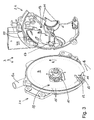
- FIG. 2a and FIG. 3 is the sheherz 3 with its two halves 3.1 and 3.2 (see FIG. 3 ), wherein the working space 8 enclosed by the two halves 3.1 and 3.2 is subdivided by a seed disc 9 into a pressure chamber 10 and a seed chamber 11.
- the pressure chamber 10 is divided by a, preferably conventional, sealing ring 12 into a negative pressure region 13 and a normal pressure region 14. It is essential that in the negative pressure region 13 serving for receiving and delivering seed sewer holes 15 of the seed disc 9 a pressure difference is applied, which is dissolved in the normal pressure region 14, whereby the transition of the sumps 15 from the negative pressure region 13 in the normal pressure region 14, the seed 16 by rotational movement the sowing disc 9 is dropped in a running direction R of the seed disc 9.
- the seed chamber 11 is according to FIG. 3 divided into a storage section 17 and a transport and discharge section 18, wherein the subdivision is effected by a partition wall 19.
- the negative pressure region 13 is acted upon by a pump, not shown, or a negative pressure blower via the port 13 a with negative pressure.
- the seed 16 is stored from the channel 4k and constantly refilled, while on the rotating sheefficiency 9 constantly received individual grains of the seed 16 and from the storage section 17 via the transport and discharge section 18 in by the distances between the Söchöchern 15th predetermined intervals to the coulter 5 (see FIG. 1a, 1b ).
- a, in particular adjustable, scraper 20 for stripping excess grains is provided so that only one grain per sowing hole 15 is present.
- the sumps 15 are arranged on a circular path of the seed disc 9 at defined intervals, with several circular paths can be provided with shelöchern 15.
- the decisive for the present invention component is in FIG. 2b
- the half of the preseherzes 3 3.1 is penetrated by a drive shaft 22 which is driven by a motor, not shown, or a drive wheel via gearbox.
- the flange 25 is rotationally fixedly connected to the drive shaft 22 by projections 26 of the drive shaft 22 and corresponding recesses 27 of the flange 25th
Landscapes
- Life Sciences & Earth Sciences (AREA)
- Soil Sciences (AREA)
- Environmental Sciences (AREA)
- Sowing (AREA)
- Pretreatment Of Seeds And Plants (AREA)
Abstract
- einer durch eine rotierbare Säscheibe (9) von einer Druckkammer (10) getrennten Saatgutkammer (11),
- die Säscheibe (9) weist Sälöcher (15) in definierter Anordnung zur definierten Aufnahme und Abgabe von Saatgut (16) mittels durch die Druckkammer (10) definierte Druckabschnitte (13,14) auf,
- die Saatgutkammer (11) ist in einen Bevorratungsabschnitt (17) und einen Transport- und Abgabeabschnitt (18) geteilt,
- der Bevorratungsabschnitt (17) ist durch eine Trennwand (19) zumindest teilweise gegenüber dem Transport- und Abgabeabschnitt (18) gedichtet, wobei die Säscheibe (9) durch eine stufenlose Stelleinrichtung gegenüber der Trennwand (19) einstellbar ist. Weiterhin betrifft die Erfindung eine Einzelkornsämaschine mit einer Vielzahl von Säaggregaten mit jeweils mindestens einem vorgenannten Säherz (3).
Description
- Die Erfindung betrifft ein Säherz nach Anspruch 1 und eine Einzelkornsämaschine nach Anspruch 8.
- Solche Einzelkornsämaschinen weisen meist eine Mehrzahl von Säreihen mit einer Vielzahl von Säherzen auf. Bekannte Säherzen für pneumatische Einzelkornsäaggregate bestehen in der Regel aus zwei Hälften, nämlich einem hinteren Teil, in welchem die Lagerung der Säscheibe und der Unterdruckbereich untergebracht sind und einem vorderen Teil, in welchen der untere Ausgang des Saatgutbehälters mündet und der selbst einen Saatgutspeicher aufweist.
- Die Säscheibe bildet dabei eine Trennwand zum Unterdruckbereich sowie eine Trennwand des Saatgutspeichers.
- Besondere Bedeutung kommt dabei der Abdichtung des Saatgutspeichers zu, da auf Grund der rotierenden Säscheibe und der unterschiedlichen Druckverhältnisse auf den beiden Seiten der Säscheibe Saatgut, insbesondere Feinsaatgut wie Gemüsesamen, aus dem Saatgutspeicher unplanmäßig entweichen kann, wodurch sogar die Rotation der Säscheibe behindert werden kann.
- Um eine möglichst dichte Abtrennung des Saatgutspeichers, insbesondere im Bereich der Schnittstelle zwischen der Wand des Saatgutspeichers und der an dieser Wand anliegenden rotierenden Säscheibe, sicherzustellen, ist eine besonders sorgfältige Anpassung der Säscheibe erforderlich. Im Stand der Technik wird die Wand in der Regel manuell eingeschliffen, wodurch die Produktion der Säherzen erheblich verteuert wird.
- Weiterhin ergibt sich daraus der Nachteil, dass die aufeinander angepassten Hälften des Säherzes nicht gegenseitig austauschbar sind, obwohl insbesondere auf Grund der Vielzahl von Säherzen pro Sämaschine ein einfacheres Austauschen, beispielsweise beim Säscheibenwechsel, wünschenswert wäre.
- Aufgabe der vorliegenden Erfindung ist es daher, ein einfach zu handhabendes Säherz vorzusehen, das günstiger herzustellen ist und dessen Bauteile möglichst einfach und flexibel austauschbar sind.
- Diese Aufgabe wird mit einem Säherz mit den Merkmalen des Anspruchs 1 sowie einer Einzelkornsämaschine mit den Merkmalen des Anspruchs 8 gelöst. Vorteilhafte Weiterbildungen der Erfindung sind in den Unteransprüchen angegeben. In den Rahmen der Erfindung fallen sämtliche Kombinationen aus zumindest zwei in der Beschreibung, den Ansprüchen und/oder den Figuren offenbarten Merkmalen.
- Grundidee der vorliegenden Erfindung ist es, die Säscheibe des Säherzes durch eine in axialer Richtung wirkende Stelleinrichtung gegenüber der Trennwand des Saatgutspeichers in axialer Richtung zumindest teilweise stufenlos einstellbar auszugestalten. Dies wird insbesondere durch Vorsehen eines durch ein Stellglied beaufschlagten Flansches auf der Achse/Antriebswelle des Säherzes erreicht, der durch ein Spannelement gegenüber dem Stellglied vorgespannt wird. Stellglied, Flansch und Spannelement sind Bestandteile der Stelleinrichtung.
- Mit anderen Worten: Die Säscheibe ist auf einem axial auf der Achse/Antriebswelle der Säscheibe montierten Flansch, der mit dem oben genannten Flansch identisch ist oder durch diesen gebildet ist, durch ein Stellglied, insbesondere eine Mutter, axial verstellbar beziehungsweise einstellbar, vorzugsweise in einem kleinen, aber exakten Verstellbereich von bevorzugt weniger als 1 mm, noch bevorzugter weniger als 0,5 mm. Der Flansch ist von seiner Rückseite durch das Spannelement vorgespannt und nimmt auf seiner Vorderseite die Säscheibe rotationsfest auf.
- Durch die vorbeschriebene Maßnahme ist es erstmals möglich, die Säscheibe ohne vorheriges Einschleifen der Hälften des Säherzes einzubauen/auszuwechseln. Beim Bruch oder Austausch von Hälften des Säherzes oder anderen Bestandteilen ist es nicht mehr erforderlich, das ganze, teure Säherz auszutauschen.
- Weiterhin ermöglicht diese Konstruktion eine Einstellung des axialen Abstands zwischen Trennwand und Säscheibe ohne Ausbau der Säscheibe.
- Eine durch die Trennwand gebildete Trennwandebene ist parallel zu einer durch die Säscheibe gebildeten Säscheibenebene, wobei die Säscheibenebene durch die Stelleinrichtung gegenüber der Trennwandebene parallelverschieblich ausgebildet ist.
- Nach der Montage der Säscheibe kann daher der Spalt zwischen Trennwand und rotierbarer Säscheibe durch das Stellglied im Rahmen der Fertigungsgenauigkeiten mit Vorteil auf ein Minimum, vorzugsweise auf Null reduziert werden, ohne dass beim Betrieb des Säherzes durch Reibung zwischen Trennwand und Säscheibe ein wesentlicher Abrieb entsteht. Die Anpreßkraft der Säscheibe auf die Trennwand ist in vorteilhafter Weise im Rahmen der Fertigungsgenauigkeiten ebenfalls auf ein Minimum, insbesondere auf Null, zu reduzieren.
- Durch die erfindungsgemäße Ausgestaltung ergibt sich der Vorteil, dass das Saatgut nicht zwischen Trennwand und Säscheibe gezogen wird und das teure Saatgut unkontrolliert auf den Ackerboden gelangt oder gar zerstört wird.
- Unter dem Begriff Saatgut im Rahmen der vorliegenden Offenbarung sind beispielsweise Dünger, Samenkörner, ob pilliert oder nackt, subsumierbar.
- Durch die, insbesondere mit geringem Federweg, federbeaufschlagte Lagerung der rotierenden Säscheibe wird die Säscheibe genau gegenüber der Trennwand positioniert, so dass der Bevorratungsabschnitt mit dem Saatgutspeicher und der Transport-/Abgabeabschnitt optimal abgetrennt, insbesondere abgedichtet, sind und selbst Kleinstsaatgut über eine lange Laufzeit des Säherzes ohne Verlust im Bevorratungsabschnitt verbleibt.
- In einer vorteilhaften Ausführungsform der Erfindung weist die Stelleinrichtung ein Spannelement, insbesondere eine Feder, vorzugsweise eine Flachfeder, noch bevorzugter eine Tellerfeder, zur Beaufschlagung der Säscheibe gegen ein Stellglied der Stelleinrichtung auf. Durch die flache Form einer Tellerfeder sowie die definierte und hohe Kraftübertragung einer Tellerfeder wird eine optimale Umsetzung der Anforderungen an das Spannelement ermöglicht, nämlich eine Platz sparende Unterbringung unterhalb der Säscheibe mit einem geringen Federhub beziehungsweise Federweg.
- Mit Vorteil ist das Spannelement gemeinsam mit der Säscheibe rotierbar, damit ein gegenseitiges Abtragen möglichst vermieden wird.
- Weiterhin ist das Spannelement mit Vorteil auf einer Antriebswelle zur Rotation der Säscheibe angeordnet, da hierdurch eine optimale Kraftverteilung wegen der zentrischen Anordnung des Spannelements erfolgt. Besonders vorteilhaft ist dabei die Kombination mit der oben beschriebenen Tellerfeder.
- Soweit die durch das Spannelement erzeugte Vorspannkraft und die Rotationskraft der Antriebswelle über einen, insbesondere mit der Antriebswelle rotationsfest fixierten, Flansch auf die Säscheibe übertragen wird, ist mit Vorteil eine optimale Kraftübertragung sowohl der Rotationskraft als auch der Vorspannkraft zwischen Spannelement, Antriebswelle und Säscheibe sowie dem Stellglied möglich.
- Es ist auch denkbar, das Spannelement und den Flansch einteilig aus einem elastischen Werkstoff zu fertigen, der entsprechende Federeigenschaften, beispielsweise entsprechend der Tellerfeder, hat. Dabei kann der Flansch aus Kunststoff, beispielsweise PA6, mit einem im Zentrum des Flansches eingebrachten elastischen Werkstoff, beispielsweise PU, gebildet sein.
- Weitere Vorteile, Merkmale und Einzelheiten der Erfindung ergeben sich aus der nachfolgenden Beschreibung bevorzugter Ausführungsbeispiele sowie an Hand der Zeichnungen. Diese zeigen in:
- Fig. 1a und 1 b:
- perspektivische Ansichten eines Einzelkornsäaggregats einer erfindungsgemäßen Einzelkornsämaschine von schräg hinten (
Figur 1a ) und von schräg vorne (Figur 1b ), - Figur 2a:
- eine perspektivische Ansicht eines teilweise aufgeschnittenen erfindungsgemäßen Säherzes,
- Figur 2b:
- eine Detailansicht aus
Figur 2a betreffend die Antriebswelle beziehungsweise Achse des erfindungsgemäßen Säherzes und - Figur 3:
- eine perspektivische, aufgeklappte Ansicht des erfindungsgemäßen Säherzes, teilweise aufgeschnitten.
- In den Figuren sind gleiche Bauteile und Bauteile mit der gleichen Funktion mit den gleichen Bezugszeichen gekennzeichnet.
- In
Figuren 1a und1b ist ein Säaggregat 1 einer erfindungsgemäßen Einzelkornsämaschine dargestellt, das über einen Arm 2 am Rahmen der Einzelkornsämaschine befestigt ist. Dementsprechend ist die Fahrtrichtung beim Betrieb der Einzelkornsämaschine in der durch Pfeil F angegebenen Richtung. - An dem Arm 2, der eine Schwenkbewegung, vorzugsweise als Vertikalbewegung durch Ausbildung des Arms 2 als Parallelogrammarm, zulässt, sind ein Säherz 3, ein oberhalb des Säherzes 3 angeordneter Tank 4, ein unterhalb des Säherzes 3 angeordnetes Säschar 5 sowie zwei in Fahrtrichtung F vor und hinter dem Säherzen 3 angeordnete, gegenüber dem Säherz 3 schwenkbare Laufräder 6 angebracht.
- Der Tank 4 ist über einen Deckel 4d verschließbar und mit Saatgut 16 befüllbar, das wiederum über einen Kanal 4k seitlich in das Säherz 3 geführt wird.
- Das Saatgut 16 wird im Säherz 3 vereinzelt und über das Säschar 5 in eine durch eine Scharspitze 7 des Säschars 5 geöffnete Furche im Ackerboden abgelegt.
- In
Figur 2a undFigur 3 ist das Säherz 3 mit seinen beiden Hälften 3.1 und 3.2 (sieheFigur 3 ) dargestellt, wobei der durch die beiden Hälften 3.1 und 3.2 umschlossene Arbeitsraum 8 durch eine Säscheibe 9 in eine Druckkammer 10 und eine Saatgutkammer 11 unterteilt wird. - Die Druckkammer 10 ist durch einen, vorzugsweise herkömmlichen, Dichtring 12 in einen Unterdruckbereich 13 und einen Normaldruckbereich 14 aufgeteilt. Wesentlich ist dabei, dass im Unterdruckbereich 13 an zur Aufnahme und Abgabe von Saatgut dienenden Sälöchern 15 der Säscheibe 9 eine Druckdifferenz anliegt, die im Normaldruckbereich 14 aufgelöst wird, wodurch beim Übergang der Sälöcher 15 vom Unterdruckbereich 13 in den Normaldruckbereich 14 das Saatgut 16 durch Rotationsbewegung der Säscheibe 9 in einer Laufrichtung R der Säscheibe 9 abgeworfen wird.
- Die Saatgutkammer 11 ist gemäß
Figur 3 in einen Bevorratungsabschnitt 17 und einen Transport- und Abgabeabschnitt 18 unterteilt, wobei die Unterteilung durch eine Trennwand 19 erfolgt. - Der Unterdruckbereich 13 wird von einer nicht dargestellten Pumpe oder einem Unterdruckgebläse über den Anschluss 13a mit Unterdruck beaufschlagt.
- Im Bevorratungsabschnitt 17 wird das Saatgut 16 aus dem Kanal 4k gespeichert und konstant nachgefüllt, während über die sich drehende Säscheibe 9 konstant einzelne Körner des Saatguts 16 aufgenommen und aus dem Bevorratungsabschnitt 17 über den Transport- und Abgabeabschnitt 18 in durch die Abstände zwischen den Sälöchern 15 vorgegebenen Intervallen an das Säschar 5 (siehe
Figur 1a, 1b ) abgegeben werden. - Sollten an einem Säloch 15 mehrere Körner des Saatguts 16 anhaften, ist ein, insbesondere einstellbarer, Abstreifer 20 zum Abstreifen überschüssiger Körner vorgesehen, so dass jeweils nur ein Korn pro Säloch 15 anliegt.
- Die Sälöcher 15 sind auf einer Kreisbahn der Säscheibe 9 in definierten Abständen angeordnet, wobei auch mehrere Kreisbahnen mit Sälöchern 15 vorgesehen sein können.
- Das für die vorliegende Erfindung entscheidende Bauteil ist in
Figur 2b vergrößert dargestellt, nämlich die Lagerung 21 der Säscheibe 9. Die Hälfte 3.1 des Säherzes 3 ist von einer Antriebswelle 22 durchsetzt, die von einem nicht dargestellten Motor oder einem Antriebsrad via Getriebe antreibbar ist. - Auf einem zur Säscheibe 9 gerichteten Absatz 23 ist zwischen dem Absatz 23, an diesem anliegend und einem Flansch 25, ein Spannelement 24, nämlich hier eine Tellerfeder, ringförmig um die Antriebswelle 22 angeordnet die sich auf Ihrer von dem Absatz 23 abgewandten Seite gegen einen Flansch 25 abstützt.
- Der Flansch 25 ist rotationskraftschlüssig mit der Antriebswelle 22 verbunden und zwar durch Vorsprünge 26 der Antriebswelle 22 und korrespondierende Ausnehmungen 27 des Flansches 25.
- Durch eine gegen Lösen gesicherte Mutter 28 ist der Abstand A zwischen Absatz 23 und Flansch 25 und damit der Abstand zwischen Absatz 23 und Säscheibe 9 exakt einstellbar, so dass ein Einschleifen der Trennwand 19 auf die konkreten Abmessungen des Säherzes 3 im Bereich der Trennwand 19 nicht mehr oder nur in verhältnismäßig geringem Umfang notwendig ist. Die auf die Trennwand 19 wirkende Druckkraft bleibt über eine sehr lange Laufzeit des Säherzes 3 selbst bei Abrieb der Trennwand 19 und/oder der Säscheibe 9 annähernd konstant.
-
- A
- Abstand
- F
- Fahrtrichtung
- R
- Laufrichtung Säscheibe
- 1
- Säaggregat
- 2
- Arm
- 3
- Säherz
- 3.1
- Hälfte
- 3.2
- Hälfte
- 4
- Tank
- 4d
- Deckel
- 4k
- Kanal
- 5
- Säschar
- 6
- Laufräder
- 7
- Scharspitze
- 8
- Arbeitsraum
- 9
- Säscheibe
- 10
- Druckkammer
- 11
- Saatgutkammer
- 12
- Dichtring
- 13
- Unterdruckbereich
- 13a
- Anschluss
- 14
- Normaldruckbereich
- 15
- Sälöcher
- 16
- Saatgut
- 17
- Bevorratungsabschnitt
- 18
- Transport- und Abgabeabschnitt
- 19
- Trennwand
- 20
- Abstreifer
- 21
- Lagerung
- 22
- Antriebswelle
- 23
- Absatz
- 24
- Spannelement
- 25
- Flansch
- 26
- Vorsprung
- 27
- Ausnehmungen
- 28
- Stellglied, insbesondere Mutter
Claims (8)
- Säherz (3) für eine Einzelkornsämaschine mit folgenden Merkmalen:- eine durch eine rotierbare Säscheibe (9) von einer Druckkammer (10) getrennte Saatgutkammer (11),- die Säscheibe (9) weist Sälöcher (15) in definierter Anordnung zur definierten Aufnahme und Abgabe von Saatgut (16) mittels durch die Druckkammer (10) definierte Druckabschnitte (13, 14) auf,- die Saatgutkammer (11) ist in einen Bevorratungsabschnitt (17) und einen Transport- und Abgabeabschnitt (18) geteilt,- der Bevorratungsabschnitt ist durch eine Trennwand (19) zumindest teilweise gegenüber dem Transport- und Abgabeabschnitt (18) getrennt,dadurch gekennzeichnet, dass
die Säscheibe (9) durch eine zumindest teilweise stufenlose Stelleinrichtung gegenüber der Trennwand (19) einstellbar ist. - Säherz (3) nach Anspruch 1, dadurch gekennzeichnet,
dass die Stelleinrichtung ein Spannelement (24), insbesondere eine Feder, vorzugsweise eine Flachfeder, noch bevorzugter eine Tellerfeder, zur Beaufschlagung der Säscheibe (9) gegen ein Stellglied (28) der Stelleinrichtung aufweist. - Säherz (3) nach Anspruch 2, dadurch gekennzeichnet,
dass das Spannelement (24) mit der Säscheibe (9) rotierbar angeordnet ist. - Säherz (3) nach Anspruch 2 oder 3, dadurch gekennzeichnet,
dass das Spannelement (24) auf einer Antriebswelle (22) zur Rotation der Säscheibe (9) angeordnet ist. - Säherz (3) nach einem der Ansprüche 2 bis 4, dadurch gekennzeichnet,
dass die Stelleinrichtung einen Flansch (25) zwischen Spannelement (24) und der Säscheibe (9) zur Übertragung der Rotationskraft von einer Antriebswelle (22) des Säherzes (3) auf die Säscheibe (9) aufweist. - Säherz (3) nach einem der Ansprüche 2 bis 5, dadurch gekennzeichnet,
dass der Federweg der Feder kleiner als 1 mm, insbesondere kleiner als 0,5 mm, ist. - Säherz (3) nach Anspruch 1, dadurch gekennzeichnet,
dass eine durch die Trennwand gebildete Trennwandebene parallel zu einer durch die Säscheibe gebildeten Säscheibenebene angeordnet ist, wobei die Säscheibenebene durch die Stelleinrichtung gegenüber der Trennwandebene parallelverschieblich ausgebildet ist. - Einzelkornsämaschine mit mindestens einem Säherz (3) nach einem der vorhergehenden Ansprüche.
Priority Applications (1)
| Application Number | Priority Date | Filing Date | Title |
|---|---|---|---|
| PL09013943T PL2183952T3 (pl) | 2008-11-08 | 2009-11-06 | Aparat wysiewający i siewnik punktowy |
Applications Claiming Priority (1)
| Application Number | Priority Date | Filing Date | Title |
|---|---|---|---|
| DE102008056534A DE102008056534A1 (de) | 2008-11-08 | 2008-11-08 | Säherz und Einzelkornsämaschine |
Publications (2)
| Publication Number | Publication Date |
|---|---|
| EP2183952A1 true EP2183952A1 (de) | 2010-05-12 |
| EP2183952B1 EP2183952B1 (de) | 2011-04-27 |
Family
ID=41630235
Family Applications (1)
| Application Number | Title | Priority Date | Filing Date |
|---|---|---|---|
| EP09013943A Active EP2183952B1 (de) | 2008-11-08 | 2009-11-06 | Säherz und Einzelkornsämaschine |
Country Status (5)
| Country | Link |
|---|---|
| EP (1) | EP2183952B1 (de) |
| AT (1) | ATE506845T1 (de) |
| DE (2) | DE102008056534A1 (de) |
| ES (1) | ES2363489T3 (de) |
| PL (1) | PL2183952T3 (de) |
Cited By (2)
| Publication number | Priority date | Publication date | Assignee | Title |
|---|---|---|---|---|
| CN102612904A (zh) * | 2012-03-28 | 2012-08-01 | 华南农业大学 | 一种播量可调的组合型孔排种器 |
| EP4427565A1 (de) * | 2023-03-07 | 2024-09-11 | Amazonen-Werke H. Dreyer SE & Co. KG | Dosiereinrichtung zum dosieren von ausbringmaterial und verfahren zum einstellen einer dosiereinrichtung |
Families Citing this family (5)
| Publication number | Priority date | Publication date | Assignee | Title |
|---|---|---|---|---|
| DE102011002223B3 (de) | 2011-04-21 | 2012-10-31 | Franz Kleine Vertriebs & Engineering Gmbh | Einzelkornausbringeinrichtung |
| DE102013102123B4 (de) * | 2013-03-04 | 2016-03-10 | Kverneland As | Säherz und Verfahren zur Beschichtung des Säherzes |
| PL3320764T3 (pl) | 2016-11-10 | 2020-06-29 | Kverneland As | Zespół wysiewający do siewnika |
| DE202017102974U1 (de) | 2017-05-17 | 2017-06-22 | Kverneland A/S | Säherzgehäuse |
| PL443783A1 (pl) * | 2023-02-14 | 2023-08-14 | Akpil Spółka Z Ograniczoną Odpowiedzialnością | Dozownik nasion roślin uprawnych |
Citations (3)
| Publication number | Priority date | Publication date | Assignee | Title |
|---|---|---|---|---|
| EP0193833A1 (de) | 1985-02-25 | 1986-09-10 | Deere & Company | Sävorrichtung |
| DE3831042A1 (de) * | 1987-09-15 | 1989-03-30 | Agrozet Koncern Zemedelskeho | Vorrichtung zur axialen verstellung eines drehbaren maschinenteils |
| US5170909A (en) * | 1983-10-31 | 1992-12-15 | Deere & Company | Vacuum seed meter |
Family Cites Families (1)
| Publication number | Priority date | Publication date | Assignee | Title |
|---|---|---|---|---|
| AT321623B (de) * | 1973-08-25 | 1975-04-10 | Prillinger Landmaschf Hans | Einzelkornsaemaschine |
-
2008
- 2008-11-08 DE DE102008056534A patent/DE102008056534A1/de not_active Withdrawn
-
2009
- 2009-11-06 AT AT09013943T patent/ATE506845T1/de active
- 2009-11-06 EP EP09013943A patent/EP2183952B1/de active Active
- 2009-11-06 PL PL09013943T patent/PL2183952T3/pl unknown
- 2009-11-06 ES ES09013943T patent/ES2363489T3/es active Active
- 2009-11-06 DE DE502009000584T patent/DE502009000584D1/de active Active
Patent Citations (3)
| Publication number | Priority date | Publication date | Assignee | Title |
|---|---|---|---|---|
| US5170909A (en) * | 1983-10-31 | 1992-12-15 | Deere & Company | Vacuum seed meter |
| EP0193833A1 (de) | 1985-02-25 | 1986-09-10 | Deere & Company | Sävorrichtung |
| DE3831042A1 (de) * | 1987-09-15 | 1989-03-30 | Agrozet Koncern Zemedelskeho | Vorrichtung zur axialen verstellung eines drehbaren maschinenteils |
Cited By (2)
| Publication number | Priority date | Publication date | Assignee | Title |
|---|---|---|---|---|
| CN102612904A (zh) * | 2012-03-28 | 2012-08-01 | 华南农业大学 | 一种播量可调的组合型孔排种器 |
| EP4427565A1 (de) * | 2023-03-07 | 2024-09-11 | Amazonen-Werke H. Dreyer SE & Co. KG | Dosiereinrichtung zum dosieren von ausbringmaterial und verfahren zum einstellen einer dosiereinrichtung |
Also Published As
| Publication number | Publication date |
|---|---|
| ATE506845T1 (de) | 2011-05-15 |
| EP2183952B1 (de) | 2011-04-27 |
| DE102008056534A1 (de) | 2010-05-27 |
| ES2363489T3 (es) | 2011-08-05 |
| DE502009000584D1 (de) | 2011-06-09 |
| PL2183952T3 (pl) | 2011-08-31 |
Similar Documents
| Publication | Publication Date | Title |
|---|---|---|
| EP2183952B1 (de) | Säherz und Einzelkornsämaschine | |
| DE69414319T2 (de) | Einzelkornsämaschine | |
| DE102013100118B3 (de) | Abstreifeinrichtung, Säherz und Einzelkornsämaschine | |
| EP0237766B1 (de) | Pneumatische Einzelkornsämaschine | |
| EP0169333B1 (de) | Vorrichtung zum Vereinzeln und Verteilen von körnigem Gut | |
| EP2341765B1 (de) | Säherz für eine Einzelkornsämaschine | |
| EP0155688A2 (de) | Sämaschine | |
| EP2807914B2 (de) | Säherzsteuerungseinrichtung, Säherz und Einzelkornsämaschine | |
| EP0193833A1 (de) | Sävorrichtung | |
| DE102015121039A1 (de) | Verteilvorrichtung, Düngevorrichtung und Verfahren zum Verteilen von flüssigen Substanzen | |
| EP2989877B1 (de) | Dosieraggregat für körniges gut | |
| DE102019106758A1 (de) | Schneidvorrichtung; Separierer; Verfahren zum Separieren von Lebensmittelbestandteilen mittels eines Separierers | |
| DE3405361C1 (de) | Pnaumatische Einzelkornsaemaschine | |
| DE102013100113B4 (de) | Abstreifer, Abstreifeinrichtung, Säherz | |
| DE3541991C2 (de) | ||
| EP2974583B1 (de) | Säherz und Einzelkornsämaschine | |
| DE102011002223B3 (de) | Einzelkornausbringeinrichtung | |
| DE202020107208U1 (de) | Verteilervorrichtung zum Verteilen von feststoffhaltigen Flüssigkeiten | |
| EP0143298A1 (de) | Sävorrichtung | |
| DE2705479C2 (de) | Abstreifer einer Einzelkorn-Sävorrichtung | |
| DE19805489C1 (de) | Vorrichtung mit hoher Regelbandbreite zum präzisen Verteilen von Streugut | |
| EP0331931B1 (de) | Einzelkornsämaschine | |
| DE1962150B2 (de) | Pneumatische Einzelkornsävorrichtung | |
| EP0356771A2 (de) | Pneumatische Einzelkornsämaschine | |
| DE3120568C2 (de) | Einzelkornsägerät |
Legal Events
| Date | Code | Title | Description |
|---|---|---|---|
| PUAI | Public reference made under article 153(3) epc to a published international application that has entered the european phase |
Free format text: ORIGINAL CODE: 0009012 |
|
| AK | Designated contracting states |
Kind code of ref document: A1 Designated state(s): AT BE BG CH CY CZ DE DK EE ES FI FR GB GR HR HU IE IS IT LI LT LU LV MC MK MT NL NO PL PT RO SE SI SK SM TR |
|
| AX | Request for extension of the european patent |
Extension state: AL BA RS |
|
| 17P | Request for examination filed |
Effective date: 20100619 |
|
| 17Q | First examination report despatched |
Effective date: 20100716 |
|
| GRAP | Despatch of communication of intention to grant a patent |
Free format text: ORIGINAL CODE: EPIDOSNIGR1 |
|
| RIC1 | Information provided on ipc code assigned before grant |
Ipc: A01C 7/04 20060101AFI20101130BHEP |
|
| GRAS | Grant fee paid |
Free format text: ORIGINAL CODE: EPIDOSNIGR3 |
|
| GRAA | (expected) grant |
Free format text: ORIGINAL CODE: 0009210 |
|
| AK | Designated contracting states |
Kind code of ref document: B1 Designated state(s): AT BE BG CH CY CZ DE DK EE ES FI FR GB GR HR HU IE IS IT LI LT LU LV MC MK MT NL NO PL PT RO SE SI SK SM TR |
|
| REG | Reference to a national code |
Ref country code: GB Ref legal event code: FG4D Free format text: NOT ENGLISH |
|
| REG | Reference to a national code |
Ref country code: CH Ref legal event code: EP |
|
| REG | Reference to a national code |
Ref country code: IE Ref legal event code: FG4D Free format text: LANGUAGE OF EP DOCUMENT: GERMAN |
|
| REF | Corresponds to: |
Ref document number: 502009000584 Country of ref document: DE Date of ref document: 20110609 Kind code of ref document: P |
|
| REG | Reference to a national code |
Ref country code: DE Ref legal event code: R096 Ref document number: 502009000584 Country of ref document: DE Effective date: 20110609 |
|
| REG | Reference to a national code |
Ref country code: NL Ref legal event code: T3 |
|
| REG | Reference to a national code |
Ref country code: ES Ref legal event code: FG2A Ref document number: 2363489 Country of ref document: ES Kind code of ref document: T3 Effective date: 20110805 |
|
| REG | Reference to a national code |
Ref country code: PL Ref legal event code: T3 |
|
| LTIE | Lt: invalidation of european patent or patent extension |
Effective date: 20110427 |
|
| PG25 | Lapsed in a contracting state [announced via postgrant information from national office to epo] |
Ref country code: PT Free format text: LAPSE BECAUSE OF FAILURE TO SUBMIT A TRANSLATION OF THE DESCRIPTION OR TO PAY THE FEE WITHIN THE PRESCRIBED TIME-LIMIT Effective date: 20110829 Ref country code: HR Free format text: LAPSE BECAUSE OF FAILURE TO SUBMIT A TRANSLATION OF THE DESCRIPTION OR TO PAY THE FEE WITHIN THE PRESCRIBED TIME-LIMIT Effective date: 20110427 Ref country code: LT Free format text: LAPSE BECAUSE OF FAILURE TO SUBMIT A TRANSLATION OF THE DESCRIPTION OR TO PAY THE FEE WITHIN THE PRESCRIBED TIME-LIMIT Effective date: 20110427 Ref country code: NO Free format text: LAPSE BECAUSE OF FAILURE TO SUBMIT A TRANSLATION OF THE DESCRIPTION OR TO PAY THE FEE WITHIN THE PRESCRIBED TIME-LIMIT Effective date: 20110727 Ref country code: SE Free format text: LAPSE BECAUSE OF FAILURE TO SUBMIT A TRANSLATION OF THE DESCRIPTION OR TO PAY THE FEE WITHIN THE PRESCRIBED TIME-LIMIT Effective date: 20110427 |
|
| REG | Reference to a national code |
Ref country code: IE Ref legal event code: FD4D |
|
| PG25 | Lapsed in a contracting state [announced via postgrant information from national office to epo] |
Ref country code: IS Free format text: LAPSE BECAUSE OF FAILURE TO SUBMIT A TRANSLATION OF THE DESCRIPTION OR TO PAY THE FEE WITHIN THE PRESCRIBED TIME-LIMIT Effective date: 20110827 Ref country code: SI Free format text: LAPSE BECAUSE OF FAILURE TO SUBMIT A TRANSLATION OF THE DESCRIPTION OR TO PAY THE FEE WITHIN THE PRESCRIBED TIME-LIMIT Effective date: 20110427 Ref country code: FI Free format text: LAPSE BECAUSE OF FAILURE TO SUBMIT A TRANSLATION OF THE DESCRIPTION OR TO PAY THE FEE WITHIN THE PRESCRIBED TIME-LIMIT Effective date: 20110427 Ref country code: GR Free format text: LAPSE BECAUSE OF FAILURE TO SUBMIT A TRANSLATION OF THE DESCRIPTION OR TO PAY THE FEE WITHIN THE PRESCRIBED TIME-LIMIT Effective date: 20110728 Ref country code: LV Free format text: LAPSE BECAUSE OF FAILURE TO SUBMIT A TRANSLATION OF THE DESCRIPTION OR TO PAY THE FEE WITHIN THE PRESCRIBED TIME-LIMIT Effective date: 20110427 Ref country code: CY Free format text: LAPSE BECAUSE OF FAILURE TO SUBMIT A TRANSLATION OF THE DESCRIPTION OR TO PAY THE FEE WITHIN THE PRESCRIBED TIME-LIMIT Effective date: 20110427 |
|
| PG25 | Lapsed in a contracting state [announced via postgrant information from national office to epo] |
Ref country code: EE Free format text: LAPSE BECAUSE OF FAILURE TO SUBMIT A TRANSLATION OF THE DESCRIPTION OR TO PAY THE FEE WITHIN THE PRESCRIBED TIME-LIMIT Effective date: 20110427 Ref country code: IE Free format text: LAPSE BECAUSE OF FAILURE TO SUBMIT A TRANSLATION OF THE DESCRIPTION OR TO PAY THE FEE WITHIN THE PRESCRIBED TIME-LIMIT Effective date: 20110427 Ref country code: CZ Free format text: LAPSE BECAUSE OF FAILURE TO SUBMIT A TRANSLATION OF THE DESCRIPTION OR TO PAY THE FEE WITHIN THE PRESCRIBED TIME-LIMIT Effective date: 20110427 |
|
| PG25 | Lapsed in a contracting state [announced via postgrant information from national office to epo] |
Ref country code: DK Free format text: LAPSE BECAUSE OF FAILURE TO SUBMIT A TRANSLATION OF THE DESCRIPTION OR TO PAY THE FEE WITHIN THE PRESCRIBED TIME-LIMIT Effective date: 20110427 Ref country code: RO Free format text: LAPSE BECAUSE OF FAILURE TO SUBMIT A TRANSLATION OF THE DESCRIPTION OR TO PAY THE FEE WITHIN THE PRESCRIBED TIME-LIMIT Effective date: 20110427 Ref country code: SK Free format text: LAPSE BECAUSE OF FAILURE TO SUBMIT A TRANSLATION OF THE DESCRIPTION OR TO PAY THE FEE WITHIN THE PRESCRIBED TIME-LIMIT Effective date: 20110427 |
|
| PLBE | No opposition filed within time limit |
Free format text: ORIGINAL CODE: 0009261 |
|
| STAA | Information on the status of an ep patent application or granted ep patent |
Free format text: STATUS: NO OPPOSITION FILED WITHIN TIME LIMIT |
|
| 26N | No opposition filed |
Effective date: 20120130 |
|
| REG | Reference to a national code |
Ref country code: DE Ref legal event code: R097 Ref document number: 502009000584 Country of ref document: DE Effective date: 20120130 |
|
| PG25 | Lapsed in a contracting state [announced via postgrant information from national office to epo] |
Ref country code: MC Free format text: LAPSE BECAUSE OF NON-PAYMENT OF DUE FEES Effective date: 20111130 |
|
| PG25 | Lapsed in a contracting state [announced via postgrant information from national office to epo] |
Ref country code: MK Free format text: LAPSE BECAUSE OF FAILURE TO SUBMIT A TRANSLATION OF THE DESCRIPTION OR TO PAY THE FEE WITHIN THE PRESCRIBED TIME-LIMIT Effective date: 20110427 Ref country code: MT Free format text: LAPSE BECAUSE OF FAILURE TO SUBMIT A TRANSLATION OF THE DESCRIPTION OR TO PAY THE FEE WITHIN THE PRESCRIBED TIME-LIMIT Effective date: 20110427 |
|
| PG25 | Lapsed in a contracting state [announced via postgrant information from national office to epo] |
Ref country code: SM Free format text: LAPSE BECAUSE OF FAILURE TO SUBMIT A TRANSLATION OF THE DESCRIPTION OR TO PAY THE FEE WITHIN THE PRESCRIBED TIME-LIMIT Effective date: 20110427 |
|
| PG25 | Lapsed in a contracting state [announced via postgrant information from national office to epo] |
Ref country code: LU Free format text: LAPSE BECAUSE OF NON-PAYMENT OF DUE FEES Effective date: 20111106 |
|
| PG25 | Lapsed in a contracting state [announced via postgrant information from national office to epo] |
Ref country code: BG Free format text: LAPSE BECAUSE OF FAILURE TO SUBMIT A TRANSLATION OF THE DESCRIPTION OR TO PAY THE FEE WITHIN THE PRESCRIBED TIME-LIMIT Effective date: 20110727 |
|
| PG25 | Lapsed in a contracting state [announced via postgrant information from national office to epo] |
Ref country code: TR Free format text: LAPSE BECAUSE OF FAILURE TO SUBMIT A TRANSLATION OF THE DESCRIPTION OR TO PAY THE FEE WITHIN THE PRESCRIBED TIME-LIMIT Effective date: 20110427 |
|
| PG25 | Lapsed in a contracting state [announced via postgrant information from national office to epo] |
Ref country code: HU Free format text: LAPSE BECAUSE OF FAILURE TO SUBMIT A TRANSLATION OF THE DESCRIPTION OR TO PAY THE FEE WITHIN THE PRESCRIBED TIME-LIMIT Effective date: 20110427 |
|
| REG | Reference to a national code |
Ref country code: CH Ref legal event code: PL |
|
| PG25 | Lapsed in a contracting state [announced via postgrant information from national office to epo] |
Ref country code: CH Free format text: LAPSE BECAUSE OF NON-PAYMENT OF DUE FEES Effective date: 20131130 Ref country code: LI Free format text: LAPSE BECAUSE OF NON-PAYMENT OF DUE FEES Effective date: 20131130 |
|
| REG | Reference to a national code |
Ref country code: FR Ref legal event code: PLFP Year of fee payment: 7 |
|
| REG | Reference to a national code |
Ref country code: AT Ref legal event code: MM01 Ref document number: 506845 Country of ref document: AT Kind code of ref document: T Effective date: 20141106 |
|
| PG25 | Lapsed in a contracting state [announced via postgrant information from national office to epo] |
Ref country code: AT Free format text: LAPSE BECAUSE OF NON-PAYMENT OF DUE FEES Effective date: 20141106 |
|
| REG | Reference to a national code |
Ref country code: FR Ref legal event code: PLFP Year of fee payment: 8 |
|
| REG | Reference to a national code |
Ref country code: FR Ref legal event code: PLFP Year of fee payment: 9 |
|
| PGFP | Annual fee paid to national office [announced via postgrant information from national office to epo] |
Ref country code: NL Payment date: 20171120 Year of fee payment: 9 |
|
| PGFP | Annual fee paid to national office [announced via postgrant information from national office to epo] |
Ref country code: BE Payment date: 20171120 Year of fee payment: 9 Ref country code: GB Payment date: 20171123 Year of fee payment: 9 |
|
| REG | Reference to a national code |
Ref country code: NL Ref legal event code: MM Effective date: 20181201 |
|
| GBPC | Gb: european patent ceased through non-payment of renewal fee |
Effective date: 20181106 |
|
| REG | Reference to a national code |
Ref country code: BE Ref legal event code: MM Effective date: 20181130 |
|
| PG25 | Lapsed in a contracting state [announced via postgrant information from national office to epo] |
Ref country code: NL Free format text: LAPSE BECAUSE OF NON-PAYMENT OF DUE FEES Effective date: 20181201 |
|
| PG25 | Lapsed in a contracting state [announced via postgrant information from national office to epo] |
Ref country code: BE Free format text: LAPSE BECAUSE OF NON-PAYMENT OF DUE FEES Effective date: 20181130 |
|
| PG25 | Lapsed in a contracting state [announced via postgrant information from national office to epo] |
Ref country code: GB Free format text: LAPSE BECAUSE OF NON-PAYMENT OF DUE FEES Effective date: 20181106 |
|
| REG | Reference to a national code |
Ref country code: ES Ref legal event code: PC2A Owner name: KVERNELAND GROUP SOEST GMBH Effective date: 20220525 |
|
| REG | Reference to a national code |
Ref country code: DE Ref legal event code: R081 Ref document number: 502009000584 Country of ref document: DE Owner name: KVERNELAND GROUP SOEST GMBH, DE Free format text: FORMER OWNER: KVERNELAND ASA, KVERNALAND, NO |
|
| P01 | Opt-out of the competence of the unified patent court (upc) registered |
Effective date: 20230525 |
|
| PGFP | Annual fee paid to national office [announced via postgrant information from national office to epo] |
Ref country code: IT Payment date: 20231124 Year of fee payment: 15 Ref country code: FR Payment date: 20231120 Year of fee payment: 15 Ref country code: DE Payment date: 20231121 Year of fee payment: 15 |
|
| PGFP | Annual fee paid to national office [announced via postgrant information from national office to epo] |
Ref country code: PL Payment date: 20231026 Year of fee payment: 15 |
|
| PGFP | Annual fee paid to national office [announced via postgrant information from national office to epo] |
Ref country code: ES Payment date: 20240126 Year of fee payment: 15 |