EP2183838B1 - Lüfterhaube, umrichtermotor und baureihe von umrichtermotoren - Google Patents
Lüfterhaube, umrichtermotor und baureihe von umrichtermotoren Download PDFInfo
- Publication number
- EP2183838B1 EP2183838B1 EP08784954.3A EP08784954A EP2183838B1 EP 2183838 B1 EP2183838 B1 EP 2183838B1 EP 08784954 A EP08784954 A EP 08784954A EP 2183838 B1 EP2183838 B1 EP 2183838B1
- Authority
- EP
- European Patent Office
- Prior art keywords
- tubular part
- converter
- fan shroud
- motor
- fan
- Prior art date
- Legal status (The legal status is an assumption and is not a legal conclusion. Google has not performed a legal analysis and makes no representation as to the accuracy of the status listed.)
- Active
Links
Images



Classifications
-
- H—ELECTRICITY
- H02—GENERATION; CONVERSION OR DISTRIBUTION OF ELECTRIC POWER
- H02K—DYNAMO-ELECTRIC MACHINES
- H02K11/00—Structural association of dynamo-electric machines with electric components or with devices for shielding, monitoring or protection
- H02K11/30—Structural association with control circuits or drive circuits
- H02K11/33—Drive circuits, e.g. power electronics
-
- H—ELECTRICITY
- H02—GENERATION; CONVERSION OR DISTRIBUTION OF ELECTRIC POWER
- H02K—DYNAMO-ELECTRIC MACHINES
- H02K5/00—Casings; Enclosures; Supports
- H02K5/04—Casings or enclosures characterised by the shape, form or construction thereof
- H02K5/20—Casings or enclosures characterised by the shape, form or construction thereof with channels or ducts for flow of cooling medium
- H02K5/207—Casings or enclosures characterised by the shape, form or construction thereof with channels or ducts for flow of cooling medium with openings in the casing specially adapted for ambient air
-
- H—ELECTRICITY
- H02—GENERATION; CONVERSION OR DISTRIBUTION OF ELECTRIC POWER
- H02K—DYNAMO-ELECTRIC MACHINES
- H02K9/00—Arrangements for cooling or ventilating
- H02K9/02—Arrangements for cooling or ventilating by ambient air flowing through the machine
- H02K9/04—Arrangements for cooling or ventilating by ambient air flowing through the machine having means for generating a flow of cooling medium
- H02K9/06—Arrangements for cooling or ventilating by ambient air flowing through the machine having means for generating a flow of cooling medium with fans or impellers driven by the machine shaft
Definitions
- the invention relates to a fan cowl, an inverter motor and a series of converter motors.
- inverter motor Under inverter motor is understood in this document an electrically operated drive unit comprising at least one motor unit and an electronic assembly, the inverter unit for controlling the motor unit, in particular for controlling the speed and / or the torque.
- the motor unit may in this case comprise a permanent-magnet rotor, a squirrel-cage rotor or a combination of both or be designed as an external rotor.
- the invention has for its object to reduce the manufacturing cost of a converter motor.
- the object is achieved in the fan guard according to the features specified in claim 1 and, in the inverter motor according to the features indicated in claim 7 features.
- a first tubular part is closed at one axial end by a cover and a connection box, in particular laterally, is formed on the first tubular part.
- tubular in this document is generally a substantially discretely or continuously rotationally symmetrical about an axis rotationally symmetrical, hollow in the interior and generally provided with a thin wall thickness compared to the diameter formed designated part.
- a fan cowl is divided into a first tubular part, the side wall, and a lid.
- the side wall of the fan guard is thus advantageously made of a different material manufacturable as the lid. For example, a metallic material is used for the side wall and plastic for the lid.
- the side wall is therefore usable for heat conduction, while the production of the lid made of plastic causes a reduction in weight and a reduction in material costs.
- the tubular member is made of cast aluminum and formed stable against deformation.
- the junction box is attached to the fan cover and advantageously integrated into the ventilation of a motor.
- the connection box can therefore advantageously accommodate the electronics of an inverter, which is cooled by the integration of the terminal box in the fan cover.
- the cooling of a converter motor is improved by the use of a fan cowl according to the invention.
- An additional design of cooling fins or an additional fan for the electronics cooling are dispensable, and the production costs are reduced. Due to the multi-part design, the cover is removable as needed for maintenance or even replaceable by a motor attachment option. So it is a series rashbar, which are saved by the reuse of parts, here the housing, the motor unit and the converter electronics, storage costs and transport costs.
- the lid has a region with recesses.
- the recesses preferably form a perforated area. It is advantageous in that an air inlet is formed, through which cooling air can flow to a surface connected to the connection box.
- the cover comprises a base plate on which an air guide ring is fastened, the attachment region of the air guide ring on the base plate delimiting the perforated region.
- the attachment area of the air guide ring comprises the attachment circle, at which the air guide ring merges into the base plate.
- the minimum diameter of the base plate is greater than the maximum diameter of the air guide ring.
- connection box extends over the axial length of the tubular part.
- the advantage here is that there is enough space for receiving a converter electronics and the inverter electronics can use for cooling the entire length of the tubular part.
- the direct thermal connection of the converter electronics over a large area to the tubular part is possible, whereby the cooling is improved and whereby cooling by means of external fan or additional cooler can be omitted.
- the production of complex cooling fins or cold fingers can be omitted because a made of cast aluminum side wall of a fan cowl provides enough surface and material to ensure sufficient cooling.
- the tubular part has a substantially square basic shape, wherein in the rounded corners on the inside of the tubular member is arranged in each case an axially substantially over the entire length of the tubular member extending reinforcing rib.
- the reinforcing ribs have at one axial end boreholes or other fastening means for fixing the lid.
- the advantage here is that a stable, resilient mechanical interface is created for mounting motor options as an alternative to the simple cover.
- the tubular part is preferably made of cast aluminum.
- a flat support surface is formed on the inside of the connection box floor for cooling a power component.
- the bearing surface is preferably milled or ground.
- the converter motor comprises a fan cowling according to the invention whose terminal box is housing-forming for the converter electronics.
- the advantage here is that the inverter electronics is cooled over a large-scale housing part, wherein the inner surfaces of this housing part are swept by the cooling air of the fan. Thus, the cooling performance of the electronic heating is increased.
- cooling fins are dispensed with the housing of the converter electronics, and there are smooth, easy to clean surfaces can be formed.
- the lid made of inexpensive plastic manufacturable and under the edge of the first tubular part, so the side wall of the fan cover is retractable.
- the fan cover can be built in two parts. It will combine a sturdy part that connects other inverter motor parts, such as the terminal box, to the stator, with a low-cost, replaceable, lightweight part.
- At least one power component of the output stage of the converter electronics is placed on the flat support surface for cooling.
- the first tubular part of the fan cowl is housing-forming for a fan wheel and a holding brake.
- Fan wheel and holding brake are thus advantageously lockable by the attached lid and thus easy to access for maintenance.
- the first tubular part of the fan cowling surrounds a second tubular part, which is housing-forming for the stator of the converter motor. It is formed between the first tubular part and the second tubular part of an annular cross-sectional flow channel surrounding the second tubular part, wherein the stator and holding brake are sealed against the flow channel.
- the flow channel comprises the region which lies on the inside of the tubular part with respect to the flat contact surface at the bottom of the connection box.
- the metallic area of the fan guard can be used to heat the inverter. This heat dissipation is enhanced by the air flowing past the inside of the fan cowl sidewall. The tight completion of the stator and holding brake reduces contamination from the cooling air and reduces maintenance.
- the first tubular part and the second tubular part are made of a cast part, wherein radially extending webs connect the first tubular part with the second tubular part.
- the reinforcing ribs extend on the inside of the first tubular part at the other axial end opposite the one axial end in radially extending webs, said webs connect the first tubular part with the second tubular part and holes for fastening screws for the second Have tubular part arranged end shields of the motor of the inverter.
- connection channel is tightly sealed against the flow channel.
- the connection channel is preferably formed during casting. The tight completion of the connection channel prevents, for example, damage to the stator by penetrating moisture.
- a holding brake is provided with a hand release lever, wherein the hand release lever is guided through an opening in the first tubular part.
- the inverter motor is also movable in the de-energized state, for example in a maintenance of the machine or system to be driven by the inverter motor. A clutch is therefore unnecessary.
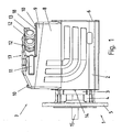
- FIG. 1 shows a converter motor 1 in side view.
- a tubular outer housing 2 coaxially surrounds a tubular inner housing 3.
- the inner housing 3 contains the motor unit of the converter motor 1.
- the stator of the motor unit is arranged in the inner housing 3 and is frictionally held by this.
- the inner housing 3 is closed on the drive side of the motor unit by an A-position plate 4, which merges into a gear flange 5.
- the drive side of the motor shaft 15 protrudes through the transmission flange 5 for connection to the driving shaft of a transmission.
- the outer housing 2 is closed in a grid like manner with a fan cover 6 attached as a cover.
- Inner housing 3 is fixedly connected via webs 14 to the outer housing 2.
- Inner casing 3 and outer casing 2 are made of a common casting.
- the material selected is aluminum.
- connection box 7 On the upper side of the outer housing 2, a terminal box 7 is arranged.
- the connection box 7 comprises a top part designed as a terminal box cover 9 which is placed on a lower part, wherein the lower part is formed from a terminal box projection 8 and a region of the outer housing 2.
- the terminal box attachment 8 is made in one piece with the outer housing 2 and surrounds a region of the outer housing 2, which forms the bottom of the connection box 7.
- the terminal box approach 8 extends substantially over the entire axial length of the outer housing. 2
- the terminal box lid 9 is fastened by screws 10 on the terminal box approach.
- the terminal box approach 8 has a sloping upper edge, the height above the outer housing 2 on the drive side is higher than at the opposite end of the inverter motor 1.
- a skew is formed with a sloping height profile, which decreases along the motor axis away from the drive side.
- the terminal box lid 9 has a corresponding skew.
- the angles of the skew with the side walls in the lower part and the upper part are the same, so that the side walls are essentially flat in one another.
- a step is formed, which is formed by the top cover 17 and a shoulder 18 and a side surface connecting both surfaces. Lid top 17 and paragraph 18 thus each define a plateau of different heights, the heel 18 being stepped relative to the top of the lid 17.
- a height profile is formed, which is sloping in the same direction as the skew at the terminal box approach 8.
- the step comprises a side surface on which connection sockets 12, 13 are arranged for a sealing cable feed-through.
- terminal box cover 9 On opposite sides of the terminal box cover 9 each have an axially extending recessed grip 11 is formed, with which the terminal box cover 9 is removable. At the front of the terminal box cover 9 a flat chamfer 21 is further formed, which goes into the top lid 17 over.
- FIG. 2 shows a sectional view of the inverter motor FIG. 1 ,
- the rotor 34 of the motor unit of the inverter motor 1 is mounted on the motor shaft 15, the rotor 34 of the motor unit of the inverter motor 1 is mounted.
- the rotor 34 is arranged in the stator 33 of the motor unit.
- the stator 33 is inserted into a tubular stator housing 3 and secured therein.
- the stator housing 3 is closed by the A-end shield 4 and the B-end shield 40, through which the motor shaft 15 is guided.
- a gear flange 5 is formed for connecting the inverter motor 1 to a device to be driven.
- This end of the motor unit is thus designed as a drive side.
- a holding brake 47 and a fan 23 are arranged at the rear, guided by the B-end shield end of the motor shaft 15, a holding brake 47 and a fan 23 are arranged.
- the Holding brake 47 includes a brake body 29, a brake disc 32, an armature disc
- the holding brake 47 in particular the area surrounding the brake disk 32, are sealed by a circumferential brake seal 39.
- the brake seal 39 has a centrally circumferential fold and is thus variable in length in the axial direction.
- the holding brake 47 is sealed on the motor shaft 15 by a shaft seal 38 with one or more shaft sealing rings.
- the brake connection cables 41 are guided within the sealed area by the B-end shield.
- the fan 23 has a hub 25 for attachment to the motor shaft 15.
- the fan wheel also has a conically running main body 26, on which wings 24 are formed.
- wings 24 are formed in at least one wing 24, an axially extending mounting hole is formed for attachment of a donor flag, not shown.
- the stator housing 3 is surrounded by a tubular outer housing 2.
- the outer housing 2 is partially housing-forming for the fan wheel 23 and holding brake 47.
- the outer housing 2 is closed at one axial end by a fan cover 6 designed as a cover. The fan cover 6 thus forms together with the outer housing 2, the fan cover of the inverter motor.
- a guide ring 28 for the air moved through the fan is formed on the inside.
- the guide ring is rotationally symmetrical and opens conically towards the interior of the converter motor.
- the opening angle of the guide ring is set up such that two fan blades 24 together with the base body 26 of the fan wheel 23 form an air channel narrowing in axial section.
- nozzle-like channels are formed, which move cooling air into a flow channel 22 formed between the first tubular part, the outer housing 2, and the second tubular part, the stator housing 3, upon rotation of the fan wheel 23.
- the flow channel 22 has an annular cross-section and extends over the entire axial length of the stator housing 3.
- An outwardly terminated port channel 48 connects the interior of the junction box 7 to the interior of the stator housing 3 for passing the connection cables for the stator and the brake connection cable 41.
- the stator housing 3 is connected to the outer housing 2 via radially extending webs 14, which break through the flow channel 22.
- Stator housing 3, webs 14 and outer housing 2 are made of an aluminum casting.
- the webs 14 therefore have a thickness which decreases in an axial direction in order to be able to remove the inner mold used during the casting.
- the terminal box 7 has a terminal box approach 8 and a terminal box cover 9.
- the terminal box approach 8 is formed on the outer housing 2 and with this in one piece.
- the terminal box 7 is housing-forming for the converter electronics 35 of the converter motor 1.
- the converter electronics 35 comprises on a circuit board 36 at least the power output stage with power devices 37 in the form of IGBTs.
- the inverter electronics 35 is equipped with a rectifier stage and a DC link capacitor on a further, not shown, printed circuit board.
- planar contact surfaces are respectively formed in a first cooling area 20 and in a second cooling area 21 for cooling circuit parts of the converter electronics 35.
- the contact surfaces are finer than the remaining cast body and have a significantly lower surface roughness, which is a good thermal Connection possible.
- the power devices 37 are placed in a row surface, wherein between power components 37 and bearing surface thermal compound is applied.
- the converter electronics 35 is partially filled with a heat-conducting potting compound, via which further electronic components of the converter electronics are thermally connected to the outer housing 2.
- the cooling of the inner surface of the outer housing by the cooling air in the flow channel 22 thus causes an improved cooling of the converter electronics 35 on the Enteriermungs Schemee 20, 21, especially the power devices 37.
- the outer housing 2 thus provides a large tubular cooling surface ready, which is covered by the cooling air. Additional cooling ribs are therefore unnecessary.
- FIG. 3 shows another view of the inverter motor FIG. 1 ,
- the stator housing 3 is connected to the outer housing 2 via a radially extending web 45, in which a bore for a connecting screw between the A-bearing plate 4 and B-bearing plate 40 is arranged.
- the web 45 runs in the axial direction in a reinforcing rib 44, which surrounds the region of the outer housing 2, the brake body 29 and fan 23, amplified.
- a bore is provided for receiving a screw 43, with which the fan cover 6 is attached to the outer housing 2.
- the web 45 and the reinforcing flu 44 have a decreasing towards the fan end thickness.
- the reinforcing rib 44 is also formed with a decreasing in this direction radial height.
- the inner surface of the outer housing 2 with the webs 14, 45 and reinforcing ribs 44 thus opens slightly conically towards the fan end.
- Corresponding webs 45 with reinforcing ribs 44 and screws 43 are arranged in the remaining rounded corner regions of the outer housing 2.
- a manual release lever 42 is provided for releasing the holding brake 47.
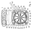
- FIG. 4 shows the rear view of the inverter motor FIG. 1 with removed fan cover.
- the outer housing 2 has a square cross-section with rounded corners. In each corner, a web 45 is arranged with a reinforcing rib 44. Between the reinforcing ribs 44 in the middle of the edge line of the square cross section, a web 14 for connecting the stator housing 3 to the outer housing 2 is arranged on three sides. The webs 14 are thinner than the webs 45 and take no hole for mounting screws of the end shields. The webs 14 extend only over the axial length of the stator housing third
- the thicker webs 45 bridge a greater distance between the tubular housing parts than the thinner web 14.
- the webs 14, 45 break through the flow channel 22 and thus form a regular pattern of individual, axially extending passages for cooling air.
- an outwardly-sealed terminal channel 48 which connects the interior of the terminal box 7 to the interior of the stator housing 3 for passing the connection cables for the stator and the brake connecting cable.
- the wings 24 are arranged on the main body 26 of the fan nine wings 24 are arranged.
- the wings 24 each extend in an axial plane.
- mounting holes 27 are introduced for concentric attachment of an annular disc with magnetized areas whose magnetization changes along the circumference.
- an encoder can be mounted, which detects these during rotation of the motor shaft 15 changing magnetization and detects the speed and / or the rotation angle.
- Various discs are mountable, which allow a different angular resolution and / or a rotational angle detection.
- the front ends of the reinforcing ribs 44 and the edge of the outer housing 2 form a mechanical interface, on the alternative to the fan cover 6 different mounting options can be mounted.
- mounting options include the described encoder, which is integrated in a fan cover, designed as an adapter for mounting a commercial encoder fan cover with a concentric encoder flange, a forced cooling fan and a fan roof, so a tight cover against dripping water when mounting the inverter motor with vertically extending Motor shaft 15.
- a series of inverter motors is provided in which different mounting options are mounted on a uniform converter motor housing of outer housing, stator housing and terminal box in variants depending on requirements.
- the holding brake is ventilated with a manual release lever 42, which is guided through a radially oriented opening 46 in the outer housing 2.
- FIG. 5 shows the fan cover 6 of the inverter motor FIG. 1
- a base plate 50 is provided with a rim 51 which describes a square with rounded corners and slightly outwardly bent edges.
- the shape of the base plate is chosen so that the fan cover 6 on the edge of the outer housing 2 in FIG. 4 fits.
- the base plate is flat, whereby a straight completion of the outer housing 2 of the inverter motor is achieved.
- the screws 43 in FIG. 3 and 4 are guided through mounting holes 53 and screwed into the bores of the reinforcing ribs 44.
- a guide ring 28 is mounted, which opens conically away from the base plate 50.
- the guide ring 28 is integrally formed with the base plate 50 and defines a through-opened area, which is provided as an air inlet of the fan.
- the fan cover 6 is made of plastic.
- the guide ring 28 has at its upper end in the picture a maximum diameter which is less than the minimum diameter of the rim 51. Thus, it is ensured that the guide ring 28 is inserted into the outer housing 2 and the base plate 50, the outer housing 2 closes.
- the reinforcing ribs 44 end shortly before the edge of the outer housing 2 and there is a circumferential receptacle for the fan cover 6 formed on the inside of the outer housing 2, so that the fan cover 6 is completely retractable in the outer housing 2.
Landscapes
- Engineering & Computer Science (AREA)
- Power Engineering (AREA)
- Microelectronics & Electronic Packaging (AREA)
- Motor Or Generator Cooling System (AREA)
- Motor Or Generator Frames (AREA)
- Connection Of Motors, Electrical Generators, Mechanical Devices, And The Like (AREA)
Description
- Die Erfindung betrifft eine Lüfterhaube, einen Umrichtermotor und eine Baureihe von Umrichtermotoren.
- Unter Umrichtermotor wird in dieser Schrift eine elektrisch betriebene Antriebseinheit verstanden, die zumindest eine Motoreinheit und eine elektronische Baugruppe, die Umrichtereinheit, zur Ansteuerung der Motoreinheit, insbesondere zur Regelung der Drehzahl und/oder des Drehmoments, umfasst. Die Motoreinheit kann hierbei einen permanenterregten Rotor, einen Käfigläufer oder eine Kombination von beidem umfassen oder als Außenläufer ausgebildet sein.
- Aus
FR 2 608 32 A - Aus
EP 0 681 360 A2 ist ein Kompaktantrieb aus Motor und Steuerung bekannt, wobei eine Trägerbraugruppe vorhanden ist, die eine Steuerungsbaugruppe trägt und gleichzeitig als Leitsystem für einen Kühlluftstrom ausgebildet ist. - Aus
US 5 763 969 A ist ein integriertes System aus Elektromotor und Antrieb mit einem Hilfskühlmotor und einer asymmetrischen Wärmesenke bekannt - Aus
EP 0 456 169 A1 ist ein frequenzumrichtergespeister Elektromotor bekannt, wobei die innerhalb eines Leistungsteils in einem Klemmenkasten entstehende Abwärme durch eine Gehäusedurchbrechung an der Unterseite des Klemmenkastens abgeführt wird. - Aus
WO2006/108550A1 ist ein Elektromotor bekannt, bei welchem Befestigungsmittel als stromlinienförmige Verdickungen von Kühlrippen ausgeführt sind. - Der Erfindung liegt die Aufgabe zugrunde, die Herstellungskosten für einen Umrichtermotor zu senken.
- Erfindungsgemäß wird die Aufgabe bei der Lüfterhaube nach den in Anspruch 1 angegebenen Merkmalen und, bei dem Umrichtermotor nach den in Anspruch 7 angegeben Merkmalen angegebenen Merkmalen gelöst.
- Wichtige Merkmale der Erfindung einer Lüfterhaube sind, dass ein erstes rohrförmiges Teil an einem axialen Ende durch einen Deckel verschlossen ist und am ersten rohrförmigen Teil ein Anschlusskasten, insbesondere seitlich, ausgebildet ist. Mit rohrförmig wird in dieser Schrift allgemein ein im Wesentlichen um eine Achse diskret oder kontinuierlich drehsymmetrisch, im Inneren hohl und insgesamt mit einer im Vergleich zum Durchmesser dünnen Wandstärke versehen ausgebildetes Teil bezeichnet. Eine Lüfterhaube wird geteilt in ein erstes rohrförmiges Teil, die Seitenwand, und einen Deckel. Die Seitenwand der Lüfterhaube ist somit vorteilhaft aus einem anderen Material fertigbar als der Deckel. Beispielsweise ist für die Seitenwand ein metallischer Werkstoff verwendbar und für den Deckel Kunststoff. Die Seitenwand ist daher zur Wärmeleitung nutzbar, während die Fertigung des Deckels aus Kunststoff eine Gewichtsreduzierung und eine Reduzierung der Materialkosten bewirkt. Vorzugsweise ist das rohrförmige Teil aus Aluminiumguss hergestellt und stabil gegen Verformungen ausgebildet. Weiter ist der Anschlusskasten an der Lüfterhaube befestigt und vorteilhaft in die Eigenlüftung eines Motors integriert. Der Anschlusskasten kann daher vorteilhaft die Elektronik eines Umrichters aufnehmen, die durch die Integration des Anschlusskastens in die Lüfterhaube entwärmt wird. Somit ist die Entwärmung eines Umrichtermotors durch den Einsatz einer erfindungsgemäßen Lüfterhaube verbessert. Eine zusätzliche Ausbildung von Kühlrippen oder ein zusätzlicher Lüfter für die Elektronikkühlung sind verzichtbar, und die Herstellungskosten werden reduziert. Durch die mehrteilige Ausbildung ist der Deckel bei Bedarf zur Wartung abnehmbar oder sogar ersetzbar durch eine Motoranbauoption. Es ist also eine Baureihe bildbar, wobei durch die Wiederverwendung von Teilen, hier dem Gehäuse, der Motoreinheit und der Umrichterelektronik, Lagerhaltungskosten und Transportkosten eingespart werden.
- Erfindungsgemäß weist der Deckel einen Bereich mit Ausnehmungen auf. Die Ausnehmungen bilden vorzugsweise einen durchbrochenen Bereich. Von Vorteil ist dabei, dass ein Lufteinlass ausgebildet ist, durch den Kühlluft zu einer mit dem Anschlusskasten verbundenen Fläche strömen kann.
- Erfindungsgemäß umfasst der Deckel eine Grundplatte, auf der ein Luftleitring befestigt ist, wobei der Ansatzbereich des Luftleitrings auf der Grundplatte den durchbrochenen Bereich begrenzt. Der Ansatzbereich des Luftleitrings umfasst den Ansatzkreis, an dem der Luftleitring in die Grundplatte übergeht. Von Vorteil ist dabei, dass ein möglichst großer axialer Abschnitt eines Motors durch die rohrförmig ausgebildete Seitenwand der Lüfterhaube für die Kühlung nutzbar ist, denn der Deckel weist nur eine geringe axiale Dicke auf. Von Vorteil ist weiterhin, dass die Lüfterhaube aus einem stabilen rohrförmigen Teil aus Metall und einem kostengünstigen Deckel aus Kunststoff fertigbar ist. Durch den Luftleitring wird die Kühlluft besser geführt. Die einstückige Ausführung von Luftleitring und Grundplatte verringert die Montagekosten. Es sind weiter unterschiedliche Lüfterräder mit unterschiedlichen Flügelformen im Lüfter einsetzbar, wobei jeweils ein passender Deckel mit der Flügelform angepasstem Luftleitring auf das rohrförmige Teil gesetzt wird.
- Bei einer vorteilhaften Ausgestaltung ist der minimale Durchmesser der Grundplatte größer als der maximale Durchmesser des Luftleitrings. Somit ist der Luftleitring in das Innere des ersten rohrförmigen Teils einsetzbar. Er ist daher geschützt, und die axiale Baulänge des Umrichtermotors ist vermindert.
- Bei einer vorteilhaften Ausgestaltung erstreckt sich der Anschlusskasten über die axiale Länge des rohrförmigen Teils. Von Vorteil ist dabei, dass genügend Platz für die Aufnahme einer Umrichterelektronik vorhanden ist und die Umrichterelektronik zur Entwärmung die gesamte Länge des rohrförmigen Teils nutzen kann. Insbesondere ist die direkte thermische Anbindung der Umrichterelektronik über einen großen Bereich an das rohrförmige Teil möglich, wodurch die Entwärmung verbessert ist und wodurch eine Entwärmung mittels Fremdlüfter oder Zusatzkühler entfallen kann. Auch die Fertigung aufwendiger Kühlrippen oder Kühlfinger kann entfallen, weil eine aus Aluminiumguss hergestellte Seitenwand einer Lüfterhaube genügend Oberfläche und Material bereitstellt, um eine ausreichende Entwärmung sicherzustellen.
- Bei einer vorteilhaften Ausgestaltung weist das rohrförmige Teil eine im Wesentlichen quadratische Grundform auf, wobei in den abgerundeten Ecken auf der Innenseite des rohrförmigen Teils jeweils eine axial im Wesentlichen über die gesamte Länge des rohrförmigen Teils verlaufende Verstärkungsrippe angeordnet ist. Vorzugsweise weisen die Verstärkungsrippen an dem einen axialen Ende Bohrlöcher oder andere Befestigungsmittel zur Befestigung des Deckels auf. Von Vorteil ist dabei, dass eine stabile, belastbare mechanische Schnittstelle geschaffen ist zur Montage von Motoroptionen als Alternative zum einfachen Deckel. Das rohrförmige Teil ist vorzugsweise aus Aluminiumguss hergestellt.
- Bei einer vorteilhaften Ausgestaltung ist an der Innenseite des Anschlusskastenbodens eine plane Auflagefläche ausgebildet zur Entwärmung eines Leistungsbauelements. Die Auflagefläche ist vorzugsweise gefräst oder geschliffen. Somit sind die IGBTs der Umrichterelektronik besonders gut an das rohrförmige Teil thermisch angebunden. Das rohrförmige Teil dient daher der Wärmeaufspreizung von den Leistungsbauelementen an die Umgebung.
- Wichtige Merkmale der Erfindung sind, dass der Umrichtermotor eine erfindungsgemäße Lüfterhaube umfasst, deren Anschlusskasten gehäusebildend für die Umrichterelektronik ist. Von Vorteil ist dabei, dass die Umrichterelektronik über einen großflächig ausgebildeten Gehäuseteil entwärmt wird, wobei die inneren Oberflächen dieses Gehäuseteils von der Kühlluft des Lüfters überstrichen werden. Somit ist die Kühlleistung der Elektronikentwärmung erhöht. Insbesondere sind Kühlrippen am Gehäuse der Umrichterelektronik verzichtbar, und es sind glatte, leicht zu reinigende Oberflächen ausbildbar. Von Vorteil ist weiterhin, dass der Deckel aus kostengünstigem Kunststoff fertigbar und unter den Rand des ersten rohrförmigen Teils, also der Seitenwand der Lüfterhaube versenkbar ist. Somit ist die Lüfterhaube zweigeteilt aufbaubar. Es wird ein stabiles Teil, das weitere Umrichtermotorteile, beispielsweise den Anschlusskasten, fest mit dem Stator verbindet, mit einem kostengünstigen, austauschbaren, leichten Teil kombiniert.
- Bei einer vorteilhaften Ausgestaltung ist mindestens ein Leistungsbauelement der Endstufe der Umrichterelektronik auf der planen Auflagefläche zur Entwärmung aufgelegt. Von Vorteil ist dabei, dass ein möglichst kurzer Abstand zwischen den Leistungsbauelementen als Wärmequelle und dem Luftstrom vom Lüfter als Wärmesenke bereitgestellt ist.
- Bei einer vorteilhaften Ausgestaltung ist das erste rohrförmige Teil der Lüfterhaube gehäusebildend für ein Lüfterrad und eine Haltebremse. Lüfterrad und Haltebremse sind somit vorteilhaft abschließbar durch den aufgesetzten Deckel und damit einer Wartung leicht zugänglich. Vorzugsweise umgibt das erste rohrförmige Teil der Lüfterhaube ein zweites rohrförmiges Teil, das gehäusebildend für den Stator des Umrichtermotors ist. Es ist zwischen erstem rohrförmigen Teil und zweitem rohrförmigen Teil ein im Querschnitt ringförmiger Strömungskanal ausgebildet, der den zweiten rohrförmigen Teil umgibt, wobei Stator und Haltebremse dicht gegen den Strömungskanal abgeschlossen sind. Vorzugsweise umfasst der Strömungskanal den Bereich, der auf der Innenseite des rohrförmigen Teils gegenüber der planen Auflagefläche am Boden des Anschlusskastens liegt. Somit ist der metallische Bereich der Lüfterhaube nutzbar zur Entwärmung des Umrichters. Diese Entwärmung wird verbessert durch die an der Innenseite der Seitenwand der Lüfterhaube vorbeistreichende Luft. Der dichte Abschluss von Stator und Haltebremse verringert Verschmutzungen durch die Kühlluft, und der Wartungsaufwand wird verringert.
- Bei einer vorteilhaften Ausgestaltung sind das erste rohrförmige Teil und das zweite rohrförmige Teil aus einem Gussteil gefertigt, wobei radial verlaufende Stege das erste rohrförmige Teil mit dem zweiten rohrförmigen Teil verbinden. Somit ist das gesamte Gehäuse aus Statorgehäuse und Lüfterhauben-Seitenwand und Anschlusskastenansatz aus einem Gussteil fertigbar. Montagekosten für den Zusammenbau von Einzelteilen entfallen somit weitestgehend. Durch die einstückige Ausbildung des Gehäuses aus Gussteilen ist somit eine große Kühlfläche ohne ungünstige Wärmeübergänge ausgebildet. Obwohl Statorgehäuse und Elektronikgehäuse miteinander verbunden sind, sind sie durch die Ausbildung gekühlter Verbindungsstege thermisch entkoppelt. Auch hierdurch ist ein verminderter Kühlleistungsbedarf erreicht.
- Bei einer vorteilhaften Ausgestaltung laufen die Verstärkungsrippen auf der Innenseite des ersten rohrförmigen Teils am dem einen axialen Ende gegenüberliegenden anderen axialen Ende in radial verlaufende Stege aus, wobei diese Stege das erste rohrförmige Teil mit dem zweiten rohrförmigen Teil verbinden und Bohrungen für Befestigungsschrauben für die am zweiten rohrförmigen Teils angeordneten Lagerschilde des Motors des Umrichters aufweisen. Somit ist eine Oberflächenform bereitgestellt, die mit wenigen Arbeitsschritten fertigbar ist. Verlorene Formen beim Gießen sind vermieden.
- Bei einer vorteilhaften Ausgestaltung ist der Innenraum des Anschlusskastens mit dem Innenraum des zweiten rohrförmigen Teils durch einen Anschlusskanal zur Durchführung der Statoranschlusskabel verbunden, wobei der Anschlusskanal dicht abgeschlossen ist gegen den Strömungskanal. Der Anschlusskanal ist vorzugsweise beim Gießen ausgebildet. Der dichte Abschluss des Anschlusskanals verhindert beispielsweise eine Beschädigung des Stators durch eindringende Feuchtigkeit.
- Bei einer vorteilhaften Ausgestaltung ist eine Haltebremse mit einem Handlüfthebel vorgesehen, wobei der Handlüfthebel durch eine Öffnung im ersten rohrförmigen Teil geführt ist. Somit ist der Umrichtermotor auch im unbestromten Zustand bewegbar, beispielsweise bei einer Wartung der Maschine oder Anlage, die durch den Umrichtermotor angetrieben werden soll. Eine Kupplung ist somit verzichtbar.
- Weitere Vorteile ergeben sich aus den Unteransprüchen.
- Die Erfindung wird nun anhand von Abbildungen näher erläutert:
- Es zeigt
-
Figur 1 einen Umrichtermotor mit Motoranschlusskasten, -
Figur 2 eine Schnittansicht des Umrichtermotors ausFigur 1 , -
Figur 3 eine weitere Schnittansicht des Umrichtermotors ausFigur 1 , -
Figur 4 eine Ansicht des Umrichtermotors ausFigur 1 von hinten und -
Figur 5 eine erfindungsgemäße Lüfterabdeckung.
-
-
Figur 1 zeigt einen Umrichtermotor 1 in Seitenansicht. Ein rohrförmiges Außengehäuse 2 umgibt koaxial ein rohrförmiges Innengehäuse 3. Das Innengehäuse 3 enthält die Motoreinheit des Umrichtermotors 1. Der Stator der Motoreinheit ist in dem Innengehäuse 3 angeordnet und wird durch dieses kraftschlüssig gehalten. Das Innengehäuse 3 ist auf der Antriebsseite der Motoreinheit durch einen A-Lageschild 4 abgeschlossen, der in einen Getriebeflansch 5 übergeht. Die Antriebsseite der Motorwelle 15 ragt durch den Getriebeflansch 5 hindurch zur Verbindung mit der eintreibenden Welle eines Getriebes. Am gegenüberliegenden Ende des Umrichtermotors 1 ist das Außengehäuse 2 mit einer als Deckel aufgesetzten Lüfterabdeckung 6 gitterartig verschlossen. - Das Innengehäuse 3 ist über Stege 14 mit dem Außengehäuse 2 fest verbunden. Innengehäuse 3 und Außengehäuse 2 sind aus einem gemeinsamen Gussteil gefertigt. Vorzugsweise wird als Material Aluminium gewählt.
- Auf der Oberseite des Außengehäuses 2 ist ein Anschlusskasten 7 angeordnet. Der Anschlusskasten 7 umfasst ein als Anschlusskastendeckel 9 ausgebildetes Oberteil, das auf ein Unterteil aufgesetzt wird, wobei das Unterteil aus einem Anschlusskastenansatz 8 und einem Bereich des Außengehäuses 2 gebildet wird. Der Anschlusskastenansatz 8 ist einstückig mit dem Außengehäuse 2 ausgeführt und umgibt einen Bereich des Außengehäuses 2, der den Boden des Anschlusskastens 7 bildet. Der Anschlusskastenansatz 8 erstreckt sich im Wesentlich über die gesamte axiale Länge des Außengehäuses 2.
- Der Anschlusskastendeckel 9 wird durch Schrauben 10 auf dem Anschlusskastenansatz befestigt.
- Der Anschlusskastenansatz 8 weist eine schräg verlaufende Oberkante auf, deren Höhe über dem Außengehäuse 2 auf der Antriebsseite höher ist als am gegenüberliegenden Ende des Umrichtermotors 1. Somit ist eine Schrägung mit einem abfallender Höhenverlauf ausgebildet, der entlang der Motorachse von der Antriebsseite weg abnimmt. Der Anschlusskastendeckel 9 weist eine entsprechende Schrägung auf. Insbesondere sind die Winkel der Schrägung mit den Seitenwänden bei Unterteil und Oberteil gleich, so dass die Seitenwände im Wesentlichen eben ineinander über gehen.
- Im oberen Bereich des Anschlusskastendeckels 9 ist eine Stufe ausgebildet, die durch die Deckeloberseite 17 und einen Absatz 18 sowie eine beide Flächen verbindende Seitenfläche gebildet wird. Deckeloberseite 17 und Absatz 18 definieren somit jeweils ein Plateau unterschiedlicher Höhe, wobei der Absatz 18 gegenüber der Deckeloberseite 17 abgestuft ist. Durch die Stufe wird ein Höhenverlauf gebildet, der in der gleichen Richtung wie die Schrägung am Anschlusskastenansatz 8 abfallend verläuft. Die Stufe umfasst eine Seitenfläche, auf der Anschlussstutzen 12, 13 für eine dichtende Kabeldurchführung angeordnet sind.
- An gegenüberliegenden Seiten des Anschlusskastendeckels 9 ist jeweils eine axial verlaufende Griffmulde 11 ausgebildet, mit denen der Anschlusskastendeckel 9 abnehmbar ist. An der Vorderseite des Anschlusskastendeckels 9 ist weiterhin eine flächige Abschrägung 21 ausgebildet, die in die Deckeloberseite 17 über geht.
-
Figur 2 zeigt eine Schnittansicht des Umrichtermotors ausFigur 1 . Auf der Motorwelle 15 ist der Rotor 34 der Motoreinheit des Umrichtermotors 1 angebracht. Der Rotor 34 ist im Stator 33 der Motoreinheit angeordnet. Der Stator 33 ist in ein rohrförmig ausgebildetes Statorgehäuse 3 eingeschoben und in diesem befestigt. Das Statorgehäuse 3 ist durch den A-Lagerschild 4 und den B-Lagerschild 40 verschlossen, durch die die Motorwelle 15 geführt ist. Am A-Lagerschild 4 ist ein Getriebeflansch 5 ausgebildet zum Anschluss des Umrichtermotors 1 an eine anzutreibende Vorrichtung. Dieses Ende der Motoreinheit ist somit als Antriebseite ausgebildet. Am rückwärtigen, durch den B-Lagerschild geführten Ende der Motorwelle 15 sind eine Haltebremse 47 und ein Lüfterrad 23 angeordnet. Die Haltebremse 47 umfasst einen Bremskörper 29, eine Bremsscheibe 32, eine Ankerscheibe 31 und Spulen 30, mit denen die Ankerscheibe 31 gelüftet wird zur Freigabe der Haltebremse 47. - Die Haltebremse 47, insbesondere der die Bremsscheibe 32 umgebende Bereich, sind durch eine umlaufende Bremsendichtung 39 abgedichtet. Die Bremsendichtung 39 weist eine mittig umlaufende Falte auf und ist somit in axialer Richtung längenveränderlich. Die Haltebremse 47 ist auf der Motorwelle 15 durch eine Wellendichtung 38 mit einem oder mehreren Wellendichtringen abgedichtet. Die Bremsenanschlusskabel 41 sind innerhalb des abgedichteten Bereichs durch den B-Lagerschild geführt.
- Das Lüfterrad 23 weist eine Nabe 25 zur Befestigung auf der Motorwelle 15 auf. Das Lüfterrad weist weiter einen konisch verlaufenden Grundkörper 26 auf, an dem Flügel 24 ausgebildet sind. In mindestens einem Flügel 24 ist ein axial verlaufendes Befestigungsloch ausgebildet zur Befestigung einer nicht dargestellten Geberfahne.
- Das Statorgehäuse 3 wird von einem rohrförmig ausgebildeten Außengehäuse 2 umgeben. Das Außengehäuse 2 ist teilweise gehäusebildend für das Lüfterrad 23 und Haltebremse 47. Das Außengehäuse 2 ist an einem axialen Ende durch eine als Deckel ausgebildete Lüfterabdeckung 6 verschlossen. Die Lüfterabdeckung 6 bildet somit gemeinsam mit dem Außengehäuse 2 die Lüfterhaube des Umrichtermotors.
- An der Lüfterabdeckung 6 ist auf der Innenseite ein Leitring 28 für die durch den Lüfter bewegte Luft ausgebildet. Der Leitring ist rotationssymmetrisch ausgeformt und öffnet sich konisch zum Inneren des Umrichtermotors hin. Der Öffnungswinkel des Leitrings ist so eingerichtet, dass jeweils zwei Lüfterflügel 24 gemeinsam mit dem Grundkörper 26 des Lüfterrads 23 einen sich im Axialschnitt verengenden Luftkanal bilden. Somit sind düsenartige Kanäle geformt, die bei einer Rotation des Lüfterrads 23 Kühlluft in einen zwischen dem ersten rohrförmigen Teil, dem Außengehäuse 2, und dem zweiten rohrförmigen Teil, dem Statorgehäuse 3, gebildeten Strömungskanal 22 bewegen. Der Strömungskanal 22 weist einen ringförmigen Querschnitt auf und erstreckt sich über die gesamte axiale Länge des Statorgehäuses 3. Somit wird zum einen der Stator 33 und zum anderen die Innenseite des Außengehäuses 2 gekühlt und zum dritten eine Wärmesperre zwischen Stator 33 und Anschlusskasten 7 eingerichtet.
- Durch die beschriebenen Dichtungsmaßnahmen sind das Innere des Stators 33 und das Innere der Haltebremse 47 gegen den Kühlluftstrom abgedichtet und vor Verschmutzung geschützt. Ein nach außen abgeschlossener Anschlusskanal 48 verbindet das Innere des Anschlusskastens 7 mit dem Inneren des Statorgehäuses 3 zur Durchführung der Anschlusskabel für den Stator und der Bremsenanschlusskabel 41.
- Das Statorgehäuse 3 ist mit dem Außengehäuse 2 über radial verlaufende Stege 14 verbunden, die den Strömungskanal 22 durchbrechen. Statorgehäuse 3, Stege 14 und Außengehäuse 2 sind aus einem Aluminiumgussteil gefertigt. Die Stege 14 weisen daher eine in eine axiale Richtung abnehmende Dicke auf, um die beim Guss eingesetzte Innenform entfernen zu können.
- Der Anschlusskasten 7 weist einen Anschlusskastenansatz 8 und einen Anschlusskastendeckel 9 auf. Der Anschlusskastenansatz 8 ist am Außengehäuse 2 und mit diesem einstückig ausgebildet. Der Anschlusskasten 7 ist gehäusebildend für die Umrichterelektronik 35 des Umrichtermotors 1. Die Umrichterelektronik 35 umfasst auf einer Leiterplatte 36 zumindest die Leistungsendstufe mit Leistungsbauelementen 37 in Form von IGBTs. Zusätzlich ist auf einer weiteren, nicht dargestellten Leiterplatte die Umrichterelektronik 35 mit einer Gleichrichterstufe und einem Zwischenkreiskondensator ausgerüstet.
- Auf der Innenseite des Anschlusskastenbodens sind in einem ersten Entwärmungsbereich 20 und in einem zweiten Entwärmungsbereich 21 jeweils plane Auflageflächen ausgebildet zur Entwärmung von Schaltungsteilen der Umrichterelektronik 35. Die Auflageflächen sind feiner bearbeitet als der restliche Gusskörper und weist eine deutlich geringerer Oberflächenrauhigkeit auf, die eine gute thermische Anbindung ermöglicht. Auf die Auflagefläche des ersten Entwärmungsbereichs 20 sind die Leistungsbauelemente 37 in einer Reihe flächig aufgelegt, wobei zwischen Leistungsbauelementen 37 und Auflagefläche Wärmeleitpaste aufgetragen ist. Die Umrichterelektronik 35 ist teilweise mit einer wärmeleitenden Vergussmasse ausgegossen, über die weitere elektronische Bauelemente der Umrichterelektronik thermisch an das Außengehäuse 2 angebunden sind.
- Die Kühlung der Innenfläche des Außengehäuses durch die Kühlluft im Strömungskanal 22 bewirkt somit eine verbesserte Entwärmung der Umrichterelektronik 35 über die Entwärmungsbereiche 20, 21, besonders der Leistungsbauelemente 37. Das Außengehäuse 2 stellt somit eine große rohrförmige Kühlfläche bereit, die von der Kühlluft überstrichen wird. Zusätzliche Kühlrippen sind somit verzichtbar.
-
Figur 3 zeigt eine weitere Ansicht des Umrichtermotors ausFigur 1 . Das Statorgehäuse 3 ist mit dem Außengehäuse 2 über einen radial verlaufenden Steg 45 verbunden, in dem eine Bohrung für ein Verbindungsschraube zwischen A-Lagerschild 4 und B-Lagerschild 40 angeordnet ist. Der Steg 45 läuft in axialer Richtung in eine Verstärkungsrippe 44 aus, die den Bereich des Außengehäuses 2, der Bremskörper 29 und Lüfterrad 23 umgibt, verstärkt. Am Ende der Verstärkungsrippe 44 ist eine Bohrung vorgesehen zur Aufnahme einer Schraube 43, mit der die Lüfterabdeckung 6 am Außengehäuse 2 befestigt ist. - Der Steg 45 und die Verstärkungsgrippe 44 weisen eine zum Lüfterende hin abnehmende Dicke auf. Die Verstärkungsrippe 44 ist zudem mit einer in dieser Richtung abnehmenden radialen Höhe ausgebildet. Die Innenfläche des Außengehäuses 2 mit den Stegen 14, 45 und Verstärkungsrippen 44 öffnet sich somit leicht konisch zum Lüfterende hin. Somit ist ein in der Gussfertigung verwendeter Gusskörper nach dem Guss entfernbar.
- Entsprechende Stege 45 mit Verstärkungsrippen 44 und Schrauben 43 sind in den übrigen abgerundeten Eckbereichen des Außengehäuses 2 angeordnet.
- Zum Lüften der Haltebremse 47 ist ein Handlüfthebel 42 vorgesehen.
-
Figur 4 zeigt die rückwärtige Ansicht des Umrichtermotors ausFigur 1 mit abgenommener Lüfterabdeckung. Das Außengehäuse 2 weist einen quadratischen Querschnitt mit abgerundeten Ecken auf. In jeder Ecke ist ein Steg 45 mit einer Verstärkungsrippe 44 angeordnet. Zwischen den Verstärkungsrippen 44 in der Mitte der Kantenlinie des quadratischen Querschnitts ist auf drei Seiten ein Steg 14 zur Verbindung des Statorgehäuses 3 mit dem Außengehäuse 2 angeordnet. Die Stege 14 sind dünner ausgebildet als die Stege 45 und nehmen keine Bohrung für Befestigungsschrauben der Lagerschilde auf. Die Stege 14 erstrecken sich lediglich über die axiale Länge des Statorgehäuses 3. - Die dickeren Stege 45 überbrücken einen größeren Abstand zwischen den rohrförmigen Gehäuseteilen als die dünneren Steg 14. Die Stege 14, 45 durchbrechen den Strömungskanal 22 und bilden somit ein regelmäßiges Muster von einzelnen, axial verlaufenden Durchlässen für Kühlluft. An der Oberseite des runden Statorgehäuses 3 ist ein nach außen abgeschlossener Anschlusskanal 48 ausgeformt, der das Innere des Anschlusskastens 7 mit dem Inneren des Statorgehäuses 3 verbindet zur Durchführung der Anschlusskabel für den Stator und der Bremsenanschlusskabel.
- Auf dem Grundkörper 26 des Lüfterrads sind neun Flügel 24 angeordnet. Die Flügel 24 verlaufen jeweils in einer Axialebene. Somit ist eine drehrichtungsunabhängige Funktion des Lüfters sichergestellt. In drei im Winkel von 120° zueinander angeordneten Flügeln 24 sind Befestigungslöcher 27 eingebracht zur konzentrischen Befestigung einer ringförmigen Scheibe mit magnetisierten Bereichen, deren Magnetisierung entlang des Umfangs wechselt. Somit ist statt der Lüfterabdeckung ein Geber montierbar, der diese bei Rotation der Motorwelle 15 wechselnde Magnetisierung erfasst und daraus die Drehzahl und/oder den Drehwinkel erfasst. Verschiedene Scheiben sind montierbar, die eine unterschiedliche Winkelauflösung und/oder eine Drehwinkelerfassung ermöglichen.
- Die Stirnenden der Verstärkungsrippen 44 und der Rand des Außengehäuses 2 formen eine mechanische Schnittstelle aus, auf der alternativ zu der Lüfterabdeckung 6 verschiedene Anbauoptionen montierbar sind. Beispiele solcher Anbauoptionen umfassen den beschriebenen Geber, der in eine Lüfterabdeckung integriert ist, eine als Adapter für den Anbau eines handelsüblichen Gebers ausgebildete Lüfterabdeckung mit einem konzentrischen Geberflansch, einen Fremdlüfter und ein Lüfterdach, also eine dichte Abdeckung gegen Tropfwasser bei Montage des Umrichtermotors mit vertikal verlaufender Motorwelle 15. Somit ist eine Baureihe von Umrichtermotoren bereitgestellt, bei der in Varianten je nach Anforderungen unterschiedliche Anbauoptionen an einem einheitlichen Umrichtermotorgehäuse aus Außengehäuse, Statorgehäuse und Anschlusskasten montiert werden.
- Die Haltebremse wird mit einem Handlüfthebel 42 belüftet, der durch eine radial orientierte Öffnung 46 im Außengehäuse 2 geführt ist.
-
Figur 5 zeigt die Lüfterabdeckung 6 des Umrichtermotors ausFigur 1 . Eine Grundplatte 50 ist mit einem Rand 51 versehen, der ein Quadrat mit abgerundeten Ecken und leicht nach außen gebogenen Kanten beschreibt. Die Form der Grundplatte ist so gewählt, dass die Lüfterabdeckung 6 auf den Rand des Außengehäuses 2 inFigur 4 passt. Die Grundplatte ist eben ausgeführt, wodurch ein gerader Abschluss des Außengehäuses 2 des Umrichtermotors erreicht wird. Die Schauben 43 inFigur 3 und4 werden durch Befestigungslöcher 53 geführt und in die Bohrlöcher der Verstärkungsrippen 44 eingeschraubt. - Auf der Grundplatte 50 ist ein Leitring 28 angebracht, der sich konisch von der Grundplatte 50 weg öffnet. Der Leitring 28 ist mit der Grundplatte 50 einstückig ausgebildet und begrenzt einen durch durchbrochenen Bereich, der als Lufteinlass des Lüfters vorgesehen ist. Vorzugsweise ist die Lüfterabdeckung 6 aus Kunststoff gefertigt.
- Der Leitring 28 weist an seinem im Bild oberen Ende einen maximalen Durchmesser auf, der geringer ist als der minimale Durchmesser des Randes 51. Somit ist sichergestellt, dass der Leitring 28 in das Außengehäuse 2 einsetzbar ist und die Grundplatte 50 das Außengehäuses 2 verschließt.
- Bei einer Weiterbildung enden die Verstärkungsrippen 44 kurz vor dem Rand des Außengehäuses 2 und es ist eine umlaufende Aufnahme für die Lüfterabdeckung 6 auf der Innenseite des Außengehäuses 2 ausgebildet, so dass die Lüfterabdeckung 6 ganz im Außengehäuse 2 versenkbar ist.
-
- 1
- Umrichtermotor
- 2
- Außengehäuse
- 3
- Statorgehäuse
- 4
- A-Lagerschild
- 5
- Getriebeflansch
- 6
- Lüfterabdeckung
- 7
- Anschlusskasten
- 8
- Anschlusskastenansatz
- 9
- Anschlusskastendeckel
- 10
- Schraube
- 11
- Griffmulde
- 12
- Anschlussstutzen
- 13
- Anschlussstutzen
- 14
- Steg
- 15
- Motorwelle
- 17
- Deckeloberseite
- 18
- Absatz
- 20
- Entwärmungsbereich
- 21
- Entwärmungsbereich
- 22
- Luftkanal
- 23
- Lüfterrad
- 24
- Flügel
- 25
- Nabe
- 26
- Grundkörper
- 27
- Befestigungsloch
- 28
- Leitring
- 29
- Bremsenkörper
- 30
- Spule
- 31
- Ankerscheibe
- 32
- Bremsscheibe
- 33
- Stator
- 34
- Rotor
- 35
- Umrichterelektronik
- 36
- Leiterplatte
- 37
- Leistungsbauelement
- 38
- Wellendichtung
- 39
- Bremsendichtung
- 40
- B-Lagerschild
- 41
- Bremsenanschlusskabel
- 42
- Handlüfthebel
- 43
- Schraube
- 44
- Verstärkungsrippe
- 45
- Steg
- 46
- Öffnung
- 47
- Haltebremse
- 48
- Anschlusskanal
- 50
- Grundplatte
- 51
- Rand
- 52
- Lufteinlass
- 53
- Befestigungsloch
Claims (12)
- Mehrteilige Lüfterhaube, umfassend ein rohrförmiges Teil als Seitenwand und einen Deckel,
wobei das erste rohrförmige Teil an einem axialen Ende durch den Deckel verschlossen ist und am ersten rohrförmigen Teil ein in die Lüfterhaube integrierter Anschlusskasten ausgebildet ist,
wobei der Deckel einen durchbrochenen Bereich aufweist,
dadurch gekennzeichnet, dass
der Deckel eine Grundplatte (50) umfasst,
auf der ein Luftleitring (28) befestigt ist,
wobei ein Ansatzbereich des Luftleitrings (28) auf der Grundplatte (50) den durchbrochenen Bereich begrenzt. - Lüfterhaube nach Anspruch 1,
dadurch gekennzeichnet, dass
der minimale Durchmesser der Grundplatte (50) größer ist als der maximale Durchmesser des Luftleitrings (28). - Lüfterhaube nach mindestens einem der vorangegangenen Ansprüche,
dadurch gekennzeichnet, dass
sich der Anschlusskasten über die axiale Länge des rohrförmigen Teils erstreckt. - Lüfterhaube nach mindestens einem der vorangegangenen Ansprüche,
dadurch gekennzeichnet, dass
das rohrförmige Teil eine im Wesentlichen quadratische Grundform aufweist,
wobei in den Ecken auf der Innenseite des rohrförmigen Teils jeweils eine axial im Wesentlichen über die gesamte Länge des rohrförmigen Teils verlaufende Verstärkungsrippe (44) angeordnet ist,
insbesondere wobei die Verstärkungsrippen (44) an dem einen axialen Ende Bohrlöcher zur Befestigung des Deckels aufweisen. - Lüfterhaube nach mindestens einem der vorangegangenen Ansprüche,
dadurch gekennzeichnet, dass
zur Entwärmung eines Leistungsbauelements (37) an der Innenseite des Anschlusskastenbodens eine plane Auflagefläche ausgebildet ist. - Lüfterhaube nach mindestens einem der vorangegangenen Ansprüche,
dadurch gekennzeichnet, dass
das erste rohrförmige Teil aus Aluminiumguss
und der Deckel aus Kunststoffspritzguss hergestellt sind. - Umrichtermotor (1), umfassend eine Lüfterhaube nach mindestens einem der vorangegangenen Ansprüche,
dadurch gekennzeichnet, dass
der Anschlusskasten der Lüfterhaube gehäusebildend für die Umrichterelektronik (35) ist. - Umrichtermotor (1) nach Anspruch 7,
dadurch gekennzeichnet, dass
mindestens ein Leistungsbauelement (37) der Endstufe der Umrichterelektronik (35) auf der planen Auflagefläche zur Entwärmung aufgelegt ist. - Umrichtermotor (1) nach Anspruch 7 oder 8,
dadurch gekennzeichnet, dass
das erste rohrförmige Teil der Lüfterhaube gehäusebildend für ein Lüfterrad (23) und eine Haltebremse (47) ist. - Umrichtermotor (1) nach einem der Ansprüche 7 bis 9,
dadurch gekennzeichnet, dass
das erste rohrförmige Teil der Lüfterhaube ein zweites rohrförmiges Teil umgibt,
das gehäusebildend für den Stator (33) des Umrichtermotors (1) ist,
insbesondere wobei zwischen erstem rohrförmigen Teil und zweitem rohrförmigen Teil ein im Querschnitt ringförmiger Strömungskanal ausgebildet ist,
der den zweiten rohrförmigen Teil umgibt,
wobei Stator (33) und Haltebremse (47) dicht gegen den Strömungskanal abgeschlossen sind,
insbesondere wobei der Strömungskanal den Bereich umfasst, der auf der Innenseite des rohrförmigen Teils gegenüber der planen Auflagefläche am Boden des Anschlusskastens liegt. - Umrichtermotor (1) nach einem der Ansprüche 7 bis 10,
dadurch gekennzeichnet, dass
das erste rohrförmige Teil und das zweite rohrförmige Teil aus einem Gussteil gefertigt sind, wobei radial verlaufende Stege (14) das erste rohrförmige Teil mit dem zweiten rohrförmigen Teil verbinden,
insbesondere wobei die Verstärkungsrippen (44) auf der Innenseite des ersten rohrförmigen Teils am dem einen axialen Ende gegenüberliegenden anderen axialen Ende in radial verlaufende Stege (14) auslaufen, wobei diese Stege (14) das erste rohrförmige Teil mit dem zweiten rohrförmigen Teil verbinden
und Bohrungen für Befestigungsschrauben für die am zweiten rohrförmigen Teils angeordneten Lagerschilde des Motors des Umrichters aufweisen. - Umrichtermotor (1) nach einem der Ansprüche 7 bis 11,
dadurch gekennzeichnet, dass
der Innenraum des Anschlusskastens mit dem Innenraum des zweiten rohrförmigen Teils durch einen Anschlusskanal zur Durchführung der Statoranschlusskabel verbunden ist, wobei der Anschlusskanal (48) gegen den Strömungskanal dicht abgeschlossen ist,
und/oder dass
eine Haltebremse (47) mit einem Handlüfthebel vorgesehen ist,
wobei der Handlüfthebel (42) durch eine Öffnung (46) im ersten rohrförmigen Teil geführt ist.
Applications Claiming Priority (2)
| Application Number | Priority Date | Filing Date | Title |
|---|---|---|---|
| DE102007034913.2A DE102007034913B4 (de) | 2007-07-24 | 2007-07-24 | Lüfterhaube für einen Umrichtermotor, Umrichtermotor und Baureihe von Umrichtermotoren |
| PCT/EP2008/005990 WO2009012972A2 (de) | 2007-07-24 | 2008-07-22 | Lüfterhaube, umrichtermotor und baureihe von umrichtermotoren |
Publications (2)
| Publication Number | Publication Date |
|---|---|
| EP2183838A2 EP2183838A2 (de) | 2010-05-12 |
| EP2183838B1 true EP2183838B1 (de) | 2014-09-10 |
Family
ID=40130530
Family Applications (1)
| Application Number | Title | Priority Date | Filing Date |
|---|---|---|---|
| EP08784954.3A Active EP2183838B1 (de) | 2007-07-24 | 2008-07-22 | Lüfterhaube, umrichtermotor und baureihe von umrichtermotoren |
Country Status (3)
| Country | Link |
|---|---|
| EP (1) | EP2183838B1 (de) |
| DE (1) | DE102007034913B4 (de) |
| WO (1) | WO2009012972A2 (de) |
Families Citing this family (11)
| Publication number | Priority date | Publication date | Assignee | Title |
|---|---|---|---|---|
| EP2443725B1 (de) * | 2009-06-17 | 2016-08-10 | SEW-EURODRIVE GmbH & Co. KG | Lüfteranordnung und elektrische maschine, insbesondere elektromotor |
| DE102013216943A1 (de) * | 2013-08-26 | 2015-02-26 | Brose Fahrzeugteile GmbH & Co. Kommanditgesellschaft, Würzburg | Deckel-Motorträger-Anordnung und Kühlerlüftermodul |
| JP6304387B2 (ja) * | 2014-09-30 | 2018-04-04 | 日産自動車株式会社 | 回転電機システム |
| DE102015012796B4 (de) * | 2015-08-13 | 2024-02-29 | Sew-Eurodrive Gmbh & Co Kg | Antrieb, aufweisend Elektromotor mit Motorgehäuse, Rotorwelle, Lüfterhaube, Adapter, Winkelsensor und Bremse |
| DE102018000803A1 (de) * | 2017-02-10 | 2018-08-16 | Sew-Eurodrive Gmbh & Co Kg | Umrichtermotor |
| CN107425655B (zh) * | 2017-09-14 | 2023-04-11 | 杭州桢正玮顿运动控制技术有限公司 | 一种风冷伺服电机 |
| EP4000165B1 (de) | 2019-07-18 | 2025-08-06 | Sew-Eurodrive GmbH & Co. KG | Antrieb, aufweisend einen elektromotor, einen umrichter und ein zwischen dem elektromotor und umrichter angeordnetes zwischenteil |
| DE102020007528A1 (de) | 2020-01-24 | 2021-07-29 | Sew-Eurodrive Gmbh & Co Kg | Elektromotor mit Lüfterhaube |
| TWM595926U (zh) * | 2020-02-13 | 2020-05-21 | 東元電機股份有限公司 | 散熱框架組件 |
| DE102022004368A1 (de) | 2021-12-06 | 2023-06-07 | Sew-Eurodrive Gmbh & Co Kg | Antrieb, aufweisend einen Elektromotor mit einer Statorwicklung und einem Anschlusskasten |
| WO2024141169A1 (de) | 2022-12-29 | 2024-07-04 | Sew-Eurodrive Gmbh & Co. Kg | Elektromotor mit lüfter und lüfterhaube |
Family Cites Families (8)
| Publication number | Priority date | Publication date | Assignee | Title |
|---|---|---|---|---|
| DE3642724A1 (de) * | 1986-12-13 | 1988-06-23 | Grundfos Int | Elektromotor mit einem frequenzumrichter zur steuerung der motorbetriebsgroessen |
| DE4015080C2 (de) * | 1990-05-11 | 1994-03-24 | Grundfos International A S Bje | Klemmenkasten für einen frequenzumrichtergespeisten Elektromotor |
| DE4413723C2 (de) * | 1994-04-20 | 1998-03-19 | Vem Motors Gmbh | Kompaktantrieb aus Motor und Steuerung |
| US5763969A (en) * | 1996-11-14 | 1998-06-09 | Reliance Electric Industrial Company | Integrated electric motor and drive system with auxiliary cooling motor and asymmetric heat sink |
| DE102004048461A1 (de) * | 2004-10-05 | 2006-04-27 | Siemens Ag | Gehäuse für eine elektrische Maschine |
| CN101160704A (zh) * | 2005-04-12 | 2008-04-09 | 索尤若驱动有限及两合公司 | 电机 |
| DE102006016271B4 (de) * | 2005-04-12 | 2022-11-10 | Sew-Eurodrive Gmbh & Co Kg | Verfahren zum Herstellen eines Elektromotors |
| DE102005041136B4 (de) * | 2005-08-30 | 2023-11-02 | Sew-Eurodrive Gmbh & Co Kg | Umrichtermotor und Verfahren |
-
2007
- 2007-07-24 DE DE102007034913.2A patent/DE102007034913B4/de active Active
-
2008
- 2008-07-22 WO PCT/EP2008/005990 patent/WO2009012972A2/de not_active Ceased
- 2008-07-22 EP EP08784954.3A patent/EP2183838B1/de active Active
Also Published As
| Publication number | Publication date |
|---|---|
| WO2009012972A2 (de) | 2009-01-29 |
| WO2009012972A3 (de) | 2009-04-02 |
| EP2183838A2 (de) | 2010-05-12 |
| DE102007034913B4 (de) | 2014-08-28 |
| DE102007034913A1 (de) | 2009-02-05 |
Similar Documents
| Publication | Publication Date | Title |
|---|---|---|
| DE102007034913B4 (de) | Lüfterhaube für einen Umrichtermotor, Umrichtermotor und Baureihe von Umrichtermotoren | |
| EP3386077B1 (de) | Motoranschlusskasten und umrichtermotor | |
| EP1940008B1 (de) | Elektromotor und Baureihe von Elektromotoren | |
| EP2639940B1 (de) | Elektromotor | |
| EP2607707B2 (de) | Elektromotor | |
| WO2011151106A2 (de) | Elektrische antriebsanordnung | |
| DE19646617A1 (de) | Kühlmittelpumpe mit elektrisch kommutiertem Elektromotor | |
| DE102004063920B4 (de) | Elektromotor | |
| EP2897260B1 (de) | Motorgehäuse | |
| EP3304701B1 (de) | Antriebsvorrichtung | |
| EP2750268B1 (de) | Pumpenaggregat | |
| DE102007034914A1 (de) | Umrichtermotor und Verfahren zur Kühlung eines Umrichtermotors | |
| EP4167699A1 (de) | Elektronisches gerät mit aktiver kühlung | |
| DE102014009315A1 (de) | Verfahren zum Herstellen von verschiedenen Varianten eines Antriebs aus einem Baukasten und Antrieb nach einem solchen Verfahren | |
| EP3161351B1 (de) | Antrieb | |
| EP3304700B1 (de) | Antriebsvorrichtung | |
| EP1796246A1 (de) | Elektrische Maschine und Verfahren zur Kühlung der Elektronik einer elektrischen Maschine | |
| DE102014009313A1 (de) | Antrieb | |
| DE102005016908B4 (de) | Elektromotor | |
| DE102018000803A1 (de) | Umrichtermotor | |
| WO2024227588A1 (de) | Elektromotor mit elektromagnetisch betätigbarer bremse | |
| DE202005007237U1 (de) | Vorrichtung zur Wärmeabfuhr |
Legal Events
| Date | Code | Title | Description |
|---|---|---|---|
| PUAI | Public reference made under article 153(3) epc to a published international application that has entered the european phase |
Free format text: ORIGINAL CODE: 0009012 |
|
| 17P | Request for examination filed |
Effective date: 20100224 |
|
| AK | Designated contracting states |
Kind code of ref document: A2 Designated state(s): AT BE BG CH CY CZ DE DK EE ES FI FR GB GR HR HU IE IS IT LI LT LU LV MC MT NL NO PL PT RO SE SI SK TR |
|
| AX | Request for extension of the european patent |
Extension state: AL BA MK RS |
|
| DAX | Request for extension of the european patent (deleted) | ||
| 17Q | First examination report despatched |
Effective date: 20131007 |
|
| GRAP | Despatch of communication of intention to grant a patent |
Free format text: ORIGINAL CODE: EPIDOSNIGR1 |
|
| INTG | Intention to grant announced |
Effective date: 20140415 |
|
| GRAS | Grant fee paid |
Free format text: ORIGINAL CODE: EPIDOSNIGR3 |
|
| GRAA | (expected) grant |
Free format text: ORIGINAL CODE: 0009210 |
|
| AK | Designated contracting states |
Kind code of ref document: B1 Designated state(s): AT BE BG CH CY CZ DE DK EE ES FI FR GB GR HR HU IE IS IT LI LT LU LV MC MT NL NO PL PT RO SE SI SK TR |
|
| REG | Reference to a national code |
Ref country code: GB Ref legal event code: FG4D Free format text: NOT ENGLISH |
|
| REG | Reference to a national code |
Ref country code: CH Ref legal event code: EP |
|
| REG | Reference to a national code |
Ref country code: IE Ref legal event code: FG4D Free format text: LANGUAGE OF EP DOCUMENT: GERMAN |
|
| REG | Reference to a national code |
Ref country code: AT Ref legal event code: REF Ref document number: 687124 Country of ref document: AT Kind code of ref document: T Effective date: 20141015 |
|
| REG | Reference to a national code |
Ref country code: DE Ref legal event code: R096 Ref document number: 502008012206 Country of ref document: DE Effective date: 20141023 |
|
| PG25 | Lapsed in a contracting state [announced via postgrant information from national office to epo] |
Ref country code: NO Free format text: LAPSE BECAUSE OF FAILURE TO SUBMIT A TRANSLATION OF THE DESCRIPTION OR TO PAY THE FEE WITHIN THE PRESCRIBED TIME-LIMIT Effective date: 20141210 Ref country code: ES Free format text: LAPSE BECAUSE OF FAILURE TO SUBMIT A TRANSLATION OF THE DESCRIPTION OR TO PAY THE FEE WITHIN THE PRESCRIBED TIME-LIMIT Effective date: 20140910 Ref country code: SE Free format text: LAPSE BECAUSE OF FAILURE TO SUBMIT A TRANSLATION OF THE DESCRIPTION OR TO PAY THE FEE WITHIN THE PRESCRIBED TIME-LIMIT Effective date: 20140910 Ref country code: LT Free format text: LAPSE BECAUSE OF FAILURE TO SUBMIT A TRANSLATION OF THE DESCRIPTION OR TO PAY THE FEE WITHIN THE PRESCRIBED TIME-LIMIT Effective date: 20140910 Ref country code: FI Free format text: LAPSE BECAUSE OF FAILURE TO SUBMIT A TRANSLATION OF THE DESCRIPTION OR TO PAY THE FEE WITHIN THE PRESCRIBED TIME-LIMIT Effective date: 20140910 Ref country code: GR Free format text: LAPSE BECAUSE OF FAILURE TO SUBMIT A TRANSLATION OF THE DESCRIPTION OR TO PAY THE FEE WITHIN THE PRESCRIBED TIME-LIMIT Effective date: 20141211 |
|
| REG | Reference to a national code |
Ref country code: NL Ref legal event code: VDEP Effective date: 20140910 |
|
| REG | Reference to a national code |
Ref country code: LT Ref legal event code: MG4D |
|
| PG25 | Lapsed in a contracting state [announced via postgrant information from national office to epo] |
Ref country code: LV Free format text: LAPSE BECAUSE OF FAILURE TO SUBMIT A TRANSLATION OF THE DESCRIPTION OR TO PAY THE FEE WITHIN THE PRESCRIBED TIME-LIMIT Effective date: 20140910 Ref country code: HR Free format text: LAPSE BECAUSE OF FAILURE TO SUBMIT A TRANSLATION OF THE DESCRIPTION OR TO PAY THE FEE WITHIN THE PRESCRIBED TIME-LIMIT Effective date: 20140910 Ref country code: CY Free format text: LAPSE BECAUSE OF FAILURE TO SUBMIT A TRANSLATION OF THE DESCRIPTION OR TO PAY THE FEE WITHIN THE PRESCRIBED TIME-LIMIT Effective date: 20140910 |
|
| PG25 | Lapsed in a contracting state [announced via postgrant information from national office to epo] |
Ref country code: NL Free format text: LAPSE BECAUSE OF FAILURE TO SUBMIT A TRANSLATION OF THE DESCRIPTION OR TO PAY THE FEE WITHIN THE PRESCRIBED TIME-LIMIT Effective date: 20140910 |
|
| PG25 | Lapsed in a contracting state [announced via postgrant information from national office to epo] |
Ref country code: CZ Free format text: LAPSE BECAUSE OF FAILURE TO SUBMIT A TRANSLATION OF THE DESCRIPTION OR TO PAY THE FEE WITHIN THE PRESCRIBED TIME-LIMIT Effective date: 20140910 Ref country code: PT Free format text: LAPSE BECAUSE OF FAILURE TO SUBMIT A TRANSLATION OF THE DESCRIPTION OR TO PAY THE FEE WITHIN THE PRESCRIBED TIME-LIMIT Effective date: 20150112 Ref country code: SK Free format text: LAPSE BECAUSE OF FAILURE TO SUBMIT A TRANSLATION OF THE DESCRIPTION OR TO PAY THE FEE WITHIN THE PRESCRIBED TIME-LIMIT Effective date: 20140910 Ref country code: RO Free format text: LAPSE BECAUSE OF FAILURE TO SUBMIT A TRANSLATION OF THE DESCRIPTION OR TO PAY THE FEE WITHIN THE PRESCRIBED TIME-LIMIT Effective date: 20140910 Ref country code: EE Free format text: LAPSE BECAUSE OF FAILURE TO SUBMIT A TRANSLATION OF THE DESCRIPTION OR TO PAY THE FEE WITHIN THE PRESCRIBED TIME-LIMIT Effective date: 20140910 Ref country code: IS Free format text: LAPSE BECAUSE OF FAILURE TO SUBMIT A TRANSLATION OF THE DESCRIPTION OR TO PAY THE FEE WITHIN THE PRESCRIBED TIME-LIMIT Effective date: 20150110 |
|
| PG25 | Lapsed in a contracting state [announced via postgrant information from national office to epo] |
Ref country code: PL Free format text: LAPSE BECAUSE OF FAILURE TO SUBMIT A TRANSLATION OF THE DESCRIPTION OR TO PAY THE FEE WITHIN THE PRESCRIBED TIME-LIMIT Effective date: 20140910 |
|
| REG | Reference to a national code |
Ref country code: DE Ref legal event code: R097 Ref document number: 502008012206 Country of ref document: DE |
|
| PLBE | No opposition filed within time limit |
Free format text: ORIGINAL CODE: 0009261 |
|
| STAA | Information on the status of an ep patent application or granted ep patent |
Free format text: STATUS: NO OPPOSITION FILED WITHIN TIME LIMIT |
|
| PG25 | Lapsed in a contracting state [announced via postgrant information from national office to epo] |
Ref country code: DK Free format text: LAPSE BECAUSE OF FAILURE TO SUBMIT A TRANSLATION OF THE DESCRIPTION OR TO PAY THE FEE WITHIN THE PRESCRIBED TIME-LIMIT Effective date: 20140910 |
|
| 26N | No opposition filed |
Effective date: 20150611 |
|
| PG25 | Lapsed in a contracting state [announced via postgrant information from national office to epo] |
Ref country code: IT Free format text: LAPSE BECAUSE OF FAILURE TO SUBMIT A TRANSLATION OF THE DESCRIPTION OR TO PAY THE FEE WITHIN THE PRESCRIBED TIME-LIMIT Effective date: 20140910 |
|
| PG25 | Lapsed in a contracting state [announced via postgrant information from national office to epo] |
Ref country code: SI Free format text: LAPSE BECAUSE OF FAILURE TO SUBMIT A TRANSLATION OF THE DESCRIPTION OR TO PAY THE FEE WITHIN THE PRESCRIBED TIME-LIMIT Effective date: 20140910 |
|
| PG25 | Lapsed in a contracting state [announced via postgrant information from national office to epo] |
Ref country code: MC Free format text: LAPSE BECAUSE OF FAILURE TO SUBMIT A TRANSLATION OF THE DESCRIPTION OR TO PAY THE FEE WITHIN THE PRESCRIBED TIME-LIMIT Effective date: 20140910 |
|
| REG | Reference to a national code |
Ref country code: CH Ref legal event code: PL |
|
| PG25 | Lapsed in a contracting state [announced via postgrant information from national office to epo] |
Ref country code: LU Free format text: LAPSE BECAUSE OF FAILURE TO SUBMIT A TRANSLATION OF THE DESCRIPTION OR TO PAY THE FEE WITHIN THE PRESCRIBED TIME-LIMIT Effective date: 20150722 |
|
| REG | Reference to a national code |
Ref country code: IE Ref legal event code: MM4A |
|
| PG25 | Lapsed in a contracting state [announced via postgrant information from national office to epo] |
Ref country code: CH Free format text: LAPSE BECAUSE OF NON-PAYMENT OF DUE FEES Effective date: 20150731 Ref country code: LI Free format text: LAPSE BECAUSE OF NON-PAYMENT OF DUE FEES Effective date: 20150731 |
|
| REG | Reference to a national code |
Ref country code: FR Ref legal event code: PLFP Year of fee payment: 9 |
|
| PG25 | Lapsed in a contracting state [announced via postgrant information from national office to epo] |
Ref country code: IE Free format text: LAPSE BECAUSE OF NON-PAYMENT OF DUE FEES Effective date: 20150722 |
|
| REG | Reference to a national code |
Ref country code: AT Ref legal event code: MM01 Ref document number: 687124 Country of ref document: AT Kind code of ref document: T Effective date: 20150722 |
|
| PG25 | Lapsed in a contracting state [announced via postgrant information from national office to epo] |
Ref country code: AT Free format text: LAPSE BECAUSE OF NON-PAYMENT OF DUE FEES Effective date: 20150722 |
|
| PG25 | Lapsed in a contracting state [announced via postgrant information from national office to epo] |
Ref country code: MT Free format text: LAPSE BECAUSE OF FAILURE TO SUBMIT A TRANSLATION OF THE DESCRIPTION OR TO PAY THE FEE WITHIN THE PRESCRIBED TIME-LIMIT Effective date: 20140910 |
|
| PG25 | Lapsed in a contracting state [announced via postgrant information from national office to epo] |
Ref country code: BG Free format text: LAPSE BECAUSE OF FAILURE TO SUBMIT A TRANSLATION OF THE DESCRIPTION OR TO PAY THE FEE WITHIN THE PRESCRIBED TIME-LIMIT Effective date: 20140910 Ref country code: HU Free format text: LAPSE BECAUSE OF FAILURE TO SUBMIT A TRANSLATION OF THE DESCRIPTION OR TO PAY THE FEE WITHIN THE PRESCRIBED TIME-LIMIT; INVALID AB INITIO Effective date: 20080722 |
|
| REG | Reference to a national code |
Ref country code: FR Ref legal event code: PLFP Year of fee payment: 10 |
|
| PG25 | Lapsed in a contracting state [announced via postgrant information from national office to epo] |
Ref country code: BE Free format text: LAPSE BECAUSE OF NON-PAYMENT OF DUE FEES Effective date: 20150731 |
|
| PG25 | Lapsed in a contracting state [announced via postgrant information from national office to epo] |
Ref country code: TR Free format text: LAPSE BECAUSE OF FAILURE TO SUBMIT A TRANSLATION OF THE DESCRIPTION OR TO PAY THE FEE WITHIN THE PRESCRIBED TIME-LIMIT Effective date: 20140910 |
|
| REG | Reference to a national code |
Ref country code: FR Ref legal event code: PLFP Year of fee payment: 11 |
|
| PGFP | Annual fee paid to national office [announced via postgrant information from national office to epo] |
Ref country code: GB Payment date: 20250529 Year of fee payment: 18 |
|
| PGFP | Annual fee paid to national office [announced via postgrant information from national office to epo] |
Ref country code: FR Payment date: 20250610 Year of fee payment: 18 |
|
| PGFP | Annual fee paid to national office [announced via postgrant information from national office to epo] |
Ref country code: DE Payment date: 20250731 Year of fee payment: 18 |
|
| REG | Reference to a national code |
Ref country code: DE Ref legal event code: R084 Ref document number: 502008012206 Country of ref document: DE |