EP2181910A2 - Light weight beam and trailer - Google Patents
Light weight beam and trailer Download PDFInfo
- Publication number
- EP2181910A2 EP2181910A2 EP09164086A EP09164086A EP2181910A2 EP 2181910 A2 EP2181910 A2 EP 2181910A2 EP 09164086 A EP09164086 A EP 09164086A EP 09164086 A EP09164086 A EP 09164086A EP 2181910 A2 EP2181910 A2 EP 2181910A2
- Authority
- EP
- European Patent Office
- Prior art keywords
- light weight
- support frame
- trailer
- rear support
- front support
- Prior art date
- Legal status (The legal status is an assumption and is not a legal conclusion. Google has not performed a legal analysis and makes no representation as to the accuracy of the status listed.)
- Withdrawn
Links
- 239000003562 lightweight material Substances 0.000 claims abstract description 29
- 238000000034 method Methods 0.000 claims abstract description 17
- 239000002131 composite material Substances 0.000 claims description 33
- XAGFODPZIPBFFR-UHFFFAOYSA-N aluminium Chemical compound [Al] XAGFODPZIPBFFR-UHFFFAOYSA-N 0.000 claims description 23
- 229910052782 aluminium Inorganic materials 0.000 claims description 23
- 239000011159 matrix material Substances 0.000 claims description 8
- 229920000049 Carbon (fiber) Polymers 0.000 claims description 6
- 239000004917 carbon fiber Substances 0.000 claims description 6
- 238000004519 manufacturing process Methods 0.000 claims description 6
- 239000003365 glass fiber Substances 0.000 claims description 5
- 239000004411 aluminium Substances 0.000 description 7
- 239000000463 material Substances 0.000 description 5
- 229910000838 Al alloy Inorganic materials 0.000 description 4
- 229910045601 alloy Inorganic materials 0.000 description 4
- 239000000956 alloy Substances 0.000 description 4
- 238000010276 construction Methods 0.000 description 3
- 238000005260 corrosion Methods 0.000 description 2
- 230000007797 corrosion Effects 0.000 description 2
- 230000008878 coupling Effects 0.000 description 2
- 238000010168 coupling process Methods 0.000 description 2
- 238000005859 coupling reaction Methods 0.000 description 2
- 230000009977 dual effect Effects 0.000 description 2
- 239000000835 fiber Substances 0.000 description 2
- 230000004048 modification Effects 0.000 description 2
- 238000012986 modification Methods 0.000 description 2
- RYGMFSIKBFXOCR-UHFFFAOYSA-N Copper Chemical compound [Cu] RYGMFSIKBFXOCR-UHFFFAOYSA-N 0.000 description 1
- FYYHWMGAXLPEAU-UHFFFAOYSA-N Magnesium Chemical compound [Mg] FYYHWMGAXLPEAU-UHFFFAOYSA-N 0.000 description 1
- HCHKCACWOHOZIP-UHFFFAOYSA-N Zinc Chemical compound [Zn] HCHKCACWOHOZIP-UHFFFAOYSA-N 0.000 description 1
- 238000005275 alloying Methods 0.000 description 1
- 238000005452 bending Methods 0.000 description 1
- 230000005540 biological transmission Effects 0.000 description 1
- 229910052802 copper Inorganic materials 0.000 description 1
- 239000010949 copper Substances 0.000 description 1
- 230000001419 dependent effect Effects 0.000 description 1
- 239000003822 epoxy resin Substances 0.000 description 1
- 238000000605 extraction Methods 0.000 description 1
- 239000002657 fibrous material Substances 0.000 description 1
- 239000011521 glass Substances 0.000 description 1
- 238000010030 laminating Methods 0.000 description 1
- 229910052749 magnesium Inorganic materials 0.000 description 1
- 239000011777 magnesium Substances 0.000 description 1
- WPBNNNQJVZRUHP-UHFFFAOYSA-L manganese(2+);methyl n-[[2-(methoxycarbonylcarbamothioylamino)phenyl]carbamothioyl]carbamate;n-[2-(sulfidocarbothioylamino)ethyl]carbamodithioate Chemical compound [Mn+2].[S-]C(=S)NCCNC([S-])=S.COC(=O)NC(=S)NC1=CC=CC=C1NC(=S)NC(=O)OC WPBNNNQJVZRUHP-UHFFFAOYSA-L 0.000 description 1
- VNWKTOKETHGBQD-UHFFFAOYSA-N methane Chemical compound C VNWKTOKETHGBQD-UHFFFAOYSA-N 0.000 description 1
- 239000011185 multilayer composite material Substances 0.000 description 1
- 229920000647 polyepoxide Polymers 0.000 description 1
- 239000004810 polytetrafluoroethylene Substances 0.000 description 1
- 229920001343 polytetrafluoroethylene Polymers 0.000 description 1
- 230000001105 regulatory effect Effects 0.000 description 1
- 229920005989 resin Polymers 0.000 description 1
- 239000011347 resin Substances 0.000 description 1
- 229910052710 silicon Inorganic materials 0.000 description 1
- 239000010703 silicon Substances 0.000 description 1
- 239000000126 substance Substances 0.000 description 1
- 238000005303 weighing Methods 0.000 description 1
- 239000013585 weight reducing agent Substances 0.000 description 1
- 238000003466 welding Methods 0.000 description 1
- 239000011701 zinc Substances 0.000 description 1
- 229910052725 zinc Inorganic materials 0.000 description 1
Images



Classifications
-
- B—PERFORMING OPERATIONS; TRANSPORTING
- B62—LAND VEHICLES FOR TRAVELLING OTHERWISE THAN ON RAILS
- B62D—MOTOR VEHICLES; TRAILERS
- B62D21/00—Understructures, i.e. chassis frame on which a vehicle body may be mounted
- B62D21/02—Understructures, i.e. chassis frame on which a vehicle body may be mounted comprising longitudinally or transversely arranged frame members
- B62D21/04—Understructures, i.e. chassis frame on which a vehicle body may be mounted comprising longitudinally or transversely arranged frame members single longitudinal type
-
- B—PERFORMING OPERATIONS; TRANSPORTING
- B62—LAND VEHICLES FOR TRAVELLING OTHERWISE THAN ON RAILS
- B62D—MOTOR VEHICLES; TRAILERS
- B62D21/00—Understructures, i.e. chassis frame on which a vehicle body may be mounted
- B62D21/14—Understructures, i.e. chassis frame on which a vehicle body may be mounted of adjustable length or width
-
- B—PERFORMING OPERATIONS; TRANSPORTING
- B62—LAND VEHICLES FOR TRAVELLING OTHERWISE THAN ON RAILS
- B62D—MOTOR VEHICLES; TRAILERS
- B62D21/00—Understructures, i.e. chassis frame on which a vehicle body may be mounted
- B62D21/18—Understructures, i.e. chassis frame on which a vehicle body may be mounted characterised by the vehicle type and not provided for in groups B62D21/02 - B62D21/17
- B62D21/20—Understructures, i.e. chassis frame on which a vehicle body may be mounted characterised by the vehicle type and not provided for in groups B62D21/02 - B62D21/17 trailer type, i.e. a frame specifically constructed for use in a non-powered vehicle
-
- B—PERFORMING OPERATIONS; TRANSPORTING
- B62—LAND VEHICLES FOR TRAVELLING OTHERWISE THAN ON RAILS
- B62D—MOTOR VEHICLES; TRAILERS
- B62D29/00—Superstructures, understructures, or sub-units thereof, characterised by the material thereof
-
- B—PERFORMING OPERATIONS; TRANSPORTING
- B62—LAND VEHICLES FOR TRAVELLING OTHERWISE THAN ON RAILS
- B62D—MOTOR VEHICLES; TRAILERS
- B62D33/00—Superstructures for load-carrying vehicles
- B62D33/02—Platforms; Open load compartments
Definitions
- the present invention relates to a light weight trailer, a telescopic beam and a method of constructing a light weight trailer.
- rotor blades for wind energy systems are transferred to construction sites of the wind energy systems on a regular basis using trailers.
- certain ambient conditions are necessary. Therefore, the rotor blades are usually manufactured remotely of the construction sites, where the wind energy systems are to be set up. Hence a transfer of complete rotor blades is made necessary.
- the trailers have to be arranged to accommodate a complete rotor blade, such that the trailers have to be long enough for supporting a complete blade. This makes the trailers heavy.
- the payload of such trailers is only good enough for picking up a single rotor blade of a modem wind energy system. Therefore the payload of a trailer for an elongated good such as a rotor blade has to be enhanced.
- a light weight trailer for carrying elongated goods, especially for carrying at least one or two rotor blades of a wind energy system, including a front support frame and a rear support frame.
- the front support frame and the rear support frame are adapted for supporting elongated goods.
- a beam is provided which connects the front support frame with the rear support frame, wherein the beam consists substantially of a light weight material.
- a telescopic beam for a light weight trailer for carrying elongated goods including at least two beam members that can be telescoped into each other. At least one of the two beam members consists substantially of a light weight material.
- telescopable beam members are understood in that the beam is extendable in order to form a beam of operational length e.g. by extracting a beam member out of the other. Further, the beam can be retracted to a shorter overall length e.g. when the beam is not used by inserting a part of the beam members into the others or by folding the beam.
- a method of constructing a light weight trailer for carrying elongated goods comprises providing a front support frame; providing a rear support frame; manufacturing a beam consisting substantially of light weight material for connecting the front support frame with the rear support frame; and mounting the beam between the front support frame and the rear support frame.
- a method of using a light weight trailer for carrying elongated goods for carrying elongated goods, especially for carrying at least two rotor blades of a wind energy system.
- the light weight trailer typically includes a front support frame and a rear support frame.
- the front support frame and the rear support frame are adapted for supporting the elongated good.
- a beam is provided which connects the front support frame with the rear support frame, wherein the beam consists substantially of a light weight material.
- Fig. 1 is a schematic drawing of a tractor 100 with a light weight trailer 110.
- the light weight trailer 110 comprises typically a front support frame 120 and a rear support frame 130.
- mounts 140 can be fixed, respectively.
- the mounts 140 are arranged for receiving two rotor blades of a wind energy system (rf. Fig. 6 ), such that two rotor blades can be transferred using the truck and trailer combination of Fig. 1 .
- the two rotor blades are fixed in alignment with the longitudinal axis of the trailer 110.
- the term "rotor blade” in the context of transporting the rotor blades is used as an example for elongated goods.
- Typical lengths of the elongated goods are at least 10 m, more typically at least 20 m, even more typically at least 25 m.
- the elongated goods are a complete rotor blade or part of a rotor blade of a wind energy system. Those rotor blades of modem wind energy systems that cannot be transported as a whole may therefore be transported split up in two or three parts.
- mounts for two rotor blades are fixed on the support frames.
- Other typical embodiments have mounts arranged for receiving more than two rotor blades.
- the maximum number of rotor blades which can be transported using embodiments described herein depends primarily on the weight and the dimension of the rotor blades since traffic regulations, especially regulations regarding the maximum gross vehicle weight have to be kept.
- the light weight trailer described herein may be suitable for transporting two, three or even four rotor blades.
- the light weight trailer of Fig. 1 comprises a beam 150 connecting the front support frame 120 with the rear support frame 130.
- the trailer 110 is a semitrailer-type trailer, wherein the rear support frame 130 serves as a chassis receiving three axles 160.
- the front support frame 120 includes a coupling member 170 for coupling the trailer 110 with the tractor 100.
- semitrailer-type trailers are provided due to the ability of semitrailers to receive elongated goods.
- two-pole-type trailers are used.
- Two-pole-trailers are trailers with two chassis connected by the beam.
- the front chassis is coupled to the tractor.
- at least one of the axles of the trailer is a steering axle providing better maneuvering abilities for the tractor-trailer-combination.
- the beam 150 consists substantially of light weight material.
- the beam 150 consists substantially of aluminum.
- the beam 150 comprises extruded aluminum profiles manufactured using known techniques.
- the use of light weight material for the beam allows for transporting of at least two rotor blades of a wind energy system reducing transportation costs.
- alloyed aluminum is used as light weight material, such that the beam consists substantially of alloyed aluminum.
- Alloys may be used to improve mechanical, corrosion or welding properties.
- Aluminum alloys like 6061-alloys or 7075-alloys can be used in typical embodiments described herein.
- Alloys for alloying aluminum for typical embodiments include copper, zinc, manganese, silicon, or magnesium. Aluminium alloys are easy to manufacture. Aluminium alloys show good corrosion and durability properties. With a beam of aluminium, a trailer weighing less than trailers in the art can be provided.
- the aluminium beam or the aluminium beam members are extruded.
- aluminium plates are welded to form a beam or a beam member.
- Aluminium alloys used in typical embodiments are widely used and inexpensive.
- composite material is used as light weight material for the beam, such that the beam consists substantially of composite material.
- composite materials can be used, like single cure composites or dual cure composites. Examples of dual cure composites used in typical embodiments are described in the European patent application EP 1 764 382 A1 , assigned to the same assignee, which is incorporated herein by reference.
- composite materials comprise glass fibers and carbon fibers embedded in a matrix. Typically, the matrix is fiber reinforced. In typical embodiments, the carbon fibers are orientated substantially parallel to the longitudinal axis of the beam. This provides a maximum stiffness with respect to bending load.
- composites used in typical embodiments are also described in the European patent application EP 1 798 412 A2 , assigned to the same assignee, which is incorporated herein by reference.
- multilayer composite materials are used. Such multilayer materials are described in the United States Patent US 7,153,576 B2 , assigned to the same assignee, which is incorporated by reference. Reference is made to the chemicals and the methods of manufacture described in the above-named European patent applications and the United States Patent.
- the beam comprising composite material is manufactured by laminating layers of fiber material.
- glass fibers and carbon fibers are used, wherein the matrix comprises typically resin, such as epoxy resin.
- Composites are very light, such that the beam of composite material is very light and the trailer comprising such a beam has a maximum payload. Furthermore, composite materials provide high stiffness. Hence, deflection of the beam comprising composite material as the primary or the supporting material is kept low.
- the term "consists substantially of light weight material” as used herein embraces all constructions consisting substantially of aluminum, composite material or another light weight material, respectively.
- the beam comprises fixations for fixing the beam at the support frames. Theses fixations are part of the beam but can be of a different material as compared to the main part of the beam, such that most of the beam is made of light weight material except some special parts.
- the term "consists substantially of light weight material” as used herein means that the mass percentage of light weight material of the beam compared to the overall weight of the beam amounts to at least 75%, more typically 80%, even more typically 90% or even 95%. This applies similarly for the terms "consists substantially of aluminum” and "consists substantially of composite material”.
- Typical light weight materials used in embodiments described herein are aluminum and composite materials like glass-carbon-composites, glass-steel-composites and glass composites. In further typical embodiments combinations of composite materials with aluminum materials are used.
- the beam 150 is extendable.
- the beam 150 is a telescopic beam, which comprises three telescopic beam members 181, 182, 183.
- the telescopic beam members 181, 182, 183 are hollow, wherein a smaller beam member can be moved at least partially into a bigger beam member.
- the beam member 183 which is the biggest one of the beam members 181, 182, 183, may be moveable into the rear support frame 130 thereby entering the rear support frame partly or completely.
- the rear support frame 130 can act as a fourth hollow beam member of the telescopic beam. Due to the telescopic beam 150, the trailer 110 can be converted in a retracted position (not shown), such that the gross length of the trailer can be reduced remarkably.
- the beam is extendable.
- the beam is a telescopic beam comprising at least two telescopable beam members. Also three, four or even more telescopable beam members are comprised in typical embodiments described herein.
- the beam comprises a fixing device for fixing the beam in a retracted position or an extended position.
- the extendable beam is foldable, such that it can be transformed into a folded position. In use, the foldable beam is extended and used to connect the rear support frame and the front support frame.
- Fig. 2 is a schematic drawing of a light weight trailer according to embodiments described herein. With respect to Fig. 2 , same reference numbers are used for same or equal parts compared to Fig. 1 and the description of Fig. 1 . However, the beam 150 of the embodiment shown in Fig. 2 consists substantially of composite material.
- the composite material is a glass fiber and carbon fiber material, wherein the fibers are embedded in a matrix material.
- Fig. 3 is a schematic drawing of a beam of a light weight trailer according to embodiments described herein. With respect to Fig. 3 , same reference numbers are used for same or equal parts compared to Fig. 1 and the description of Fig. 1 .
- the beam as described herein may be used for equipping a trailer with. Accordingly, trailers known in the art having beams of a high weight may be re-equipped with the beam as described herein.
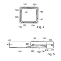
- Fig. 4 shows a schematic cross-sectional view of the beam of Fig. 3 along the indicated dotted line in Fig. 3 .
- the beam members 181 and 182, of which a section is shown in Fig. 4 are extruded aluminum profiles arranged to be telescopable. Therefore, the section of the beam member 181 is slightly smaller than the section of the beam member 182.
- the beam member 181 can be pushed or pulled or otherwise moved into the beam member 182.
- bearings 190 may be provided between the beam member 181 and the beam member 182.
- bearings are provided between two telescopable beam members.
- the bearings are usually PTFE bearings.
- roller bearings are used to ease the movement of one of the beam members in another one of the beam members.
- the beam member 181 may have a height of 416 mm and a width of 300 mm.
- the beam member 182 may have a height of 456 mm and a width of 350 mm.
- the beam member 183 may have a height of 506 mm and a width of 400 mm.
- the beam members may have a length of about 12 m, respectively.
- the minimum overlap of two beam members may be 1500 mm to ensure a reliable transmission of forces between the beam members.
- the thickness of the flanges of the hollow beam members may be reduced with the increasing width of the beam members 181, 182 and 183: 20 mm (beam member 181), 15 mm (beam member 182) and 12 mm (beam member 183).
- the web thickness may be kept constant at 8 mm to prevent buckling of the web.
- the beam members may have a mass per unit length of roughly between 80 kg/m and 100 kg/m, depending which one of the beam members 181, 182 or 183 is regarded.
- the mass per unit length of the whole beam may be about 90 kg/m for aluminium as the light weight material.
- Typical embodiments use beam members having a minimum height of at least 300 mm. Hence, the beam has a minimum height of 300 mm. In further typical embodiments beams having heights of more than 400 mm, 500 mm, 600 mm or even more than 700 mm are used. Bigger heights provide better stiffness of the beam, such that the deflection in the middle of the beam can be restricted. Also the thicknesses of the flanges and the webs of the beam members can be reduced using beam members with bigger heights. However, possible buckling puts a boundary to even smaller webs and flanges, such that no further weight reduction can be achieved. Therefore, typical embodiments use beam members having a height of less than 800 mm, 700 mm or even less than 600 mm.
- the named measures of the beam members of typical embodiments apply for all light weight materials used in embodiments of the invention, especially for aluminium and composite material beams.
- Typical embodiments provide an overlap or the telescopable beam members of at least 1200 mm, 1300 mm or even 1400 mm.
- the overlap of the beam of typical embodiments in the extended situation is less than 1800 mm or less than 2000 mm.
- the whole beam of typical embodiments has a mass per unit length of less than 150 kg/m or even less than 120 kg/m. Other embodiments have a mass per unit length of less than 100 kg/m for the whole beam.
- a "mass per unit length of the whole beam” means an average value for the whole beam, wherein some of the beam members can be lighter or heavier.
- the mass per unit length is increased compared to sections with a single beam member.
- Fig. 5 shows a detail of the embodiment of Fig. 3 schematically.
- the beam members 181 and 182 are telescopable by using a telescopic device.
- the telescopic device is a rope-type device which is usable to push the beam member 181 such that the beam members 181 and 182 are pulled apart. For this reason, a rope 200 is drawn over a rope winch 210 arranged inside of the beam member 182 and fixed to the beam member 182.
- the rope winch 210 can be used to move in the rope 200.
- the rope 200 is further drawn over a rope pulley 220, which is also fixed to the beam member 182.
- a rope pulley 230 fixed to the beam member 182 and an end fixation 240 for the rope at the beam member 181 provide a tackle-type device, such that a moving in of the rope using the rope winch 210 causes a movement of the beam member 181 in the direction of an arrow 250.
- the movement in the direction of the arrow 250 leads to an extraction of the telescopable beam members 181 and 182.
- the telescopic beam comprises a telescopic device to retract or expand the beam.
- Typical telescopic devices are hydraulic devices or rope-type devices. Other known devices are used in further typical embodiments. Also manual telescoping devices are used in typical embodiments.
- the pulling force of the tractor is used in typical embodiments to expand the telescopic beam. Therefore, the rear chassis is fixed, such that the beam can be expanded or retracted by pulling or pushing the front support frame with the tractor.
- Fig. 6 is a schematic view of a wind energy system 300, also referred to as a wind turbine.
- the wind energy system 300 includes a tower 310 to which a machine nacelle 320 is mounted at its top end.
- a hub 330 having three rotor blades 340 is mounted thereto.
- Typical embodiments of the invention allow for a transport of two of the rotor blades 340 with one truck not exceeding a maximum gross weight of 40 metric tons. Hence, traffic regulations regulating the gross weight and applying in many countries all over the world are not violated by such a truck transporting two rotor blades.
Landscapes
- Engineering & Computer Science (AREA)
- Chemical & Material Sciences (AREA)
- Combustion & Propulsion (AREA)
- Transportation (AREA)
- Mechanical Engineering (AREA)
- Architecture (AREA)
- Structural Engineering (AREA)
- Wind Motors (AREA)
- Body Structure For Vehicles (AREA)
Abstract
Description
- The present invention relates to a light weight trailer, a telescopic beam and a method of constructing a light weight trailer.
- It is known that rotor blades for wind energy systems are transferred to construction sites of the wind energy systems on a regular basis using trailers. During manufacturing of the rotor blades certain ambient conditions are necessary. Therefore, the rotor blades are usually manufactured remotely of the construction sites, where the wind energy systems are to be set up. Hence a transfer of complete rotor blades is made necessary.
- During transportation of the rotor blades trucks and trailers are used. The trailers have to be arranged to accommodate a complete rotor blade, such that the trailers have to be long enough for supporting a complete blade. This makes the trailers heavy. In view of traffic regulations, which have to be observed, the payload of such trailers is only good enough for picking up a single rotor blade of a modem wind energy system. Therefore the payload of a trailer for an elongated good such as a rotor blade has to be enhanced.
- In view of the above, a light weight trailer is provided for carrying elongated goods, especially for carrying at least one or two rotor blades of a wind energy system, including a front support frame and a rear support frame. The front support frame and the rear support frame are adapted for supporting elongated goods. Furthermore, a beam is provided which connects the front support frame with the rear support frame, wherein the beam consists substantially of a light weight material.
- According to another aspect, a telescopic beam is provided for a light weight trailer for carrying elongated goods including at least two beam members that can be telescoped into each other. At least one of the two beam members consists substantially of a light weight material.
- As used herein, telescopable beam members are understood in that the beam is extendable in order to form a beam of operational length e.g. by extracting a beam member out of the other. Further, the beam can be retracted to a shorter overall length e.g. when the beam is not used by inserting a part of the beam members into the others or by folding the beam.
- According to another aspect, a method of constructing a light weight trailer for carrying elongated goods is provided, wherein the method comprises providing a front support frame; providing a rear support frame; manufacturing a beam consisting substantially of light weight material for connecting the front support frame with the rear support frame; and mounting the beam between the front support frame and the rear support frame.
- According to a further aspect of the invention, a method of using a light weight trailer for carrying elongated goods, especially for carrying at least two rotor blades of a wind energy system, is provided. The light weight trailer typically includes a front support frame and a rear support frame. The front support frame and the rear support frame are adapted for supporting the elongated good. Furthermore, a beam is provided which connects the front support frame with the rear support frame, wherein the beam consists substantially of a light weight material.
- Further aspects, advantages and features of the present invention are apparent from the dependent claims, the description and the accompanying drawings.
- A full and enabling disclosure of the present invention, including the best mode thereof, to one of ordinary skill in the art, is set forth more particularly in the remainder of the specification, including reference to the accompanying figures wherein:
-
Fig. 1 is a schematic longitudinal-sectional view of an embodiment of of a tractor with a light weight trailer according to embodiments described herein. -
Fig. 2 is a schematic longitudinal-sectional view of an embodiment of a light weight trailer according to embodiments described herein. -
Fig. 3 is a schematic longitudinal-sectional view of an embodiment of a beam of a light weight trailer according to embodiments described herein. -
Fig. 4 shows a schematic cross-sectional view of an embodiment of a beam for a light weight trailer. -
Fig. 5 is a schematic longitudinal-sectional view of a telescoping device and a fixing device of an embodiment of a beam for a light weight trailer -
Fig. 6 is a schematic cross-sectional view of a wind energy system with rotor blades, wherein two of the rotor blades can be transported using the embodiment shown inFig. 1 . - Reference will now be made in detail to the various embodiments of the invention, one or more examples of which are illustrated in the figures. Each example is provided by way of explanation of the invention, and is not meant as a limitation of the invention. For example, features illustrated or described as part of one embodiment can be used on or in conjunction with other embodiments to yield yet a further embodiment. It is intended that the present invention includes such modifications and variations.
-
Fig. 1 is a schematic drawing of atractor 100 with alight weight trailer 110. Thelight weight trailer 110 comprises typically afront support frame 120 and arear support frame 130. On thefront support frame 120 and therear support frame 130mounts 140 can be fixed, respectively. Themounts 140 are arranged for receiving two rotor blades of a wind energy system (rf.Fig. 6 ), such that two rotor blades can be transferred using the truck and trailer combination ofFig. 1 . During transport, the two rotor blades are fixed in alignment with the longitudinal axis of thetrailer 110. - As described herein, the term "rotor blade" in the context of transporting the rotor blades is used as an example for elongated goods. Typical lengths of the elongated goods are at least 10 m, more typically at least 20 m, even more typically at least 25 m. In typical embodiments, the elongated goods are a complete rotor blade or part of a rotor blade of a wind energy system. Those rotor blades of modem wind energy systems that cannot be transported as a whole may therefore be transported split up in two or three parts.
- In typical embodiments, mounts for two rotor blades are fixed on the support frames. Other typical embodiments have mounts arranged for receiving more than two rotor blades. The maximum number of rotor blades which can be transported using embodiments described herein depends primarily on the weight and the dimension of the rotor blades since traffic regulations, especially regulations regarding the maximum gross vehicle weight have to be kept. The light weight trailer described herein may be suitable for transporting two, three or even four rotor blades.
- The light weight trailer of
Fig. 1 comprises abeam 150 connecting thefront support frame 120 with therear support frame 130. In the embodiment ofFig. 1 , thetrailer 110 is a semitrailer-type trailer, wherein therear support frame 130 serves as a chassis receiving threeaxles 160. Thefront support frame 120 includes acoupling member 170 for coupling thetrailer 110 with thetractor 100. - In typical embodiments semitrailer-type trailers are provided due to the ability of semitrailers to receive elongated goods. In other typical embodiments, two-pole-type trailers are used. Two-pole-trailers are trailers with two chassis connected by the beam. The front chassis is coupled to the tractor. In typical embodiments at least one of the axles of the trailer is a steering axle providing better maneuvering abilities for the tractor-trailer-combination.
- The
beam 150 consists substantially of light weight material. In the embodiment shown inFig. 1 , thebeam 150 consists substantially of aluminum. Thebeam 150 comprises extruded aluminum profiles manufactured using known techniques. - Typically, the use of light weight material for the beam allows for transporting of at least two rotor blades of a wind energy system reducing transportation costs. In typical embodiments alloyed aluminum is used as light weight material, such that the beam consists substantially of alloyed aluminum. Alloys may be used to improve mechanical, corrosion or welding properties. Several aluminum alloys like 6061-alloys or 7075-alloys can be used in typical embodiments described herein. Alloys for alloying aluminum for typical embodiments include copper, zinc, manganese, silicon, or magnesium. Aluminium alloys are easy to manufacture. Aluminium alloys show good corrosion and durability properties. With a beam of aluminium, a trailer weighing less than trailers in the art can be provided.
- In typical embodiments having aluminium beams, the aluminium beam or the aluminium beam members are extruded. In other typical embodiments, aluminium plates are welded to form a beam or a beam member. Aluminium alloys used in typical embodiments are widely used and inexpensive.
- In further typical embodiments, composite material is used as light weight material for the beam, such that the beam consists substantially of composite material. Several composite materials can be used, like single cure composites or dual cure composites. Examples of dual cure composites used in typical embodiments are described in the European patent application
EP 1 764 382 A1 , assigned to the same assignee, which is incorporated herein by reference. In typical embodiments, composite materials comprise glass fibers and carbon fibers embedded in a matrix. Typically, the matrix is fiber reinforced. In typical embodiments, the carbon fibers are orientated substantially parallel to the longitudinal axis of the beam. This provides a maximum stiffness with respect to bending load. Composites used in typical embodiments are also described in the European patent applicationEP 1 798 412 A2 , assigned to the same assignee, which is incorporated herein by reference. In further embodiments multilayer composite materials are used. Such multilayer materials are described in the United States PatentUS 7,153,576 B2 , assigned to the same assignee, which is incorporated by reference. Reference is made to the chemicals and the methods of manufacture described in the above-named European patent applications and the United States Patent. Typically, the beam comprising composite material is manufactured by laminating layers of fiber material. Typically glass fibers and carbon fibers are used, wherein the matrix comprises typically resin, such as epoxy resin. Composites are very light, such that the beam of composite material is very light and the trailer comprising such a beam has a maximum payload. Furthermore, composite materials provide high stiffness. Hence, deflection of the beam comprising composite material as the primary or the supporting material is kept low. - The term "consists substantially of light weight material" as used herein embraces all constructions consisting substantially of aluminum, composite material or another light weight material, respectively. Typically, the beam comprises fixations for fixing the beam at the support frames. Theses fixations are part of the beam but can be of a different material as compared to the main part of the beam, such that most of the beam is made of light weight material except some special parts. Typically, the term "consists substantially of light weight material" as used herein means that the mass percentage of light weight material of the beam compared to the overall weight of the beam amounts to at least 75%, more typically 80%, even more typically 90% or even 95%. This applies similarly for the terms "consists substantially of aluminum" and "consists substantially of composite material". Typical light weight materials used in embodiments described herein are aluminum and composite materials like glass-carbon-composites, glass-steel-composites and glass composites. In further typical embodiments combinations of composite materials with aluminum materials are used.
- In the embodiment shown in
Fig. 1 , thebeam 150 is extendable. Thebeam 150 is a telescopic beam, which comprises threetelescopic beam members telescopic beam members beam member 183, which is the biggest one of thebeam members rear support frame 130 thereby entering the rear support frame partly or completely. Hence, therear support frame 130 can act as a fourth hollow beam member of the telescopic beam. Due to thetelescopic beam 150, thetrailer 110 can be converted in a retracted position (not shown), such that the gross length of the trailer can be reduced remarkably. - Typically, the beam is extendable. In typical embodiments described herein, the beam is a telescopic beam comprising at least two telescopable beam members. Also three, four or even more telescopable beam members are comprised in typical embodiments described herein. Typically, the beam comprises a fixing device for fixing the beam in a retracted position or an extended position. In further embodiments, the extendable beam is foldable, such that it can be transformed into a folded position. In use, the foldable beam is extended and used to connect the rear support frame and the front support frame.
-
Fig. 2 is a schematic drawing of a light weight trailer according to embodiments described herein. With respect toFig. 2 , same reference numbers are used for same or equal parts compared toFig. 1 and the description ofFig. 1 . However, thebeam 150 of the embodiment shown inFig. 2 consists substantially of composite material. The composite material is a glass fiber and carbon fiber material, wherein the fibers are embedded in a matrix material. -
Fig. 3 is a schematic drawing of a beam of a light weight trailer according to embodiments described herein. With respect toFig. 3 , same reference numbers are used for same or equal parts compared toFig. 1 and the description ofFig. 1 . The beam as described herein may be used for equipping a trailer with. Accordingly, trailers known in the art having beams of a high weight may be re-equipped with the beam as described herein. -
Fig. 4 shows a schematic cross-sectional view of the beam ofFig. 3 along the indicated dotted line inFig. 3 . Again, same reference numbers are used for same or equal parts as in conjunction withFigs. 1 and3 . Thebeam members Fig. 4 , are extruded aluminum profiles arranged to be telescopable. Therefore, the section of thebeam member 181 is slightly smaller than the section of thebeam member 182. Thebeam member 181 can be pushed or pulled or otherwise moved into thebeam member 182. For a low-friction movement of thebeam member 181 in thebeam member 182,bearings 190 may be provided between thebeam member 181 and thebeam member 182. - Typically, bearings are provided between two telescopable beam members. The bearings are usually PTFE bearings. In other typical embodiments, roller bearings are used to ease the movement of one of the beam members in another one of the beam members.
- With reference to
Figs. 1 to 4 , as explicit example, thebeam member 181 may have a height of 416 mm and a width of 300 mm. Thebeam member 182 may have a height of 456 mm and a width of 350 mm. Finally, thebeam member 183 may have a height of 506 mm and a width of 400 mm. The beam members may have a length of about 12 m, respectively. The minimum overlap of two beam members may be 1500 mm to ensure a reliable transmission of forces between the beam members. The thickness of the flanges of the hollow beam members may be reduced with the increasing width of thebeam members beam members - Typical embodiments use beam members having a minimum height of at least 300 mm. Hence, the beam has a minimum height of 300 mm. In further typical embodiments beams having heights of more than 400 mm, 500 mm, 600 mm or even more than 700 mm are used. Bigger heights provide better stiffness of the beam, such that the deflection in the middle of the beam can be restricted. Also the thicknesses of the flanges and the webs of the beam members can be reduced using beam members with bigger heights. However, possible buckling puts a boundary to even smaller webs and flanges, such that no further weight reduction can be achieved. Therefore, typical embodiments use beam members having a height of less than 800 mm, 700 mm or even less than 600 mm. The named measures of the beam members of typical embodiments apply for all light weight materials used in embodiments of the invention, especially for aluminium and composite material beams. Typical embodiments provide an overlap or the telescopable beam members of at least 1200 mm, 1300 mm or even 1400 mm. The overlap of the beam of typical embodiments in the extended situation is less than 1800 mm or less than 2000 mm. The whole beam of typical embodiments has a mass per unit length of less than 150 kg/m or even less than 120 kg/m. Other embodiments have a mass per unit length of less than 100 kg/m for the whole beam. A "mass per unit length of the whole beam" means an average value for the whole beam, wherein some of the beam members can be lighter or heavier. Of course, in overlapping sections of the telescopable beam members, the mass per unit length is increased compared to sections with a single beam member.
-
Fig. 5 shows a detail of the embodiment ofFig. 3 schematically. Thebeam members beam member 181 such that thebeam members rope 200 is drawn over arope winch 210 arranged inside of thebeam member 182 and fixed to thebeam member 182. Therope winch 210 can be used to move in therope 200. Therope 200 is further drawn over arope pulley 220, which is also fixed to thebeam member 182. - Furthermore, a
rope pulley 230 fixed to thebeam member 182 and anend fixation 240 for the rope at thebeam member 181 provide a tackle-type device, such that a moving in of the rope using therope winch 210 causes a movement of thebeam member 181 in the direction of anarrow 250. The movement in the direction of thearrow 250 leads to an extraction of thetelescopable beam members - In typical embodiments, the telescopic beam comprises a telescopic device to retract or expand the beam. Typical telescopic devices are hydraulic devices or rope-type devices. Other known devices are used in further typical embodiments. Also manual telescoping devices are used in typical embodiments. The pulling force of the tractor is used in typical embodiments to expand the telescopic beam. Therefore, the rear chassis is fixed, such that the beam can be expanded or retracted by pulling or pushing the front support frame with the tractor.
-
Fig. 6 is a schematic view of awind energy system 300, also referred to as a wind turbine. Thewind energy system 300 includes atower 310 to which amachine nacelle 320 is mounted at its top end. Ahub 330 having threerotor blades 340 is mounted thereto. Typical embodiments of the invention allow for a transport of two of therotor blades 340 with one truck not exceeding a maximum gross weight of 40 metric tons. Hence, traffic regulations regulating the gross weight and applying in many countries all over the world are not violated by such a truck transporting two rotor blades. - This written description uses examples to disclose the invention, including the best mode, and also to enable any person skilled in the art to make and use the invention. While the invention has been described in terms of various specific embodiments, those skilled in the art will recognize that the invention can be practiced with modification within the spirit and scope of the claims. Especially, mutually non-exclusive features of the embodiments described above may be combined with each other. The patentable scope of the invention is defined by the claims, and may include other examples that occur to those skilled in the art. Such other examples are intended to be within the scope of the claims if they have structural elements that do not differ from the literal language of the claims, or if they include equivalent structural elements with insubstantial differences from the literal languages of the claims.
- Aspects and of the present invention are defined in the following numbered clauses:
- 1. A light weight trailer for carrying elongated goods having
- a front support frame;
- a rear support frame, with said front support frame and said rear support frame being adapted for supporting an elongated good; and
- a beam connecting said front support frame with said rear support frame, wherein
- 2. The light weight trailer according to clause 1 wherein said light weight trailer is a semitrailer-type trailer.
- 3. The light weight trailer according to clause 1 or clause 2 wherein said light weight material comprises aluminum.
- 4. The light weight trailer according to any one of the preceding clauses, wherein said light weight material comprises a composite material.
- 5. The light weight trailer according to clause 4 wherein said composite material comprises glass fibers in a matrix material.
- 6. The light weight trailer according to clause 4 or clause 5 wherein said composite material comprises carbon fibers embedded in a matrix material.
- 7. The light weight trailer according to any one of the preceding clauses, wherein said beam is extendable.
- 8. The light weight trailer according to any one of the preceding clauses, wherein said beam is a telescopic beam.
- 9. The light weight trailer according to clause 8 wherein said telescopic beam comprises at least two telescopable beam members.
- 10. The light weight trailer according to clause 8 or clause 9 wherein said telescopic beam comprises a telescoping device.
- 11. The light weight trailer according to any one of the preceding clauses, with said beam having a minimum height of at least 300mm.
- 12. The light weight trailer according to any one of the preceding clauses, with said beam having a minimum width of at least 200mm.
- 13. The light weight trailer according to any one of the preceding clauses, with said beam having a mass per unit length of less than 120 kg/m.
- 14. A telescopic beam for a light weight trailer for carrying an elongated good having at least two telescopable beam members, wherein at least one of said at least two beam members consists substantially of a light weight material.
- 15. The telescopic beam according to clause 14 wherein said light weight material comprises aluminum.
- 16. The telescopic beam according to clause 14 wherein said light weight material comprises a composite material.
- 17. A method of constructing a light weight trailer for carrying elongated goods, said method comprising
- providing a front support frame;
- providing a rear support frame;
- manufacturing a beam consisting substantially of light weight material for connecting said front support frame with said rear support frame; and
- mounting said beam between said front support frame and said rear support frame.
- 18. The method according to clause 17, wherein said beam is manufactured by preparing at least two telescopable beam members and telescoping said beam members.
- 19. The method according to clause 18, wherein said preparing of said beam members comprises extruding a hollow aluminum beam body.
- 20. The method according to clause 18, wherein said preparing of said beam members comprises preparing of a hollow beam member consisting of composite material.
Claims (15)
- A light weight trailer (110) for carrying elongated goods having
a front support frame (120);
a rear support frame (130), with said front support frame (120) and said rear support frame (130) being adapted for supporting an elongated good; and
a beam (150) connecting said front support frame (120) with said rear support frame (130), wherein
said beam (150) consists substantially of a light weight material. - The light weight trailer (110) according to claim 1 wherein said light weight material comprises aluminum or a composite material.
- The light weight trailer (110) according to claim 2 wherein said composite material comprises glass fibers in a matrix material.
- The light weight trailer (110) according to claim 2 or claim 3, wherein said composite material comprises carbon fibers embedded in a matrix material.
- The light weight trailer (110) according to any one of the preceding claims wherein said beam (150) is extendable.
- The light weight trailer (110) according to any one of the preceding claims claim 1 wherein said beam (150) is a telescopic beam.
- The light weight trailer (11) according to claim 6 wherein said telescopic beam comprises at least two telescopable beam members.
- The light weight trailer according to claim 6 or claim 7, wherein said telescopic beam comprises a telescoping device.
- The light weight trailer (110) according to any one of the preceding claims, with said beam (150) having a mass per unit length of less than 120 kg/m.
- A telescopic beam (150) for a light weight trailer for carrying an elongated good having at least two telescopable beam members (181, 182, 183), wherein at least one of said at least two beam members (181, 182, 183) consists substantially of a light weight material.
- The telescopic beam (150) according to claim 10 wherein said light weight material comprises aluminum or a composite material.
- A method of constructing a light weight trailer (110) for carrying elongated goods, said method comprising
providing a front support frame (120);
providing a rear support frame (130);
manufacturing a beam (150) consisting substantially of light weight material for connecting said front support frame (120) with said rear support frame (130); and
mounting said beam (150) between said front support frame (120) and said rear support frame (130). - The method according to claim 12, wherein said beam is manufactured by preparing at least two telescopable beam members and telescoping said beam members.
- The method according to claim 13, wherein said preparing of said beam members comprises extruding a hollow aluminum beam body.
- The method according to claim 13, wherein said preparing of said beam members comprises preparing of a hollow beam member consisting of composite material.
Applications Claiming Priority (1)
| Application Number | Priority Date | Filing Date | Title |
|---|---|---|---|
| US12/261,210 US20100109309A1 (en) | 2008-10-30 | 2008-10-30 | Light weight beam and trailer |
Publications (2)
| Publication Number | Publication Date |
|---|---|
| EP2181910A2 true EP2181910A2 (en) | 2010-05-05 |
| EP2181910A3 EP2181910A3 (en) | 2010-11-17 |
Family
ID=40904728
Family Applications (1)
| Application Number | Title | Priority Date | Filing Date |
|---|---|---|---|
| EP09164086A Withdrawn EP2181910A3 (en) | 2008-10-30 | 2009-06-30 | Light weight beam and trailer |
Country Status (3)
| Country | Link |
|---|---|
| US (1) | US20100109309A1 (en) |
| EP (1) | EP2181910A3 (en) |
| CN (1) | CN101722884A (en) |
Cited By (3)
| Publication number | Priority date | Publication date | Assignee | Title |
|---|---|---|---|---|
| CN105923553A (en) * | 2016-06-12 | 2016-09-07 | 国网山东省电力公司枣庄供电公司 | Special tool for conveying electric pole |
| CN106542008A (en) * | 2016-12-08 | 2017-03-29 | 安溪县中磊设备制造有限公司 | A kind of intelligence Handling device for loading oil exploration equipment |
| CN113459935A (en) * | 2021-07-14 | 2021-10-01 | 菏泽京九特种汽车有限公司 | All-terrain wind power generation blade transport vehicle |
Families Citing this family (24)
| Publication number | Priority date | Publication date | Assignee | Title |
|---|---|---|---|---|
| CN102963612B (en) * | 2011-09-01 | 2014-12-31 | 上海利星行物流有限公司 | Transportation equipment for transporting wind power equipment bades |
| CN102815254B (en) * | 2012-08-29 | 2015-06-17 | 江苏法尔胜新型管业有限公司 | Method for transporting large-caliber ultralong sea-crossing steel wire mesh plastic composite pipes |
| DE102013210142A1 (en) * | 2013-05-31 | 2014-12-04 | Saf-Holland Gmbh | handlebar unit |
| US9302708B2 (en) * | 2013-09-20 | 2016-04-05 | Bull Moose Heavy Haul, Inc. | Support member for a trailer |
| DE202013104703U1 (en) * | 2013-10-18 | 2014-04-16 | J.G.B.D. Consult Sprl | Heavy duty vehicle module |
| US10596950B2 (en) | 2015-02-23 | 2020-03-24 | Wabash National, L.P. | Composite refrigerated truck body and method of making the same |
| MX2018002939A (en) | 2015-09-08 | 2018-06-18 | Wabash National Lp | Joining a suspension assembly to a composite trailer structure. |
| US10549789B2 (en) | 2015-09-08 | 2020-02-04 | Wabash National, L.P. | Joining a rail member to a composite trailer structure |
| MX2016013715A (en) | 2015-10-23 | 2017-12-20 | Wabash National Lp | Extruded molds and methods for manufacturing composite truck panels. |
| US10329763B2 (en) | 2016-02-24 | 2019-06-25 | Wabash National, L.P. | Composite floor structure and method of making the same |
| US10479419B2 (en) | 2016-02-24 | 2019-11-19 | Wabash National, L.P. | Composite refrigerated semi-trailer and method of making the same |
| US10239566B2 (en) | 2016-02-24 | 2019-03-26 | Wabash National, L.P. | Composite floor for a dry truck body |
| US10479405B2 (en) | 2016-08-31 | 2019-11-19 | Wabash National, L.P. | Mounting bracket for a composite truck body floor |
| US10543875B2 (en) | 2016-12-20 | 2020-01-28 | Équipement Max-Atlas International Inc. | Extendable trailer for freight containers |
| US10407103B2 (en) | 2017-01-11 | 2019-09-10 | Wabash National, L.P. | Mounting bracket for a truck body and method for mounting a composite truck body to a chassis |
| CA3206527A1 (en) | 2017-08-10 | 2019-02-10 | Wabash National, L.P. | Transverse beam for composite floor structure and method of making the same |
| AU2018220122B2 (en) | 2017-08-25 | 2022-12-01 | Wabash National, L.P. | Composite floor structure with embedded hardpoint connector and method of making the same |
| CN108248312A (en) * | 2017-12-11 | 2018-07-06 | 天津智源机械制造股份有限公司 | A kind of flat bogie |
| US12337903B2 (en) | 2021-03-12 | 2025-06-24 | Wabash National, L.P. | Reinforced preforms for optimized composite structures |
| CN113650679A (en) * | 2021-08-22 | 2021-11-16 | 中国重汽集团泰安五岳专用汽车有限公司 | Transport semitrailer apparatus and method for overlength components |
| US12539802B2 (en) | 2021-12-07 | 2026-02-03 | Wabash National, L.P. | Embedded mounting inserts |
| CN114735082B (en) * | 2022-04-01 | 2024-04-09 | 岚图汽车科技有限公司 | Telescopic beam, telescopic chassis and vehicle |
| CN115123323A (en) * | 2022-07-25 | 2022-09-30 | 中车戚墅堰机车有限公司 | Body for remote-controlled locomotives |
| US20260014903A1 (en) * | 2024-07-09 | 2026-01-15 | Ford Global Technologies, Llc | Support assembly for a vehicle |
Citations (5)
| Publication number | Priority date | Publication date | Assignee | Title |
|---|---|---|---|---|
| US3087744A (en) * | 1960-10-26 | 1963-04-30 | Tanenbaum Joseph | Long load vehicle |
| US4226436A (en) * | 1978-07-24 | 1980-10-07 | Donaldson Jack D | Application for locking device for telescoping reaches of logging trailers |
| US7153576B2 (en) | 2004-01-20 | 2006-12-26 | General Electric Company | Weatherable multilayer article assemblies and method for their preparation |
| EP1764382A1 (en) | 2005-09-20 | 2007-03-21 | General Electric Company | Dual cure compositions, methods of curing thereof and articles therefrom |
| EP1798412A2 (en) | 2005-12-15 | 2007-06-20 | General Electric Company | Connection of wind turbine blade to rotor hub |
Family Cites Families (25)
| Publication number | Priority date | Publication date | Assignee | Title |
|---|---|---|---|---|
| US2796266A (en) * | 1956-06-15 | 1957-06-18 | James R Sells | Wagon chassis |
| US2982580A (en) * | 1958-10-27 | 1961-05-02 | Stanley N Lewis | Trailer chassis and sub-floor structure |
| US3508763A (en) * | 1968-05-22 | 1970-04-28 | Gen Motors Corp | Dirigible wheel suspension with unitary lower control arms and torsional roll stabilizer |
| US3612569A (en) * | 1969-01-29 | 1971-10-12 | Joseph A Marinelli | Trailer construction |
| US3718346A (en) * | 1970-08-27 | 1973-02-27 | Freightliner Corp | Truck comprising tractor and semi-trailer |
| US4111450A (en) * | 1977-04-18 | 1978-09-05 | Pinto Robert R | Multiple hook-up, movable axle trailer with removable track extensions, slidable kingpin, and pivotal axle assemblies |
| US4365820A (en) * | 1978-09-12 | 1982-12-28 | Rush Donald L | Trailer connecting running gear |
| US4817537A (en) * | 1987-03-16 | 1989-04-04 | Cripe Alan R | Container carrying convertible rail-highway vehicle |
| US5335932A (en) * | 1992-06-26 | 1994-08-09 | Nai Neway, Inc. | Apparatus for mounting a trailing arm air suspension to a sliding frame |
| US5322314A (en) * | 1992-08-07 | 1994-06-21 | Rosby Corporation | Thin gooseneck assembly |
| US5421612A (en) * | 1992-09-10 | 1995-06-06 | Floe; Wayne | Trailer and tongue structure |
| US5454597A (en) * | 1993-04-29 | 1995-10-03 | Great Dane Trailers, Inc. | Lightweight chassis-container construction |
| NL9400578A (en) * | 1994-04-12 | 1995-11-01 | Koninkl Nooteboom Trailers Bv | Extendable vehicle |
| US5655792A (en) * | 1994-12-29 | 1997-08-12 | East Manufacturing | Composite trailer and van type container assembly using bi-metal materials |
| US5685554A (en) * | 1995-10-27 | 1997-11-11 | Poxleitner; Harold C. | Telescoping tow bar apparatus |
| GB2340796B (en) * | 1998-08-22 | 2002-04-03 | Kevin William Raven | Extendible flatbed trailers |
| BE1013229A3 (en) * | 2000-01-13 | 2001-11-06 | Groep Stevens Int Nv | SUPPORT FOR A VEHICLE AND METHOD FOR MANUFACTURING OF SPARS therefor. |
| BE1013655A3 (en) * | 2000-08-24 | 2002-05-07 | Groep Stevens Int Nv | Support for a vehicle. |
| US7004308B2 (en) * | 2003-09-24 | 2006-02-28 | Roach Manufacturing Corporation | Steerable telescoping conveyor for loading parcels |
| US7198298B2 (en) * | 2003-10-15 | 2007-04-03 | Hendrickson Usa, L L C | Movable subframe for semi-trailers |
| US7204665B2 (en) * | 2004-04-02 | 2007-04-17 | The Cretex Companies, Inc. | Support structure apparatus and method |
| EP1609704B1 (en) * | 2004-06-22 | 2007-08-08 | MTB Baustoffhandelsgesellschaft mbH & Co. KG | Chassis for heavy goods vehicle or trailer |
| WO2007120273A2 (en) * | 2005-11-18 | 2007-10-25 | Hendrickson International Corporation | Frame for heavy-duty vehicles |
| WO2007106913A2 (en) * | 2006-03-16 | 2007-09-20 | Hendrickson International Corporation | Frame for heavy-duty vehicles |
| US7607873B2 (en) * | 2006-03-21 | 2009-10-27 | 21St Century Structures, Llc | Concrete panel trailer assembly with strut-mounted wheels |
-
2008
- 2008-10-30 US US12/261,210 patent/US20100109309A1/en not_active Abandoned
-
2009
- 2009-06-30 EP EP09164086A patent/EP2181910A3/en not_active Withdrawn
- 2009-07-15 CN CN200910159383A patent/CN101722884A/en active Pending
Patent Citations (5)
| Publication number | Priority date | Publication date | Assignee | Title |
|---|---|---|---|---|
| US3087744A (en) * | 1960-10-26 | 1963-04-30 | Tanenbaum Joseph | Long load vehicle |
| US4226436A (en) * | 1978-07-24 | 1980-10-07 | Donaldson Jack D | Application for locking device for telescoping reaches of logging trailers |
| US7153576B2 (en) | 2004-01-20 | 2006-12-26 | General Electric Company | Weatherable multilayer article assemblies and method for their preparation |
| EP1764382A1 (en) | 2005-09-20 | 2007-03-21 | General Electric Company | Dual cure compositions, methods of curing thereof and articles therefrom |
| EP1798412A2 (en) | 2005-12-15 | 2007-06-20 | General Electric Company | Connection of wind turbine blade to rotor hub |
Cited By (3)
| Publication number | Priority date | Publication date | Assignee | Title |
|---|---|---|---|---|
| CN105923553A (en) * | 2016-06-12 | 2016-09-07 | 国网山东省电力公司枣庄供电公司 | Special tool for conveying electric pole |
| CN106542008A (en) * | 2016-12-08 | 2017-03-29 | 安溪县中磊设备制造有限公司 | A kind of intelligence Handling device for loading oil exploration equipment |
| CN113459935A (en) * | 2021-07-14 | 2021-10-01 | 菏泽京九特种汽车有限公司 | All-terrain wind power generation blade transport vehicle |
Also Published As
| Publication number | Publication date |
|---|---|
| CN101722884A (en) | 2010-06-09 |
| EP2181910A3 (en) | 2010-11-17 |
| US20100109309A1 (en) | 2010-05-06 |
Similar Documents
| Publication | Publication Date | Title |
|---|---|---|
| EP2181910A2 (en) | Light weight beam and trailer | |
| US10766607B2 (en) | Landing gear | |
| AU2009283881B2 (en) | Vehicle rollover protection roof geometry and structure | |
| US8541091B2 (en) | Composite leg for landing gear assembly | |
| US12084820B2 (en) | Mobile barrier with a sliding reinforced wall | |
| CN104136319A (en) | Landing gear | |
| US20120085723A1 (en) | Boom element, telescopic boom and construction vehicle | |
| WO2014000831A1 (en) | Carrier element and energy absorption element of hybrid construction for a motor vehicle | |
| US7648324B1 (en) | Loading platform system with slide unit | |
| US20060055207A1 (en) | Floor structure of a motor vehicle | |
| EP2723656A1 (en) | Freight holding device, in particular for loading aircraft, method for producing a freight holding device and use of a pultruded fibre-reinforced profile element for a freight holding device | |
| DE102009021961A1 (en) | Body structure for motor vehicle, has body support shortened due to impact load after lifting supportive connection between elongate sections by compression of deformation element that is held between elongate sections of body support | |
| DE102009008674B4 (en) | Body structure of a vehicle | |
| NO334391B1 (en) | Railway vehicles with a deformable driver's cab with a suitable repeater interface | |
| CN106394684A (en) | High-strength automobile frame | |
| CN214780293U (en) | Be applied to two-way flexible body frame mechanism of guardrail installation car | |
| KR102000651B1 (en) | Assembly type Arm roll truck having detachable sub-frame | |
| US20070182149A1 (en) | Cross shaft for semitrailer landing gear | |
| CN220948183U (en) | Telescoping mechanism for module transport vehicle | |
| EP3408212B1 (en) | Supporting structure for a crane, and crane therewith | |
| CN219790297U (en) | But pull formula sub vehicle frame transport platform | |
| CN115556831B (en) | Lower collision channel assembly structure and vehicle | |
| DE102012111128B4 (en) | missile | |
| CN202529035U (en) | Dumper frame rear end reinforcing improved structure | |
| CN218112774U (en) | Vehicle chassis and drainage vehicle |
Legal Events
| Date | Code | Title | Description |
|---|---|---|---|
| PUAI | Public reference made under article 153(3) epc to a published international application that has entered the european phase |
Free format text: ORIGINAL CODE: 0009012 |
|
| AK | Designated contracting states |
Kind code of ref document: A2 Designated state(s): AT BE BG CH CY CZ DE DK EE ES FI FR GB GR HR HU IE IS IT LI LT LU LV MC MK MT NL NO PL PT RO SE SI SK TR |
|
| AX | Request for extension of the european patent |
Extension state: AL BA RS |
|
| PUAL | Search report despatched |
Free format text: ORIGINAL CODE: 0009013 |
|
| AK | Designated contracting states |
Kind code of ref document: A3 Designated state(s): AT BE BG CH CY CZ DE DK EE ES FI FR GB GR HR HU IE IS IT LI LT LU LV MC MK MT NL NO PL PT RO SE SI SK TR |
|
| AX | Request for extension of the european patent |
Extension state: AL BA RS |
|
| 17P | Request for examination filed |
Effective date: 20110517 |
|
| 17Q | First examination report despatched |
Effective date: 20110801 |
|
| STAA | Information on the status of an ep patent application or granted ep patent |
Free format text: STATUS: THE APPLICATION IS DEEMED TO BE WITHDRAWN |
|
| 18D | Application deemed to be withdrawn |
Effective date: 20120214 |